![BOOK OF ABSTRACTS · 2007. 3. 16. · [C088] Gamma Titanium Aluminide Matrix Composites: A Parametric Study of Optimum Constituents 83 J.S. Craft and W. S. Johnson [C001] The Effect](https://static.fdocuments.net/doc/165x107/606b3af84a82022923479c71/book-of-2007-3-16-c088-gamma-titanium-aluminide-matrix-composites-a-parametric.jpg)
Microstructures for Two-Phase Gamma Titanium Aluminide ... · Microstructures for Two-Phase Gamma...
14
TECHNICAL ARTICLE Microstructures for Two-Phase Gamma Titanium Aluminide Fabricated by Electron Beam Melting Jennifer Hernandez • Lawrence E. Murr • Sara M. Gaytan • Edwin Martinez • Frank Medina • Ryan B. Wicker Received: 2 November 2011 / Accepted: 16 December 2011 / Published online: 28 February 2012 Ó Springer Science+Business Media, LLC and ASM International 2012 Abstract Pre-alloyed (Ti-48Al-2Cr-2Nb) powder was used to fabricate solid, fully dense (3.85 g/cm 3 ) compo- nents by electron beam melting (EBM). Foam components with densities from 0.33 to 0.46 g/cm 3 were also fabricated by EBM. Both the solid and the foam component micro- structures were characterized by an equiaxed, duplex grain structure (15 lm diameter) containing lamellar a 2 (Ti 3 Al)/c (TiAl) plates *20 nm. Light optical metallography and transmission electron microscopy illustrated that these microstructures confirmed the (111) c /(001) a2 duplex orientation relationship. Solid components annealed at 1150 °C at 5 h and 1380 °C at 1 h exhibited a fine-grain (3 lm diameter) duplex structure and a large, equiaxed, fully lamellar grain structure (550 lm diameter), respec- tively. The lamellar structure consisted mostly of coherent {111} c (TiAl) twins with a width of *0.9 lm. These diverse annealed microstructures exhibited residual hard- ness values similar to the as-fabricated EBM components. Keywords Two-phase TiAl Electron beam melting Metallography and microstructure analysis Hardness measurements Introduction For more than two decades, c-titanium aluminides (c-TiAl) have been considered to be novel and practical candidates for automotive engine components, industrial and aviation turbines (especially compressor blades), as well as struc- tural applications in oxidizing environments up to *700 °C. Above 900 °C both TiO 2 and Al 2 O 3 surface corrosion products occur. This is due primarily to attractive properties which include low density (q * 3.9 g/cm 3 ), high specific strength (r c /q), high specific stiffness (E/q), and good corrosion/oxidation resistance as noted; where r c and E are the yield strength and Young’s mod- ulus, respectively. As noted in a comprehensive review by Appel and Wagner [1], single-phase c-TiAl, like many intermetallic phases at room temperature, exhibits poor ductility and fracture toughness while two-phase alloys with composi- tions in the (c ? a) two-phase region of the Ti-Al (binary) phase diagram (Fig. 1) can exhibit improved ductility and toughness. Extensive research has been carried out to develop two-phase c-TiAl-based alloys consisting of c-TiAl with the ordered face-centred tetragonal L1 O structure (p4mmm; a % 0.41 nm % b and essentially, fcc), and a 2 -Ti 3 Al with the hexagonal DO 19 structure (p63/ mmc; a = 0.58 nm, c = 0.46 nm) [1, 2]. Additions of b-stabilizing elements such as Cr, Nb, W, and Mo can also produce the body-centered cubic b-phase (Fig. 1) which is softer than the c and a 2 phases at elevated temperature [3]. This may influence creep properties and can create b pre- cipitates at lamellar a 2 /c interfaces. The c-TiAl compositions have been difficult to process using pre-alloyed powders in conventional PM processing [4] while investment castings or processing ingots to var- ious mill product forms has also posed problems such as J. Hernandez (&) L. E. Murr S. M. Gaytan E. Martinez Department of Metallurgical and Materials Engineering, University of Texas at El Paso, El Paso, TX 79968, USA e-mail: [email protected] J. Hernandez L. E. Murr S. M. Gaytan E. Martinez F. Medina R. B. Wicker W. M. Keck Center for 3D Innovation, University of Texas at El Paso, El Paso, TX 79968, USA 123 Metallogr. Microstruct. Anal. (2012) 1:14–27 DOI 10.1007/s13632-011-0001-9
Transcript of Microstructures for Two-Phase Gamma Titanium Aluminide ... · Microstructures for Two-Phase Gamma...

TECHNICAL ARTICLE
Microstructures for Two-Phase Gamma Titanium AluminideFabricated by Electron Beam Melting
Jennifer Hernandez • Lawrence E. Murr •
Sara M. Gaytan • Edwin Martinez •
Frank Medina • Ryan B. Wicker
Received: 2 November 2011 / Accepted: 16 December 2011 / Published online: 28 February 2012
� Springer Science+Business Media, LLC and ASM International 2012
Abstract Pre-alloyed (Ti-48Al-2Cr-2Nb) powder was
used to fabricate solid, fully dense (3.85 g/cm3) compo-
nents by electron beam melting (EBM). Foam components
with densities from 0.33 to 0.46 g/cm3 were also fabricated
by EBM. Both the solid and the foam component micro-
structures were characterized by an equiaxed, duplex grain
structure (15 lm diameter) containing lamellar a2 (Ti3Al)/c(TiAl) plates *20 nm. Light optical metallography and
transmission electron microscopy illustrated that these
microstructures confirmed the (111)c/(001)a2 duplex
orientation relationship. Solid components annealed at
1150 �C at 5 h and 1380 �C at 1 h exhibited a fine-grain
(3 lm diameter) duplex structure and a large, equiaxed,
fully lamellar grain structure (550 lm diameter), respec-
tively. The lamellar structure consisted mostly of coherent
{111} c (TiAl) twins with a width of *0.9 lm. These
diverse annealed microstructures exhibited residual hard-
ness values similar to the as-fabricated EBM components.
Keywords Two-phase TiAl � Electron beam melting �Metallography and microstructure analysis � Hardness
measurements
Introduction
For more than two decades, c-titanium aluminides (c-TiAl)
have been considered to be novel and practical candidates
for automotive engine components, industrial and aviation
turbines (especially compressor blades), as well as struc-
tural applications in oxidizing environments up to
*700 �C. Above 900 �C both TiO2 and Al2O3 surface
corrosion products occur. This is due primarily to attractive
properties which include low density (q * 3.9 g/cm3),
high specific strength (rc/q), high specific stiffness
(E/q), and good corrosion/oxidation resistance as noted;
where rc and E are the yield strength and Young’s mod-
ulus, respectively.
As noted in a comprehensive review by Appel and
Wagner [1], single-phase c-TiAl, like many intermetallic
phases at room temperature, exhibits poor ductility and
fracture toughness while two-phase alloys with composi-
tions in the (c ? a) two-phase region of the Ti-Al (binary)
phase diagram (Fig. 1) can exhibit improved ductility and
toughness. Extensive research has been carried out to
develop two-phase c-TiAl-based alloys consisting of
c-TiAl with the ordered face-centred tetragonal L1O
structure (p4mmm; a % 0.41 nm % b and essentially,
fcc), and a2-Ti3Al with the hexagonal DO19 structure (p63/
mmc; a = 0.58 nm, c = 0.46 nm) [1, 2]. Additions of
b-stabilizing elements such as Cr, Nb, W, and Mo can also
produce the body-centered cubic b-phase (Fig. 1) which is
softer than the c and a2 phases at elevated temperature [3].
This may influence creep properties and can create b pre-
cipitates at lamellar a2/c interfaces.
The c-TiAl compositions have been difficult to process
using pre-alloyed powders in conventional PM processing
[4] while investment castings or processing ingots to var-
ious mill product forms has also posed problems such as
J. Hernandez (&) � L. E. Murr � S. M. Gaytan � E. Martinez
Department of Metallurgical and Materials Engineering,
University of Texas at El Paso, El Paso, TX 79968, USA
e-mail: [email protected]
J. Hernandez � L. E. Murr � S. M. Gaytan � E. Martinez �F. Medina � R. B. Wicker
W. M. Keck Center for 3D Innovation, University of Texas
at El Paso, El Paso, TX 79968, USA
123
Metallogr. Microstruct. Anal. (2012) 1:14–27
DOI 10.1007/s13632-011-0001-9

thermal stress-induced cracking, especially at lower tem-
peratures [5]. More recently, Cormier et al. [6] and Murr
et al. [7] have demonstrated the fabrication of c-TiAl
prototypes by additive manufacturing using electron beam
melting (EBM). In all the processing routes for c-TiAl, the
as-processed microstructure usually assumes some duplex
form (c ? a 2): c-TiAl lamellae with interspersed a2-Ti3Al;
often equiaxed lamellar colonies interspersed with c-TiAl
grains containing no lamellae [1, 2]. The lamellar structure
is formed when Ti-rich two-phase alloys are hot worked or
heat treated in the vicinity of the a transus line (Fig. 1), and
displays a plate-like morphology consisting of parallel,
thick plates of c-TiAl, and very fine plates of a2-Ti3Al. The
orientation relationship between the two phases is well
documented to be [1, 8]:
111ð Þcjj 000ð Þa2 and h1�10�cjjh11�20ia2;
where the (111) plane is parallel to the lamellae (a2/c)
interfaces.
Unlike nickel-titanium alloys or nickel aluminides,
titanium aluminides have not been fabricated in porous or
open-cellular structure forms [9, 10]. These forms are ideal
in applications where properties must be optimized in
relation to the overall system weight and high-temperature
applications with severe environments. Novel and complex
mesh and foam structures have recently been fabricated for
Ti-6Al-4V [11] and Co-base and Ni-base superalloys [12]
having relative densities (q/qo) as low as 0.075.
In this study, we examined the microstructures in fully
dense c-TiAl components fabricated by additive manufac-
turing (AM) using EBM of pre-alloyed, atomized powder
using light optical metallography (LOM) and transmission
electron microscopy (TEM). Preliminary open-cellular
(foam) components were also fabricated for a range of
densities (q), and the foam-ligament microstructures also
observed by LOM.
Experimental Procedures
Fabrication of Solid Components by EBM
Figure 2 shows a schematic view for the Arcam A2 EBM
system and examples of solid component geometries fab-
ricated in this study. The EBM system is composed pri-
marily of an electron optical column (1 in Fig. 2) which
generates electrons in a gun with an acceleration potential
of 60 kV. Electromagnetic lenses focus the electron beam
and scan coils scan the beam selectively across powder
layers formed by raking the powder, gravity fed from
cassettes shown at (2) in Fig. 2. Selective melting directed
Fig. 1 Central portion of the binary Ti-Al phase diagram. The
compositional ranges are shown hatched for two-phase engineering
materials. Te = 1124 �C is the eutectoid temperature. Between Te and
Ta (the a transus temperature) duplex microstructures with ranging
volume fraction of lamellar grains occurs. Dotted line shows alloy
composition for this study
Fig. 2 EBM system schematic and solid component geometries
Metallogr. Microstruct. Anal. (2012) 1:14–27 15
123

by a CAD model creates a build layer at (3) in Fig. 2
forming components shown layer-by-layer. Prior to the
melt scan the beam is rapidly scanned at higher beam
current to pre-heat the raked powder layer in multiple
passes, and the final melt scan is accomplished at reduced
scan speed and beam current [11]. Figure 3(a) illustrates
the rapidly solidified (atomized) pre-alloyed powder hav-
ing a composition of Ti-48Al-2Cr-2Nb (in atomic percent),
while Fig. 3(b) shows the corresponding powder size dis-
tribution and average powder particle size.
Foam Component Building Strategy
Stochastic foams of c-TiAl were fabricated from CAD
models developed from CT scans of conventional alumi-
num foams as discussed in detail elsewhere [11]. This
digital layer data was imported into bitmap files repre-
senting image or model slices with specific pixel dimen-
sions to create expandable elements for the development of
models implicit in Fig. 4. These file-model representations
can be altered dimensionally to create cell size or pore size
variations as well as ligament dimension variations (par-
ticularly thickness), resulting in specific density or porosity
variations [11].
Microstructural and Material Characterization
Microstructures for solid and open-cellular EBM fabricated
components were observed by LOM using a digital imag-
ing metallograph. Precursor, pre-alloyed powder micro-
structures were also examined by embedding in a mounting
epoxy and grinding, polishing, and etching to reveal par-
ticle interiors. Etching of exposed powder interiors as well
as mounted, ground, and polished solid and foam samples
utilized a solution consisting of 5 mL HNO3, 10 mL HF,
and 300 mL H2O. Samples were etched generally for *1 s
and washed in ethanol to remove residual etchant. Samples
were also observed in a Hitachi S-8500 field emission
scanning electron microscope (SEM) operated at 20 kV,
utilizing an EDAX energy dispersive (x-ray) spectrometer
(EDS) attachment for elemental analysis. Powder and solid
(including foam) specimens were also examined by x-ray
diffraction (XRD) using a Bruker AXS-D8 (Discover)
XRD system.
Sections were cut from the EBM-fabricated solid com-
ponents illustrated in Fig. 2 in slices oriented either parallel
or perpendicular to the build direction indicated by the
Fig. 4 Stochastic foam model for EBM building of open-cellular
c-TiAl components created from CT-scan data. (a) 3D foam model.
(b) Face view for foam pore and ligament structure
Fig. 3 Pre-alloyed Ti-Al precursor powder (a) and powder particle
size distribution histogram (b). The average powder particle size
(including attached satellite particles) is shown to be 52 lm
16 Metallogr. Microstruct. Anal. (2012) 1:14–27
123

arrow at the lower left in Fig. 2. These slices were ground
and polished to a thickness of 200 lm and 3 mm discs
punched from them. These discs were electropolished from
both sides in a dual jet electropolishing unit operated at a
polishing current ranging from *5 to 10 A at *15 V. The
electropolishing solution consisted of 950 mL methanol
and 50 mL perchloric acid at -30 �C. The electropolished/
electrothinned discs were examined in a Hitachi H-9500
high-resolution TEM operating at 300 kV, fitted with a
digital CCD camera and an EDAX elemental analysis
(EDS) system.
Residual microindentation (Vickers) hardness for the
mounted, polished, and etched powder as well as the solid
components (Fig. 2), and foam sample ligaments, was
measured using a Struers-Doramin A-300, digital instru-
mental system; utilizing a 100 gf (1 N) load with a dwell
time of 10 s. For solid sections, a minimum of 10 inden-
tations were made following standard steel block calibra-
tion. Similar indentations were made for mounted foam
ligaments which were at least three indenters wide.
This assured microindentation measurements were
representative.
Fig. 5 Magnified views for the precursor Ti-48Al-2Cr-2Nb powder
in Fig. 3(a)Fig. 6 Magnified views for the powder particle in Fig. 5 showing
microdendritic grain structure
Fig. 7 LOM section views showing internal, equiaxed, dendritic
grain structure of the pre-alloyed precursor powder
Metallogr. Microstruct. Anal. (2012) 1:14–27 17
123

Results and Discussion
Figures 5 to 7 illustrate the powder microstructure to be an
equiaxed, microdendritic (cellular) grain structure
(*2 lm) exhibiting a duplex a2/c crystal structure (a2/c = 0.5)
as illustrated in the XRD spectra of Fig. 8. In comparison,
Figs. 9 and 10 show 3D composite LOM views of the solid,
rectangular, and cylindrical EBM component (Fig. 2)
microstructures to consist of a duplex (a2/c), equiaxed
grain structure (*15 lm grain size) composed of colony-
lamellar substructures, primarily c-TiAl. The measured
density for the solid components averaged 3.85 g/cm3.
XRD spectra corresponding to the horizontal and vertical
reference plane section for Figs. 9 and 10 are shown
in Figs. 11 and 12, respectively, where a2/c % 0.05.
Figure 13 shows an LOM (lower magnification) view of
the vertical plane section corresponding to Fig. 10 (cylin-
drical component) illustrating etching contrast delineating
successive layering, representative of layer thicknesses of
*100 lm.
Figure 14 shows foam prototype components repre-
senting a range of densities, indicated. The SEM view in
Fig. 15, typical for the ligaments, shows the partially
melted/sintered powder particles characterizing the surface
structure. Figure 16 shows a typical LOM view of the
ligament microstructure which corresponds to those shown
in Figs. 9 and 10 for the solid components: exhibiting a
generally equiaxed duplex grain structure *15 lm grainFig. 8 XRD spectra for the Ti-48Al-2Cr-2Nb precursor powder in
Fig. 3(a)
Fig. 9 3D-LOM composite view for dual-phase c-TiAl microstruc-
ture representative of the EBM-fabricated rectangular solid (Fig. 2).
The build direction is indicated by the arrow (left)
Fig. 10 3D-LOM composite view for dual-phase c-TiAl microstruc-
ture representative of the EBM-fabricated cylindrical solid (Fig. 2).
The build direction is indicated by the arrow (left)
18 Metallogr. Microstruct. Anal. (2012) 1:14–27
123

diameter. The XRD spectra characteristic of the foam lig-
aments are shown in Fig. 17. In contrast to the corre-
sponding solid component XRD spectra shown in Figs. 11
and 12, the foam exhibits slightly less a2 (a2/c B 0.05).
Figure 18 compares typical horizontal and vertical ref-
erence plane TEM images characterizing microstructures
illustrated in the LOM-3D composition in Fig. 9. These
images show relatively equiaxed c-TiAl grains with and
without a2/c lamellar microstructures. Figures 19 to 21
show the details of the lamellar a2/c microstructures in the
horizontal reference plane of a rectangular (block) com-
ponent (Fig. 2) specimen. Figure 19 shows a large,
lamellar-containing grain separated from smaller, generally
equiaxed c-TiAl grains. Figure 20 shows the details of the
thin a2 (hcp) coincident plates 11�1ð Þcjj 0001ð Þa2) which are
perpendicular to the (123) fcc (c-TiAl) surface orientation
as indicated in the selected-area electron diffraction
(SAED) pattern insert showing c-TiAl and a2-Ti3Al
diffraction spots along ½11�1�c (arrow in Fig. 20 SAED
pattern inset); perpendicular to the ð11�1Þ plane which is
perpendicular to the (123) surface plane or indicated pre-
viously. These a2 platelets are roughly only 20 nm thick,
while in some cases both the a2 and c regions have similar
thicknesses as illustrated in the bright-field/dark-field (DF)
TEM sequence shown in Fig. 21(a) and (b), respectively,
where only small c-TiAl platelets reverse contrast in DF
(Fig. 21b).
While the solid, cylindrical EBM components (Fig. 2)
exhibited microstructures essentially the same as those
shown for comparison in Figs. 9 and 10, and the TEM
images illustrated in Figs. 18 to 21, the TEM images
shown in Figs. 22 to 25 illustrate similar and related
microstructures which characterize the solid components
overall. Figure 22 shows a horizontal section view for a
cylindrical sample containing some a2 platelets within the
c-TiAl as well as a relatively high density of dislocation
structures. Correspondingly, Fig. 23 illustrates a large
array of dislocation dipoles in a similar specimen section.
There are strain contrast regions along a2/c interfaces to the
left in Fig. 23 (arrow). These may be ledge structures
Fig. 11 XRD spectra corresponding to the horizontal and vertical
reference planes for a rectangular EBM-fabricated block (represented
by Fig. 9)
Fig. 12 XRD spectra corresponding to the horizontal and vertical
reference planes for a cylindrical EBM-fabricated component (rep-
resented by Fig. 10)
Metallogr. Microstruct. Anal. (2012) 1:14–27 19
123

illustrated in previous work of Appel et al. [2]. Figure 24
shows a c-TiAl grain containing thin a2 platelets having the
same orientation/crystallographic relationships noted for
Fig. 20. The arrow in Fig. 24 is identical to the arrow in the
SAED pattern inset in Fig. 20, and represents the ½11�1�direction characterizing the arrays of diffraction spots in
the SAED pattern inset in Fig. 24. Figure 25, in contrast to
Fig. 21, illustrates a bright-field/DF sequence showing
contrast reversal for large segments of a2 platelets, utilizing
the operating reflection shown circled in the SAED pattern
inset in Fig. 25.
In the conventional processing of titanium aluminides,
including ingot metallurgy [13], investment casting [14],
and powder metallurgy [15], duplex microstructures fol-
lowing HIP (after investment casting) at temperatures
around 1200 �C appear similar to those shown in Figs. 9
and 10 and Fig. 16 for solid and foam components,
respectively. Near-c (globular) microstructures consisting
of very fine, equiaxed grains (*10 lm) have been
observed after two-step isothermal forging at 1220 �C,
while fully lamellar microstructure occurs with additional
heat treatment at 1370 �C/1 h ? 900 �C/6 h ? 20 �C
which produces an equiaxed grain structure with average
grain sizes[300 lm [2]. The duplex microstructure yields
the highest elongation (*2%) with poor toughness
[1, 16], while the fully lamellar grain structures exhibit
Fig. 13 Low-magnification LOM image showing additive-larger
structures in the vertical reference plane for a cylindrical EBM-
fabricated component (represented by Fig. 10)
Fig. 14 Ti-48Al-2Cr-2Nb foam prototypes fabricated by EBM. Top row shows edge orientations while bottom row shows face orientations at
slight larger magnifications. Measure densities are indicated
20 Metallogr. Microstruct. Anal. (2012) 1:14–27
123

improved creep strength and fracture toughness, with
reduced elongation in contrast to the fine-grain, duplex
structures [1, 17].
In this research program, we emulated these contem-
porary microstructures by annealing the EBM-fabricated,
rectangular block specimens shown in Fig. 2 using two
schedules: (1) specimens were annealed at 1150 �C for 5 h
in purified argon (and furnace cooled); (2) specimens were
annealed at 1380 �C for 1 h in argon (and furnace cooled).
For schedule (1), a single-step annealing process, equiaxed
fine grains (*3 lm) occurred with some remanent larger-
grain, occluded clusters. For schedule (2) or anneal (2), a
large equiaxed, fully lamellar grain structure was observed
having an average grain size of 550 lm. Figure 26 com-
pares these two anneal schedule microstructures observed
by LOM. Figure 27 shows some examples of the Anneal
(1) microstructures/substructures observed in the TEM,
where in contrast to the TEM images shown in Figs. 18 and
19 for the EBM-fabricated, solid block specimens, there is
no corresponding lamellar microstructure, and irregular a2
platelets are intermixed with c-TiAl {111} twins. This is
particularly notable in Fig. 27(b) which shows a slightly
magnified (123)-oriented grain with ð�1�11Þ and ð1�11Þcoincident lamellae. Correspondingly, Fig. 28 shows a
bright-field/DF TEM sequence showing thin, c-TiAl 11�1
twins intermixed with thin lamellar a2 (Ti3Al). The SAED
pattern inset shows the ½11�1� direction (arrow) normal to
the ð11�1Þ planes which are correspondingly normal to the
Fig. 15 SEM views for ligament structure of foam sample
(q = 0.33 g/cm3) showing partially sintered powder particles.
(a) Low-magnification SEM image. (b) High-magnification view
showing partially sintered powder particles
Fig. 16 Foam ligament microstructure: OM image showing duplex
(two-phase) structure
Fig. 17 XRD spectra for the foam components
Metallogr. Microstruct. Anal. (2012) 1:14–27 21
123

(123) grain surface. These orientation and crystallographic
features emulate those shown previously in Figs. 20 and
21. In contrast to the EBM-fabricated block and cylindrical
solids, the annealed microstructures shown in Figs. 26 to
28 exhibit somewhat limited a2 (Ti3Al) coincident phase.
This is particularly evident on comparing the SAED pat-
terns in Figs. 20 and 21 with Fig. 28. The reduced a2-phase
is also evident from the corresponding XRD spectra as
represented for the vertical reference planes for the two
anneal schedules as shown in Fig. 29. The a2 (002) and
(201) peaks prominent in the 1150 �C anneal (top in
Fig. 29) are absent in the 1380 �C anneal (bottom in
Fig. 29). The a2 (200) peak is small but unchanged for the
two anneals. This is somewhat consistent with the TEM
results shown in Figs. 27 and 28, respectively. Taken
together, Figs. 26(b), 28, and the bottom XRD spectra in
Fig. 29 are indicative of a lack of a2 (Ti3Al) phase. TEM
bright- and DF analyses for the 1380 �C anneal samples
indicated a significant fraction of the lamellar ‘‘plates’’ to
be c-twins. This is illustrated typically in the bright-field/
DF TEM images represented in Fig. 30, where the grain
surface orientation is (122), and the operating reflection for
the twins coincided with the ð02�2Þ diffraction spot. The
average ‘‘lamellar’’ plate spacing was measured to be
*0.9 lm from TEM images. This is also the twin width as
illustrated in the DF image inset in Fig. 30. Twin planes
along ½41�3� in Fig. 30 are coincident with ð1�11Þ planes,
inclined *79� to the (122) grain surface plane.
Fig. 18 Comparative TEM images for two-phase microstructures in
EBM-fabricated c-TiAl cylindrical component. (a) Horizontal refer-
ence plane. (b) Vertical reference plane (Fig. 10)
Fig. 19 TEM bright-field image showing lamellar (a2/c) filled grain
(top) and primarily c-TiAl grains (bottom)
Fig. 20 Magnified TEM bright-field image showing thin a2-Ti3Al
plates in c-TiAl. The SAED pattern inset shows rows of c and a2
diffraction spots. These rows are in the ½11�1�c direction (arrow). The
grain surface orientation is (123)
22 Metallogr. Microstruct. Anal. (2012) 1:14–27
123
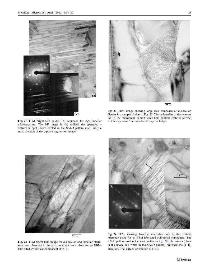
Fig. 21 TEM bright-field (a)/DF (b) sequence for a2/c lamellar
microstructure. The DF image in (b) utilized the apertured cdiffraction spot shown circled in the SAED pattern inset. Only a
small fraction of the c-phase regions are imaged
Fig. 22 TEM bright-field image for dislocation and lamellar micro-
structures observed in the horizontal reference plane for an EBM-
fabricated cylindrical component (Fig. 2)
Fig. 23 TEM image showing large area composed of dislocation
dipoles in a sample similar to Fig. 22. The a2 lamellae at the extreme
left of the micrograph exhibit strain-field contrast features (arrow)
which may arise from interfacial steps or ledges
Fig. 24 TEM showing lamellar microstructures in the vertical
reference plane for an EBM-fabricated cylindrical component. The
SAED pattern inset is the same as that in Fig. 20. The arrows (black
in the image and white in the SAED pattern) represent the ½11�1�cdirection. The surface orientation is (123)
Metallogr. Microstruct. Anal. (2012) 1:14–27 23
123

Discussion
Figure 26, in retrospect, represents a primarily c-twinned
(coherent {111} boundaries) microstructure with twins
(and some coincident a2-Ti3Al phase platelets) forming a
singular crystallographic ({111}) lamellar microstructure
in the large, equiaxed grains. While the mechanism of twin
formation is not fully understood, c-twin boundary energies
are certainly a fraction of the grain boundary energies, and
their formation during anneal (at 1380 �C), from a simple
thermodynamic point of view, is consistent with a reduc-
tion in the total free energy; especially the interfacial free
energy contribution [18]. This energy reduction is further
optimized by the growth of twin lamellae and the elimi-
nation of the coincident a2 (Ti3Al) phase.
The lamellar c-TiAl twin structures which dominate the
1380 �C anneal (Fig. 26b) are reminiscent of nanoscale
growth twin lamellae observed by Lu et al. [19] in nano-
grained copper synthesized using a pulsed electrodeposit-
ion technique which allowed for the nano-twin spacings to
be varied from *100 to * 15 nm, and dramatically
enhancing mechanical properties (as much as a ten-fold
increase in tensile strength in contrast to commercial, bulk
copper) [20]. It is intriguing to speculate about the pros-
pects for producing much smaller lamellar twin spacings in
EBM-fabricated and selectively annealed c-TiAl to
enhance mechanical properties in a similar fashion, but not
necessarily at the low-nanoscale.
Some indication of prospects for manipulating the
mechanical properties for EBM-fabricated c-TiAl products
is provided in Fig. 31 which compares the Vickers micr-
oindentation hardness (HV) and the Rockwell C-scale
(macroindentation) hardness (HRC) for the variety of
EBM-fabricated products in this research program. Con-
sidering first the HV values [averaged in the horizontal and
vertical reference planes for the solid block and cylindrical
components and the block anneal schedules (Anneal 1 and
2)], there is a significant increment between the precursor
(pre-alloyed) c-TiAl powder and the foam ligaments. This
is an indication of the a2 (Ti3Al) hardness representing a
micro-dendritic structure in contrast to an equiaxed, a2/cgrain structure in the foam ligaments. Correspondingly, the
Fig. 25 Bright-field (a)/DF (b) TEM image sequence of a2/c lamellar
microstructure in an EBM-fabricated cylindrical component (in the
vertical reference plane). The DF image in (b) corresponds to the
circled a2 diffraction spot in the SAED pattern inset. The DF images
in (b) represent portions of a2 plates
Fig. 26 LOM views for annealed EBM-built blocks in the vertical
reference plane (parallel to the build direction. (a) Anneal (1):
1150 �C at 5 h. (b) Anneal (2): 1380 �C at 1 h
24 Metallogr. Microstruct. Anal. (2012) 1:14–27
123

HV averages for all the solid components (including the
annealed block) vary only by a few percent. This is par-
ticularly notable on comparing the EBM-fabricate block
[with an equiaxed grain size of *15 lm (containing)
lamellar a2/c spaced *100 nm with the 1380 �C anneal
(Anneal 2)] where the equiaxed grain size was 550 lm
with a ‘‘lamellar’’ spacing of *0.9 lm. Correspondingly,
the HV average increased slightly from 4.3 to 4.5 GPa. In
contrast, the HRC averages (Fig. 31) declined for the
EBM-fabricated block when annealed at 1380 �C: from
HRC 42 to HRC 35, a 17% decrease. This is probably due
primarily to the increased grain size for the 1380 �C anneal
(Anneal 2). Certainly, optimizing the anneal schedule to
reduce the grain size while simultaneously reducing the
lamellar twin (or a2-phase) thickness (and spacing) could
raise the strength significantly. This prospect for interfacial
microstructural engineering could lead to significant
advances for c-TiAl applications for components fabricated
by EBM, especially prospects for annealed foam compo-
nents as illustrated in Fig. 14.
In this context, it is interesting to note that the specific
yield strength for c-TiAl has been shown to be a maximum
of *150 MPa/g/cm3 [1]. However, assuming as a simple
rule-of-thumb that the yield strength is equal to one-third of
the Vickers microindentation hardness [18], the solid
EBM-fabricated components exhibit a specific strength of
312 MPa/g/cm3 while the lowest density foam (Fig. 14)
would have a corresponding specific strength of 3333 MPa/
g/cm3 (with reference to Fig. 31). This foam strength
corresponds to an ideal specific yield strength nearly 200
times the conventional c-TiAl specific strength [1].
Summary and Conclusions
EBM fabrication of rectangular, solid blocks, and cylinders
(with nominal density of 3.85 g/cm3) from pre-alloyed (Ti-
48Al-2Cr-2Nb) powders has been examined by LOM and
TEM. The microstructures exhibit a generally equiaxed, c-
Fig. 27 Bright-field TEM images representing Anneal (1) (1150 �C
at 5 h); corresponding to the LOM image in Fig. 26(a). (a) Mixture of
fine a2 and c-twins. (b) Similar features for a larger grain with a (123)
surface orientation. Corresponding c-{111} trace directions are noted
Fig. 28 TEM bright-field (a)/DF (b) image sequence utilizing the
combined a2/c diffraction spots shown circled in the SAED pattern
inset in (b). The TEM image sequence corresponds to Anneal (2)
(1380 �C at 1 h) in the vertical reference plane, characteristic of the
LOM image in Fig. 26(b). The arrow in the SAED pattern inset
corresponds to ½11�1� for a (123) grain surface orientation
Metallogr. Microstruct. Anal. (2012) 1:14–27 25
123

TiAl grain structure with a2/c colonies exhibiting lamellar
a2/c platelets. Grain sizes averaged *15 lm. This is in
contrast to interdendritic spacings for mostly a2 (Ti3Al) in
the precursor powder of *2 lm. XRD spectra for the solid
components allowed a2/c to be estimated as 0.05 in contrast
to *0.5 for the precursor powder. Prototype foam com-
ponents, ranging in density from 0.33 to 0.46 g/cm3
exhibited a ligament grain structure/duplex microstructure
essentially the same as the solid components; including a2/
c % 0.05.
TEM bright- and DF sequences for the solid block and
cylinder EBM fabricated components confirmed the a2/clamellar, duplex microstructures to be the same as those
characterized earlier for more conventionally processed c-
TiAl: investment casting and powder metallurgy-produced
ingots. This included the (111)c||(0001)a2 orientation
relationship.
Simple anneal schedules for the solid block EBM fab-
ricated components included 1150 �C at 5 h and 1380 �C
at 1 h. These produced a fine, equiaxed duplex grain
Fig. 29 XRD spectra corresponding to the vertical reference planes
represented in Fig. 26(a) and (b), respectively
Fig. 30 TEM bright-field image for c-twins coincident with (111) in
a c-TiAl (122) grain surface orientation. A DF image portion is
inserted and corresponds to the twinned regions referenced by the
arrow(s)
Fig. 31 Comparison of Vickers microindentation hardness averages
(HV) and Rockwell C-scale hardness averages (HRC) for experi-
mental specimens noted. The block, cylinder, Anneal (1), and Anneal
(2) specimens averaged measurements made in the horizontal and
vertical reference planes
26 Metallogr. Microstruct. Anal. (2012) 1:14–27
123

structure (*3 lm) with a2/c\ 0.05, and a very large,
equiaxed grain structure (*550 lm) with a fully lamellar
microstructure, respectively. TEM bright- and DF image
sequencing along with XRD spectral data indicated that a2/
c � 0.05, and the lamellar structure to be mostly coherent
{111} c-TiAl twins. This lamellar twin structure averaged
twin widths and spacings of *0.9 lm in contrast to
lamellar a2 (Ti3Al) widths of *20 nm and spacings of
*0.1 lm in the as-fabricated components.
Both annealed components (1150 and 1380 �C) exhib-
ited Vickers microindentation hardnesses similar to the
EBM-fabricated components, suggesting that optimizing
the grain size and reducing the lamellar coherent twin
spacings through selective annealing could allow for
superior mechanical properties for a range of applications
of EBM-fabricated c-TiAl products.
Acknowledgments We are grateful to Dave Abbott of GE for the
provision of the pre-alloyed TiAl powder. This research was sup-
ported in part by a Mr. and Mrs. MacIntosh Murchison Endowment at
the University of Texas at El Paso.
References
1. F. Appel, R. Wagner, Microstructure and deformation of two-
phase c-titanium aluminides. Mater. Sci. Eng. R22, 187–268
(1998)
2. F. Appel, U. Brossmann, U. Christoph, S. Eggert, P. Janschek, U.
Lorenz, J. Mullar, M. Oehring, J.D.H. Paul, Recent progress in
the development of gamma titanium aluminide alloys. Adv. Eng.
Mater. 2(11), 699–720 (2000)
3. H. Zhu, D.Y. Seo, K. Maruyama, Strengthening behavior of beta
phase in lamellar microstructure of TiAl alloys. J. Manag. 62(1),
64–69 (2010)
4. T.E. O’Connell, J.A. Miller, Interior Technical Report AFML-TR-78-129 (WPAFB, Dayton, 1978)
5. F.H. Froes, C. Suryanarayana, D. Eliezer, Synthesis, properties
and applications of titanium alumines (review). J. Mater. Sci. 27,
5113–5140 (1992)
6. D. Cormier, O.L. Harryson, T. Mahale, H. West, Free form
fabrication of titanium aluminide via electron beam melting using
prealloyed and blended powders. Res. Lett. Mater. Sci. 2007,
article Ib34737 (2007)
7. L.E. Murr, S.M. Gaytan, A. Ceylan, E. Martinez, J.L. Martinez,
D.H. Hernandez, B.I. Machado, D.A. Ramirez, F. Medina, S.
Collins, R.B. Wicker, Characterization of titanium aluminide
alloy components fabricated by additive manufacturing using
electron beam melting. Acta Mater. 58, 1887–1894 (2010)
8. H. Inui, M.H. Oh, A. Nakamura, M. Yamagushi, Ordered
domains in TiAl coexisting with Ti3Al in the lamellar structure of
Ti-rich TiAl compounds. Philos. Mag. A66, 539–555 (1992)
9. M. Barnabes, P. Sevilla, J.A. Planell, F.J Gill, Mechanical
properties of nickel-titanium foams for reconstructive orthope-
dics. Mater. Sci. Eng. 28(1), 23-27 (2008)
10. A.M. Hodge, D.C. Dunand, Modeling of creep in open-cell NiAl
foams. Metall. Mater. Trans. A 34, 2352–2361 (2003)
11. L.E. Murr, S.M. Gaytan, F. Medina, H. Lopez, E. Martinez, D.H.
Hernandez, M.I. Lopez, R.B. Wicker, J. Bracke, Next generation
biomedical implants using additive manufacturing of complex
cellular and functional mesh arrays. Philos. Trans. R. Soc. A 368,
1999–2032 (2010)
12. L.E. Murr, S.J. Li, Y.-X. Tian, K. Amato, E. Martinez, F. Medina,
Open-cellular Co-base and Ni-base superalloys fabricated by
electron beam melting. Materials 4, 782–790 (2011)
13. C. Koeppe, A. Bartels, J. Seeger, H. Mecking, General aspects of
the thermomechanical treatment of two-phase intermetallic TiAl
compounds. Metall. Trans. 24A, 1795–1802 (1993)
14. Y.-W. Kim, R. Wagner, M. Yamaguchi (eds.), Gamma TitaniumAluminides (TMS, Warrendale, 1995)
15. R. Wagner, F. Appel, B. Dugan, R.J. Eniss, U. Lorenz, J. Mull-
auer, H.P. Nicolai, W. Quadakkers, L. Singheiser, W. Smarsly,
W. Vaidya, K. Wurzwallner, in Gamma Titanium Aluminides, ed.
by Y.-W. Kim, R. Wagner, M. Yamaguchi (TMS, Warrendale,
1975), p. 387
16. B. London, Structural Intermetallics (TMS, Warrendale, 1993),
p. 151
17. Y.-W. Kim, Ordered intermetallic alloys: part III: gamma tita-
nium aluminides. J. Manag. 46, 30–35 (1994)
18. L.E. Murr, Interfacial Phenomena in Metals and Alloys (Addi-
son-Wesley, Reading, 1975) (reprinted in 1990 and available
from CRBL.com)
19. L. Lu, Y.-F. Shen, Xr.H. Chen, L. Qian, K. Lu, Ultrahigh strength
and high electrical conductivity in copper. Science 304, 422–426
(2005)
20. K. Lu, L. Lu, S. Suresh, Strengthening materials, by engineering
coherent internal boundaries at the nanoscale. Science 324, 349–
352 (2009)
Metallogr. Microstruct. Anal. (2012) 1:14–27 27
123