Unique Dry Film Photoresist System for TSV Via Formation ...

IOP PUBLISHING JOURNAL OF MICROMECHANICS AND MICROENGINEERING
J. Micromech. Microeng. 22 (2012) 085010 (12pp) doi:10.1088/0960-1317/22/8/085010
Microstructure formation via roll-to-rollUV embossing using a flexible mouldmade from a laminated polymer–copperfilmZ W Zhong1,3 and X C Shan2
1 School of Mechanical and Aerospace Engineering, Nanyang Technological University,50 Nanyang Avenue, Singapore 639798, Singapore2 Singapore Institute of Manufacturing Technology, 71 Nanyang Drive, Singapore 638075,Singapore
E-mail: [email protected]
Received 7 February 2012, in final form 30 May 2012Published 4 July 2012Online at stacks.iop.org/JMM/22/085010
AbstractRoll-to-roll large format UV embossing processes aim to revolutionize the manufacturing offunctional films, with the ability to process a large area at one time, resulting in highthroughput and cost reduction. In this paper, we present the experimental results obtainedduring the process development for roll-to-roll large format UV embossing. Flexible mouldswere fabricated from a hybrid film substrate made of a liquid crystal polymer with clad copperfoils laminated on both sides of it. The effective pattern area of the fabricated flexible mouldwas 400 mm × 300 mm with a minimal feature size of 50 μm. The results show that theroll-to-roll embossing processes are capable of producing micro-scale structures andfunctional devices over a large area at one time. Large-area roll-to-roll embossing wasdemonstrated by using the hybrid flexible mould, and micro-features and structures such asmicro-channels and dot arrays were replicated on thermoplastic substrates. In addition to itsease and low cost in fabrication, the hybrid flexible moulds demonstrated to have acceptablefidelity and durability. The hybrid flexible mould is a novel solution for large-area embossing.
(Some figures may appear in colour only in the online journal)
1. Introduction
To manufacture microscale and nanoscale features, continuousdevelopment of photolithography could result in significantcost increases, while scanning beam lithography requiresmany hours to pattern a small area [1]. Using conventionalfabrication techniques would eventually result in massivecost increases and low throughput levels [2]. Therefore, newtechniques based on moulding and embossing have emergedas promising alternatives, and nanoimprint lithography is sucha technique [3–9].
3 Author to whom any correspondence should be addressed.
Micro-embossing is a promising method for formingmicro-patterns on thermoplastic substrates [10–12]. Toimprove the fidelity of embossed features, increasing theprocess temperature or pressure is one solution. However, thismay result in cracks or even breakage of the mould if the mouldis made of a brittle material. The embossed thin polymer layermay suffer from the breakage or warpage when it is peeledoff from a rigid mould during mould release. A flexible andthin mould can prevent the embossed thin polymer layer frombeing deformed or warped during mould release.
However, utilizing flat moulds is inappropriate for large-area patterning because the cost of the moulds is veryhigh and there are uniformity and releasing problems inlarge-scale flat moulding processes [13]. In contrast, roll-to-
0960-1317/12/085010+12$33.00 1 © 2012 IOP Publishing Ltd Printed in the UK & the USA

J. Micromech. Microeng. 22 (2012) 085010 Z W Zhong and X C Shan
Figure 1. The process flow chart for roll-to-roll UV embossing.
roll embossing applies the continuous roll-to-roll process todrastically increase the patterning speed. There is on-goingresearch to develop roll-to-roll embossing and increase itsrange of applications [6, 7, 14–20]. Roll-to-roll embossingis productive and cost-effective for high-volume fabricationonce moulds are fabricated [15, 17]. Roll-to-roll embossingand roller embossing have been used in fabricating componentsfor microfluidic devices [11, 12, 15, 21], textile fibres [22] andmicro-optical devices [23].
There are three approaches for mould configuration: (1)patterns are formed directly on an embossing roller surfacevia precision machining, plating or chemical etching [24, 25],which is a high-cost approach; (2) patterns are fabricated ona thin film by plating or etching, which is overlapped atop aplastic substrate and fed by embossing rollers [26], and (3)patterns are fabricated on a flexible and thin film to forma mould, which is wrapped around an embossing roller [6].Flexible moulds are frequently used in approaches (2) and (3),and were fabricated via photolithography and Ni plating onthin Ni foils, and are essential for large-area roller embossing[27] and roll-to-roll embossing [6, 17]. One challenge forlarge-area embossing is how to fabricate a mould with highfidelity at a low cost.
Recently, flexible moulds have gained popularityfor large-area imprinting [28–31]. Flexible moulds madeup of polycarbonate, polydimethylsiloxane (PDMS) andpolyethylene terephthalate films can be fabricated usingNi masters with micro-patterns and thermal nanoimprintequipment [32]. They have found many new applications for
life science, biomedicine, solar cells and optoelectronics. Fornew applications such as e-paper, flexible solar cells, flexibledisplays and polymeric microfluidic devices, the productsizes become larger and larger. Continuous roller-pressingprocesses have been currently applied in industrial fieldssuch as flexography printing and gravure printing [33]. Aflexible PDMS magnetic mould and an electromagnetic disk-controlled magnetic force can replicate the microstructuresonto large-area, curved surface glass, which finds applicationsin micro-sensory and optical facilities [34]. An approach forsoft nanoimprint lithography on nonstandard sample sizes hasbeen proposed, which uses PDMS as a flexible mould material[35]. UV nanoimprint using flexible moulds also enables thefabrication of bio-devices, micro-optics, MEMS and a widerange of nanoelectronic components [36].
A flexible mould fabrication process called pressure-assisted moulding has been reported for high-resolution softUV nanoimprint lithography [37]. PDMS is used as the flexiblemould to duplicate the pattern of a hard mould, and animprinting material is sprayed onto the PDMS mould to buildSU-8 microstructures on LED surfaces by UV-assisted rollerimprinting [38]. Nanoscale patterning of magnetic islandsby imprint lithography using a flexible mould has also beendemonstrated for the increasing magnetic recording densitytowards 100 Gbit cm−2 [39].
This work focused on the investigations of themicrostructure formation via a roll-to-roll UV embossingprocess using a flexible mould as a master template. Differentfrom those discussed above, the flexible moulds used in thiswork were fabricated from a hybrid film substrate made ofa liquid crystal polymer with clad copper foils laminated onboth sides of it. Micro-patterns on the moulds were formed byetching the copper foils. Characterizations of micro-featureson the flexible moulds were performed. Various experimentswere carried out to investigate the embossing process using aprototyped roll-to-roll UV embossing machine.
2. Experiments
The process flow of roll-to-roll UV embossing is shown infigure 1. After the establishment of a roll-to-roll UV embossingmachine, proper flexible films and liquid resins were selected.A flexible mould was attached on the embossing roller, and
Figure 2. Schematic diagram of the UV embossing system.
2
J. Micromech. Microeng. 22 (2012) 085010 Z W Zhong and X C Shan
Figure 3. The resin viscosity and the shear stress versus shear rate.
Figure 4. The resin viscosity versus the temperature.
roll-to-roll coating of liquid UV curable resin was performed.The pressure between the film and mould, which resulted fromthe web tension, enabled mould-filling of the resin. Embossingwas conducted by UV exposure. The embossed film was thenseparated from the embossing roller by means of the webtension applied by a rewinding motor. The profiles of theembossed structures were evaluated via off-line measurementsby using an optical microscope and a stylus profilometer.
We target to develop roll-to-roll large-area ultraviolet(UV) embossing processes for fabricating micro-features onflexible plastic films. The prototyped roll-to-roll embossingmachine used in this work is shown in figure 2. A coating andembossing module is located at the centre of the machine andcontains all the components required for the photosensitiveresin coating on the flexible film substrate, the embossing andthe curing through UV light exposure. The key componentsin this model include a slot die coater, an embossing rollerand a UV lamp. By using different flexible moulds, variousstructures can be fabricated by roll-to-roll UV embossing.A web handling module is located at the two ends of themachine, drives the flexible film substrate, controls its web-
(a)
(b)
100 mm
50 mm
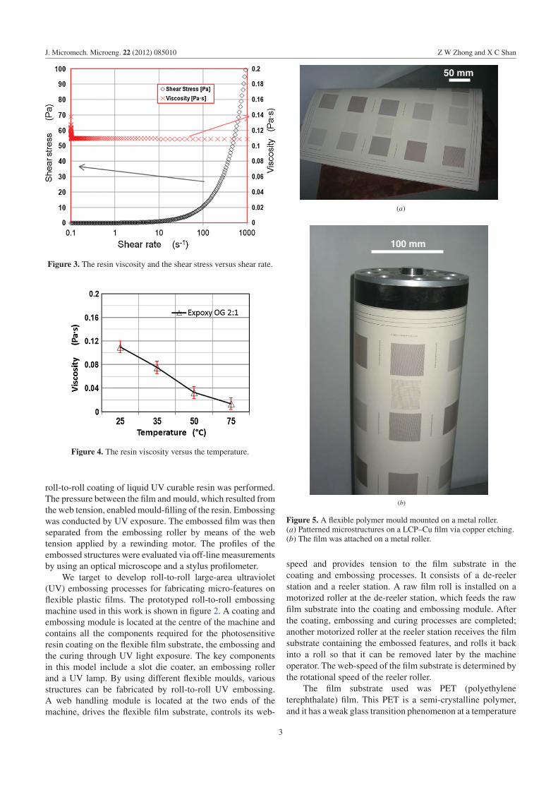
Figure 5. A flexible polymer mould mounted on a metal roller.(a) Patterned microstructures on a LCP–Cu film via copper etching.(b) The film was attached on a metal roller.
speed and provides tension to the film substrate in thecoating and embossing processes. It consists of a de-reelerstation and a reeler station. A raw film roll is installed on amotorized roller at the de-reeler station, which feeds the rawfilm substrate into the coating and embossing module. Afterthe coating, embossing and curing processes are completed;another motorized roller at the reeler station receives the filmsubstrate containing the embossed features, and rolls it backinto a roll so that it can be removed later by the machineoperator. The web-speed of the film substrate is determined bythe rotational speed of the reeler roller.
The film substrate used was PET (polyethyleneterephthalate) film. This PET is a semi-crystalline polymer,and it has a weak glass transition phenomenon at a temperature
3

J. Micromech. Microeng. 22 (2012) 085010 Z W Zhong and X C Shan
(a)
(b)
(c)
Figure 6. Channels of a flexible LCP–Cu mould with the width and pitch of 100 and 500 μm, respectively, and the embossed protrusivelines on the PET film obtained via roll-to-roll UV embossing using the flexible mould. (a) and (b) are two optical microscope images of themicro-channels on the mould and the protrusive lines on the PET film, respectively; (c) and (d) are two profiles of the channels on the mouldand the lines on the PET film, respectively, measured using the stylus profilometer.
4

J. Micromech. Microeng. 22 (2012) 085010 Z W Zhong and X C Shan
(d)
Figure 6. (Continued.)
(a)
(b)
Figure 7. Channels of a flexible LCP–Cu mould with the width and pitch of 200 and 500 μm, respectively, and the embossed protrusivelines on the PET film obtained via roll-to-roll UV embossing using the flexible mould. (a) and (b) are two 3D images of the micro-channelson the mould and the protrusive lines on the PET film, respectively; (c) and (d) are two profiles of the channels on the mould and the lines onthe PET film, respectively, measured using the stylus profilometer.
5

J. Micromech. Microeng. 22 (2012) 085010 Z W Zhong and X C Shan
(c)
(d )
Figure 7. (Continued.)
(Tg) of 81.5 ◦C and a melting point at 254 ◦C. The PETfilm used is HK-31 from Higashiyama New Technology. ThePET film can be heated up to 120 ◦C without any obviousdeformation or wrinkle. The PET film thickness selectedis 125 μm. The PET film is pre-treated on its both sideswith a primer treatment for promoting adhesion of coatedlayers. Thus, this film has a structure of primer, base film andprimer. The film is highly transparent with good ink adhesionproperties.
The UV-curable liquid resins (Epoxy Technology, EPO-TEK R©OG134 and OG172) were mixed with a ratio of 2:1 andused for forming microstructures. Then, its viscosity and theshear stress versus the shear rate at the room temperature werestudied and are shown in figure 3. The UV curable resin isclose to a Newtonian fluid. This means that its viscosity keepsconstant as the shear rate varies, while its shear stress showsa linear proportion versus the shear rate in a certain range. Itsviscosity, however, decreases with the increasing temperature,and the obtained investigation result is shown in figure 4. Arotational cylinder-type rheometer (Physica MCR 301 fromAnton Paar GmbH) was used for measuring the viscosity andshear stress of the UV curable liquid resins.
The roll-to-roll UV embossing process used a flexiblepolymer–metal mould. The mould was made from a hybridfilm of a liquid crystal polymer (LCP) laminated with copperfoils on both sides of it. The LCP has a high glass transitiontemperature Tg, which is around 280 ◦C. Therefore, the flexiblemould made from the LCP is suitable for both UV embossingand hot embossing of microstructures.
This hybrid LCP–Cu film was made via laminating twocopper foils simultaneously with a LCP foil sandwiched in-between. The LCP foil is 50 μm thick, and the copper foilson both sides of the LCP are 36 μm thick. Both sides of theLCP–Cu film are covered with dry photoresist films. The dryfilm on the top surface was patterned by photolithography, andthe copper foil on this side was etched by wet etching. The dryfilm on the bottom surface of the LCP–Cu film was used toprotect the copper foil from being etched.
The height of the microstructures on the mould isdefined by the etching depth of the copper foil, which canbe determined by the etch rate and the etching period. Inaddition to etchant-related parameters such as the density andtemperature of etchant solution, the etching rate is also relatedto the pattern size and pattern density. For a certain micro-
6
J. Micromech. Microeng. 22 (2012) 085010 Z W Zhong and X C Shan
(a)
(b)
(c)
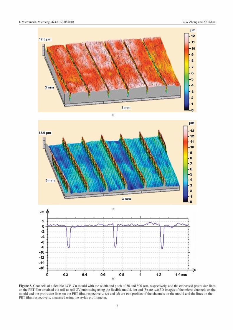
Figure 8. Channels of a flexible LCP–Cu mould with the width and pitch of 50 and 500 μm, respectively, and the embossed protrusive lineson the PET film obtained via roll-to-roll UV embossing using the flexible mould. (a) and (b) are two 3D images of the micro-channels on themould and the protrusive lines on the PET film, respectively; (c) and (d) are two profiles of the channels on the mould and the lines on thePET film, respectively, measured using the stylus profilometer.
7

J. Micromech. Microeng. 22 (2012) 085010 Z W Zhong and X C Shan
(d)
Figure 8. (Continued.)
pattern, the etching depth can be controlled by the etchingperiod.
Figure 5(a) demonstrates a fabricated flexible mould. Thecopper foil was etched to the bottom and the LCP foil wasexposed, so that microstructures with a vertical height of36 μm could be obtained. In our actual UV embossing, theCu etching was stopped when the etching depth reached about15 μm, leaving a residual copper layer of about 20 μm inorder to increase the strength of the flexible mould. The sizeof the LCP–Cu mould was 400 mm × 300 mm. Hence, twopieces of such patterned films were tiled and wrapped aroundthe embossing roller to form the flexible mould. The LCP–Cumould was attached on a metal roller as shown in figure 5(b),via a double-sided adhesive tape, which is a method often usedin flexo-printing. The mould contained micro-scale patterns tobe embossed onto the resin coating on the film substrate.
The diameter of the embossing roll is 160 mm. If thethickness (0.5 mm) of a double-sided tape is considered,the circumference of the embossing roll is 505.8 mm. Thesize of a fabricated flexible mould was 400 mm (roll axisdirection) × 300 mm (roll circumference direction). Hence,two pieces of the fabricated flexible mould need to be cut andtiled precisely in order to attach them around the roll withminimum seam. Because the lateral and vertical dimensionsof each micro-pattern on the mould are sub-millimeter scales,the changes in the dimensions and shapes of the patterns onthe flexible mould before and after it is attached to the roll canbe neglected.
The UV lamp was located directly under the embossingroller. This configuration allows simultaneous embossing andcuring of the liquid resin, increasing the production speed.Profiles including 3D surfaces of the embossed patterns andtheir corresponding mould patterns were evaluated using astylus profilometer. These 3D surfaces were then compared todetermine the quality and fidelity of the embossed patterns,which are reported in the following section. The stylusprofilometer used is Form Talysurf Series 2 from TaylorHobson, which can be used for 3D and 2D measurementsof embossed profiles.
3. Mould characterization and embossing results
Figures 6(a) and (c) show the micro-channel array patterned ona LCP–Cu flexible mould. The width and pitch of the micro-channels are 100 and 500 μm, respectively. It can be seenfrom figure 6(c) that the average depth of the micro-channelsis 12 μm measured using the stylus profilometer. Figures 6(b)and (d) show the embossed protrusive lines on a PET filmobtained via roll-to-roll UV embossing using the LCP–Cumould. The embossed protrusive lines replicated the profilesof the micro-channels precisely, with the width and pitch of 100and 500 μm, respectively. The height of the embossed linesranged from 11.5 to 12 μm, with a fidelity error < −4.2% inthe vertical direction.
Figures 7(a) and (c) show the micro-channels of anotherflexible LCP–Cu mould. The width and pitch of the micro-channels are 200 and 500 μm, respectively. It can be seenfrom figure 7(c) that the average depth of the micro-channelsis 15 μm measured using the stylus profilometer. Figures 7(b)and (d) show the embossed protrusive lines on the PET filmobtained via roll-to-roll UV embossing using this LCP–Cumould. The embossed line heights agreed well with the linedepths of the patterns on the mould with the width and pitchof 200 and 500 μm, respectively. The height of the embossedlines ranged from 14.5 to 15 μm, with a fidelity error < −3.4%in the vertical direction.
Figures 8 (a) and (c) show the channels of another flexibleLCP–Cu mould, and figures 8(b) and (d) show the embossedprotrusive lines on the PET film obtained via roll-to-roll UVembossing using this LCP–Cu mould. Figures 9(a) and (b)show the SEM images of the channels of the flexible mouldand the embossed protrusive lines on the film obtained viaembossing using the mould, respectively. Both the embossedline heights and channel widths coincided with the channeldepths and widths on the mould. The embossed protrusivelines replicated the profiles of the channels precisely, with thewidth and pitch of 50 and 500 μm, respectively. The height ofthe embossed lines ranged from 8.5 to 9 μm, with a fidelityerror < −5.6% in the vertical direction.
8

J. Micromech. Microeng. 22 (2012) 085010 Z W Zhong and X C Shan
(a)
(b)
Figure 9. SEM images of the channels of (a) the flexible LCP–Cu mould with the width and pitch of 50 and 500 μm, respectively, and(b) the embossed protrusive lines on the PET film obtained via roll-to-roll UV embossing using the flexible mould.
Figures 10(a) and (c) show the holes on a flexible LCP–Cu mould, and figures 10(b) and (d) show the embossed dotpillars on the PET film obtained via roll-to-roll UV embossingusing this LCP–Cu mould. The embossed dot pillars replicated
the profiles of the holes precisely, with the diameter and pitchof 400 and 1000 μm, respectively. The height of the embosseddot pillars ranged from 16 to 16.5 μm, with an average fidelityerror in depth < −3.1%.
9

J. Micromech. Microeng. 22 (2012) 085010 Z W Zhong and X C Shan
(a)
(b)
(c)
Figure 10. Holes on a flexible LCP–Cu mould with the diameter and pitch of 400 and 1000 μm, respectively, and the embossed dot pillarson the PET film obtained via roll-to-roll UV embossing using the flexible mould. (a) and (b) are two 3D images of the micro-holes on themould and the dot pillars on the PET film, respectively; (c) and (d) are two profiles of the micro-holes and the pillars on the mould and thePET film, respectively, measured using the stylus profilometer.
10

J. Micromech. Microeng. 22 (2012) 085010 Z W Zhong and X C Shan
(d )
Figure 10. (Continued.)
4. Conclusions
Flexible moulds were fabricated from a hybrid film substratemade of a liquid crystal polymer with double clad copper foils.The effective pattern area of the fabricated flexible mouldwas 400 mm × 300 mm with a minimal feature size of50 μm. Large-area roller embossing using the hybrid flexiblemould was demonstrated, and micro-features and structuressuch as micro-channels and dot arrays were replicated onthermoplastic substrates. In addition to its ease and low cost infabrication, the hybrid flexible moulds demonstrated to haveacceptable fidelity and durability. The hybrid flexible mould isa novel solution for large-area roller embossing. The roll-to-roll embossing processes are capable of producing micro-scalestructures and functional devices over a large area at one time.
Acknowledgments
The authors would like to thank Dr Albert Lu, S J Wong andMohaime B Mohahidin for their assistance in slot die coatingand UV embossing.
References
[1] Gates B D, Xu Q B, Stewart M, Ryan D, Willson C Gand Whitesides G M 2005 New approaches tonanofabrication: molding, printing, and other techniquesChem. Rev. 105 1171–96
[2] Sotomayor Torres C M et al 2003 Nanoimprint lithography: analternative nanofabrication approach Mater. Sci. Eng. C23 23–31
[3] Guo L J 2004 Recent progress in nanoimprint technology andits applications J. Phys. D: Appl. Phys. 37 R123–41
[4] Guo L J 2007 Nanoimprint lithography: methods and materialrequirements Adv. Mater. 19 495–513
[5] Schift H 2008 Nanoimprint lithography: An old story inmodern times? A review J. Vac. Sci. Technol. B 26 458–80
[6] Ahn S H and Guo L J 2008 High-speed roll-to-rollnanoimprint lithography on flexible plastic substrates Adv.Mater. 20 2044–9
[7] Ahn S H and Guo L J 2009 Large-area roll-to-roll androll-to-plate nanoimprint lithography: a step toward
high-throughput application of continuous nanoimprintingACS Nano 3 2304–10
[8] Chou S Y, Krauss P R and Renstrom P J 1995 Imprint ofsub-25 nm vias and trenches in polymers Appl. Phys. Lett.67 3114–6
[9] Zhong Z W, Shan X C and Yao Y C 2010 Investigation ofantiadhesive coatings for nanoimprinting lithography Mater.Manuf. Process. 25 658–64
[10] Heckele M, Guber A E and Truckenmuller R 2006 Replicationand bonding techniques for integrated microfluidic systemsMicrosyst. Technol. 12 1031–5
[11] Shiu P P, Knopf G K, Ostojic M and Nikumb S 2008 Rapidfabrication of tooling for microfluidic devices via lasermicromachining and hot embossing J. Micromech.Microeng. 18 025012
[12] Li J M, Liu C, Qiao H C, Zhu L Y, Chen G and Dai X D 2008Hot embossing/bonding of a poly(ethylene terephthalate)(PET) microfluidic chip J. Micromech. Microeng.18 015008
[13] Ahn S, Cha J, Myung H, Kim S-m and Kang S 2006Continuous ultraviolet roll nanoimprinting process forreplicating large-scale nano- and micropatterns Appl. Phys.Lett. 89 213101
[14] Kololuoma T K, Tuomikoski M, Makela T, Heilmann J,Haring T, Kallioinen J, Hagberg J, Kettunen Iand Kopola H K 2004 Towards roll-to-roll fabrication ofelectronics, optics, and optoelectronics for smart andintelligent packaging Proc. SPIE 5363 77–85
[15] Velten T, Schuck H, Richter M, Klink G, Bock K, Malek C K,Roth S, Schoo H and Bolt P J 2008 Microfluidics on foil:state of the art and new developments Proc. Inst. Mech.Eng. B 222 107–16
[16] Nagato K, Sugimoto S, Hamaguchi T and Nakao M 2010Iterative roller imprint of multilayered nanostructuresMicroelectron. Eng. 87 1543–5
[17] Makela T, Haatainen T, Majander P and Ahopelto J 2007Continuous roll to roll nanoimprinting of inherentlyconducting polyaniline Microelectron. Eng. 84 877–9
[18] Krebs F C 2009 All solution roll-to-roll processed polymersolar cells free from indium-tin-oxide and vacuum coatingsteps Org. Electron. 10 761–8
[19] Yeo L P, Ng S H, Wang Z F, Xia H M, Wang Z P, Thang V S,Zhong Z W and de Rooij N F 2010 Investigation of hotroller embossing for microfluidic devices J. Micromech.Microeng. 20 015017
11

J. Micromech. Microeng. 22 (2012) 085010 Z W Zhong and X C Shan
[20] Zhong Z W, Shan X C and Wong S J 2011 Roll-to-rolllarge-format slot die coating of photosensitive resin for UVembossing Microsyst. Technol. 17 1703–11
[21] Becker H and Gartner C 2008 Polymer microfabricationtechnologies for microfluidic systems Anal. Bioanal. Chem.390 89–111
[22] Schift H, Halbeisen M, Schutz U, Delahoche B, Vogelsang Kand Gobrecht J 2006 Surface structuring of textile fibersusing roll embossing Microelectron. Eng. 83 855–8
[23] Chang C Y, Yang S Y and Sheh J L 2006 A roller embossingprocess for rapid fabrication of microlens arrays on glasssubstrates Microsyst. Technol. 12 754–9
[24] Jiang L T, Huang T C, Chang C Y, Ciou J R, Yang S Yand Huang P H 2008 Direct fabrication of rigidmicrostructures on a metallic roller using a dry film resistJ. Micromech. Microeng. 18 015004
[25] Ishizawa N, Idei K, Kimura T, Noda D and Hattori T 2008Resin micromachining by roller hot embossing Microsyst.Technol. 14 1381–8
[26] Shan X C, Soh Y C, Shi C W P, Jin L and Lu C W 2009 Amicro roller embossing process for structuring large-areasubstrates of laminated ceramic green tapes Microsyst.Technol. 15 1319–25
[27] Liu S J and Chang Y C 2007 A novel soft-mold rollerembossing method for the rapid fabrication of micro-blocks onto glass substrates J. Micromech. Microeng.17 172–9
[28] Park I, Lim S H, Shin D, Lee K S, Jang S, Yim H J, Won Cand Jeong J I 2009 Heat transfer analysis during a curingprocess for UV nanoimprint lithography J. Mech. Sci.Technol. 23 927–30
[29] Lee N Y and Kim Y S 2007 A poly(dimethylsiloxane)-coatedflexible mold for nanoimprint lithography Nanotechnology18 415303
[30] Lee N Y and Kim Y S 2007 A simple imprint method formulti-tiered polymer nanopatterning on large flexiblesubstrates employing a flexible mold and hemispherical
PDMS elastomer Macromol. Rapid Commun.28 1995–2000
[31] Zhang J, Cui B and Ge H X 2011 Fabrication of flexible moldfor hybrid nanoimprint-soft lithography Microelectron. Eng.88 2192–5
[32] Lee J, Park S, Choi K and Kim G 2008 Nano-scale patterningusing the roll typed UV-nanoimprint lithography toolMicroelectron. Eng. 85 861–5
[33] Lan S H, Song J H, Lee M G, Ni J, Lee N K and Lee H J 2010Continuous roll-to-flat thermal imprinting process forlarge-area micro-pattern replication on polymer substrateMicroelectron. Eng. 87 2596–601
[34] Weng Y J, Weng Y C, Yang S Y and Wong J L 2009 A novelelectromagnetism-assisted imprinting technology toreplicate microstructures onto a large-area curved surfaceusing a flexible magnetic mold Polym. Adv. Technol.20 92–7
[35] Hamouda F, Barbillon G, Gaucher F and Bartenlian B 2010Sub-200 nm gap electrodes by soft UV nanoimprintlithography using polydimethylsiloxane mold withoutexternal pressure J. Vac. Sci. Technol. B 28 82–5
[36] Koo N, Otto M, Kim J W, Jeong J H and Kurz H 2011 Pressand release imprint: control of the flexible molddeformation and the local variation of residual layerthickness in soft UV-NIL Microelectron. Eng. 88 1033–6
[37] Koo N, Plachetka U, Otto M, Bolten J, Jeong J H, Lee E Sand Kurz H 2008 The fabrication of a flexible mold for highresolution soft ultraviolet nanoimprint lithographyNanotechnology 19 225304
[38] Lee Y C, Chen B T, Wu T H and Chou Y Y 2012 Full wafermicrostructure fabrication by continuous UV-assisted rollerimprinting lithography to enhance light extraction of LEDsMicroelectron. Eng. 91 64–9
[39] McClelland G M, Hart M W, Rettner C T, Best M E,Carter K R and Terris B D 2002 Nanoscale patterning ofmagnetic islands by imprint lithography using a flexiblemold Appl. Phys. Lett. 81 1483–5
12