![Magnetic quasi-static simulation [coreless liquid-cooled motor]](https://static.fdocuments.net/doc/165x107/56816864550346895ddeb859/magnetic-quasi-static-simulation-coreless-liquid-cooled-motor.jpg)
Magnetic quasi-static simulation [coreless liquid-cooled motor]
Upload
vuongthienCategory
view
232download
7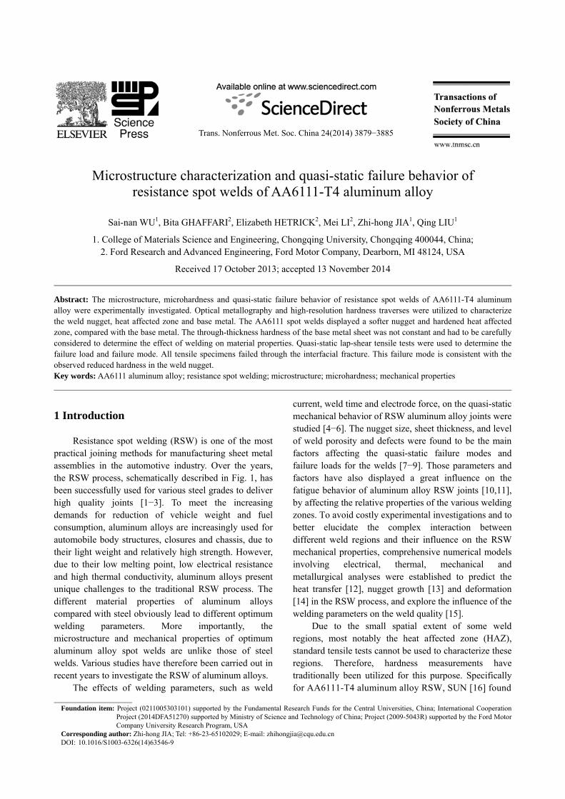
Trans. Nonferrous Met. Soc. China 24(2014) 3879−3885
Microstructure characterization and quasi-static failure behavior of
resistance spot welds of AA6111-T4 aluminum alloy
Sai-nan WU1, Bita GHAFFARI2, Elizabeth HETRICK2, Mei LI2, Zhi-hong JIA1, Qing LIU1
1. College of Materials Science and Engineering, Chongqing University, Chongqing 400044, China; 2. Ford Research and Advanced Engineering, Ford Motor Company, Dearborn, MI 48124, USA
Received 17 October 2013; accepted 13 November 2014
Abstract: The microstructure, microhardness and quasi-static failure behavior of resistance spot welds of AA6111-T4 aluminum alloy were experimentally investigated. Optical metallography and high-resolution hardness traverses were utilized to characterize the weld nugget, heat affected zone and base metal. The AA6111 spot welds displayed a softer nugget and hardened heat affected zone, compared with the base metal. The through-thickness hardness of the base metal sheet was not constant and had to be carefully considered to determine the effect of welding on material properties. Quasi-static lap-shear tensile tests were used to determine the failure load and failure mode. All tensile specimens failed through the interfacial fracture. This failure mode is consistent with the observed reduced hardness in the weld nugget. Key words: AA6111 aluminum alloy; resistance spot welding; microstructure; microhardness; mechanical properties 1 Introduction
Resistance spot welding (RSW) is one of the most practical joining methods for manufacturing sheet metal assemblies in the automotive industry. Over the years, the RSW process, schematically described in Fig. 1, has been successfully used for various steel grades to deliver high quality joints [1−3]. To meet the increasing demands for reduction of vehicle weight and fuel consumption, aluminum alloys are increasingly used for automobile body structures, closures and chassis, due to their light weight and relatively high strength. However, due to their low melting point, low electrical resistance and high thermal conductivity, aluminum alloys present unique challenges to the traditional RSW process. The different material properties of aluminum alloys compared with steel obviously lead to different optimum welding parameters. More importantly, the microstructure and mechanical properties of optimum aluminum alloy spot welds are unlike those of steel welds. Various studies have therefore been carried out in recent years to investigate the RSW of aluminum alloys.
The effects of welding parameters, such as weld
current, weld time and electrode force, on the quasi-static mechanical behavior of RSW aluminum alloy joints were studied [4−6]. The nugget size, sheet thickness, and level of weld porosity and defects were found to be the main factors affecting the quasi-static failure modes and failure loads for the welds [7−9]. Those parameters and factors have also displayed a great influence on the fatigue behavior of aluminum alloy RSW joints [10,11], by affecting the relative properties of the various welding zones. To avoid costly experimental investigations and to better elucidate the complex interaction between different weld regions and their influence on the RSW mechanical properties, comprehensive numerical models involving electrical, thermal, mechanical and metallurgical analyses were established to predict the heat transfer [12], nugget growth [13] and deformation [14] in the RSW process, and explore the influence of the welding parameters on the weld quality [15].
Due to the small spatial extent of some weld regions, most notably the heat affected zone (HAZ), standard tensile tests cannot be used to characterize these regions. Therefore, hardness measurements have traditionally been utilized for this purpose. Specifically for AA6111-T4 aluminum alloy RSW, SUN [16] found
Foundation item: Project (0211005303101) supported by the Fundamental Research Funds for the Central Universities, China; International Cooperation
Project (2014DFA51270) supported by Ministry of Science and Technology of China; Project (2009-5043R) supported by the Ford Motor Company University Research Program, USA
Corresponding author: Zhi-hong JIA; Tel: +86-23-65102029; E-mail: [email protected] DOI: 10.1016/S1003-6326(14)63546-9
Sai-nan WU, et al/Trans. Nonferrous Met. Soc. China 24(2014) 3879−3885
3880
Fig. 1 Schematic of resistance spot welding process that the HAZ was harder than both the base metal and the nugget, which themselves had a similar hardness. However, SHI and GUO [17] found that the base metal was harder than the HAZ, which was in turn harder than the nugget. Such inconsistencies in the literature regarding the various weld properties are also seen for other aluminum alloys, and should be addressed.
In the present work, the microstructure, microhardness and quasi-static failure behavior of AA6111-T4 aluminum alloy RSW joints were studied. Optical metallography and high-resolution hardness traverses were utilized to characterize the weld nugget, HAZ and base metal. The aim of this study is to obtain a better understanding of the aluminum alloy RSW microstructure and mechanical properties, and how the local properties might influence the weld failure behavior. 2 Experimental 2.1 Materials
Commercial aluminum alloy AA6111-T4 sheets of 2 mm in thickness with surface pretreatment and lubrication were utilized. Table 1 shows the nominal composition of AA6111 alloy, as well as the mechanical properties that were measured for the as-received sheets. Three standard ASTM tensile test specimens were used to obtain the average mechanical properties, 0.2% offset
yield strength (YS), ultimate tensile strength (UTS) and elongation to fracture (EL), which are consistent with the nominal values. 2.2 Spot welding process
The Al sheets were cut into 95 mm × 25 mm coupons and joined in a lap-shear configuration with a 25 mm overlap. A multi-step medium-frequency direct current welding process with varying current, welding time and force level was used to produce two distinct weld strengths by targeting teardown button diameters of <4t1/2 and 5t1/2, where t was the governing metal thickness of the joint. Once the appropriate welding processing parameters were determined, several specimens were peeled to failure, to confirm the process robustness. Also, the specimens welded immediately before and after each set of 5 specimens characterized in this study were peeled to failure, displaying an average peel button diameter of 4.6 mm and 7.3 mm for the <4t1/2 and 5t1/2 specimens, respectively, with a range of <0.5 mm. 2.3 Specimen preparation and testing
Of the five specimens studied for each target button diameter, two specimens were used for microstructure characterization and microhardness measurements, and three for quasi-static lap-shear tensile testing.
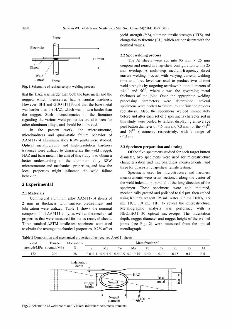
Specimens used for microstructure and hardness measurements were cross-sectioned along the center of the weld indentation, parallel to the long direction of the specimen. These specimens were cold mounted, mechanically ground and polished to 0.5 μm, then etched using Keller’s reagent (95 mL water, 2.5 mL HNO3, 1.5 mL HCl, 1.0 mL HF) to reveal the microstructure. Metallographic analysis was performed with a NEOPHOT 30 optical microscope. The indentation depth, nugget diameter and nugget height of the welded joints (see Fig. 2) were measured from the optical metallographs.
Table 1 Composition and mechanical properties of as-received AA6111 sheets
Mass fraction/% Yield strength/MPa
Tensile strength/MPa
Elongation/ % Si Mg Cu Mn Fe Cr Zn Ti Al
172 290 28 0.6−1.1 0.5−1.0 0.5−0.9 0.1−0.45 0.40 0.10 0.15 0.10 Bal.
Fig. 2 Schematic of weld zones and Vickers microhardness measurements
Sai-nan WU, et al/Trans. Nonferrous Met. Soc. China 24(2014) 3879−3885
3881
Vickers microhardness measurements were carried out before the specimens were etched, by a LECO AMH43 hardness testing system under a 200 g load with the indentations spaced 100 μm apart. Prior hardness measurements conducted on similar samples were utilized to optimize the indentation spacing, ensuring that it is sufficiently large to obtain accurate measure of the hardness, while providing the desired high-resolution traverses. Measurements on each specimen were taken in two directions, on a diagonal through the base metal, HAZ and nugget, as well as through the sheet thickness in the base metal far away from the nugget, as displayed in Fig. 2. In total, 32 through-thickness hardness traverses, eight from each of the cross-sectioned specimens, were obtained.
To evaluate the mechanical strength of the spot welded joints, quasi-static lap-shear tensile tests were done at a constant cross-head speed of 10 mm/min, with a SHIMADZU AG-X universal testing machine. During testing, 2 mm-thick shims were utilized to center the specimen, i.e. the nugget, along the load direction, to maintain the shear character of the test as long as possible. The joint failure load and the diameter of the fracture area were measured for the three specimens. 3 Results and discussion 3.1 Weld morphology and microstructure
characterization Figures 3(a) and 4(a) show the macrostructures of
the <4t1/2 and 5t1/2 specimens, respectively. The measured nugget diameter, nugget height and indentation depth of
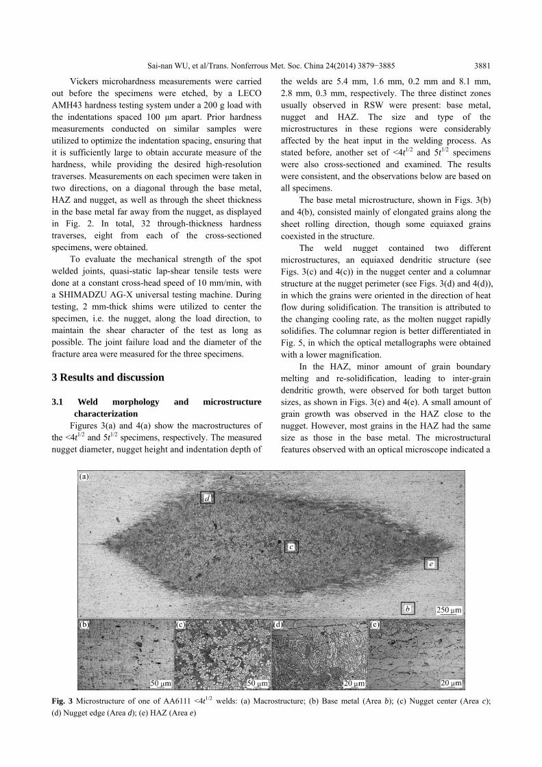
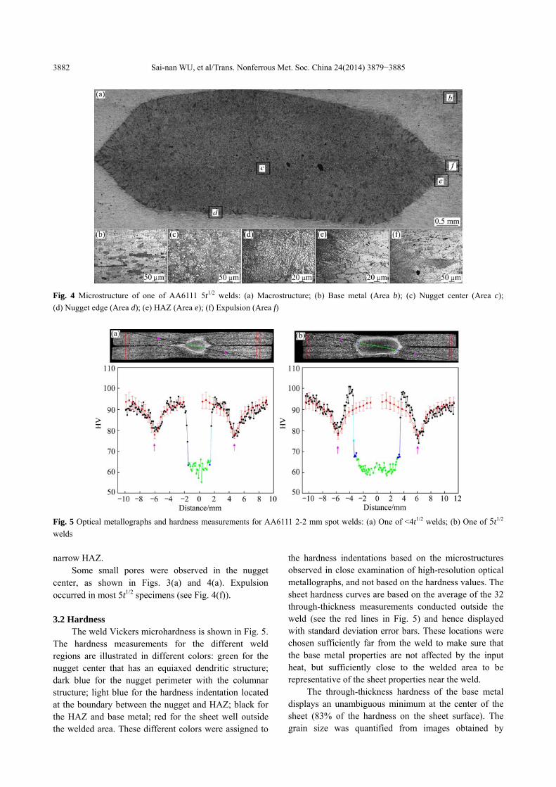
the welds are 5.4 mm, 1.6 mm, 0.2 mm and 8.1 mm, 2.8 mm, 0.3 mm, respectively. The three distinct zones usually observed in RSW were present: base metal, nugget and HAZ. The size and type of the microstructures in these regions were considerably affected by the heat input in the welding process. As stated before, another set of <4t1/2 and 5t1/2 specimens were also cross-sectioned and examined. The results were consistent, and the observations below are based on all specimens.
The base metal microstructure, shown in Figs. 3(b) and 4(b), consisted mainly of elongated grains along the sheet rolling direction, though some equiaxed grains coexisted in the structure.
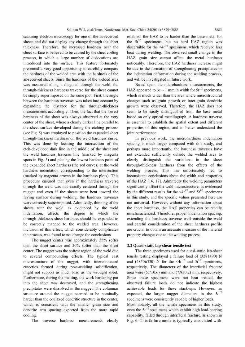
The weld nugget contained two different microstructures, an equiaxed dendritic structure (see Figs. 3(c) and 4(c)) in the nugget center and a columnar structure at the nugget perimeter (see Figs. 3(d) and 4(d)), in which the grains were oriented in the direction of heat flow during solidification. The transition is attributed to the changing cooling rate, as the molten nugget rapidly solidifies. The columnar region is better differentiated in Fig. 5, in which the optical metallographs were obtained with a lower magnification.
In the HAZ, minor amount of grain boundary melting and re-solidification, leading to inter-grain dendritic growth, were observed for both target button sizes, as shown in Figs. 3(e) and 4(e). A small amount of grain growth was observed in the HAZ close to the nugget. However, most grains in the HAZ had the same size as those in the base metal. The microstructural features observed with an optical microscope indicated a
Fig. 3 Microstructure of one of AA6111 <4t1/2 welds: (a) Macrostructure; (b) Base metal (Area b); (c) Nugget center (Area c); (d) Nugget edge (Area d); (e) HAZ (Area e)
Sai-nan WU, et al/Trans. Nonferrous Met. Soc. China 24(2014) 3879−3885
3882
Fig. 4 Microstructure of one of AA6111 5t1/2 welds: (a) Macrostructure; (b) Base metal (Area b); (c) Nugget center (Area c); (d) Nugget edge (Area d); (e) HAZ (Area e); (f) Expulsion (Area f)
Fig. 5 Optical metallographs and hardness measurements for AA6111 2-2 mm spot welds: (a) One of <4t1/2 welds; (b) One of 5t1/2 welds narrow HAZ.
Some small pores were observed in the nugget center, as shown in Figs. 3(a) and 4(a). Expulsion occurred in most 5t1/2 specimens (see Fig. 4(f)). 3.2 Hardness
The weld Vickers microhardness is shown in Fig. 5. The hardness measurements for the different weld regions are illustrated in different colors: green for the nugget center that has an equiaxed dendritic structure; dark blue for the nugget perimeter with the columnar structure; light blue for the hardness indentation located at the boundary between the nugget and HAZ; black for the HAZ and base metal; red for the sheet well outside the welded area. These different colors were assigned to
the hardness indentations based on the microstructures observed in close examination of high-resolution optical metallographs, and not based on the hardness values. The sheet hardness curves are based on the average of the 32 through-thickness measurements conducted outside the weld (see the red lines in Fig. 5) and hence displayed with standard deviation error bars. These locations were chosen sufficiently far from the weld to make sure that the base metal properties are not affected by the input heat, but sufficiently close to the welded area to be representative of the sheet properties near the weld.
The through-thickness hardness of the base metal displays an unambiguous minimum at the center of the sheet (83% of the hardness on the sheet surface). The grain size was quantified from images obtained by
Sai-nan WU, et al/Trans. Nonferrous Met. Soc. China 24(2014) 3879−3885
3883
scanning electron microscopy for one of the as-received sheets and did not display any change through the sheet thickness. Therefore, the increased hardness near the sheet surface is believed to be caused by the sheet coiling process, in which a large number of dislocations are introduced into the surface. This feature fortunately presented a very good opportunity to carefully compare the hardness of the welded area with the hardness of the as-received sheets. Since the hardness of the welded area was measured along a diagonal through the weld, the through-thickness hardness traverse for the sheet cannot be simply superimposed on the same plot. First, the angle between the hardness traverses was taken into account by expanding the distance for the through-thickness measurements accordingly. Then, the fact that the lowest hardness of the sheet was always observed at the very center of the sheet, where a clearly darker line parallel to the sheet surface developed during the etching process (see Fig. 5) was employed to position the expanded sheet through-thickness hardness on the weld hardness curve. This was done by locating the intersection of the etch-developed dark line in the middle of the sheet and the weld hardness traverse line (marked by magenta spots in Fig. 5) and placing the lowest hardness point of the expanded sheet hardness (the red curves) at the weld hardness indentation corresponding to the intersection (marked by magenta arrows in the hardness plots). This procedure ensured that even if the hardness traverse through the weld was not exactly centered through the nugget and even if the sheets were bent toward the faying surface during welding, the hardness traverses were correctly superimposed. Admittedly, thinning of the sheets near the weld, as evidenced by the weld indentation, affects the degree to which the through-thickness sheet hardness should be expanded to be correctly mapped to the welded area. However, inclusion of this effect, which considerably complicates the process, was found to not change the conclusions.
The nugget center was approximately 35% softer than the sheet surface and 20% softer than the sheet center. The nugget was the softest region of the weld due to several compounding effects. The typical cast microstructure of the nugget, with interconnected eutectics formed during post-welding solidification, might not support as much load as the wrought sheet. Furthermore, during the melting, the work hardening put into the sheet was destroyed, and the strengthening precipitates were dissolved in the nugget. The columnar structure around the nugget seemed to be nominally harder than the equiaxed dendritic structure in the center, which is consistent with the smaller grain size and dendrite arm spacing expected from the more rapid cooling.
The traverse hardness measurements clearly
establish the HAZ to be harder than the base metal for the 5t1/2 specimens, but no hard HAZ region was discernible for the <4t1/2 specimens, which received less heat during welding. The observed small change in the HAZ grain size cannot affect the metal hardness noticeably. Therefore, the HAZ hardness increase might be due to the formation of strengthening precipitates or the indentation deformation during the welding process, and will be investigated in future work.
Based upon the microhardness measurements, the HAZ appeared to be ~ 1 mm in width for 5t1/2 specimens, which is much wider than the area where microstructural changes such as grain growth or inter-grain dendritic growth were observed. Therefore, the HAZ does not seem to be easily distinguished from the base metal based on only optical metallograph. A hardness traverse is essential to establish the spatial extent and different properties of this region, and to better understand the joint performance.
In previous work, the microhardness indentation spacing is much larger compared with this study, and perhaps more importantly, the hardness traverses have not extended sufficiently outside the welded area to clearly distinguish the variations in the sheet through-thickness hardness from the effects of the welding process. This has unfortunately led to inconsistent conclusions about the width and properties of the HAZ [16, 17]. Admittedly the welding parameters significantly affect the weld microstructure, as evidenced by the different results for the <4t1/2 and 5t1/2 specimens in this study, and the specific values presented here are not universal. However, without any information about the sheet hardness, the HAZ properties can be readily mischaracterized. Therefore, proper indentation spacing, extending the hardness traverse well outside the weld and careful consideration of the sheet hardness profile are crucial to obtain an accurate measure of the material property changes due to the welding process. 3.3 Quasi-static lap-shear tensile test
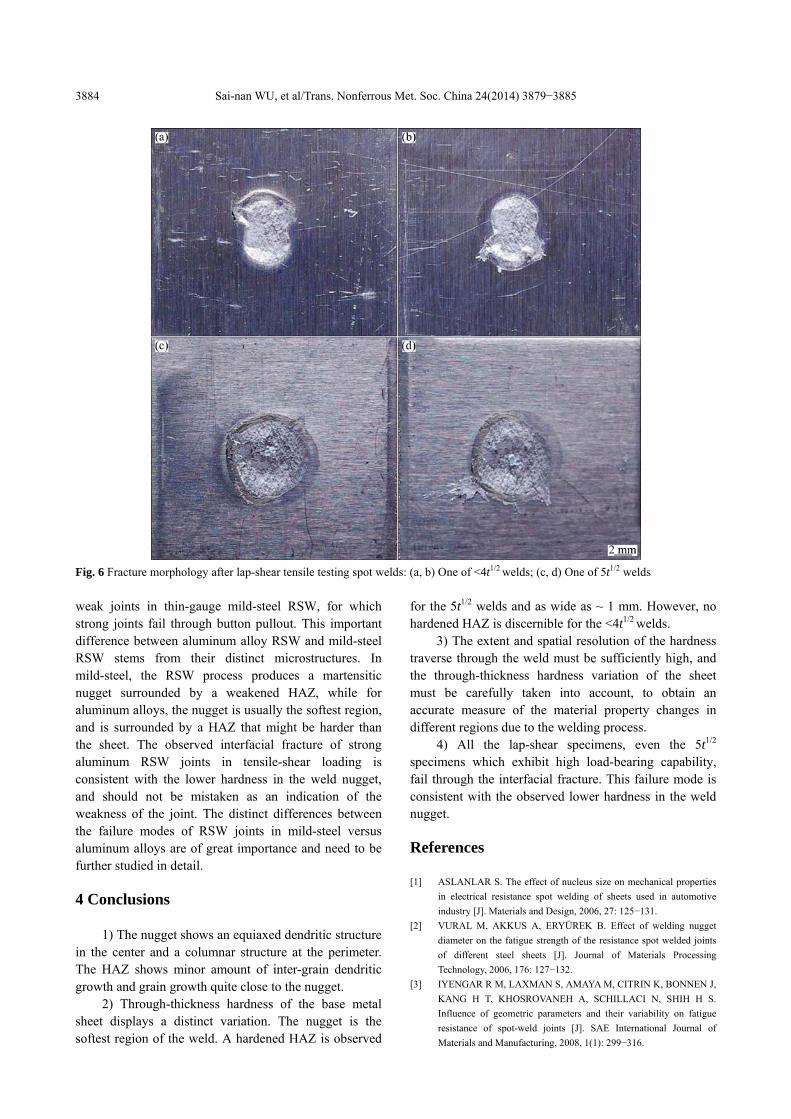
The three specimens used for quasi-static lap-shear tensile testing displayed a failure load of (3281±90) N and (4850±330) N for the <4t1/2 and 5t1/2 specimens, respectively. The diameters of the interfacial fracture area were (5.7±0.6) mm and (7.9±0.2) mm, respectively. Since these specimens were not heat treated, the observed failure loads do not indicate the highest achievable loads for these stack-ups. However, as expected, the larger nugget diameters in the 5t1/2 specimens were consistently capable of higher loads. Most notably, all the tensile specimens in this study, even the 5t1/2 specimens which exhibit high load-bearing capability, failed through interfacial fracture, as shown in Fig. 6. This failure mode is typically associated with
Sai-nan WU, et al/Trans. Nonferrous Met. Soc. China 24(2014) 3879−3885
3884
Fig. 6 Fracture morphology after lap-shear tensile testing spot welds: (a, b) One of <4t1/2 welds; (c, d) One of 5t1/2 welds weak joints in thin-gauge mild-steel RSW, for which strong joints fail through button pullout. This important difference between aluminum alloy RSW and mild-steel RSW stems from their distinct microstructures. In mild-steel, the RSW process produces a martensitic nugget surrounded by a weakened HAZ, while for aluminum alloys, the nugget is usually the softest region, and is surrounded by a HAZ that might be harder than the sheet. The observed interfacial fracture of strong aluminum RSW joints in tensile-shear loading is consistent with the lower hardness in the weld nugget, and should not be mistaken as an indication of the weakness of the joint. The distinct differences between the failure modes of RSW joints in mild-steel versus aluminum alloys are of great importance and need to be further studied in detail. 4 Conclusions
1) The nugget shows an equiaxed dendritic structure in the center and a columnar structure at the perimeter. The HAZ shows minor amount of inter-grain dendritic growth and grain growth quite close to the nugget.
2) Through-thickness hardness of the base metal sheet displays a distinct variation. The nugget is the softest region of the weld. A hardened HAZ is observed
for the 5t1/2 welds and as wide as ~ 1 mm. However, no hardened HAZ is discernible for the <4t1/2 welds.
3) The extent and spatial resolution of the hardness traverse through the weld must be sufficiently high, and the through-thickness hardness variation of the sheet must be carefully taken into account, to obtain an accurate measure of the material property changes in different regions due to the welding process.
4) All the lap-shear specimens, even the 5t1/2
specimens which exhibit high load-bearing capability, fail through the interfacial fracture. This failure mode is consistent with the observed lower hardness in the weld nugget. References [1] ASLANLAR S. The effect of nucleus size on mechanical properties
in electrical resistance spot welding of sheets used in automotive industry [J]. Materials and Design, 2006, 27: 125−131.
[2] VURAL M, AKKUS A, ERYÜREK B. Effect of welding nugget diameter on the fatigue strength of the resistance spot welded joints of different steel sheets [J]. Journal of Materials Processing Technology, 2006, 176: 127−132.
[3] IYENGAR R M, LAXMAN S, AMAYA M, CITRIN K, BONNEN J, KANG H T, KHOSROVANEH A, SCHILLACI N, SHIH H S. Influence of geometric parameters and their variability on fatigue resistance of spot-weld joints [J]. SAE International Journal of Materials and Manufacturing, 2008, 1(1): 299−316.
Sai-nan WU, et al/Trans. Nonferrous Met. Soc. China 24(2014) 3879−3885
3885
[4] FLOREA R S, SOLANKI K N, HAMMI Y, BAMMANN D J, CASTANIER M P. An experimental study of mechanical behavior of resistance spot welded aluminum 6061-T6 joints [C]//Proceedings of the ASME International Mechanical Engineering Congress and Exposition. Vancouver, 2010: 37−43.
[5] HASSANIFARD S, ZEHSAZ M, TOHGO K. The effects of electrode force on the mechanical behaviour of resistance spot-welded 5083-O aluminium alloy joints [J]. Strain, 2011, 47(1): 196−204.
[6] PEREIRA A M, FERREIRA J M, LOUREIRO A, COSTA J D M, BÁRTOLO P J. Effect of process parameters on the strength of resistance spot welds in 6082-T6 aluminium alloy [J]. Materials and Design, 2010, 31: 2454−2463.
[7] SUN X, STEPHENS E, DAVIES R, KHALEEL M, SPINELLA D J. Effects of failure modes on strength of aluminum resistance spot welds [J]. SAE Transactions: Journal of Materials and Manufacturing, 2006, 114: 493−502.
[8] SUN X, STEPHENS E V, DAVIES R W, KHALEEL M A, SPINELLA D J. Effects of fusion zone size on failure modes and static strength of aluminum resistance spot welds [J]. Welding Journal, 2004, 83(11): 308−318.
[9] AFSHARI D, SEDIGHI M, BARSOUM Z, PENG R L. An approach in prediction of failure in resistance spot welded aluminum 6061-T6 under quasi-static tensile test [J]. Proceedings of the Institution of Mechanical Engineers, Part B: Journal of Engineering Manufacture, 2012, 226(6): 1026−1032.
[10] FLOREA R S, BAMMANN D J, YELDELL A, SOLANKI K N,
HAMMIA Y. Welding parameters influence on fatigue life and microstructure in resistance spot welding of 6061-T6 aluminum alloy [J]. Materials and Design, 2013, 45: 456−465.
[11] HAN L, THORNTON M, LI D, SHERGOLD M. Effect of governing metal thickness and stack orientation on weld quality and mechanical behaviour of resistance spot welding of AA5754 aluminium [J]. Materials and Design, 2011, 32(4): 2107−2114.
[12] KHAN J A, BROACH K, AREFIN KABIR A A S. Numerical thermal model of resistance spot welding in aluminum [J]. Journal of Thermophysics and Heat Transfer, 2000, 14(1): 88−95.
[13] XU L, KHAN J A. Nugget growth model for aluminum alloys during resistance spot welding [J]. Welding Journal, 1999, 78(11): 367−372.
[14] CAVALLI M N, THOULESS M D, YANG Q D. Cohesive-zone modelling of the deformation and fracture of spot-welded joints [J]. Fatigue and Fracture of Engineering Materials and Structures, 2005, 28(10): 861−874.
[15] TAO Jian-feng, GONG Liang, LIU Cheng-liang, ZHAO Yang. Multi-field dynamic modeling and numerical simulation of aluminum alloy resistance spot welding [J]. Transactions of Nonferrous Metals Society of China, 2012, 22(12): 3066−3072.
[16] SUN X. Failure mechanisms of advanced welding processes [M]. Cambridge: Woodhead Publishing Limited, 2010: 35.
[17] SHI Y, GUO H. Fatigue performance and fatigue damage parameter estimation of spot welded joints of aluminium alloys 6111-T4 and 5754 [J]. Fatigue and Fracture of Engineering Materials and Structures, 2013, 36(10): 1081−1090.
AA6111 铝合金电阻点焊接头的微观组织特征和 准静态失效行为
吴赛楠 1,Bita GHAFFARI2,Elizabeth HETRICK2,Mei LI2,贾志宏 1,刘 庆 1
1. 重庆大学 材料科学与工程学院,重庆 400044;
2. Ford Research and Advanced Engineering, Ford Motor Company, Dearborn, MI 48124, USA
摘 要:对 AA6111 铝合金电阻点焊接头的显微组织、显微硬度和准静态失效行为进行分析。利用光学金相显微
技术和高分辨率硬度测量方法对接头的焊核区、热影响区和母材金属区进行表征。结果表明,焊核区的硬度低于
母材金属区的,热影响区的硬度高于或接近于母材金属区的。母材金属板材的硬度沿厚度方向发生变化,为准确
分析焊接工艺对接头性能的影响,这种变化需考虑在内。通过准静态搭接剪切试验得到焊接接头的失效载荷和失
效模式。所有接头以结合面断裂方式破坏,这种失效模式与焊核区的低硬度现象一致。
关键词:AA6111 铝合金;电阻点焊;显微组织;显微硬度;力学性能
(Edited by Xiang-qun LI)