Microstructure and Mechanical Properties of...
7
a Corresponding author: [email protected] Microstructure and Mechanical Properties of Austenitic Compacted Cast Iron with Additive Manganese K. M. Ahmad 1,a , M. R. Maarof 1 , M. Ishak 1 , M. S. Huzairi 1 1 Faculty of Mechanical Engineering, Universiti Malaysia Pahang, 26600 Pekan, Pahang, Malaysia, Abstract. High composition of austenitic matrix in microstructure is contributed to its special characteristic in reducing cracking and distortion. This special alloy will be in austenitic matrix when high temperature and also at room temperature which make it successful avoid matrix volume changes. In this study, austenitic compacted iron with minimum nickel contain of 12wt% is produced by using in-mould magnesium treatment. Magnesium Ferro Silicon (MgFeSi) used in determining the graphite form. Some of nickel replace by manganese in range of 9wt% to 12wt% Mn while Nickel remain at 12wt% Ni at all parameter. This research focuses on to investigate the effect of alloying elements on microstructure and mechanical properties. The outcome compared to standard of unmodified austenitic cast iron as in ASTM standard. The matrix obtained was all in austenitic matrix with the presence of compacted graphite distribution throughout the matrix. It is appeared that result shows increment of manganese at the centre region between graphite in the microstructure. It is occurred when percentage of manganese addition was increased. There are increases in hardness compared to unmodified austenitic iron. Tensile strength decreases when the manganese content increases in alloy. 1 Introduction Compacted Graphite cast iron (CGI) is also referred as vermicular graphite. It has inadvertently been produced in the past as a result of insufficient magnesium or cerium levels in molten intended to produce spheroidal graphite iron [1]. CGI with rounded ends graphite irons possesses mechanical properties intermediate between those of grey and ductile irons. Its unique properties have led it to be used in many applications which are unsuitable for grey or ductile iron especially in automotive industry. CGI has high fluidity and low solidification shrinkage, its tensile strength are around 1.5 – 2 times of gray cast iron [2]. In comparison with ductile cast iron (SGI), CGI has better damping properties, better thermal conductivity and good castability. Based on these characteristics CGI fulfils the requirements for many light weight constructions especially automotive engine blocks. However, modification levels of graphite must be controlled strictly in the CGI production. According to ASTM A842-85 standard requirement specifications for CGI castings state that the percentage of nodular graphite is 20% maximum and the formation of flake graphite must be avoided in the main parts of a casting [3,4]. In microstructure, 80% minimum of all graphite is needed to be in the form of compacted (vermicular) according to ASTM A247 (type IV) [5]. In recent years, there has been an increasing interest in Austenitic type of cast iron which can be an economic alternative to stainless steel as it is easier to cast and therefore suitable for precision casting of complicated shaped parts [6]. Therefore, austenitic cast iron also offers an outstanding combination of properties that meet a variety of industrial demands in withstanding the effects of corrosion, heat and wear [7]. However, so far to date there has been little attention given to Austenitic compacted iron (ACI) compared to austenitic gray iron (AGI) and Ductile Ni-resist (DNR). Most studies in ACI only been carried out in a small number of areas limited to compacted iron only (without austenitic matrix). So much so, there is no ASTM standard for this kind of special material. ACI is produced by taking a normal melt grey iron addition with controlling the carbon and silicon at lower levels by adding various alloys to produce a stable austenitic structure at ambient temperature. Controls of magnesium treatment and addition of anti-nodular element to the melt such as copper and Manganese very important to promote graphite in the form of compacted. Anti nodular agent will interfere in nodularisation process during solidification. Nickel cannot be neglects as the main alloying element who acts as austenitic promoter either in cast iron or ductile iron. Nickel becomes the DOI: 10.1051/ 00009 (2016) matecconf/2016 MATEC Web of Conferences 7400009 7 , 4 © The Authors, published by EDP Sciences. This is an open access article distributed under the terms of the Creative Commons Attribution License 4.0 (http://creativecommons.org/licenses/by/4.0/). ICMER 201 5
Transcript of Microstructure and Mechanical Properties of...
a Corresponding author: [email protected]
Microstructure and Mechanical Properties of Austenitic Compacted Cast Iron with Additive Manganese
K. M. Ahmad1,a, M. R. Maarof1, M. Ishak1, M. S. Huzairi1
1Faculty of Mechanical Engineering, Universiti Malaysia Pahang, 26600 Pekan, Pahang, Malaysia,
Abstract. High composition of austenitic matrix in microstructure is contributed to its special characteristic in reducing cracking and distortion. This special alloy will be in austenitic matrix when high temperature and also at room temperature which make it successful avoid matrix volume changes. In this study, austenitic compacted iron with minimum nickel contain of 12wt% is produced by using in-mould magnesium treatment. Magnesium Ferro Silicon (MgFeSi) used in determining the graphite form. Some of nickel replace by manganese in range of 9wt% to 12wt% Mn while Nickel remain at 12wt% Ni at all parameter. This research focuses on to investigate the effect of alloying elements on microstructure and mechanical properties. The outcome compared to standard of unmodified austenitic cast iron as in ASTM standard. The matrix obtained was all in austenitic matrix with the presence of compacted graphite distribution throughout the matrix. It is appeared that result shows increment of manganese at the centre region between graphite in the microstructure. It is occurred when percentage of manganese addition was increased. There are increases in hardness compared to unmodified austenitic iron. Tensile strength decreases when the manganese content increases in alloy.
1 Introduction Compacted Graphite cast iron (CGI) is also
referred as vermicular graphite. It has inadvertently been produced in the past as a result of insufficient magnesium or cerium levels in molten intended to produce spheroidal graphite iron [1]. CGI with rounded ends graphite irons possesses mechanical properties intermediate between those of grey and ductile irons. Its unique properties have led it to be used in many applications which are unsuitable for grey or ductile iron especially in automotive industry. CGI has high fluidity and low solidification shrinkage, its tensile strength are around 1.5 – 2 times of gray cast iron [2]. In comparison with ductile cast iron (SGI), CGI has better damping properties, better thermal conductivity and good castability. Based on these characteristics CGI fulfils the requirements for many light weight constructions especially automotive engine blocks.
However, modification levels of graphite must be controlled strictly in the CGI production. According to ASTM A842-85 standard requirement specifications for CGI castings state that the percentage of nodular graphite is 20% maximum and the formation of flake graphite must be avoided in the main parts of a casting [3,4]. In microstructure, 80% minimum of all graphite is needed to be in the form of compacted (vermicular) according to ASTM A247 (type IV) [5].
In recent years, there has been an increasing interest in Austenitic type of cast iron which can be an economic alternative to stainless steel as it is easier to cast and therefore suitable for precision casting of complicated shaped parts [6]. Therefore, austenitic cast iron also offers an outstanding combination of properties that meet a variety of industrial demands in withstanding the effects of corrosion, heat and wear [7]. However, so far to date there has been little attention given to Austenitic compacted iron (ACI) compared to austenitic gray iron (AGI) and Ductile Ni-resist (DNR). Most studies in ACI only been carried out in a small number of areas limited to compacted iron only (without austenitic matrix). So much so, there is no ASTM standard for this kind of special material.
ACI is produced by taking a normal melt grey iron addition with controlling the carbon and silicon at lower levels by adding various alloys to produce a stable austenitic structure at ambient temperature. Controls of magnesium treatment and addition of anti-nodular element to the melt such as copper and Manganese very important to promote graphite in the form of compacted. Anti nodular agent will interfere in nodularisation process during solidification. Nickel cannot be neglects as the main alloying element who acts as austenitic promoter either in cast iron or ductile iron. Nickel becomes the
DOI: 10.1051/00009 (2016) matecconf/2016MATEC Web of Conferences 74000097 ,4
© The Authors, published by EDP Sciences. This is an open access article distributed under the terms of the Creative Commons Attribution License 4.0 (http://creativecommons.org/licenses/by/4.0/).
ICMER 2015
principle reason why the casting alloy has an austenitic structure during solidification. With sufficient amount of alloy addition, an austenitic microstructure may occur and remained stable at room temperature.
Eventually, there are also suggestions using manganese and copper as austenitic matrix promoter since they have same function as nickel and at the same time they are cheaper than nickel. However the uses of manganese will promote carbide while cooper is strong anti nodular agent. Hence, this investigation will study manganese as one of the addition alloying element use together with nickel as austenitic stabilizer.
A consider amount of literature has been published describing role of manganese in cast iron austenitic stabilizer. Previous studies reported that manganese will promote carbide in cast iron during the solidification process. In ductile cast iron manganese will segregate at cell boundary [8-11]. In previous studies by different authors had found that, Instead of becomes a carbide formation manganese also effect the cast iron in nodularity [12].
Therefore, the aim of this study was to evaluate and validate the effect of manganese in austenitic compacted iron on mechanical properties and microstructure.
2 Experimental Set Up
2.1 Material preparation
The material used in this study is ACI. Sample preparation of 200 mm solid cylinder shape castings prepared by using a pattern as in figure 1. Materials will melt in the frequency induction furnace. Magnesium treatment used in the casting was applied using In The Mould Treatment Technique as it has high magnesium recovery percentage [13,14], by employing 1.0 Fe-Si-Mg in the reaction chamber. Experimental alloy of ACI divided into four groups as 9Mn-12Ni, 10Mn-12Ni, 11Mn-12Ni, 12Mn-12Ni wt%. Pure nickel and steel scrap were added into the furnace to increase Ni percentage and to control carbon content respectively. All charging material was melted in the induction furnace, during base material is melting Ferro manganese was added to the charging material in the furnace. The molten then stirred to make sure the alloyed elements smoothly diffused. The melt then was tapped using ladle before pouring into green sand mould.
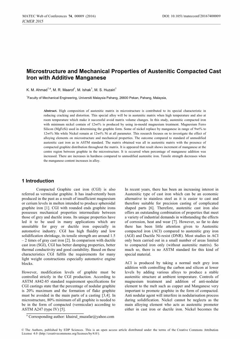
Figure 1: Solid cylinder shape castings pattern in this experiment (a) plan view (b) side view (c) front view (d) isometric view.
2.2 Mechanical test
Tensile test were carried out using universal testing machine 50 kN was used according to ASTM E8M at room temperature. CNC lathe machine was used to shape the cast alloy specimen to produce dog bone shape as shown in figure 2. The samples were further examined using scanning electron magnetic (SEM) to assess the microstructure after fracture. Samples from the specimens of 9wt%, 10wt%, 11wt% and 12wt% were taken for the hardness test. The Rockwell hardness test machine was used to determine the macro hardness. Five reading was taken from each sample and averaged. Every batch of samples was named according to its manganese weight percentage (wt %) temperature.
2.3 Microstructure analysis
Optical Microscopic (OM) and SEM were used for the microstructural characterization of the casting. Metallographic samples were cut from the broken halves of the tensile specimen. Microstructural analysis was come out using optical microscope model OLYMPUS BX60F5, while fractographic and fracture conducted using scanning electron microscopic model PHILIPS XL40.
Reaction chamber
(b)
(c) (d)
(a)
2
DOI: 10.1051/00009 (2016) matecconf/2016MATEC Web of Conferences 74000097 ,4
ICMER 2015
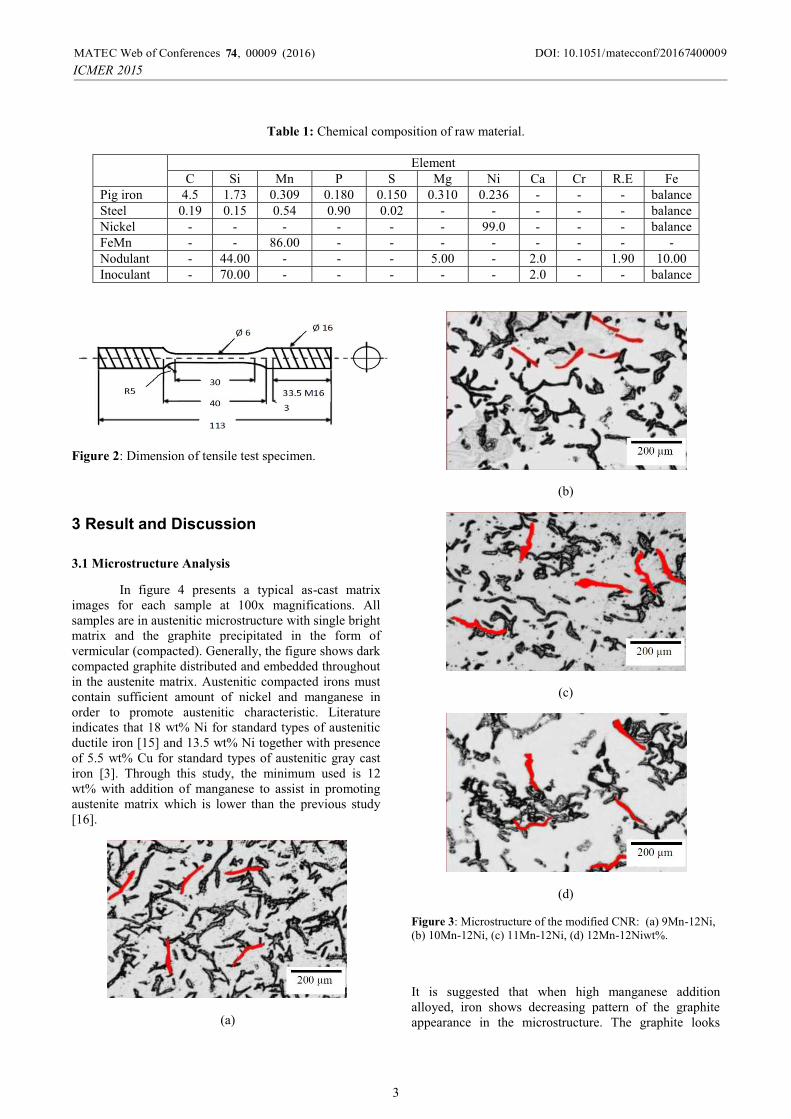
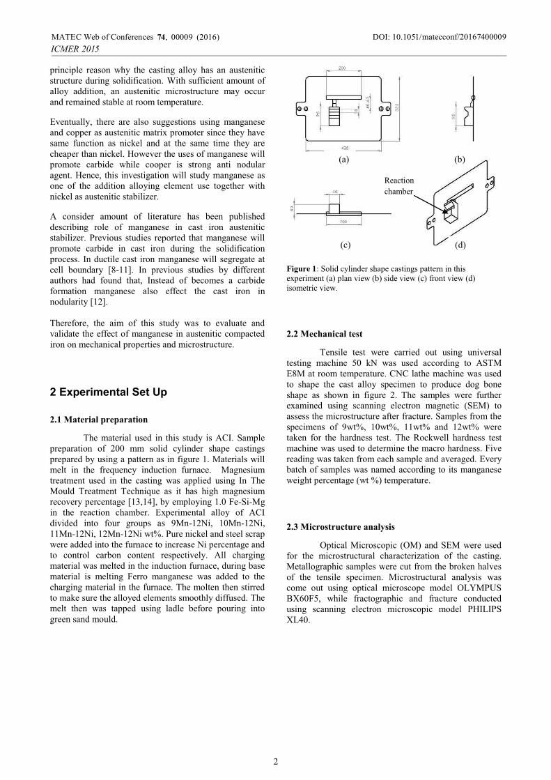
Table 1: Chemical composition of raw material.
ElementC Si Mn P S Mg Ni Ca Cr R.E Fe
Pig iron 4.5 1.73 0.309 0.180 0.150 0.310 0.236 - - - balanceSteel 0.19 0.15 0.54 0.90 0.02 - - - - - balanceNickel - - - - - - 99.0 - - - balanceFeMn - - 86.00 - - - - - - - -Nodulant - 44.00 - - - 5.00 - 2.0 - 1.90 10.00Inoculant - 70.00 - - - - - 2.0 - - balance
Figure 2: Dimension of tensile test specimen.
3 Result and Discussion
3.1 Microstructure Analysis
In figure 4 presents a typical as-cast matrix images for each sample at 100x magnifications. All samples are in austenitic microstructure with single bright matrix and the graphite precipitated in the form of vermicular (compacted). Generally, the figure shows dark compacted graphite distributed and embedded throughout in the austenite matrix. Austenitic compacted irons must contain sufficient amount of nickel and manganese in order to promote austenitic characteristic. Literature indicates that 18 wt% Ni for standard types of austenitic ductile iron [15] and 13.5 wt% Ni together with presence of 5.5 wt% Cu for standard types of austenitic gray cast iron [3]. Through this study, the minimum used is 12 wt% with addition of manganese to assist in promoting austenite matrix which is lower than the previous study [16].
(a)
(b)
(c)
(d)
Figure 3: Microstructure of the modified CNR: (a) 9Mn-12Ni, (b) 10Mn-12Ni, (c) 11Mn-12Ni, (d) 12Mn-12Niwt%.
It is suggested that when high manganese addition alloyed, iron shows decreasing pattern of the graphite appearance in the microstructure. The graphite looks
3
DOI: 10.1051/00009 (2016) matecconf/2016MATEC Web of Conferences 74000097 ,4
ICMER 2015
becomes distantly each other such as shown in figure 4(a) compared to figure 4(d). The formations of the carbide at this region push the graphite aside. It is making the length between graphite increases. Carbide formation will decrease the machinability of the iron and increase the production cost. Therefore it is preferred to be low in casting process. During the solidification of iron, manganese move away from the solid phase (graphite) which is first nucleate and solidifies. Manganese is the last element solidifies after the nucleation of graphite. It has been grouping and segregated away from the graphite. So, if the manganese increases the carbide will increase as suggested by Rasidi and Hasbullah [11]. This occurrences indicates segregated carbide suppress the existences of free graphite. Even though the combination of higher manganese wt% and less nickel wt% stabilized the austenite matrix, it is also appears that those combination promote carbide formation.
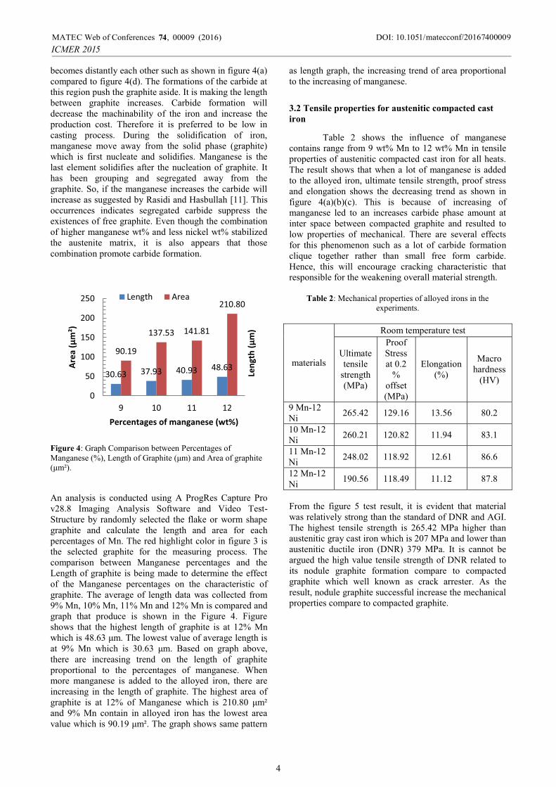
Figure 4: Graph Comparison between Percentages of Manganese (%), Length of Graphite (μm) and Area of graphite (μm²).
An analysis is conducted using A ProgRes Capture Pro v28.8 Imaging Analysis Software and Video Test-Structure by randomly selected the flake or worm shape graphite and calculate the length and area for each percentages of Mn. The red highlight color in figure 3 is the selected graphite for the measuring process. The comparison between Manganese percentages and the Length of graphite is being made to determine the effect of the Manganese percentages on the characteristic of graphite. The average of length data was collected from 9% Mn, 10% Mn, 11% Mn and 12% Mn is compared and graph that produce is shown in the Figure 4. Figure shows that the highest length of graphite is at 12% Mn which is 48.63 μm. The lowest value of average length is at 9% Mn which is 30.63 μm. Based on graph above, there are increasing trend on the length of graphite proportional to the percentages of manganese. When more manganese is added to the alloyed iron, there are increasing in the length of graphite. The highest area of graphite is at 12% of Manganese which is 210.80 μm² and 9% Mn contain in alloyed iron has the lowest area value which is 90.19 μm². The graph shows same pattern
as length graph, the increasing trend of area proportional to the increasing of manganese.
3.2 Tensile properties for austenitic compacted cast
iron
Table 2 shows the influence of manganese contains range from 9 wt% Mn to 12 wt% Mn in tensile properties of austenitic compacted cast iron for all heats. The result shows that when a lot of manganese is added to the alloyed iron, ultimate tensile strength, proof stress and elongation shows the decreasing trend as shown in figure 4(a)(b)(c). This is because of increasing of manganese led to an increases carbide phase amount at inter space between compacted graphite and resulted to low properties of mechanical. There are several effects for this phenomenon such as a lot of carbide formationclique together rather than small free form carbide. Hence, this will encourage cracking characteristic that responsible for the weakening overall material strength.
Table 2: Mechanical properties of alloyed irons in the experiments.
materials
Room temperature test
Ultimate tensile
strength (MPa)
Proof Stress at 0.2
%offset (MPa)
Elongation (%)
Macro hardness
(HV)
9 Mn-12Ni 265.42 129.16 13.56 80.2
10 Mn-12Ni 260.21 120.82 11.94 83.1
11 Mn-12Ni 248.02 118.92 12.61 86.6
12 Mn-12Ni 190.56 118.49 11.12 87.8
From the figure 5 test result, it is evident that material was relatively strong than the standard of DNR and AGI. The highest tensile strength is 265.42 MPa higher than austenitic gray cast iron which is 207 MPa and lower than austenitic ductile iron (DNR) 379 MPa. It is cannot be argued the high value tensile strength of DNR related to its nodule graphite formation compare to compacted graphite which well known as crack arrester. As theresult, nodule graphite successful increase the mechanical properties compare to compacted graphite.
30.63 37.93 40.93 48.63
90.19
137.53 141.81
210.80
0
50
100
150
200
250
9 10 11 12
Area
(μm
²)
Percentages of manganese (wt%)
Length Area
Leng
th (μ
m)
4
DOI: 10.1051/00009 (2016) matecconf/2016MATEC Web of Conferences 74000097 ,4
ICMER 2015
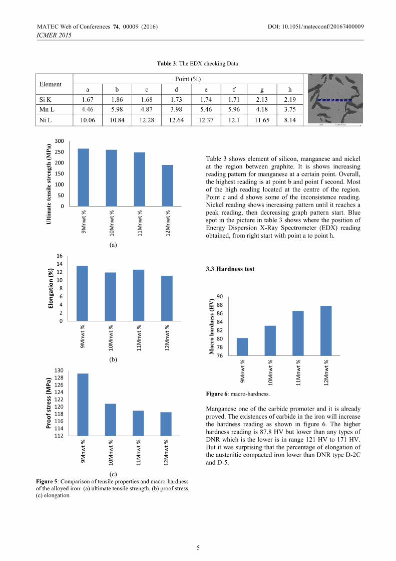
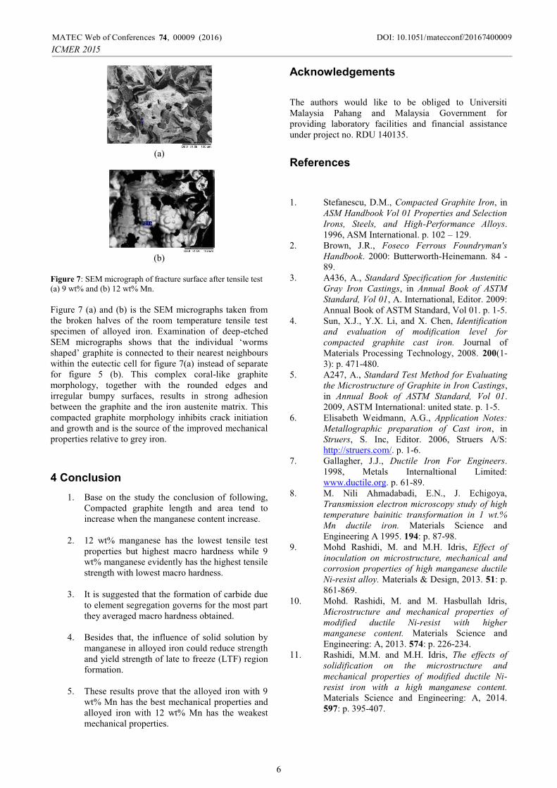
Table 3: The EDX checking Data.
ElementPoint (%)
a b c d e f g hSi K 1.67 1.86 1.68 1.73 1.74 1.71 2.13 2.19Mn L 4.46 5.98 4.87 3.98 5.46 5.96 4.18 3.75Ni L 10.06 10.84 12.28 12.64 12.37 12.1 11.65 8.14
(a)
(b)
(c) Figure 5: Comparison of tensile properties and macro-hardness of the alloyed iron: (a) ultimate tensile strength, (b) proof stress, (c) elongation.
Table 3 shows element of silicon, manganese and nickel at the region between graphite. It is shows increasing reading pattern for manganese at a certain point. Overall, the highest reading is at point b and point f second. Most of the high reading located at the centre of the region. Point c and d shows some of the inconsistence reading. Nickel reading shows increasing pattern until it reaches a peak reading, then decreasing graph pattern start. Blue spot in the picture in table 3 shows where the position of Energy Dispersion X-Ray Spectrometer (EDX) reading obtained, from right start with point a to point h.
3.3 Hardness test
Figure 6: macro-hardness.
Manganese one of the carbide promoter and it is already proved. The existences of carbide in the iron will increase the hardness reading as shown in figure 6. The higher hardness reading is 87.8 HV but lower than any types of DNR which is the lower is in range 121 HV to 171 HV. But it was surprising that the percentage of elongation of the austenitic compacted iron lower than DNR type D-2C and D-5.
0
50
100
150
200
250
300
9Mnw
t %
10M
nwt %
11M
nwt %
12M
nwt %
Ult
imate
ten
sile
str
eng
th (
MP
a)
02468
10121416
9Mnw
t %
10M
nwt %
11M
nwt %
12M
nwt %
Elon
gatio
n (%
)
112114116118120122124126128130
9Mnw
t %
10M
nwt %
11M
nwt %
12M
nwt %
Proo
f str
ess (
MPa
)
7678808284868890
9Mnw
t %
10M
nwt %
11M
nwt %
12M
nwt %
Macr
o h
ard
nes
s (H
V)
5
DOI: 10.1051/00009 (2016) matecconf/2016MATEC Web of Conferences 74000097 ,4
ICMER 2015
(a)
(b)
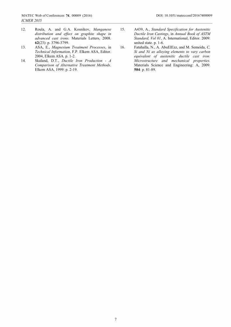
Figure 7: SEM micrograph of fracture surface after tensile test (a) 9 wt% and (b) 12 wt% Mn.
Figure 7 (a) and (b) is the SEM micrographs taken from the broken halves of the room temperature tensile test specimen of alloyed iron. Examination of deep-etched SEM micrographs shows that the individual ‘worms shaped’ graphite is connected to their nearest neighbours within the eutectic cell for figure 7(a) instead of separate for figure 5 (b). This complex coral-like graphite morphology, together with the rounded edges and irregular bumpy surfaces, results in strong adhesion between the graphite and the iron austenite matrix. This compacted graphite morphology inhibits crack initiation and growth and is the source of the improved mechanical properties relative to grey iron.
4 Conclusion 1. Base on the study the conclusion of following,
Compacted graphite length and area tend to increase when the manganese content increase.
2. 12 wt% manganese has the lowest tensile test properties but highest macro hardness while 9 wt% manganese evidently has the highest tensile strength with lowest macro hardness.
3. It is suggested that the formation of carbide due to element segregation governs for the most part they averaged macro hardness obtained.
4. Besides that, the influence of solid solution by manganese in alloyed iron could reduce strength and yield strength of late to freeze (LTF) region formation.
5. These results prove that the alloyed iron with 9 wt% Mn has the best mechanical properties and alloyed iron with 12 wt% Mn has the weakest mechanical properties.
Acknowledgements
The authors would like to be obliged to Universiti Malaysia Pahang and Malaysia Government for providing laboratory facilities and financial assistance under project no. RDU 140135.
References
1. Stefanescu, D.M., Compacted Graphite Iron, in ASM Handbook Vol 01 Properties and Selection
Irons, Steels, and High-Performance Alloys.1996, ASM International. p. 102 – 129.
2. Brown, J.R., Foseco Ferrous Foundryman's
Handbook. 2000: Butterworth-Heinemann. 84 - 89.
3. A436, A., Standard Specification for Austenitic
Gray Iron Castings, in Annual Book of ASTM
Standard, Vol 01, A. International, Editor. 2009: Annual Book of ASTM Standard, Vol 01. p. 1-5.
4. Sun, X.J., Y.X. Li, and X. Chen, Identification
and evaluation of modification level for
compacted graphite cast iron. Journal of Materials Processing Technology, 2008. 200(1-3): p. 471-480.
5. A247, A., Standard Test Method for Evaluating
the Microstructure of Graphite in Iron Castings,in Annual Book of ASTM Standard, Vol 01.2009, ASTM International: united state. p. 1-5.
6. Elisabeth Weidmann, A.G., Application Notes:
Metallographic preparation of Cast iron, in Struers, S. Inc, Editor. 2006, Struers A/S: http://struers.com/. p. 1-6.
7. Gallagher, J.J., Ductile Iron For Engineers.1998, Metals Internaltional Limited: www.ductile.org. p. 61-89.
8. M. Nili Ahmadabadi, E.N., J. Echigoya, Transmission electron microscopy study of high
temperature bainitic transformation in 1 wt.%
Mn ductile iron. Materials Science and Engineering A 1995. 194: p. 87-98.
9. Mohd Rashidi, M. and M.H. Idris, Effect of
inoculation on microstructure, mechanical and
corrosion properties of high manganese ductile
Ni-resist alloy. Materials & Design, 2013. 51: p. 861-869.
10. Mohd. Rashidi, M. and M. Hasbullah Idris, Microstructure and mechanical properties of
modified ductile Ni-resist with higher
manganese content. Materials Science and Engineering: A, 2013. 574: p. 226-234.
11. Rashidi, M.M. and M.H. Idris, The effects of
solidification on the microstructure and
mechanical properties of modified ductile Ni-
resist iron with a high manganese content.
Materials Science and Engineering: A, 2014. 597: p. 395-407.
6
DOI: 10.1051/00009 (2016) matecconf/2016MATEC Web of Conferences 74000097 ,4
ICMER 2015
12. Roula, A. and G.A. Kosnikov, Manganese
distribution and effect on graphite shape in
advanced cast irons. Materials Letters, 2008. 62(23): p. 3796-3799.
13. ASA, E., Magnesium Treatment Processes, in Technical Information, F.P. Elkem ASA, Editor. 2004, Elkem ASA. p. 1-2.
14. Skaland, D.T., Ductile Iron Production - A
Comparison of Alternative Treatment Methods.
Elkem ASA, 1999: p. 2-19.
15. A439, A., Standard Specification for Austenitic
Ductile Iron Castings, in Annual Book of ASTM
Standard, Vol 01, A. International, Editor. 2009: united state. p. 1-6.
16. Fatahalla, N., A. AbuElEzz, and M. Semeida, C,
Si and Ni as alloying elements to vary carbon
equivalent of austenitic ductile cast iron:
Microstructure and mechanical properties.
Materials Science and Engineering: A, 2009. 504: p. 81-89.
7
DOI: 10.1051/00009 (2016) matecconf/2016MATEC Web of Conferences 74000097 ,4
ICMER 2015