Microstructure and Mechanical Properties of Directionally...
36
Microstructure and Mechanical Properties of Directionally Solidified Ti-Fe Eutectic Alloy Rodrigo Contieri, Eder Lopes and Rubens Caram University of Campinas, Brazil Washington, DC October, 2012
Transcript of Microstructure and Mechanical Properties of Directionally...
Microstructure and Mechanical
Properties of Directionally Solidified
Ti-Fe Eutectic Alloy
Rodrigo Contieri, Eder Lopes and
Rubens Caram
University of Campinas, Brazil
Washington, DC
October, 2012

Campinas
Campinas, SP, Brazil
2

• Founded in 1966
• Strong tradition in
education and in
scientific research
(15% of the Brazilian
Scientific Production)
• 17,000 undergraduate
and 16,000 graduate
students
University of Campinas
3
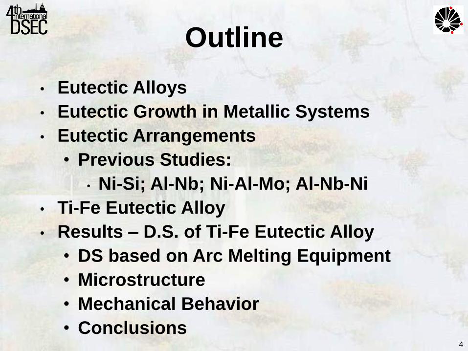
Outline
• Eutectic Alloys
• Eutectic Growth in Metallic Systems
• Eutectic Arrangements
• Previous Studies:
• Ni-Si; Al-Nb; Ni-Al-Mo; Al-Nb-Ni
• Ti-Fe Eutectic Alloy
• Results – D.S. of Ti-Fe Eutectic Alloy
• DS based on Arc Melting Equipment
• Microstructure
• Mechanical Behavior
• Conclusions
4

• Eutectic alloys allow the developing of in situ composite for structural applications
• This material consists of phases embedded in a matrix that do not dissolve in each other and are physically separated by a sharp interface between them
• This composite material provides the opportunity of merging the properties of distinct constituents into one material.
Eutectic Alloys
5

6
• Growth of eutectic alloys is an effective method in obtaining in situ composite materials
• In situ composites generally have a high degree of thermal stability and improved mechanical properties
• D.S. eutectic alloys results in regular structure of two or more solid phases
• Eutectic solidification leads to cooperative growth
Eutectic Growth
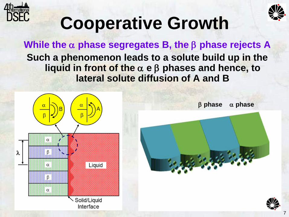
While the phase segregates B, the phase rejects A
Such a phenomenon leads to a solute build up in the liquid in front of the e phases and hence, to
lateral solute diffusion of A and B
phase
Cooperative Growth
phase
7

Growth of CBr4-C2Cl6 eutectic organic alloy
V Liquid Solid
Hot Cold
S/L Interface
J.D. Hunt and K.A. Jackson – Bell Laboratories – 60’s
Eutectic Growth
8

9
Previous Studies
Ni-Ni3Si - Lamellar
Al3Nb-Nb2Al - Lamellar
Ni-Al-Mo - Rod-like
Al3Nb-Nb2Al-AlNiNb - Ternary
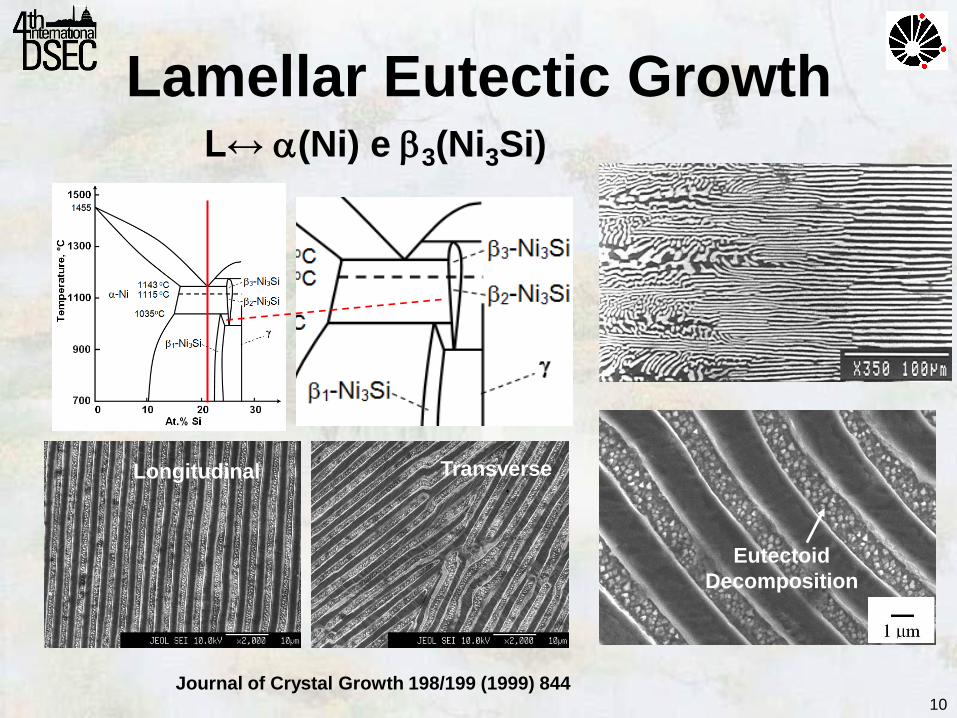
Lamellar Eutectic Growth L↔ (Ni) e 3(Ni3Si)
Longitudinal Transverse
Eutectoid
Decomposition
Journal of Crystal Growth 198/199 (1999) 844 10
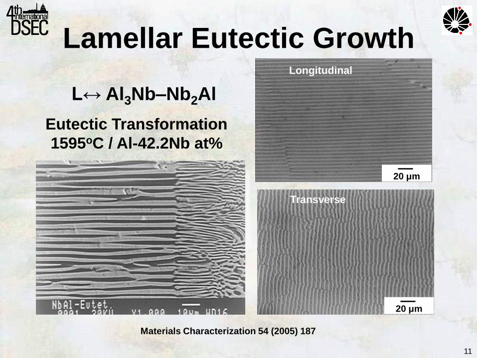
Lamellar Eutectic Growth
Materials Characterization 54 (2005) 187
Eutectic Transformation
1595oC / Al-42.2Nb at%
L↔ Al3Nb–Nb2Al
20 μm
20 μm
Longitudinal
Transverse
11

12
Rod-Like Eutectic Growth
Eutectic Transformation
1600oC / NiAl-10Mo at%
L↔ NiAl–Mo
Journal of Alloys and Compounds 381 (2004) 91
Longitudinal
Transverse

0 5 10 15 20 25Compressive Strain (%)
0
200
400
600
800
1000
1200
1400
1600
1800
Co
mp
res
siv
e S
tre
ss
(M
Pa
) NiAl-Mo (300 K)
NiAl (300 K)
NiAl-Mo (1273 K)
NiAl (1273 K)
NiAl-Mo In Situ Composite
NiAl Mo
Rod-Like Eutectic Growth
13

14
Ternary Eutectic Growth
Eutectic Transformation 1520oC / Al-40.4Nb-2.4Ni at% L↔ Al3Nb–Nb2Al-AlNbNi
Scripta Materialia 48 (2003) 1495

15
Ternary Eutectic Growth
Atom distribution by X-Ray Maps
16
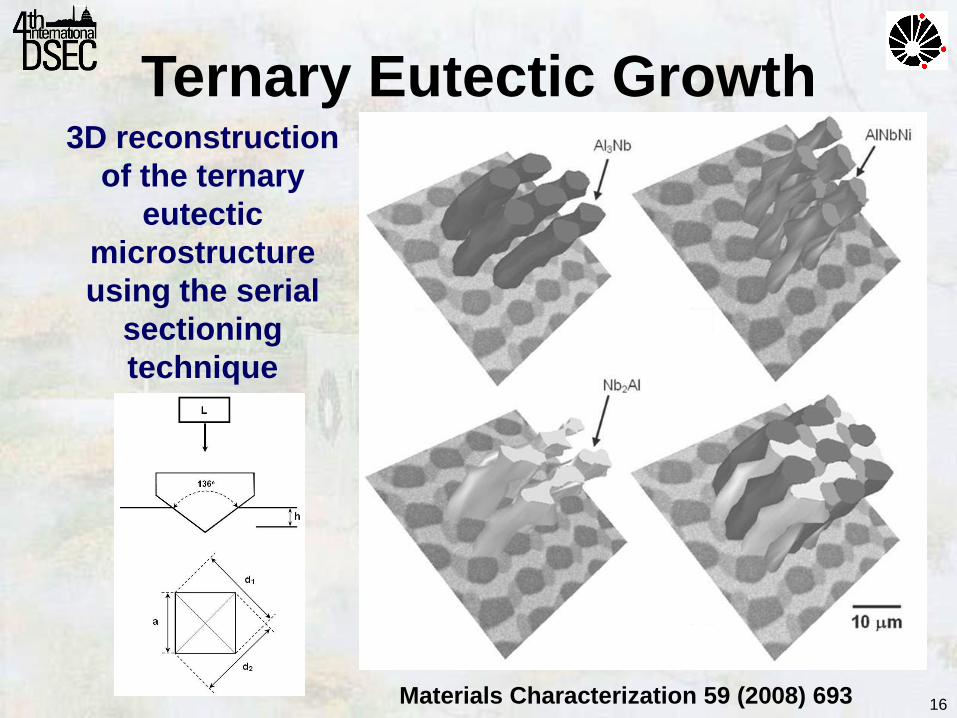
Ternary Eutectic Growth
Materials Characterization 59 (2008) 693
3D reconstruction
of the ternary
eutectic
microstructure
using the serial
sectioning
technique
17
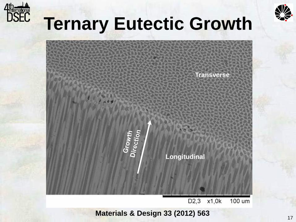
Ternary Eutectic Growth
Materials & Design 33 (2012) 563
Longitudinal
Transverse

18
1700 C o
1500 C o
1300 C o
1100 C o
Quartz Liner
Coil
Susceptor
Graphite
Ingot
Alumina
Crucible
• D.S. of eutectics was carried out by using a vertical Bridgman furnace, in Al2O3 crucibles (0.8 ID x 1.0 cm OD and 6.0 cm long)
• Ti alloys can not be processed in Al2O3 crucibles
Directional Solidification
19
• Mechanical performance of Ti can be
considerably enhanced by combining it and
Fe, causing an eutectic transformation:
Ti: ductile BCC phase
TiFe: high strength phase • Directional solidification was carried out in a
setup that employs a water-cooled copper
crucible combined with a voltaic electric arc
moving through the sample.
Ti-Fe System
L↔ Ti–TiFe 1095oC/Ti-32.5Fe wt%
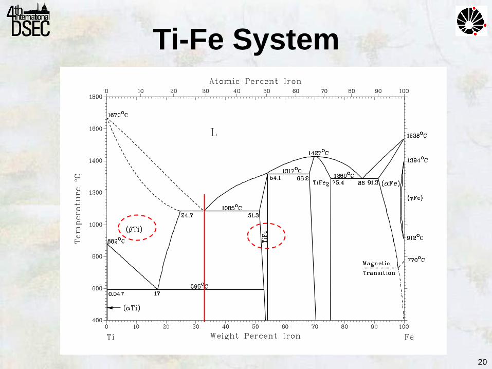
20
A ssessed T i - F e p h ase d iag r am .Ti-Fe System

• Arc furnace with non-consumable W electrode and water cooled copper hearth under Ar atmosphere.
Crucible
Electrode
Sample Preparation
21
Nominal (at.%)
Ti-32.5 Fe

Directional Solidification
Tungsten
Electrode
Liquid
Pool
Water
Cooled
Crucible
Sample
Spindle
• Arc furnace with a nonconsumable W electrode that moves longitudinally along the ingot at different rates
22

• Three solidification rates chosen:
V=10, 30 and 60 mm/h.
Directional Solidification
23

24
• Chemical composition
• X-ray fluorescence spectrometry - Rigaku RIX 3100
• Oxygen and nitrogen - LECO TC-400 analyzer
• Phase transformations
• Differential thermal analysis - Netzsch STA 409
• Microstructure characterization
• Scanning electron microscopy - Zeiss EVO 15
• Transmission electron microscopy - JEOL JEM 2100
• X-ray diffraction - PANalytical X’Pert
• Mechanical characterization
• Vickers Hardness test – Buehler 2100
• Nano-indentation – NHT – CSM Instruments
• Compressive tests – EMIC DL2000
Sample Characterization

25
• Chemical composition:
• X-ray fluorescence spectrometry - Rigaku RIX 3100
• Oxygen and nitrogen - LECO TC-400 analyzer
very low interstitial
contamination
Chemical Composition
Nominal (at.%) Measured (at.%)
Ti-32.5 Fe Ti-32.8 Fe
Ti O (wt.%) N (wt.%)
Balance 0.0855 0.014725
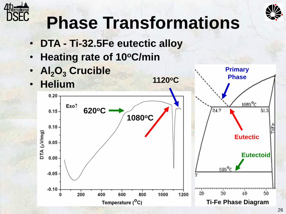
• DTA - Ti-32.5Fe eutectic alloy
• Heating rate of 10oC/min
• Al2O3 Crucible
• Helium
620oC
1080oC
1120oC
Ti-Fe Phase Diagram
Eutectic
Eutectoid
Primary
Phase
26
Phase Transformations

• SEM micrographs of the Ti–Fe eutectic alloy in the as-cast condition
Eutectic Microstructure
phase
(dark gray)
TiFe - Intermetallic Phase
(light gray)
27
As-Cast Condition

28
30 40 50 60 70 80 90
aFeTi
= 0.2996 nm
a= 0.3203 nm
(22
0)
(21
1) F
eT
i
(21
1)
(20
0) F
eT
i
(20
0)
(11
0) F
eT
i
Inte
ns
ity
(a
.u.)
2 (Degrees)
(11
0)
As-cast
aFeTi
= 0.2986 nm
D.S.
a= 0.3182 nm
XRD Patterns
• XRD patterns of Ti–Fe eutectic alloys in as-cast and directionally solidified (DS) conditions
aDS<aAs-cast

• TEM micrographs in bright field mode and SADP
[113]TiFe // [113]
29
TEM Analysis
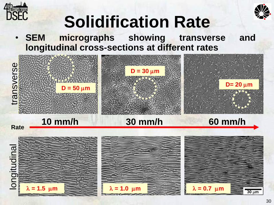
• SEM micrographs showing transverse and longitudinal cross-sections at different rates
transvers
e
lon
gitu
din
al
10 mm/h 30 mm/h 60 mm/h
D = 50 m
D = 30 m
D= 20 m
= 1.5 m = 1.0 m = 0.7 m
Rate
30
Solidification Rate

• Relationship between the average interspace and the solidification rate of d.s. Ti-Fe eutectic alloy
10 mm/h
30 mm/h
60mm/h
2.v=22.3x10⁻¹⁵ m3h-1
31
Solidification Rate

• Evolution of hardness with interphase spacing versus Vickers microhardness (HVmicro) and nanohardness (HVnano).
EE=110 to 177 GPa
ETiFe = 137 GPa
32
Mechanical Tests
Nano-indentation:
Three-sided Berkovich
diamond indenter and
applying a maximum
load of 500 Mn:
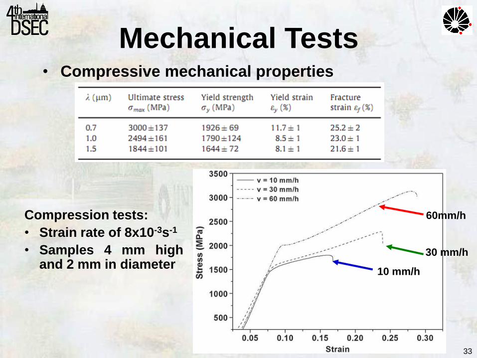
• Compressive mechanical properties
33
Compression tests:
• Strain rate of 8x10⁻³s-1
• Samples 4 mm high and 2 mm in diameter
Mechanical Tests
10 mm/h
30 mm/h
60mm/h

34
Conclusions New experimental setup was applied to D.S. of Ti-Fe eutectic:
• No oxygen contamination
• No evidence of oxygen rich phase
• Well aligned eutectic microstructure
• Eutectic transformation at 1080oC
• TEM/SADP
→ orientation relationship: (113)║(113)TiFe
• 2v=22.3 x 10⁻¹⁵ m3/h
• EE varies from 110 to 177 GPa
• UTS varies from 1844 to 3000 MPa
• Ductility varies from 21.5 to 25.2 %

35
Acknowledgments
• The State of São Paulo Research Foundation
• The Brazilian National Council for Scientific and Technological Development
for financial support

36
2014 World Cup Olympic Games Rio 2016
Visit Brazil