Microstructural Characterization of Custom Age 625 Plus Alloy
10
MICROSTRUCTURAL CHARACTERIZATION OF CUSTOM AGE 625 PLUS@ ALLOY G. F. Vander Voort, J. W. Bowman and R. B. Frank Carpenter Technology Corp. P.O. Box 14662 Reading, Pennsylvania 19612 Abstract Metallographic procedures and microstructural characterization results for Carpenter’s Custom Age 625 PLUS@ alloy, an age-hardenable, highly corrosion resistant Ni-base alloy, are presented. Characterization was performed by light and electron microscopy techniques as a function of solution annealing and aging temperatures and times. The extremely high corrosion resistance of the alloy makes good etch delineation difficult to obtain. Gamma double prime is the main strengthening phase and it is liner in size than in alloy 718. Dark field TEM imaging is required to observe and identify gamma double prime. Observation of coarse gamma double prime is possible with a field emission scanning electron microscope. Introduction The need for suitable alloys for service in deep sour-gas wells has promoted the development of highly corrosion resistant, age-hardenable alloys such as Carpenter’s Custom Age 625 PLUS alloy (l-5). Other age hardenable nickel-based alloys, such as alloys 718 and X-750, have inadequate corrosion resistance for the most severe sour-gas environments containing chlorides and sulfides under high pressures and at temperatures up to about 230°C. Non-heat treatable nickel-based alloys, such as alloys 625 and C-276, have adequate corrosion resistance but require warm working or cold working to increase their strength, which is not always feasible, especially for larger sizes. Custom Age 625 PLUS alloy combines the excellent corrosion resistance of alloy 625 with strengthening by age hardening, similar to alloy 718. This paper presents information concerning metallographic practices and microstructural characteristics of the alloy. Experimental Procedures The nominal composition of Custom Age 625 PLUS alloy is given in Table 1. Material was examined in the following conditions: in the as-rolled condition; after the standard solution anneal and double age treatment (1900°F [1038”C] - 2 h, air cool, age at 1350°F [732”C] for 8 h, furnace cool to 1150°F [621”C], hold 8 h, air cool); after this treatment plus high temperature exposure (500 h at 1200°F [649”C]); after a solution annealing and ovcraging treatment (1900°F for 2 h, air cool, age at 1450°F [788”C] for 8 h, furnace cool to 1200”F, hold 8 h, air cool); and, after single temperature aging treatments. Specimens for light microscopy are prepared Table 1. Nominal Composition of Custom Age 625 PLUS Alloy (Wt.%) C Cr MO Ni Nb Ti Al Fe 0.01 21 8 61 3.4 1.3 0.2 5 Supcralloys 718, 625,706 and Various Derivatives Edited by EA. Loria The Minerals, Metals&Materials Soaety, 1994 489
Transcript of Microstructural Characterization of Custom Age 625 Plus Alloy
MICROSTRUCTURAL CHARACTERIZATION OF
CUSTOM AGE 625 PLUS@ ALLOY
G. F. Vander Voort, J. W. Bowman and R. B. Frank
Carpenter Technology Corp. P.O. Box 14662
Reading, Pennsylvania 19612
Abstract
Metallographic procedures and microstructural characterization results for Carpenter’s Custom Age 625 PLUS@ alloy, an age-hardenable, highly corrosion resistant Ni-base alloy, are presented. Characterization was performed by light and electron microscopy techniques as a function of solution annealing and aging temperatures and times. The extremely high corrosion resistance of the alloy makes good etch delineation difficult to obtain. Gamma double prime is the main strengthening phase and it is liner in size than in alloy 718. Dark field TEM imaging is required to observe and identify gamma double prime. Observation of coarse gamma double prime is possible with a field emission scanning electron microscope.
Introduction
The need for suitable alloys for service in deep sour-gas wells has promoted the development of highly corrosion resistant, age-hardenable alloys such as Carpenter’s Custom Age 625 PLUS alloy (l-5). Other age hardenable nickel-based alloys, such as alloys 718 and X-750, have inadequate corrosion resistance for the most severe sour-gas environments containing chlorides and sulfides under high pressures and at temperatures up to about 230°C. Non-heat treatable nickel-based alloys, such as alloys 625 and C-276, have adequate corrosion resistance but require warm working or cold working to increase their strength, which is not always feasible, especially for larger sizes. Custom Age 625 PLUS alloy combines the excellent corrosion resistance of alloy 625 with strengthening by age hardening, similar to alloy 718. This paper presents information concerning metallographic practices and microstructural characteristics of the alloy.
Experimental Procedures
The nominal composition of Custom Age 625 PLUS alloy is given in Table 1. Material was examined in the following conditions: in the as-rolled condition; after the standard solution anneal and double age treatment (1900°F [1038”C] - 2 h, air cool, age at 1350°F [732”C] for 8 h, furnace cool to 1150°F [621”C], hold 8 h, air cool); after this treatment plus high temperature exposure (500 h at 1200°F [649”C]); after a solution annealing and ovcraging treatment (1900°F for 2 h, air cool, age at 1450°F [788”C] for 8 h, furnace cool to 1200”F, hold 8 h, air cool); and, after single temperature aging treatments. Specimens for light microscopy are prepared
Table 1. Nominal Composition of Custom Age 625 PLUS Alloy (Wt.%) _~ I
C Cr MO Ni Nb Ti Al Fe
0.01 21 8 61 3.4 1.3 0.2 5
Supcralloys 718, 625,706 and Various Derivatives Edited by EA. Loria
The Minerals, Metals&Materials Soaety, 1994
489
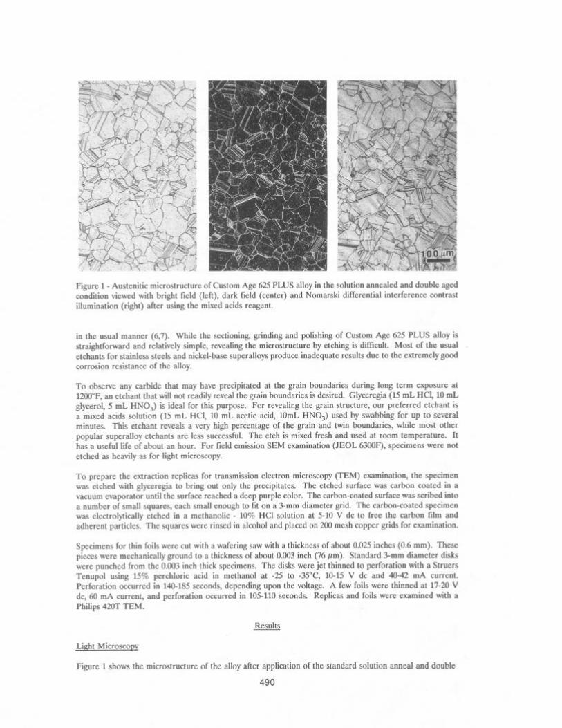
Figure 1 - Austenitic microstructure of Custom Age 625 PLUS alloy in the solution annealed and double aged condition viewed with bright field (left), dark field (center) and Nomarski differential interference contrast illumination (right) after using the mixed acids reagent.
in the usual manner (6,7). While the sectioning, grinding and polishing of Custom Age 625 PLUS alloy is straightforward and relatively simple, revealing the microstructure by etching is difficult. Most of the usual etchants for stainless steels and nickel-base superalloys produce inadequate results due to the extremely good corrosion resistance of the alloy.
To observe any carbide that may have precipitated at the grain boundaries during long term exposure at 12OO”F, an etchant that will not readily reveal the grain boundaries is desired. Glyceregia (15 mL HCI, 10 mL glycerol, 5 mL HNO,) is ideal for this purpose. For revealing the grain structure, our preferred etchant is a mixed acids solution (15 mL HCl, 10 mL acetic acid, 1OmL HNO,) used by swabbing for up to several minutes. This etchant reveals a very high percentage of the grain and twin boundaries, while most other popular superalloy etchants are less successful. The etch is mixed fresh and used at room temperature. It has a useful life of about an hour. For field emission SEM examination (JEOL 63OOF), specimens were not etched as heavily as for light microscopy.
To prepare the extraction replicas for transmission electron microscopy (TEM) examination, the specimen was etched with glyceregia to bring out only the precipitates. The etched surface was carbon coated in a vacuum evaporator until the surface reached a deep purple color. The carbon-coated surface was scribed into a number of small squares, each small enough to tit on a 3-mm diameter grid. The carbon-coated specimen was electrolytically etched in a methanolic - 10% HCl solution at 5-10 V dc to free the carbon film and adherent particles. The squares were rinsed in alcohol and placed on 200 mesh copper grids for examination.
Specimens for thin foils were cut with a wafering saw with a thickness of about 0.025 inches (0.6 mm). These pieces were mechanically ground to a thickness of about 0.003 inch (76 pm). Standard 3-mm diameter disks were punched from the 0.003 inch thick specimens. The disks were jet thinned to perforation with a Struers Tenupol using 15% perchloric acid in methanol at -25 to -35”C, lo-15 V dc and 40-42 mA current. Perforation occurred in 140-185 seconds, depending upon the voltage. A few foils were thinned at 17-20 V dc, 60 mA current, and perforation occurred in 105-110 seconds. Replicas and foils were examined with a Philips 420T TEM.
Results
Light Microscopy
Figure 1 shows the microstructure of the alloy after application of the standard solution anneal and double
490
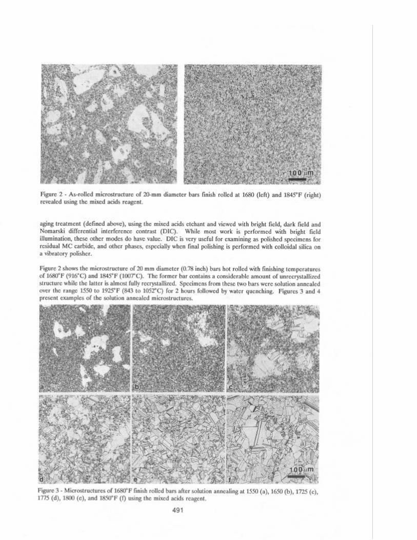
Figure 2 - As-rolled microstructure of 20-mm diameter bars finish rolled at 1680 (left) and 1845°F (right) revealed using the mixed acids reagent.
aging treatment (defined above), using the mixed acids etchant and viewed with bright field, dark field and Nomarski differential interference contrast (DIC). While most work is performed with bright field illumination, these other modes do have value. DIC is very useful for examining as polished specimens for residual MC carbide, and other phases, especially when final polishing is performed with colloidal silica on a vibratory polisher.
Figure 2 shows the microstructure of 20 mm diameter (0.78 inch) bars hot rolled with finishing temperatures of 1680°F (916°C) and 1845°F (1007°C). The former bar contains a considerable amount of unrecrystallized structure while the latter is almost fully recrystallized. Specimens from these two bars were solution annealed over the range 1550 to 1925°F (843 to 1052°C) for 2 hours followed by water quenching. Figures 3 and 4 present examples of the solution annealed microstructures.
Figure 3 - Microstructures of 1680°F finish rolled bars after solution annealing at 1550 (a), 1650 (b), 1725 (c), 1775 (d), 1800 (e), and 1850°F (f) using the mixed acids reagent.
491
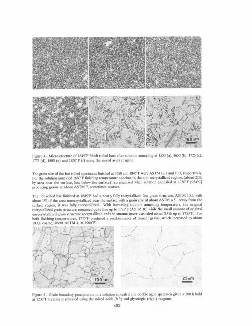
Figure 4 - Microstructure of 1845°F finish rolled bars after solution annealing at 1550 (a), 1650 (b), 1725 (c), 1775 (d), 1800 (e) and 1850°F (f) using the mixed acids reagent.
The grain size of the hot rolled specimens finished at 1680 and 1845°F were ASTM 12.1 and 10.5, respectively. For the solution annealed 1680°F finishing temperature specimens, the non-recrystallized regions (about 22% by area near the surface, less below the surface) recrystallized when solution annealed at 1750°F [954”C] producing grains at about ASTM 7, sometimes coarser.
The hot rolled bar finished at 1845°F had a nearly fully recrystallized tine gram structure, ASTM 10.5, with about 1% of the area unrecrystallized near the surface with a grain size of about ASTM 4.5. Away from the surface region, it was fully recrystallized. With increasing solution annealing temperature, the original recrystallized grain structure remained quite fine up to 1775°F (ASTM 10) while the small amount of original unrecrystallized grain structure recrystallized and the amount never exceeded about 3.3% up to 1750°F. For both finishing temperatures, 1775°F produced a predominance of coarser grains, which increased to about 100% coarse, about ASTM 4, at 1900°F.
,, “. , , . . ..,.... , / I /’
.i -..-- /.
/ >I /A---‘,
_ I % ,\; .‘/’ \
‘< / -- . ._ ’
c ‘.!:“’
,.H+-- ‘l .,-\-_ ?
’ ___ km. . . ,’ ’ 7”‘ 1 -~‘L$~- ,.i.
i -
i
Figure 5 - Grain boundary precipitation in a solution annealed and double aged specimen given a 500 h hold at 1200°F treatment revealed using the mixed acids (left) and glyceregia (right) reagents.
492
>
-c ’
0
741 nm
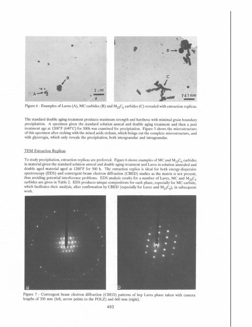
Figure 6 - Examples of Laves (A), MC carbides (B) and M,,C, carbides (C) revealed with extraction replicas.
The standard double aging treatment produces maximum strength and hardness with minimal grain boundary precipitation. A specimen given the standard solution anneal and double aging treatment and then a post treatment age at 1200°F (649°C) for 5OOh was examined for precipitation. Figure 5 shows the microstructure of this specimen after etching with the mixed acids etchant, which brings out the complete microstructure, and with glyceregia, which only reveals the precipitation, both inter-granular and intragranular.
TEM Extraction Replicas
To study precipitation, extraction replicas are preferred. Figure 6 shows examples of MC and M,,C, carbides in material given the standard solution anneal and double aging treatment and Laves in solution annealed and double aged material aged at 1200°F for 500 h. The extraction replica is ideal for both energy-dispersive spectroscopy (EDS) and convergent-beam electron diffraction (CBED) studies as the matrix is not present, thus avoiding potential interference problems. EDS analysis results for a number of Laves, MC and M,,C, carbides are given in Table 2. EDS produces unique compositions for each phase, especially for MC carbide, which facilitates their analysis, after confirmation by CBED (especially for Laves and M2&), in subsequent work.
Figure 7 - Convergent beam electron diffraction (CBED) patterns of hcp Laves phase taken with camera lengths of 350 mm (left, arrow points to the FOLZ) and 660 mm (right).
493
t
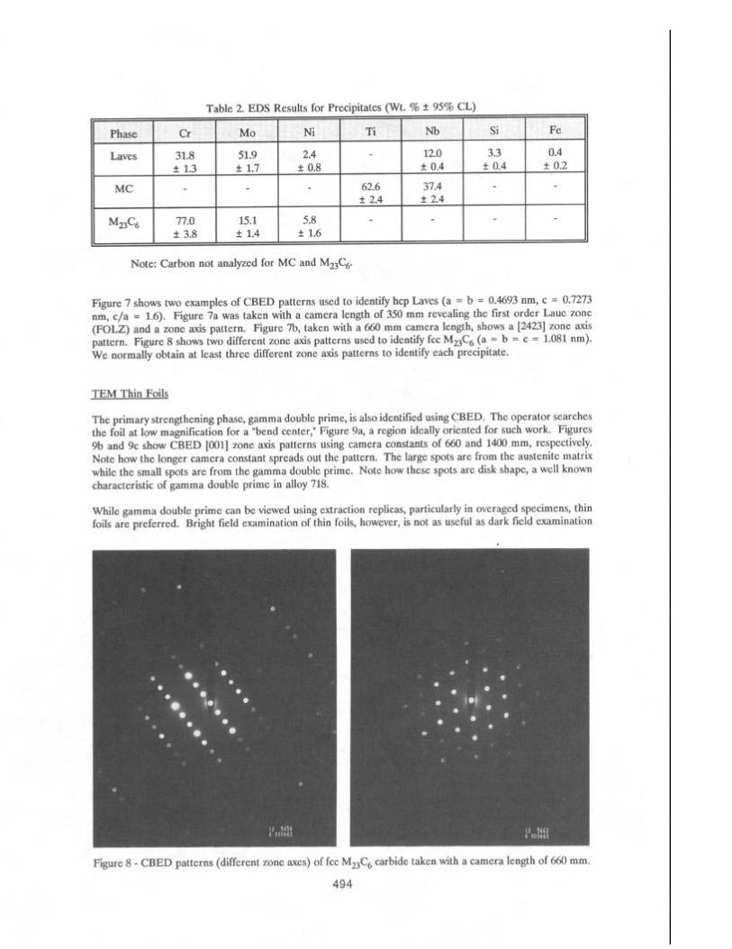
Table 2. EDS Results for prerinitnt~s (Wt. % + 95% CL) .1--r -_---I \ -. I - - --‘- I
Phase Laves
MC
M23C6
Cr 31.8 +- 1.3
77.0 + 3.8
MO Ni Ti Nb Si Fe
51.9 2.4 12.0 3.3 0.4 2 1.7 f 0.8 * 0.4 * 0.4 + 0.2
62.6 37.4 f 2.4 ?r 2.4
15.1 5.8 f 1.4 ?r 1.6
Note: Carbon not analyzed for MC and M23C,5.
Figure 7 shows two examples of CBED patterns used to identify hcp Laves (a = b = 0.4693 nm, c = 0.7273 nm, c/a = 1.6). Figure 7a was taken with a camera length of 350 mm revealing the tirst order Laue zone (FOLZ) and a zone axis pattern. Figure 7b, taken with a 660 mm camera length, shows a [2423] zone axis pattern. Figure 8 shows two different zone axis patterns used to identify fee MUC6 (a = b = c = 1.081 nm). We normally obtain at least three different zone axis patterns to identify each precipitate.
TEM Thin Foils
The primary strengthening phase, gamma double prime, is also identified using CBED. The operator searches the foil at low magnification for a “bend center,” Figure 9a, a region ideally oriented for such work. Figures 9b and 9c show CBED [OOl] zone axis patterns using camera constants of 660 and 1400 mm, respectively. Note how the longer camera constant spreads out the pattern. The large spots are from the austenite matrix while the small spots are from the gamma double prime. Note how these spots are disk shape, a well known characteristic of gamma double prime in alloy 718.
While gamma double prime can be viewed using extraction replicas, particularly in overaged specimens, thin foils are preferred. Bright field examination of thin foils, however, is not as useful as dark field examination
Figure 8 - CBED patterns (different zone axes) of fee M23C6 carbide taken with a camera length of 660 mm.
494
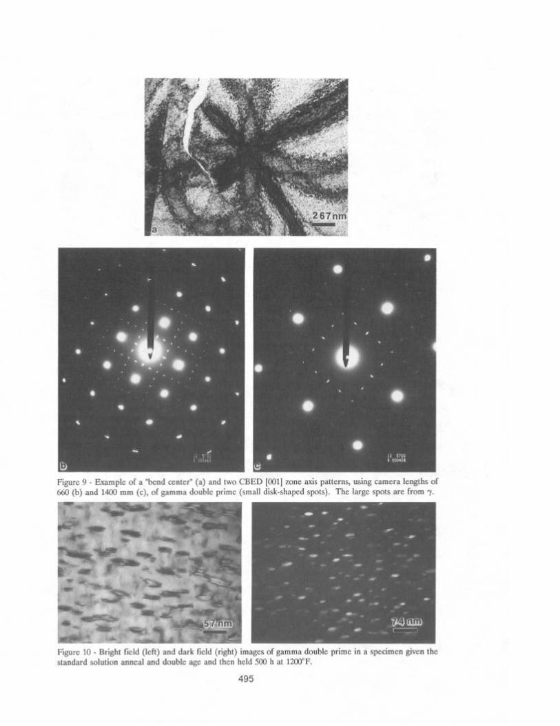
Figure 9 - Example of a “bend center” (a) and two CBED [OOl] _ lone axis patterns, using camera lengths of 660 (b) and 1400 mm (c), of gamma double prime (small disk-shaped spots). The large spots are from 7.
Figure 10 - Bright field (left) and dark lield (right) images of gamma double prime in a specimen given the standard solution anneal and double age and then held 500 h at 1200°F.
495
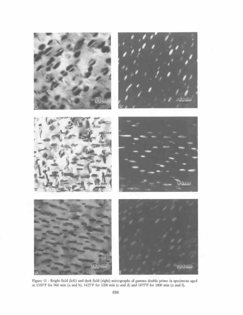
Figure 11 - Bright field (left) and dark field (right) micrographs of gamma double prime in specimens aged at 1350°F for 960 min (a and b), 1425°F for 1200 min (c and d) and 1475°F for 1800 min (e and f).
496
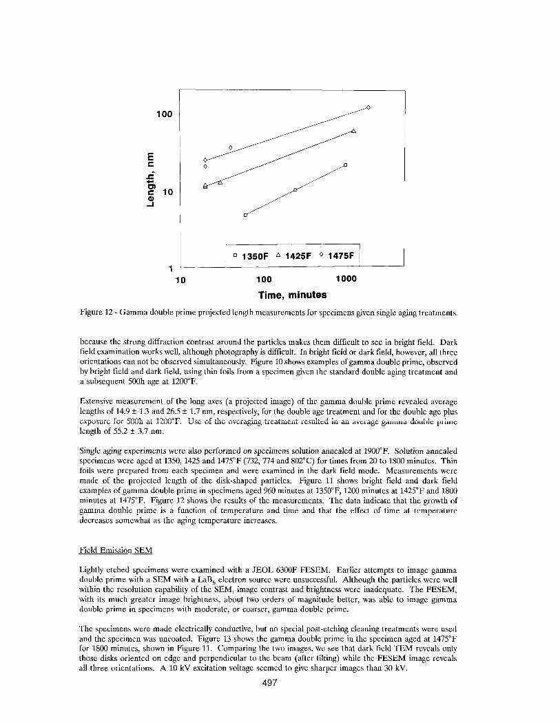
q 135OF A 1425F o 1475F
1 10 100 1600
Time, minutes
Figure 12 - Gamma double prime projected length measurements for specimens given single aging treatments.
because the strong diffraction contrast around the particles makes them difficult to see in bright field. Dark field examination works well, although photography is difficult. In bright field or dark field, however, all three orientations can not be observed simultaneously. Figure 10 shows examples of gamma double prime, observed by bright field and dark field, using thin foils from a specimen given the standard double aging treatment and a subsequent 500h age at 1200°F.
Extensive measurement of the long axes (a projected image) of the gamma double prime revealed average lengths of 14.9 t 1.3 and 26.5 + 1.7 nm, respectively, for the double age treatment and for the double age plus exposure for 500h at 1200°F. Use of the overaging treatment resulted in an average gamma double prime length of 55.2 + 3.7 nm.
Single aging experiments were also performed on specimens solution annealed at 1900°F. Solution annealed specimens were aged at 1350, 1425 and 1475°F (732,774 and 802’C) for times from 20 to 1800 minutes. Thin foils were prepared from each specimen and were examined in the dark field mode. Measurements were made of the projected length of the disk-shaped particles. Figure 11 shows bright field and dark field examples of gamma double prime in specimens aged 960 minutes at 1350”F, 1200 minutes at 1425°F and 1800 minutes at 1475°F. Figure 12 shows the results of the measurements. The data indicate that the growth of gamma double prime is a function of temperature and time and that the effect of time at temperature decreases somewhat as the aging temperature increases.
Field Emission SEM
Lightly etched specimens were examined with a JEOL 6300F FESEM. Earlier attempts to image gamma double prime with a SEM with a LaB6 electron source were unsuccessful. Although the particles were well within the resolution capability of the SEM, image contrast and brightness were inadequate. The FESEM, with its much greater image brightness, about two orders of magnitude better, was able to image gamma double prime in specimens with moderate, or coarser, gamma double prime.
The specimens were made electrically conductive, but no special post-etching cleaning treatments were used and the specimen was uncoated. Figure 13 shows the gamma double prime in the specimen aged at 1475°F for 1800 minutes, shown in Figure 11. Comparing the two images, we see that dark field TEM reveals only those disks oriented on edge and perpendicular to the beam (after tilting) while the FESEM image reveals all three orientations. A 10 kV excitation voltage seemed to give sharper images than 30 kV.
497
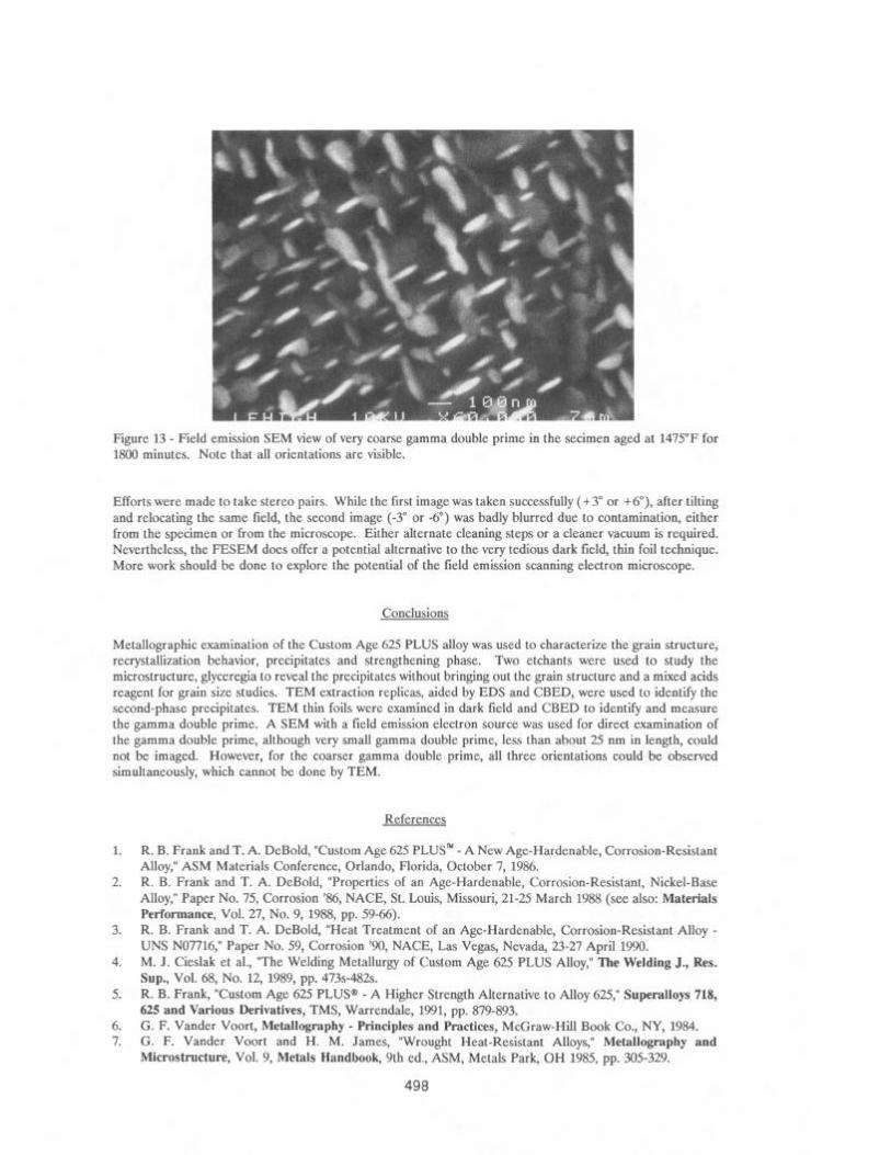
Figure 13 - Field emission SEM view of very coarse gamma double prime in the secimen aged at 1475°F for 1800 minutes. Note that all orientations are visible.
Efforts were made to take stereo pairs. While the first image was taken successfully (+3” or +6”), after tilting and relocating the same field, the second image (-3” or -6”) was badly blurred due to contamination, either from the specimen or from the microscope. Either alternate cleaning steps or a cleaner vacuum is required. Nevertheless, the FESEM does offer a potential alternative to the very tedious dark field, thin foil technique. More work should be done to explore the potential of the field emission scanning electron microscope.
Metallographic examination of the Custom Age 625 PLUS alloy was used to characterize the grain structure, recrystallization behavior, precipitates and strengthening phase. Two etchants were used to study the microstructure, glyceregia to reveal the precipitates without bringing out the grain structure and a mixed acids reagent for grain size studies. TEM extraction replicas, aided by EDS and CBED, were used to identify the second-phase precipitates. TEM thin foils were examined in dark field and CBED to identify and measure the gamma double prime. A SEM with a field emission electron source was used for direct examination of the gamma double prime, although very small gamma double prime, less than about 25 nm in length, could not be imaged. However, for the coarser gamma double prime, all three orientations could be observed simultaneously, which cannot be done by TEM.
1.
2.
3.
4.
5.
6. 7.
References
R. B. Frank and T. A. DeBold, “Custom Age 625 PLUS” - A New Age-Hardenable, Corrosion-Resistant Alloy,” ASM Materials Conference, Orlando, Florida, October 7, 1986. R. B. Frank and T. A. DeBold, “Properties of an Age-Hardenable, Corrosion-Resistant, Nickel-Base Alloy,” Paper No. 75, Corrosion ‘86, NACE, St. Louis, Missouri, 21-25 March 1988 (see also: Materials Performance, Vol. 27, No. 9, 1988, pp. 59-66). R. B. Frank and T. A. DeBold, “Heat Treatment of an Age-Hardenable, Corrosion-Resistant Alloy - UNS NO7716,” Paper No. 59, Corrosion ‘90, NACE, Las Vegas, Nevada, 23-27 April 1990. M. J. Cieslak et al., “The Welding Metallurgy of Custom Age 625 PLUS Alloy,” The Welding J., Res. Sup., Vol. 68, No. 12, 1989, pp. 473~482s. R. B. Frank, “Custom Age 625 PLUS@ - A Higher Strength Alternative to Alloy 625,” Superalloys 718, 625 and Various Derivatives, TMS, Warrendale, 1991, pp. 879-893. G. F. Vander Voort, Metallography - Principles and Practices, McGraw-Hill Book Co., NY, 1984. G. F. Vander Voort and H. M. James, “Wrought Heat-Resistant Alloys,” Metallography and Microstructure, Vol. 9, Metals Handbook, 9th ed., ASM, Metals Park, OH 1985, pp. 305-329.
498