Microservices Migration Patterns - Armin Balalaiearminb.me/microservices/report.pdf · factors that...
21
Microservices Migration Patterns Armin Balalaie Department of Computer Engineering, Sharif University of Technology, Tehran, Iran The corresponding author, [email protected] Abbas Heydarnoori Department of Computer Engineering, Sharif University of Technology, Tehran, Iran [email protected] Pooyan Jamshidi Department of Computing, Imperial College London, London, UK [email protected] Technical Report Automated Software Engineering Group (http://ase.ce.sharif.edu) Department of Computer Engineering Sharif University of Technology October 2015 Citation A. Balalaie, A. Heydarnoori, P. Jamshidi, Microservices Migration Patterns, Technical Report No. 1, TR- SUT-CE-ASE-2015-01, Automated Software Engineering Group, Sharif University of Technology, October, 2015 [Available Online at http://ase.ce.sharif.edu/pubs/techreports/TR-SUT-CE-ASE-2015-01-Microservices. pdf]
Transcript of Microservices Migration Patterns - Armin Balalaiearminb.me/microservices/report.pdf · factors that...

Microservices Migration Patterns
Armin BalalaieDepartment of Computer Engineering, Sharif University of Technology, Tehran, IranThe corresponding author, [email protected]
Abbas HeydarnooriDepartment of Computer Engineering, Sharif University of Technology, Tehran, [email protected]
Pooyan JamshidiDepartment of Computing, Imperial College London, London, [email protected]
Technical ReportAutomated Software Engineering Group (http://ase.ce.sharif.edu)Department of Computer EngineeringSharif University of TechnologyOctober 2015
CitationA. Balalaie, A. Heydarnoori, P. Jamshidi, Microservices Migration Patterns, Technical Report No. 1, TR-SUT-CE-ASE-2015-01, Automated Software Engineering Group, Sharif University of Technology, October,2015 [Available Online at http://ase.ce.sharif.edu/pubs/techreports/TR-SUT-CE-ASE-2015-01-Microservices.pdf]
Contents
1 Introduction 1
2 Pattern Meta-model and Specification Template 22.1 Pattern Specification Template . . . . . . . . . . . . . . . . . . . . . . . . . . . . . . . . . . . 3
3 Migration and Re-architecture Patterns 33.1 MP1-Enable the Continuous Integration . . . . . . . . . . . . . . . . . . . . . . . . . . . . . . 33.2 MP2-Recover the Current Architecture . . . . . . . . . . . . . . . . . . . . . . . . . . . . . . . 43.3 MP3-Decompose the Monolith . . . . . . . . . . . . . . . . . . . . . . . . . . . . . . . . . . . 63.4 MP4-Decompose the Monolith Based on Data Ownership . . . . . . . . . . . . . . . . . . . . 73.5 MP5-Change Code Dependency to Service Call . . . . . . . . . . . . . . . . . . . . . . . . . . 83.6 MP6-Introduce Service Discovery . . . . . . . . . . . . . . . . . . . . . . . . . . . . . . . . . . 93.7 MP7-Introduce Service Discovery Client . . . . . . . . . . . . . . . . . . . . . . . . . . . . . . 103.8 MP8-Introduce Internal Load Balancer . . . . . . . . . . . . . . . . . . . . . . . . . . . . . . . 103.9 MP9-Introduce External Load Balancer . . . . . . . . . . . . . . . . . . . . . . . . . . . . . . 113.10 MP10-Introduce Circuit Breaker . . . . . . . . . . . . . . . . . . . . . . . . . . . . . . . . . . 123.11 MP11-Introduce Configuration Server . . . . . . . . . . . . . . . . . . . . . . . . . . . . . . . 133.12 MP12-Introduce Edge Server . . . . . . . . . . . . . . . . . . . . . . . . . . . . . . . . . . . . 143.13 MP13-Containerize the Services . . . . . . . . . . . . . . . . . . . . . . . . . . . . . . . . . . . 153.14 MP14-Deploy into a Cluster and Orchestrate Containers . . . . . . . . . . . . . . . . . . . . . 163.15 MP15-Monitor the System and Provide Feedback . . . . . . . . . . . . . . . . . . . . . . . . . 17
4 Selecting and Composing Migration Patterns 18
5 Adding New Patterns to the Repository 18
1 Introduction
Microservices is a cloud-native architecture through which a software system can be realized as a set ofsmall services. Each of these services are capable of being deployed independently on a different platformand ran in their own process while communicating through lightweight mechanisms like RESTFull APIs. Inthis setting, each service is a business capability which can use various programming languages and datastores [1].Migrating current on-premise software systems to microservices introduces many benefits including, but notlimited to, different management of availability and scalability for different parts of the system, ability toutilize different technologies and avoid technology lock-in, reduced time-to-market, and better comprehensi-bility of the code base [2]. Furthermore, the migrated system can make use of the elasticity and better pricingmodel of the cloud environment, and therefore, providing a better user-experience for its end-users [2]. Al-though microservices presents many benefits, it introduces distribution complexities to the system for whichnew supporting components, e.g., Service Discovery, are needed. The difficulties around the decompositionof a system into small services, and monitoring and managing these services are amongst the other importantfactors that make migrating to microservices a non-trivial and cumbersome task.Migrating to cloud, and in particular migrating through cloud-native architectures, like microservices, is amulti-dimensional problem and a non-trivial task [3]. Hence, in the absence of a well-thought methodology,it can be changed to a trial-and-error endeavor which can not only waste a lot of time, but also lead to awrong solution. Furthermore, regarding the variation of factors like the requirements, the current situation,the skills of team members, etc., in different companies and scenarios, a unique and rigid methodology wouldnot be enough. Thus, instead of a one-fit-all methodology, a Situational Method Engineering (SME) [4]approach is needed.The first step towards the SME approach is to populate a method base or pattern repository with reusableprocess patterns or method chunks which we designate them as migration patterns in this report. It isimportant to note that each of these migration patterns should conform to a predefined meta-model. Tothis end, using our previous experience in SME [5] and defining migration patterns [6], in this report, wegeneralize our experience in migration to microservices [2] and similar practices in the state-of-the-art ofmicroservices as migration patterns. These patterns are merely focused on Migration Planning phase. Weenriched each step in the migration process with the precise definition of the corresponding situation, theproblem to be solved, and the possible challenges of the proposed solution. After that, we transferred themto a pattern template which its parts has one-to-one correspondence with the meta-model elements. Partsof these patterns describes exactly why we need supporting components, e.g., Service Discovery, in ourarchitecture, and what is the requirements for their introduction. Additionally, we provide some solutionsand advices for decomposition of a monolithic system to a set of services, and defining the current and thetarget architectures of the system as a roadmap for migration planning. Still, we provide some clues aboutthe containerization of services and their deployment in a cluster. Keeping the system in a stable state afterapplying a pattern and performing one architectural change at a time were the most important factors indetermining the granularity of patterns.Having a suitable pattern repository, a method engineer can select required patterns using selection guidelinesand construct a bespoke methodology by composing the selected patterns.The rest of this report is organized as follows: In Section 2, we present the meta-model and the patternspecification template conforming to that meta-model which used for pattern’s documentation. Section 3elaborates the devised migration patterns in detail. Section 4 explains migration pattern selection and theprocedure of creating a methodology by composing the selected patterns. Finally, the process of adding newpatterns to the current pattern repository is discussed in Section 5.
1
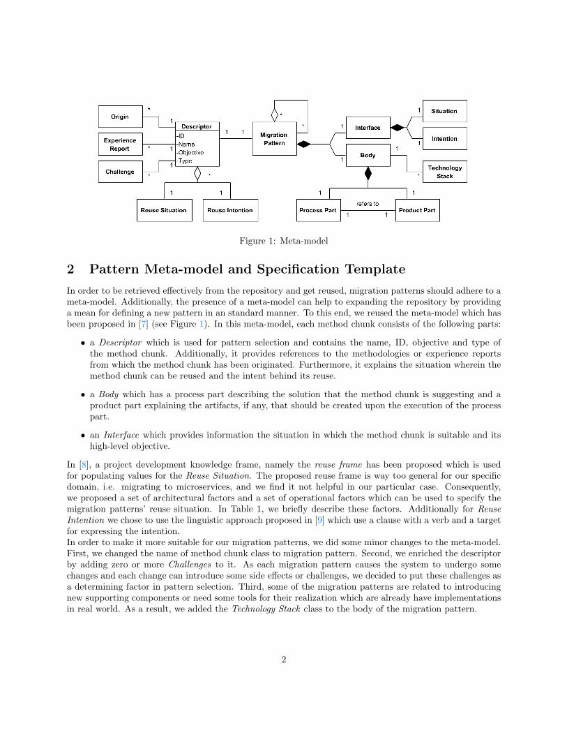
Figure 1: Meta-model
2 Pattern Meta-model and Specification Template
In order to be retrieved effectively from the repository and get reused, migration patterns should adhere to ameta-model. Additionally, the presence of a meta-model can help to expanding the repository by providinga mean for defining a new pattern in an standard manner. To this end, we reused the meta-model which hasbeen proposed in [7] (see Figure 1). In this meta-model, each method chunk consists of the following parts:
• a Descriptor which is used for pattern selection and contains the name, ID, objective and type ofthe method chunk. Additionally, it provides references to the methodologies or experience reportsfrom which the method chunk has been originated. Furthermore, it explains the situation wherein themethod chunk can be reused and the intent behind its reuse.
• a Body which has a process part describing the solution that the method chunk is suggesting and aproduct part explaining the artifacts, if any, that should be created upon the execution of the processpart.
• an Interface which provides information the situation in which the method chunk is suitable and itshigh-level objective.
In [8], a project development knowledge frame, namely the reuse frame has been proposed which is usedfor populating values for the Reuse Situation. The proposed reuse frame is way too general for our specificdomain, i.e. migrating to microservices, and we find it not helpful in our particular case. Consequently,we proposed a set of architectural factors and a set of operational factors which can be used to specify themigration patterns’ reuse situation. In Table 1, we briefly describe these factors. Additionally for ReuseIntention we chose to use the linguistic approach proposed in [9] which use a clause with a verb and a targetfor expressing the intention.In order to make it more suitable for our migration patterns, we did some minor changes to the meta-model.First, we changed the name of method chunk class to migration pattern. Second, we enriched the descriptorby adding zero or more Challenges to it. As each migration pattern causes the system to undergo somechanges and each change can introduce some side effects or challenges, we decided to put these challenges asa determining factor in pattern selection. Third, some of the migration patterns are related to introducingnew supporting components or need some tools for their realization which are already have implementationsin real world. As a result, we added the Technology Stack class to the body of the migration pattern.
2
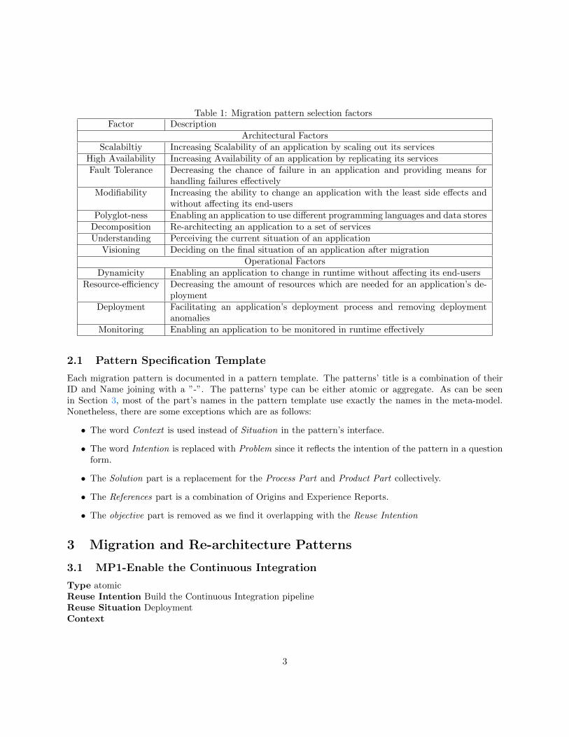
Table 1: Migration pattern selection factorsFactor Description
Architectural FactorsScalabiltiy Increasing Scalability of an application by scaling out its services
High Availability Increasing Availability of an application by replicating its servicesFault Tolerance Decreasing the chance of failure in an application and providing means for
handling failures effectivelyModifiability Increasing the ability to change an application with the least side effects and
without affecting its end-usersPolyglot-ness Enabling an application to use different programming languages and data stores
Decomposition Re-architecting an application to a set of servicesUnderstanding Perceiving the current situation of an application
Visioning Deciding on the final situation of an application after migrationOperational Factors
Dynamicity Enabling an application to change in runtime without affecting its end-usersResource-efficiency Decreasing the amount of resources which are needed for an application’s de-
ploymentDeployment Facilitating an application’s deployment process and removing deployment
anomaliesMonitoring Enabling an application to be monitored in runtime effectively
2.1 Pattern Specification Template
Each migration pattern is documented in a pattern template. The patterns’ title is a combination of theirID and Name joining with a ”-”. The patterns’ type can be either atomic or aggregate. As can be seenin Section 3, most of the part’s names in the pattern template use exactly the names in the meta-model.Nonetheless, there are some exceptions which are as follows:
• The word Context is used instead of Situation in the pattern’s interface.
• The word Intention is replaced with Problem since it reflects the intention of the pattern in a questionform.
• The Solution part is a replacement for the Process Part and Product Part collectively.
• The References part is a combination of Origins and Experience Reports.
• The objective part is removed as we find it overlapping with the Reuse Intention
3 Migration and Re-architecture Patterns
3.1 MP1-Enable the Continuous Integration
Type atomicReuse Intention Build the Continuous Integration pipelineReuse Situation DeploymentContext
3
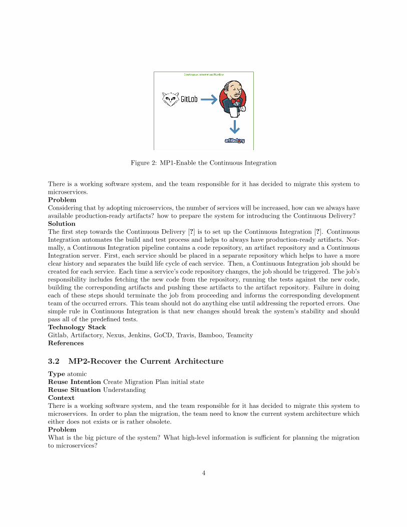
Figure 2: MP1-Enable the Continuous Integration
There is a working software system, and the team responsible for it has decided to migrate this system tomicroservices.ProblemConsidering that by adopting microservices, the number of services will be increased, how can we always haveavailable production-ready artifacts? how to prepare the system for introducing the Continuous Delivery?SolutionThe first step towards the Continuous Delivery [?] is to set up the Continuous Integration [?]. ContinuousIntegration automates the build and test process and helps to always have production-ready artifacts. Nor-mally, a Continuous Integration pipeline contains a code repository, an artifact repository and a ContinuousIntegration server. First, each service should be placed in a separate repository which helps to have a moreclear history and separates the build life cycle of each service. Then, a Continuous Integration job should becreated for each service. Each time a service’s code repository changes, the job should be triggered. The job’sresponsibility includes fetching the new code from the repository, running the tests against the new code,building the corresponding artifacts and pushing these artifacts to the artifact repository. Failure in doingeach of these steps should terminate the job from proceeding and informs the corresponding developmentteam of the occurred errors. This team should not do anything else until addressing the reported errors. Onesimple rule in Continuous Integration is that new changes should break the system’s stability and shouldpass all of the predefined tests.Technology StackGitlab, Artifactory, Nexus, Jenkins, GoCD, Travis, Bamboo, TeamcityReferences
3.2 MP2-Recover the Current Architecture
Type atomicReuse Intention Create Migration Plan initial stateReuse Situation UnderstandingContextThere is a working software system, and the team responsible for it has decided to migrate this system tomicroservices. In order to plan the migration, the team need to know the current system architecture whicheither does not exists or is rather obsolete.ProblemWhat is the big picture of the system? What high-level information is sufficient for planning the migrationto microservices?
4
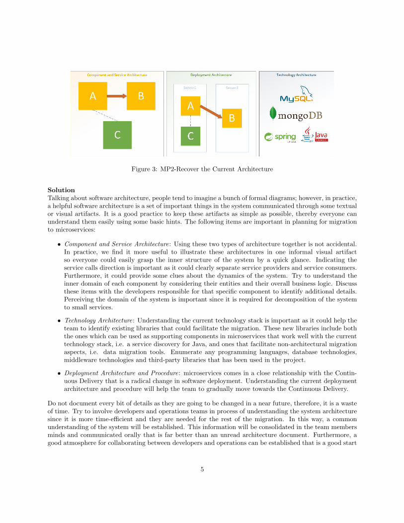
Figure 3: MP2-Recover the Current Architecture
SolutionTalking about software architecture, people tend to imagine a bunch of formal diagrams; however, in practice,a helpful software architecture is a set of important things in the system communicated through some textualor visual artifacts. It is a good practice to keep these artifacts as simple as possible, thereby everyone canunderstand them easily using some basic hints. The following items are important in planning for migrationto microservices:
• Component and Service Architecture: Using these two types of architecture together is not accidental.In practice, we find it more useful to illustrate these architectures in one informal visual artifactso everyone could easily grasp the inner structure of the system by a quick glance. Indicating theservice calls direction is important as it could clearly separate service providers and service consumers.Furthermore, it could provide some clues about the dynamics of the system. Try to understand theinner domain of each component by considering their entities and their overall business logic. Discussthese items with the developers responsible for that specific component to identify additional details.Perceiving the domain of the system is important since it is required for decomposition of the systemto small services.
• Technology Architecture: Understanding the current technology stack is important as it could help theteam to identify existing libraries that could facilitate the migration. These new libraries include boththe ones which can be used as supporting components in microservices that work well with the currenttechnology stack, i.e. a service discovery for Java, and ones that facilitate non-architectural migrationaspects, i.e. data migration tools. Enumerate any programming languages, database technologies,middleware technologies and third-party libraries that has been used in the project.
• Deployment Architecture and Procedure: microservices comes in a close relationship with the Contin-uous Delivery that is a radical change in software deployment. Understanding the current deploymentarchitecture and procedure will help the team to gradually move towards the Continuous Delivery.
Do not document every bit of details as they are going to be changed in a near future, therefore, it is a wasteof time. Try to involve developers and operations teams in process of understanding the system architecturesince it is more time-efficient and they are needed for the rest of the migration. In this way, a commonunderstanding of the system will be established. This information will be consolidated in the team membersminds and communicated orally that is far better than an unread architecture document. Furthermore, agood atmosphere for collaborating between developers and operations can be established that is a good start
5
for a DevOps spirit. Put these artifacts in a place so that everyone in the team could see them. Be open tothe comments since they may reveal some important details about the system.References
3.3 MP3-Decompose the Monolith
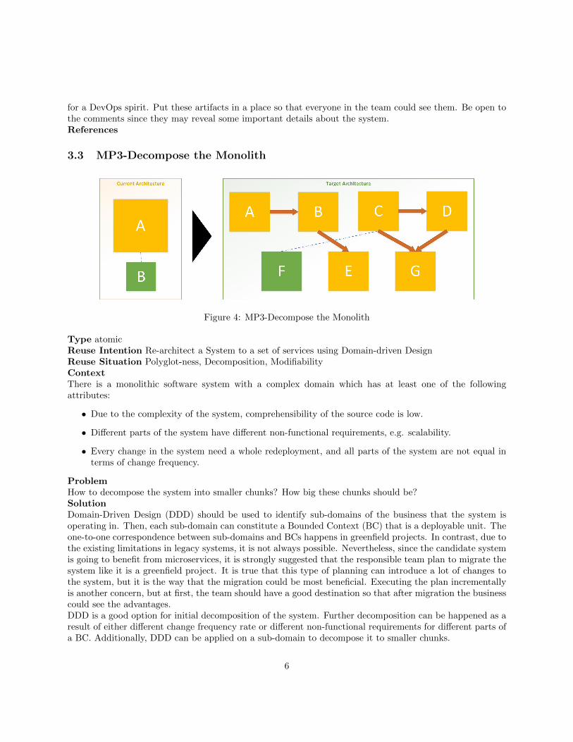
Figure 4: MP3-Decompose the Monolith
Type atomicReuse Intention Re-architect a System to a set of services using Domain-driven DesignReuse Situation Polyglot-ness, Decomposition, ModifiabilityContextThere is a monolithic software system with a complex domain which has at least one of the followingattributes:
• Due to the complexity of the system, comprehensibility of the source code is low.
• Different parts of the system have different non-functional requirements, e.g. scalability.
• Every change in the system need a whole redeployment, and all parts of the system are not equal interms of change frequency.
ProblemHow to decompose the system into smaller chunks? How big these chunks should be?SolutionDomain-Driven Design (DDD) should be used to identify sub-domains of the business that the system isoperating in. Then, each sub-domain can constitute a Bounded Context (BC) that is a deployable unit. Theone-to-one correspondence between sub-domains and BCs happens in greenfield projects. In contrast, due tothe existing limitations in legacy systems, it is not always possible. Nevertheless, since the candidate systemis going to benefit from microservices, it is strongly suggested that the responsible team plan to migrate thesystem like it is a greenfield project. It is true that this type of planning can introduce a lot of changes tothe system, but it is the way that the migration could be most beneficial. Executing the plan incrementallyis another concern, but at first, the team should have a good destination so that after migration the businesscould see the advantages.DDD is a good option for initial decomposition of the system. Further decomposition can be happened as aresult of either different change frequency rate or different non-functional requirements for different parts ofa BC. Additionally, DDD can be applied on a sub-domain to decompose it to smaller chunks.
6
The size of the BCs is nothing that can be recommended or suggested. It totally depends on the systemsrequirements. At the beginning, they can be as large as the corresponding domain. As time goes on,requirements will change, and the previous boundaries or BC sizes may not be appropriate anymore. It isrecommended to start with low number of services, e.g. two or three, and incrementally add more servicesas the system grows and the team understand microservices and the systems requirements better.ChallengesA bad system decomposition can lead to performance penalties due to chatty services or unresolved challengesthat lead the team to the process of migration.References
3.4 MP4-Decompose the Monolith Based on Data Ownership
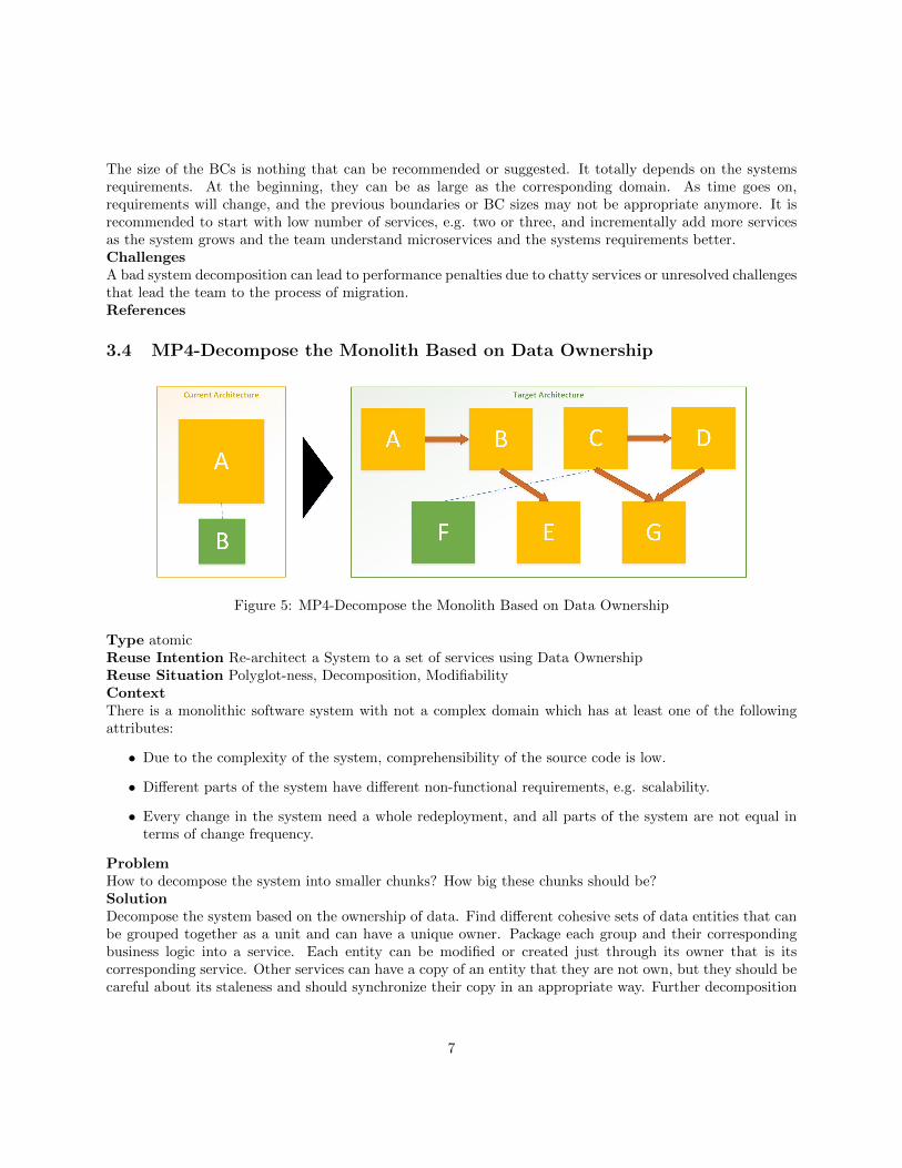
Figure 5: MP4-Decompose the Monolith Based on Data Ownership
Type atomicReuse Intention Re-architect a System to a set of services using Data OwnershipReuse Situation Polyglot-ness, Decomposition, ModifiabilityContextThere is a monolithic software system with not a complex domain which has at least one of the followingattributes:
• Due to the complexity of the system, comprehensibility of the source code is low.
• Different parts of the system have different non-functional requirements, e.g. scalability.
• Every change in the system need a whole redeployment, and all parts of the system are not equal interms of change frequency.
ProblemHow to decompose the system into smaller chunks? How big these chunks should be?SolutionDecompose the system based on the ownership of data. Find different cohesive sets of data entities that canbe grouped together as a unit and can have a unique owner. Package each group and their correspondingbusiness logic into a service. Each entity can be modified or created just through its owner that is itscorresponding service. Other services can have a copy of an entity that they are not own, but they should becareful about its staleness and should synchronize their copy in an appropriate way. Further decomposition
7
can be happened as a result of either different change frequency rate or different non-functional requirementsfor different parts of a service.The size of the services is nothing that can be recommended or suggested. It totally depends on the entitiesexist in the system. For a system with not a complex domain it would not be more than four or five services.ChallengesThis pattern is suitable when the domain of the system is not complex and the data entities can be groupedeasily. In a large domain that has multiple sub-domains, applying this pattern could be confusing andtime-consuming and even can lead to a not appropriate decomposition.References
3.5 MP5-Change Code Dependency to Service Call
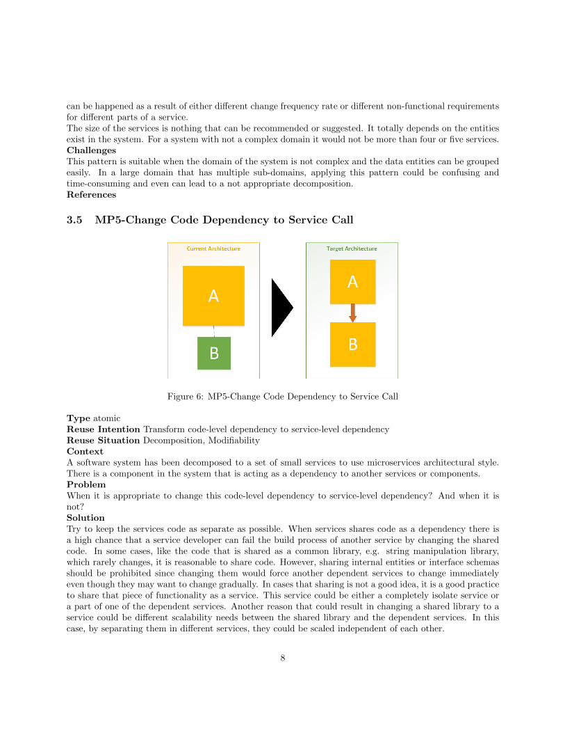
Figure 6: MP5-Change Code Dependency to Service Call
Type atomicReuse Intention Transform code-level dependency to service-level dependencyReuse Situation Decomposition, ModifiabilityContextA software system has been decomposed to a set of small services to use microservices architectural style.There is a component in the system that is acting as a dependency to another services or components.ProblemWhen it is appropriate to change this code-level dependency to service-level dependency? And when it isnot?SolutionTry to keep the services code as separate as possible. When services shares code as a dependency there isa high chance that a service developer can fail the build process of another service by changing the sharedcode. In some cases, like the code that is shared as a common library, e.g. string manipulation library,which rarely changes, it is reasonable to share code. However, sharing internal entities or interface schemasshould be prohibited since changing them would force another dependent services to change immediatelyeven though they may want to change gradually. In cases that sharing is not a good idea, it is a good practiceto share that piece of functionality as a service. This service could be either a completely isolate service ora part of one of the dependent services. Another reason that could result in changing a shared library to aservice could be different scalability needs between the shared library and the dependent services. In thiscase, by separating them in different services, they could be scaled independent of each other.
8
ChallengesSometimes separating libraries from their dependents and using a service call instead of a method call couldintroduce performance issues. Although performance issues can be handled using careful caching mechanisms,it adds another layer of complexity to the dependent service.References
3.6 MP6-Introduce Service Discovery
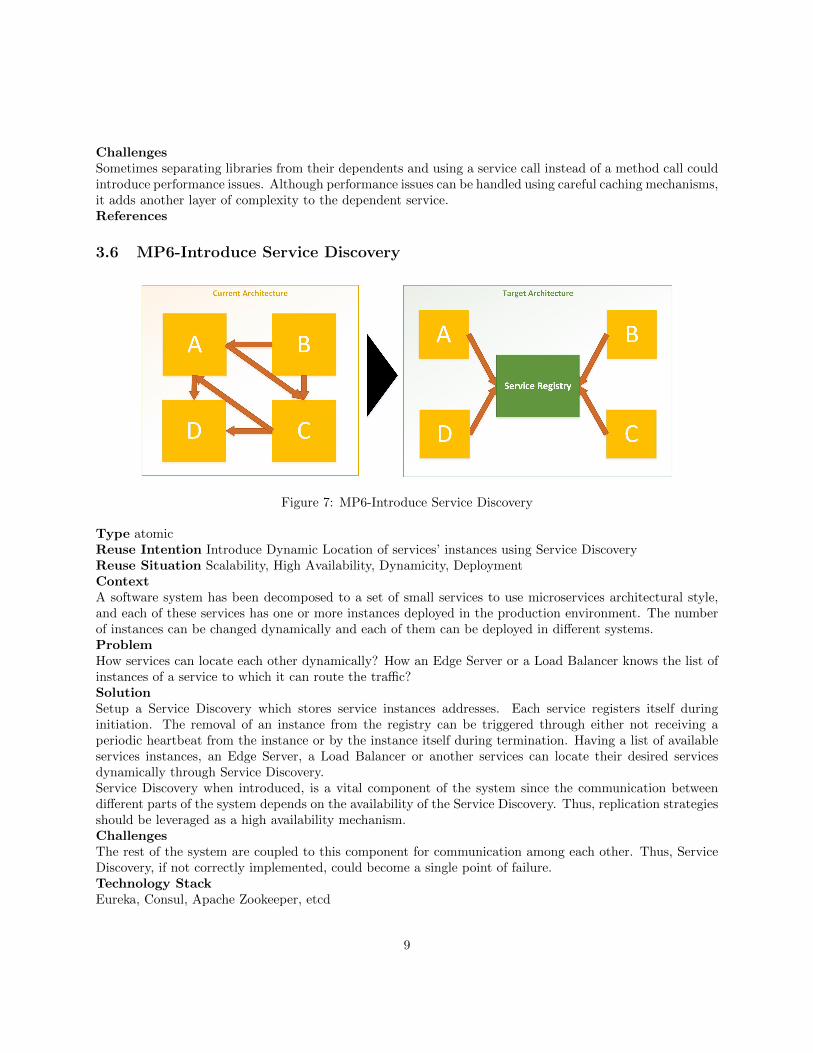
Figure 7: MP6-Introduce Service Discovery
Type atomicReuse Intention Introduce Dynamic Location of services’ instances using Service DiscoveryReuse Situation Scalability, High Availability, Dynamicity, DeploymentContextA software system has been decomposed to a set of small services to use microservices architectural style,and each of these services has one or more instances deployed in the production environment. The numberof instances can be changed dynamically and each of them can be deployed in different systems.ProblemHow services can locate each other dynamically? How an Edge Server or a Load Balancer knows the list ofinstances of a service to which it can route the traffic?SolutionSetup a Service Discovery which stores service instances addresses. Each service registers itself duringinitiation. The removal of an instance from the registry can be triggered through either not receiving aperiodic heartbeat from the instance or by the instance itself during termination. Having a list of availableservices instances, an Edge Server, a Load Balancer or another services can locate their desired servicesdynamically through Service Discovery.Service Discovery when introduced, is a vital component of the system since the communication betweendifferent parts of the system depends on the availability of the Service Discovery. Thus, replication strategiesshould be leveraged as a high availability mechanism.ChallengesThe rest of the system are coupled to this component for communication among each other. Thus, ServiceDiscovery, if not correctly implemented, could become a single point of failure.Technology StackEureka, Consul, Apache Zookeeper, etcd
9
References
3.7 MP7-Introduce Service Discovery Client
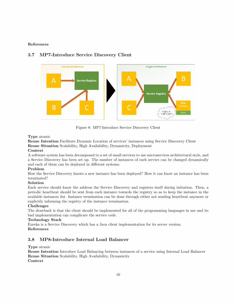
Figure 8: MP7-Introduce Service Discovery Client
Type atomicReuse Intention Facilitate Dynamic Location of services’ instances using Service Discovery ClientReuse Situation Scalability, High Availability, Dynamicity, DeploymentContextA software system has been decomposed to a set of small services to use microservices architectural style, anda Service Discovery has been set up. The number of instances of each service can be changed dynamicallyand each of them can be deployed in different systems.ProblemHow the Service Discovery knows a new instance has been deployed? How it can know an instance has beenterminated?SolutionEach service should know the address the Service Discovery and registers itself during initiation. Then, aperiodic heartbeat should be sent from each instance towards the registry so as to keep the instance in theavailable instances list. Instance termination can be done through either not sending heartbeat anymore orexplicitly informing the registry of the instance termination.ChallengesThe drawback is that the client should be implemented for all of the programming languages in use and itsbad implementation can complicate the service code.Technology StackEureka is a Service Discovery which has a Java client implementation for its server version.References
3.8 MP8-Introduce Internal Load Balancer
Type atomicReuse Intention Introduce Load Balancing between instances of a service using Internal Load BalancerReuse Situation Scalability, High Availability, DynamicityContext
10
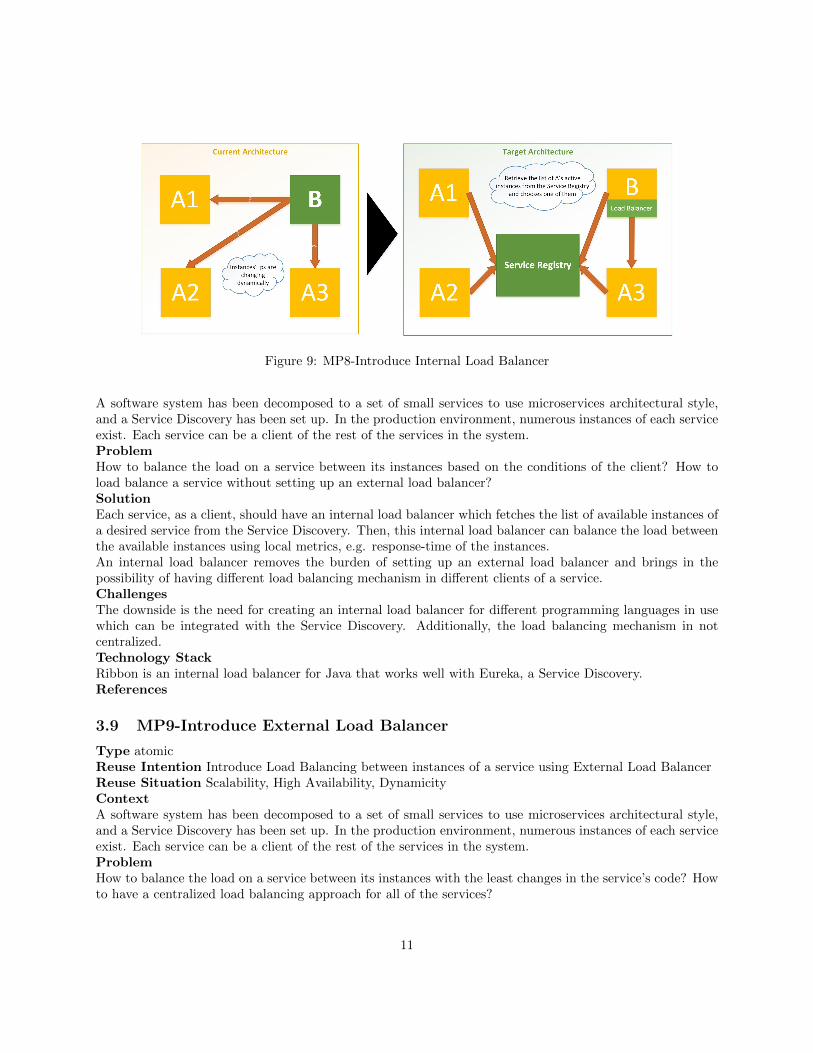
Figure 9: MP8-Introduce Internal Load Balancer
A software system has been decomposed to a set of small services to use microservices architectural style,and a Service Discovery has been set up. In the production environment, numerous instances of each serviceexist. Each service can be a client of the rest of the services in the system.ProblemHow to balance the load on a service between its instances based on the conditions of the client? How toload balance a service without setting up an external load balancer?SolutionEach service, as a client, should have an internal load balancer which fetches the list of available instances ofa desired service from the Service Discovery. Then, this internal load balancer can balance the load betweenthe available instances using local metrics, e.g. response-time of the instances.An internal load balancer removes the burden of setting up an external load balancer and brings in thepossibility of having different load balancing mechanism in different clients of a service.ChallengesThe downside is the need for creating an internal load balancer for different programming languages in usewhich can be integrated with the Service Discovery. Additionally, the load balancing mechanism in notcentralized.Technology StackRibbon is an internal load balancer for Java that works well with Eureka, a Service Discovery.References
3.9 MP9-Introduce External Load Balancer
Type atomicReuse Intention Introduce Load Balancing between instances of a service using External Load BalancerReuse Situation Scalability, High Availability, DynamicityContextA software system has been decomposed to a set of small services to use microservices architectural style,and a Service Discovery has been set up. In the production environment, numerous instances of each serviceexist. Each service can be a client of the rest of the services in the system.ProblemHow to balance the load on a service between its instances with the least changes in the service’s code? Howto have a centralized load balancing approach for all of the services?
11
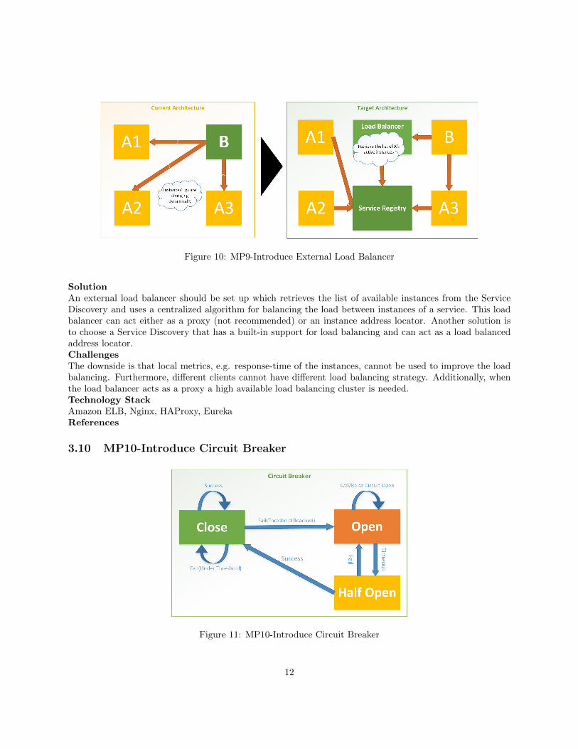
Figure 10: MP9-Introduce External Load Balancer
SolutionAn external load balancer should be set up which retrieves the list of available instances from the ServiceDiscovery and uses a centralized algorithm for balancing the load between instances of a service. This loadbalancer can act either as a proxy (not recommended) or an instance address locator. Another solution isto choose a Service Discovery that has a built-in support for load balancing and can act as a load balancedaddress locator.ChallengesThe downside is that local metrics, e.g. response-time of the instances, cannot be used to improve the loadbalancing. Furthermore, different clients cannot have different load balancing strategy. Additionally, whenthe load balancer acts as a proxy a high available load balancing cluster is needed.Technology StackAmazon ELB, Nginx, HAProxy, EurekaReferences
3.10 MP10-Introduce Circuit Breaker
Figure 11: MP10-Introduce Circuit Breaker
12
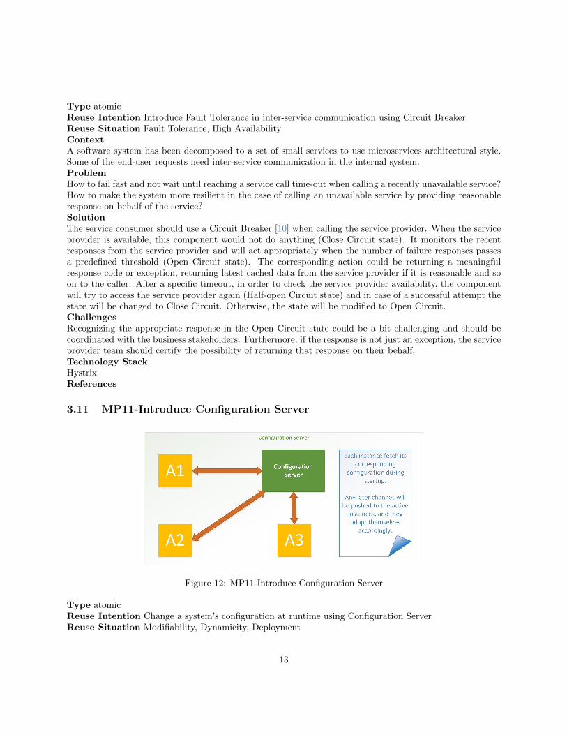
Type atomicReuse Intention Introduce Fault Tolerance in inter-service communication using Circuit BreakerReuse Situation Fault Tolerance, High AvailabilityContextA software system has been decomposed to a set of small services to use microservices architectural style.Some of the end-user requests need inter-service communication in the internal system.ProblemHow to fail fast and not wait until reaching a service call time-out when calling a recently unavailable service?How to make the system more resilient in the case of calling an unavailable service by providing reasonableresponse on behalf of the service?SolutionThe service consumer should use a Circuit Breaker [10] when calling the service provider. When the serviceprovider is available, this component would not do anything (Close Circuit state). It monitors the recentresponses from the service provider and will act appropriately when the number of failure responses passesa predefined threshold (Open Circuit state). The corresponding action could be returning a meaningfulresponse code or exception, returning latest cached data from the service provider if it is reasonable and soon to the caller. After a specific timeout, in order to check the service provider availability, the componentwill try to access the service provider again (Half-open Circuit state) and in case of a successful attempt thestate will be changed to Close Circuit. Otherwise, the state will be modified to Open Circuit.ChallengesRecognizing the appropriate response in the Open Circuit state could be a bit challenging and should becoordinated with the business stakeholders. Furthermore, if the response is not just an exception, the serviceprovider team should certify the possibility of returning that response on their behalf.Technology StackHystrixReferences
3.11 MP11-Introduce Configuration Server
Figure 12: MP11-Introduce Configuration Server
Type atomicReuse Intention Change a system’s configuration at runtime using Configuration ServerReuse Situation Modifiability, Dynamicity, Deployment
13
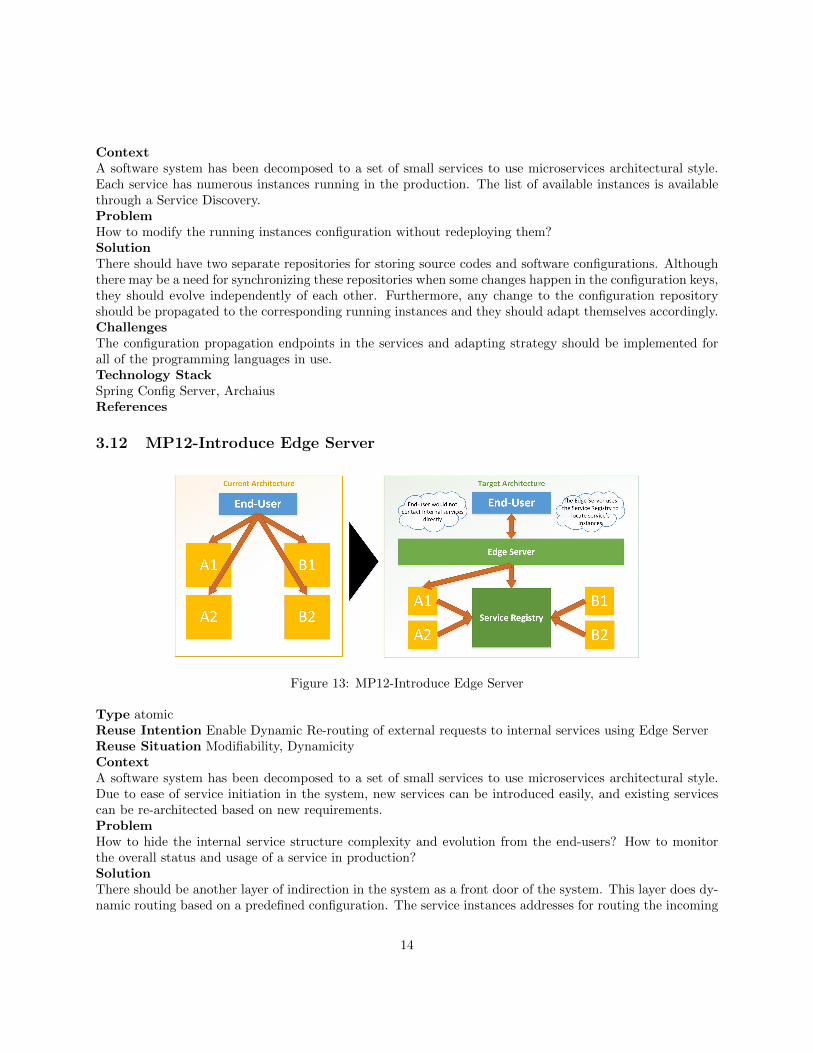
ContextA software system has been decomposed to a set of small services to use microservices architectural style.Each service has numerous instances running in the production. The list of available instances is availablethrough a Service Discovery.ProblemHow to modify the running instances configuration without redeploying them?SolutionThere should have two separate repositories for storing source codes and software configurations. Althoughthere may be a need for synchronizing these repositories when some changes happen in the configuration keys,they should evolve independently of each other. Furthermore, any change to the configuration repositoryshould be propagated to the corresponding running instances and they should adapt themselves accordingly.ChallengesThe configuration propagation endpoints in the services and adapting strategy should be implemented forall of the programming languages in use.Technology StackSpring Config Server, ArchaiusReferences
3.12 MP12-Introduce Edge Server
Figure 13: MP12-Introduce Edge Server
Type atomicReuse Intention Enable Dynamic Re-routing of external requests to internal services using Edge ServerReuse Situation Modifiability, DynamicityContextA software system has been decomposed to a set of small services to use microservices architectural style.Due to ease of service initiation in the system, new services can be introduced easily, and existing servicescan be re-architected based on new requirements.ProblemHow to hide the internal service structure complexity and evolution from the end-users? How to monitorthe overall status and usage of a service in production?SolutionThere should be another layer of indirection in the system as a front door of the system. This layer does dy-namic routing based on a predefined configuration. The service instances addresses for routing the incoming
14
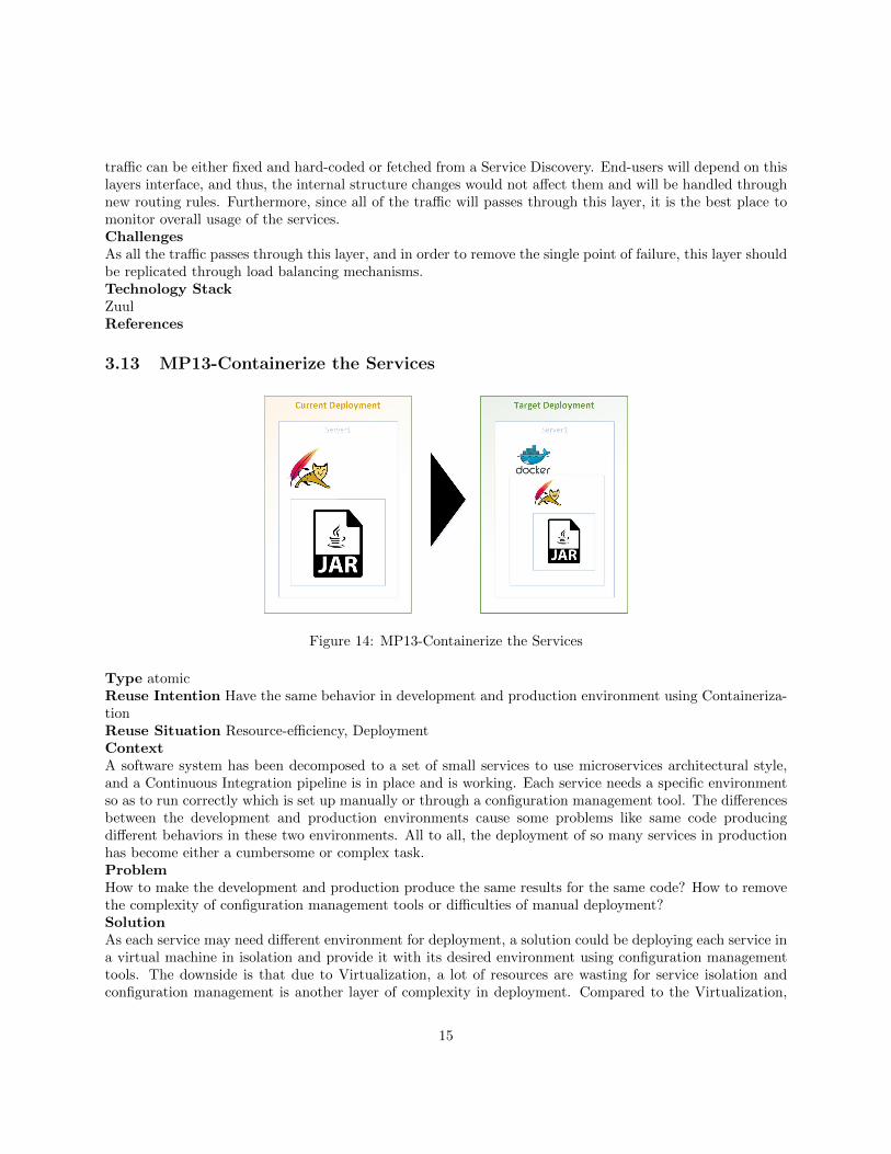
traffic can be either fixed and hard-coded or fetched from a Service Discovery. End-users will depend on thislayers interface, and thus, the internal structure changes would not affect them and will be handled throughnew routing rules. Furthermore, since all of the traffic will passes through this layer, it is the best place tomonitor overall usage of the services.ChallengesAs all the traffic passes through this layer, and in order to remove the single point of failure, this layer shouldbe replicated through load balancing mechanisms.Technology StackZuulReferences
3.13 MP13-Containerize the Services
Figure 14: MP13-Containerize the Services
Type atomicReuse Intention Have the same behavior in development and production environment using Containeriza-tionReuse Situation Resource-efficiency, DeploymentContextA software system has been decomposed to a set of small services to use microservices architectural style,and a Continuous Integration pipeline is in place and is working. Each service needs a specific environmentso as to run correctly which is set up manually or through a configuration management tool. The differencesbetween the development and production environments cause some problems like same code producingdifferent behaviors in these two environments. All to all, the deployment of so many services in productionhas become either a cumbersome or complex task.ProblemHow to make the development and production produce the same results for the same code? How to removethe complexity of configuration management tools or difficulties of manual deployment?SolutionAs each service may need different environment for deployment, a solution could be deploying each service ina virtual machine in isolation and provide it with its desired environment using configuration managementtools. The downside is that due to Virtualization, a lot of resources are wasting for service isolation andconfiguration management is another layer of complexity in deployment. Compared to the Virtualization,
15
the Containerization is more lightweight and it can remove the need for configuration management toolssince there are a lot of ready images in the central repositories containing different applications, and anyfurther configuration can be done in new images building stage.In order to make it happen, add another step to the Continuous Integration pipeline to build container imagesand store the images in a private image repository. After that, these images can be ran in both productionand development environments producing the same behavior. Each service should have its container imagecreations configuration and the script for running any other required services containers inside its coderepository.It is a good practice to add environment variables as a high priority source for populating the softwareconfiguration. In this way, the configuration keys that can have different values in different environments,e.g. database URL or any credentials, and they can be injected easily in container creation phase. Having alist of required environment variables for running a service in its code repository is a good practice and canmake anyone aware of these changing variables.ChallengesContainerization could introduce computational overhead in comparison to deployment directly to an OS infavor of a lightweight, isolated and reproducible environment. Furthermore, the development environmentshould be adapted to embrace containers.Technology StackDockerReferences
3.14 MP14-Deploy into a Cluster and Orchestrate Containers
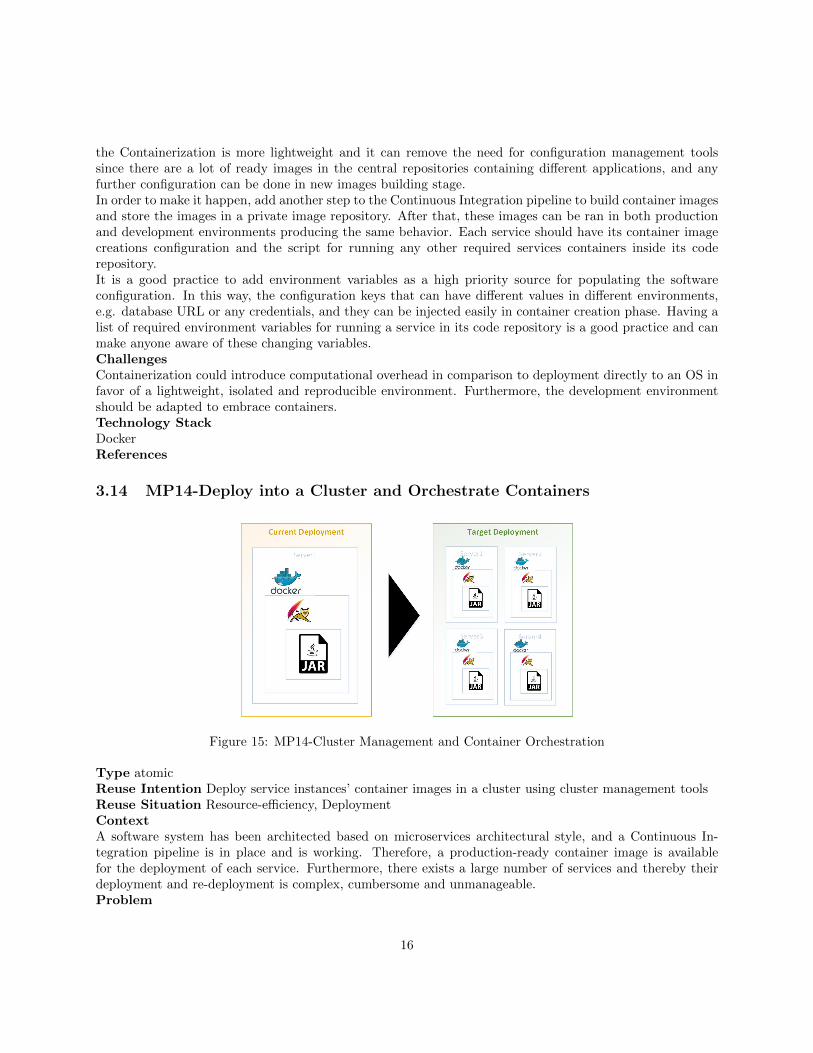
Figure 15: MP14-Cluster Management and Container Orchestration
Type atomicReuse Intention Deploy service instances’ container images in a cluster using cluster management toolsReuse Situation Resource-efficiency, DeploymentContextA software system has been architected based on microservices architectural style, and a Continuous In-tegration pipeline is in place and is working. Therefore, a production-ready container image is availablefor the deployment of each service. Furthermore, there exists a large number of services and thereby theirdeployment and re-deployment is complex, cumbersome and unmanageable.Problem
16
How to deploy a service’s instances into a cluster? How to orchestrate the deployment and re-deployment ofall of the services with the least effort?SolutionThere should exists a system that can manage a cluster of computing nodes. This management systemshould be able to deploy the services container images on-demand, with specified number of instances andon different nodes. Additionally, it should handle the failure of instances and restart the failed nodes orinstances in case. Still, it should provide a mean for auto-scaling of the services. Having an internal nameresolution strategy could be a good feature as some services such as Service Discovery should be identifiedusing name instead of an IP address.In order to effectively orchestrate the deployment process, the cluster management tool should providea mean to define the deployment architecture of services declaratively. Having a declarative deploymentarchitecture, any additional effort for deployment, e.g. auto-scaling and failure-management of the deployedservices, should be delegated to the cluster management tool.ChallengesNoneTechnology StackMesos+Marathon, KubernetesReferences
3.15 MP15-Monitor the System and Provide Feedback
Type atomicReuse Intention Monitor the running services’ instances and Provide feeback to the development teamReuse Situation Monitoring, ModifiabilityContextA software system has been architected based on microservices architectural style. The whole system isbeing ran on a cluster of containers with each service having a number of instances in production.ProblemHow to monitor the underlying infrastructure? How to use the gathered data to re-architect the system byproviding feedbacks to the development team?SolutionEach service should have its independent monitoring facility owned by the Ops part of the services team.These facilities includes the required components to gather the monitoring information, e.g. CPU and RAMusage, and sending them to a monitoring server. Therefore, the following components should be added toeach service containers image and be configured during either creation of container images or creation ofactual containers. Then, in the monitoring server, these information should be parsed and aggregated into astructured information and stored somewhere that can be queried efficiently, e.g. an indexing server. Havinga pool of timely monitoring information, a visualization tool can be used to get an overall status of thesystem. This information helps the Dev part of the service’s team to refactor the architecture in order toremove the performance bottlenecks or other detected anomalies.ChallengesNoneTechnology StackCollectd+Logstash+ElasticSearch+KibanaReferences
17
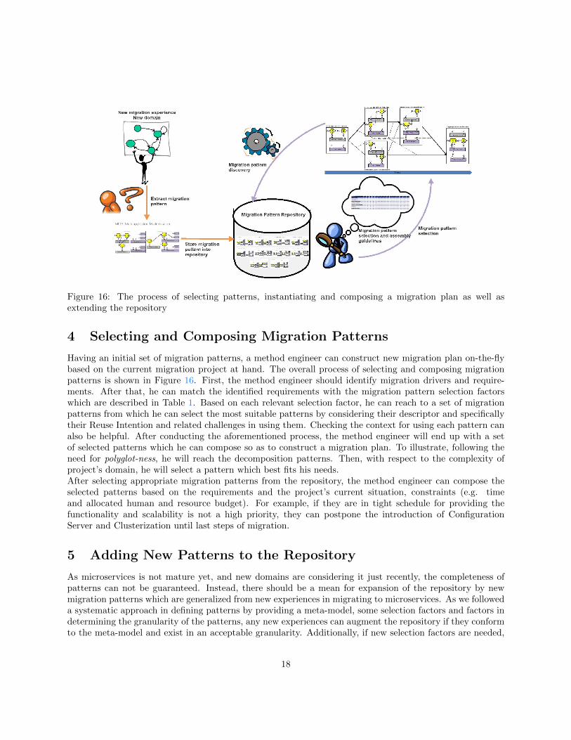
Figure 16: The process of selecting patterns, instantiating and composing a migration plan as well asextending the repository
4 Selecting and Composing Migration Patterns
Having an initial set of migration patterns, a method engineer can construct new migration plan on-the-flybased on the current migration project at hand. The overall process of selecting and composing migrationpatterns is shown in Figure 16. First, the method engineer should identify migration drivers and require-ments. After that, he can match the identified requirements with the migration pattern selection factorswhich are described in Table 1. Based on each relevant selection factor, he can reach to a set of migrationpatterns from which he can select the most suitable patterns by considering their descriptor and specificallytheir Reuse Intention and related challenges in using them. Checking the context for using each pattern canalso be helpful. After conducting the aforementioned process, the method engineer will end up with a setof selected patterns which he can compose so as to construct a migration plan. To illustrate, following theneed for polyglot-ness, he will reach the decomposition patterns. Then, with respect to the complexity ofproject’s domain, he will select a pattern which best fits his needs.After selecting appropriate migration patterns from the repository, the method engineer can compose theselected patterns based on the requirements and the project’s current situation, constraints (e.g. timeand allocated human and resource budget). For example, if they are in tight schedule for providing thefunctionality and scalability is not a high priority, they can postpone the introduction of ConfigurationServer and Clusterization until last steps of migration.
5 Adding New Patterns to the Repository
As microservices is not mature yet, and new domains are considering it just recently, the completeness ofpatterns can not be guaranteed. Instead, there should be a mean for expansion of the repository by newmigration patterns which are generalized from new experiences in migrating to microservices. As we followeda systematic approach in defining patterns by providing a meta-model, some selection factors and factors indetermining the granularity of the patterns, any new experiences can augment the repository if they conformto the meta-model and exist in an acceptable granularity. Additionally, if new selection factors are needed,
18
they can be added to the current factors.
References
[1] M. Fowler and J. Lewis, “Microservices.” http://martinfowler.com/articles/microservices.html,March 2014. [Last accessed 3-October-2015].
[2] A. Balalaie, A. Heydarnoori, and P. Jamshidi, “Migrating to cloud-native architectures using microser-vices: An experience report,” in 1st International Workshop on Cloud Adoption and Migration (Cloud-Way, (Taormina, Italy), September 2015.
[3] P. Jamshidi, A. Ahmad, and C. Pahl, “Cloud migration research: A systematic review,” IEEE Trans-actions on Cloud Computing, vol. 1, pp. 142–157, July 2013.
[4] B. Henderson-Sellers, J. Ralyt, P. Agerfalk, and M. Rossi, Situational Method Engineering. Springer-Verlag Berlin Heidelberg, 2014.
[5] M. Gholami, M. Sharifi, and P. Jamshidi, “Enhancing the open process framework with service-orientedmethod fragments,” Software & Systems Modeling, vol. 13, no. 1, pp. 361–390, 2014.
[6] P. Jamshidi, C. Pahl, S. Chinenyeze, and X. Liu, “Cloud migration patterns: A multi-cloud architecturalperspective,” in 10th International Workshop on Engineering Service-Oriented Applications (WESOA),2014.
[7] B. Henderson-Sellers, C. Gonzalez-Perez, and J. Ralyte, “Comparison of method chunks and methodfragments for situational method engineering,” in 19th Australian Conference on Software Engineering(ASWEC), pp. 479–488, March 2008.
[8] I. Mirbel and J. Ralyt, “Situational method engineering: combining assembly-based and roadmap-drivenapproaches,” Requirements Engineering, vol. 11, no. 1, pp. 58–78, 2006.
[9] N. Prat, “Goal formalisation and classification for requirements engineering,” in Requirements Engi-neering:Foundation for Software Quality, (Spain), p. 1, 1997.
[10] M. Nygard, Release It!: Design and Deploy Production-Ready Software. Pragmatic Bookshelf, 2007.
19