MICROSENSE TRAFFIC CONTROLLER CONFIGURATOR HANDBOOK
152
Doc No: 40-9009-011 Iss 3 MTC Configurator Handbook File: Handbook 9009011Iss3.doc Microsense Systems Limited 2000 Page 1 of 152 MICROSENSE TRAFFIC CONTROLLER CONFIGURATOR HANDBOOK
Transcript of MICROSENSE TRAFFIC CONTROLLER CONFIGURATOR HANDBOOK

Doc No: 40-9009-011 Iss 3 MTC Configurator Handbook
File: Handbook 9009011Iss3.doc Microsense Systems Limited 2000 Page 1 of 152
MICROSENSE TRAFFIC CONTROLLER
CONFIGURATOR HANDBOOK

MTC Configurator Handbook Doc No: 40-9009-011 Iss 3
Page 2 of 152 Microsense Systems Limited 2000 File: Handbook 9009011Iss3.doc
LEFT INTENTIONALLY BLANK

Doc No: 40-9009-011 Iss 3 MTC Configurator Handbook
File: Handbook 9009011Iss3.doc Microsense Systems Limited 2000 Page 3 of 152
DOCUMENT ISSUE HISTORY
ISSUE DATE CHANGE/ECN NUMBER
1 19/06/1999 First Issue
2 25/02/1999 ECN 99175
3 25/03/2000 ECN 00230
Microsense Systems Limited The copyright in this document is vested in Microsense Systems Limited. It may not be reproduced in whole or in part in any form without the prior consent of Microsense Systems Limited, and then only on condition that this notice is included in any reproduction. Unless otherwise expressly stated, neither this document nor any information contained in it shall be deemed to form part of a binding offer or contract on the part of Microsense Systems Limited. Microsense Systems Limited reserves the right to alter without notice any information in this document in pursuit of its policy of continued product improvement and enhancement.

MTC Configurator Handbook Doc No: 40-9009-011 Iss 3
Page 4 of 152 Microsense Systems Limited 2000 File: Handbook 9009011Iss3.doc
TABLE OF CONTENTS 1. INTRODUCTION ................................................................................................................................... 9
1.1 General ........................................................................................................................................... 9 1.2 Abbreviations and Terms .............................................................................................................. 10
2. INSTALLATION ................................................................................................................................... 11 2.1 General ......................................................................................................................................... 11 2.2 System Requirements ................................................................................................................... 11 2.3 Installation Procedure ................................................................................................................... 12 2.4 Installation Screens ....................................................................................................................... 13 2.5 Important Notes ............................................................................................................................ 15 2.6 Getting Started .............................................................................................................................. 15
3. USING THE CONFIGURATOR ........................................................................................................... 16 3.1 Configurator Start-up Screen ........................................................................................................ 16 3.2 Obtaining Help .............................................................................................................................. 17 3.3 File Menu ...................................................................................................................................... 18
3.3.1 New Configuration ................................................................................................................ 18 3.3.2 Edit Configuration ................................................................................................................. 18 3.3.3 Delete Configuration ............................................................................................................. 18 3.3.4 Export Configuration ............................................................................................................. 18 3.3.5 Print Configuration ................................................................................................................ 19 3.3.6 Exit command....................................................................................................................... 19
3.4 Convert Menu ................................................................................................................................ 20 3.4.1 Compile To Hex File ............................................................................................................. 20 3.4.2 Decompile From Hex File ..................................................................................................... 20 3.4.3 Change Format .................................................................................................................... 20 3.4.4 Import MOVA Data ............................................................................................................... 20
3.5 Data Area Menu ............................................................................................................................ 21 3.5.1 Change Area ........................................................................................................................ 21 3.5.2 Next Area ............................................................................................................................. 21 3.5.3 Previous Area ....................................................................................................................... 21 3.5.4 Next Screen .......................................................................................................................... 21 3.5.5 Previous Screen ................................................................................................................... 21 3.5.6 Change Screen .................................................................................................................... 21 3.5.7 Finish Editing ........................................................................................................................ 21
3.6 Item Menu ..................................................................................................................................... 22 3.6.1 First Item .............................................................................................................................. 22 3.6.2 Previous Item ....................................................................................................................... 22 3.6.3 Next Item .............................................................................................................................. 22 3.6.4 Last Item ............................................................................................................................... 22 3.6.5 Add Item ............................................................................................................................... 22 3.6.6 Delete Item ........................................................................................................................... 22 3.6.7 Refresh Item ......................................................................................................................... 22
3.7 View Menu .................................................................................................................................... 24 3.7.1 Toolbar ................................................................................................................................. 24 3.7.2 Status Bar ............................................................................................................................. 24 3.7.3 Compilation Errors ................................................................................................................ 24
3.8 Help Menu ..................................................................................................................................... 25 3.8.1 Contents ............................................................................................................................... 25 3.8.2 Using Help ............................................................................................................................ 25 3.8.3 About the Configurator ......................................................................................................... 25 3.8.4 Obtaining Technical Support ................................................................................................ 25
4. EDITING A CONFIGURATION ........................................................................................................... 26 4.1 General ......................................................................................................................................... 26 4.2 General Data Area ........................................................................................................................ 27
4.2.1 Screen 1 ............................................................................................................................... 27 4.2.2 Screen 2 ............................................................................................................................... 28 4.2.3 Screen 3 ............................................................................................................................... 30
4.3 Real Phase Data Area (TR0141A Format Configurations) ........................................................... 31 4.3.1 General ................................................................................................................................. 31 4.3.2 Phase Id ............................................................................................................................... 31

Doc No: 40-9009-011 Iss 3 MTC Configurator Handbook
File: Handbook 9009011Iss3.doc Microsense Systems Limited 2000 Page 5 of 152
4.3.3 Sequence Type .................................................................................................................... 31 4.3.4 Road Name .......................................................................................................................... 31 4.3.5 Appearance Type ................................................................................................................. 32 4.3.6 Termination Type ................................................................................................................. 32 4.3.7 Restart Allowed .................................................................................................................... 32 4.3.8 Appearance In Manual ......................................................................................................... 32 4.3.9 Minimum Green ................................................................................................................... 33 4.3.10 Min Green Limit Value ......................................................................................................... 33 4.3.11 Ped Blackout ........................................................................................................................ 33 4.3.12 Ped Blackout Limit Value ..................................................................................................... 33 4.3.13 Window Time ....................................................................................................................... 33 4.3.14 Conditional Demand Type ................................................................................................... 33 4.3.15 Conditioning Phases ............................................................................................................ 33 4.3.16 Maximum Greens ................................................................................................................ 33 4.3.17 Varimax Required ................................................................................................................ 33 4.3.18 Varimax Additional Period .................................................................................................... 33 4.3.19 Varimax Threshold Flow ...................................................................................................... 33 4.3.20 Conflicting Greens ............................................................................................................... 34 4.3.21 Opposed By Phase Demands .............................................................................................. 34 4.3.22 Opposed By Stage Demands .............................................................................................. 34 4.3.23 Revertive Phase Demands .................................................................................................. 34
4.4 Real Phase Data Area (TR0141C Format Configurations) .......................................................... 35 4.4.1 Screen 1 ............................................................................................................................... 35 4.4.2 Screen 2 (Traffic Sequence) ................................................................................................ 39 4.4.3 Screen 2 (Pedestrian Sequence) ......................................................................................... 41
4.5 Dummy Phase Data Area (TR0141A Format Configurations) ..................................................... 46 4.5.1 General ................................................................................................................................ 46 4.5.2 Phase Id/Dummy Name ....................................................................................................... 46
4.6 Dummy Phase Data Area (TR0141C Format Configurations) ..................................................... 47 4.6.1 Screen 1 ............................................................................................................................... 47 4.6.2 Screen 2 (Traffic Sequence) ................................................................................................ 48 4.6.3 Screen 2 (Pedestrian Sequence) ......................................................................................... 49
4.7 Lamp Sequence Data Area .......................................................................................................... 50 4.7.1 General ................................................................................................................................ 50 4.7.2 Mode Of Operation (TR0141C Format Configurations Only) .............................................. 51
4.8 Stage Data Area ........................................................................................................................... 52 4.8.1 General ................................................................................................................................ 52 4.8.2 Start-Up Stage Number ....................................................................................................... 52 4.8.3 Number Of Stages ............................................................................................................... 52 4.8.4 List Active Phases ................................................................................................................ 52 4.8.5 Stand Alone Pedestrian Stream (TR0141C Format Configurations Only) ........................... 52
4.9 Switched Sign Data Area .............................................................................................................. 53 4.9.1 General ................................................................................................................................ 53 4.9.2 UTC Reply Bit Name ............................................................................................................ 53 4.9.3 Switched Signs With Security .............................................................................................. 53 4.9.4 Conflicting Phase Greens .................................................................................................... 53 4.9.5 Switch On/Off Stage/Phase ................................................................................................. 54 4.9.6 Associated With Stream ...................................................................................................... 54 4.9.7 Phase Drive Used ................................................................................................................ 54 4.9.8 Associated LRT Phase(s) .................................................................................................... 54
4.10 Mode Priority Data Area ............................................................................................................... 55 4.10.1 General ................................................................................................................................ 55 4.10.2 Priority No. ........................................................................................................................... 55 4.10.3 A/R Extensions Auto To Max (Y/N) ...................................................................................... 55 4.10.4 List Phase Demands To Be Inserted .... .............................................................................. 55 4.10.5 Starting Intergreen Duration ................................................................................................. 55
4.11 Part-Time Mode Data Area ........................................................................................................... 57 4.11.1 General ................................................................................................................................ 57 4.11.2 Switch-Off Stage .................................................................................................................. 57 4.11.3 Prevent Period ..................................................................................................................... 57 4.11.4 Hold Period .......................................................................................................................... 57 4.11.5 Part-Time Queue Detectors ................................................................................................. 58
4.12 Hurry Call Mode Data Area ........................................................................................................... 59

MTC Configurator Handbook Doc No: 40-9009-011 Iss 3
Page 6 of 152 Microsense Systems Limited 2000 File: Handbook 9009011Iss3.doc
4.12.1 General ................................................................................................................................. 59 4.12.2 Call Stage ............................................................................................................................. 59 4.12.3 Request Detectors ................................................................................................................ 59 4.12.4 Cancel Detectors .................................................................................................................. 60 4.12.5 Confirm O/P Name ............................................................................................................... 60 4.12.6 Delay Period ......................................................................................................................... 60 4.12.7 Hold Period ........................................................................................................................... 60 4.12.8 Prevent Period ...................................................................................................................... 60
4.13 Manual Mode Data Area ............................................................................................................... 61 4.13.1 General ................................................................................................................................. 61 4.13.2 Stage Number For Each Stream .......................................................................................... 61 4.13.3 Street Names ....................................................................................................................... 61 4.13.4 Enter Button Number For Initial Manual Stage Set .............................................................. 61 4.13.5 Streams That Must Be In Manual Mode Together ............................................................... 61
4.14 UTC Mode Data Area.................................................................................................................... 62 4.14.1 Screen 1 ............................................................................................................................... 62 4.14.2 Screen 2 ............................................................................................................................... 65 4.14.3 Screen 3 ............................................................................................................................... 66 4.14.4 Screen 4 ............................................................................................................................... 67 4.14.5 Screen 5 ............................................................................................................................... 68 4.14.6 Screen 6 ............................................................................................................................... 69 4.14.7 Screen 7 ............................................................................................................................... 70 4.14.8 Screen 8 (TR0141C Format Configurations Only) ............................................................... 71 4.14.9 Screen 9 (TR0141C Format Configurations Only) ............................................................... 72 4.14.10 Screen 10 (Screen 8 for TR0141A Configurations).............................................................. 73
4.15 FT/VA Mode Data Area ................................................................................................................. 74 4.15.1 General ................................................................................................................................. 74 4.15.2 FT Mode ............................................................................................................................... 74 4.15.3 FT Mode/Timed Option ........................................................................................................ 74 4.15.4 FT Mode/VA To Current Maxes Option (TR0141A Format Configurations Only) ................ 75 4.15.5 VA Mode ............................................................................................................................... 75
4.16 CLF Mode Data Area .................................................................................................................... 76 4.16.1 General ................................................................................................................................. 76 4.16.2 Delay Time ........................................................................................................................... 76 4.16.3 Cycle Time ........................................................................................................................... 76 4.16.4 Stream Offset Time .............................................................................................................. 76 4.16.5 Stream Time ......................................................................................................................... 77 4.16.6 Stream Influence .................................................................................................................. 77 4.16.7 Stream Stage ....................................................................................................................... 77
4.17 Stage To Stage Movement Data Area .......................................................................................... 78 4.17.1 Screen 1 ............................................................................................................................... 78 4.17.2 Screen 2 ............................................................................................................................... 79
4.18 Intergreen Data Area ..................................................................................................................... 80 4.18.1 Screen 1 ............................................................................................................................... 80 4.18.2 Screen 2 ............................................................................................................................... 81 4.18.3 Screen 3 ............................................................................................................................... 82
4.19 Phase Delay Data Area ................................................................................................................. 83 4.19.1 General ................................................................................................................................. 83 4.19.2 Losing/Gaining Stage ........................................................................................................... 83 4.19.3 Assoc Phase ........................................................................................................................ 83 4.19.4 Delay Period ......................................................................................................................... 83
4.20 Detector Data Area (TR0141A Format Configurations) ................................................................ 84
4.20.1 General ................................................................................................................................. 84 4.20.2 Name .................................................................................................................................... 84 4.20.3 Detector Type ....................................................................................................................... 84 4.20.4 Count Detector ..................................................................................................................... 84 4.20.5 Input No. ............................................................................................................................... 85 4.20.6 Assoc Input No. .................................................................................................................... 85 4.20.7 Assoc VIS Unit No. ............................................................................................................... 85 4.20.8 Active State .......................................................................................................................... 85 4.20.9 Illuminate Wait Lamps On Phases ....................................................................................... 85 4.20.10 Latched/Unlatched Phase Demands .................................................................................... 85

Doc No: 40-9009-011 Iss 3 MTC Configurator Handbook
File: Handbook 9009011Iss3.doc Microsense Systems Limited 2000 Page 7 of 152
4.20.11 Green Phase Extensions ..................................................................................................... 85 4.20.12 Varimax Phases ................................................................................................................... 85 4.20.13 DFM Force State .................................................................................................................. 86 4.20.14 DFM Timings ........................................................................................................................ 86 4.20.15 Call Cancel Timings ............................................................................................................. 86
4.21 Detector Data Area (TR0141C Format Configurations) ............................................................... 87 4.21.1 General ................................................................................................................................ 87 4.21.2 Name ................................................................................................................................... 87 4.21.3 Detector Type ...................................................................................................................... 87 4.21.4 Count Detector ..................................................................................................................... 87 4.21.5 Input No. .............................................................................................................................. 88 4.21.6 Assoc Input No. .................................................................................................................... 88 4.21.7 Assoc VIS Unit No. .............................................................................................................. 88 4.21.8 Active State .......................................................................................................................... 88 4.21.9 Illuminate Wait Lamps On Phases ...................................................................................... 88 4.21.10 Latched/Unlatched Phase Demands ................................................................................... 88 4.21.11 Green Phase Extensions ..................................................................................................... 88 4.21.12 Varimax Phases ................................................................................................................... 88 4.21.13 DFM Force State .................................................................................................................. 89 4.21.14 DFM Timings ........................................................................................................................ 89 4.21.15 Call Cancel Timings ............................................................................................................. 89 4.21.16 Pedestrian Information ......................................................................................................... 89
4.22 All Red Extension Data Area ........................................................................................................ 90 4.22.1 General ................................................................................................................................ 90 4.22.2 All Red Maximum Time ........................................................................................................ 90 4.22.3 Assoc Stream....................................................................................................................... 90 4.22.4 Losing/Gaining Stage ........................................................................................................... 90 4.22.5 Assoc Detector ..................................................................................................................... 90 4.22.6 Extension Time .................................................................................................................... 90
4.23 Intergreen Extension Data Area ................................................................................................... 92 4.23.1 General ................................................................................................................................ 92 4.23.2 Losing/Gaining Phase .......................................................................................................... 92 4.23.3 Assoc Detector ..................................................................................................................... 92 4.23.4 Extension Time .................................................................................................................... 92
4.24 Timetable Entry Data Area ........................................................................................................... 93 4.24.1 General ................................................................................................................................ 93 4.24.2 Day Type .............................................................................................................................. 93 4.24.3 Time Of Day ......................................................................................................................... 94 4.24.4 Event List No. ....................................................................................................................... 94 4.24.5 User-Defined Day Types ...................................................................................................... 94
4.25 Timetable Event List Data Area .................................................................................................... 95 4.25.1 General ................................................................................................................................ 95 4.25.2 Type ..................................................................................................................................... 95 4.25.3 Parameters .......................................................................................................................... 96
4.26 Special Conditioning Data Area .................................................................................................... 97 4.26.1 Screen 1 ............................................................................................................................... 97 4.26.2 Screen 2 ............................................................................................................................. 108 4.26.3 Screen 3 ............................................................................................................................. 109 4.26.4 Special Conditioning Examples ......................................................................................... 110
4.27 Red Lamp Monitoring Data Area ................................................................................................ 118 4.27.1 Screen 1 ............................................................................................................................. 118 4.27.2 Screen 2 ............................................................................................................................. 120 4.27.3 Screen 3 ............................................................................................................................. 121
4.28 MOVA Data Area ........................................................................................................................ 122 4.28.1 Screen 1 ............................................................................................................................. 122 4.28.2 Screen 2 ............................................................................................................................. 124 4.28.3 Screen 3 ............................................................................................................................. 126 4.28.4 Screen 4 ............................................................................................................................. 128 4.28.5 Screen 5 ............................................................................................................................. 131

MTC Configurator Handbook Doc No: 40-9009-011 Iss 3
Page 8 of 152 Microsense Systems Limited 2000 File: Handbook 9009011Iss3.doc
4.28.6 Screen 6 ............................................................................................................................. 132 4.29 LRT Mode Data Area .................................................................................................................. 134
4.29.1 Screen 1 ............................................................................................................................. 134 4.29.2 Screen 2 ............................................................................................................................. 137 4.29.3 Screen 3 ............................................................................................................................. 139 4.29.4 Screen 4 ............................................................................................................................. 140 4.29.5 Screen 5 ............................................................................................................................. 141 4.29.6 Screen 6 ............................................................................................................................. 142
4.30 Integral Lamp Monitoring Data Area ........................................................................................... 143 4.30.1 General ............................................................................................................................... 144
4.31 Input/Output Data Area Screens ................................................................................................. 146 4.31.1 Screen 1 ............................................................................................................................. 146 4.31.2 Screen 2 ............................................................................................................................. 148
5. CONFIGURATOR IMPORT/EXPORT .............................................................................................. 150 5.1 General ....................................................................................................................................... 150 5.2 Import .......................................................................................................................................... 150 5.3 Export .......................................................................................................................................... 151 5.4 Archive ........................................................................................................................................ 151 5.5 Copy ............................................................................................................................................ 151 5.6 Repair & Compact ....................................................................................................................... 151
6. PROM BLOWING .............................................................................................................................. 152
Doc No: 40-9009-011 Iss 3 MTC Configurator Handbook
File: Handbook 9009011Iss3.doc Microsense Systems Limited 2000 Page 9 of 152
1. INTRODUCTION
1.1 General
This handbook covers the installation and operation of the MTC Configurator Mk III for Windows. For
customers who have a Software Support Agreement, when changes are made to the Configurator a new
set of installation disks and a Software Release Note will be issued along with a new version of this
handbook, if applicable.
This handbook is not intended to give detailed descriptions of the facilities provided by the MTC. For this
information the user should refer to the MTC Facilities Manual, (doc no. 40-9001-009) which is available
from Microsense Systems Ltd.
The main function of the MTC Configurator is to produce an Intel Hex file, from which a Configuration
PROM can be blown, although the actual blowing of the PROM is not a function carried out by the
Configurator. This Configuration PROM can then be used in an MTC. The Configurator can also produce
a Configuration Printout, (works specification). The format of data entry screens in the MTC Configurator
is based as closely as possible on the MTC Specification Forms, (doc no. 40-9009-029 for TR0141A, or
40-9009-077 for TR0141C) which are available from Microsense Systems Ltd.
It should be noted that although this version of the Configurator supports all options currently available on
the MTC, the controller software purchased may only include a subset. Throughout this handbook it is
assumed that the user has at least a basic knowledge of Traffic Control.
N.B. Any configuration PROM produced using this package should be fully tested to ensure its correct
operation prior to installation on street.
MTC Configurator Handbook Doc No: 40-9009-011 Iss 3
Page 10 of 152 Microsense Systems Limited 2000 File: Handbook 9009011Iss3.doc
1.2 Abbreviations and Terms
Following is a list of abbreviations and terms used throughout this document :-
A/R - All Red
BST - British Summer Time
CLF - Cableless Linking Facility
DFM - Detector Fault Monitoring
FT - Fixed Time
FVP - Fixed Vehicle Period
ILM - Integral Lamp Monitoring
I/O - Input/Output
Kb - Kilobytes
LMU - Lamp Monitoring Unit
LRT - Light Rail Transit
Mb - Megabytes
MDB - Microsoft DataBase
MOVA - Microprocessor Optimised Vehicle Actuation
MTC - Microsense Traffic Controller
ODBC - Open DataBase Connectivity
OMTU - Outstation Monitoring & Transmission Unit
PROM - Programmable Read Only Memory
PTM - Pre-Timed Maximum
RLMU - Red Lamp Monitoring Unit
SA - Speed Assessment
SCF - Standard Configuration File
SCOOT - Split Cycle Offset Optimisation Technique
SD - Speed Discrimination
SMIF - Soundmark Interface Unit
TC - Transmission Confirm
TR0141 - Highway Agency Specification for Microprocessor based Traffic Signal
Controller
TRL - Transport Research Laboratory
UD - Uni-Directional
UTC - Urban Traffic Control
VA - Vehicle Actuated
VARIMAX - Variable Maximum
VPH - Vehicles per Hour
Doc No: 40-9009-011 Iss 3 MTC Configurator Handbook
File: Handbook 9009011Iss3.doc Microsense Systems Limited 2000 Page 11 of 152
2. INSTALLATION
2.1 General
The MTC Configurator installation procedure is largely self-explanatory, the software being supplied on a
CD-ROM. Note a floppy disk version is available on request.
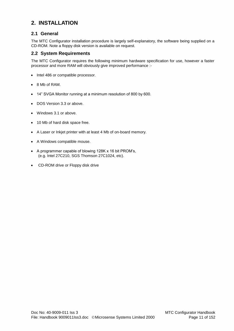
2.2 System Requirements
The MTC Configurator requires the following minimum hardware specification for use, however a faster
processor and more RAM will obviously give improved performance :-
Intel 486 or compatible processor.
8 Mb of RAM.
14” SVGA Monitor running at a minimum resolution of 800 by 600.
DOS Version 3.3 or above.
Windows 3.1 or above.
10 Mb of hard disk space free.
A Laser or Inkjet printer with at least 4 Mb of on-board memory.
A Windows compatible mouse.
A programmer capable of blowing 128K x 16 bit PROM’s,
(e.g. Intel 27C210, SGS Thomson 27C1024, etc).
CD-ROM drive or Floppy disk drive

MTC Configurator Handbook Doc No: 40-9009-011 Iss 3
Page 12 of 152 Microsense Systems Limited 2000 File: Handbook 9009011Iss3.doc
2.3 Installation Procedure
This section describes the procedure for installing the MTC Configurator.
If upgrading from an existing Configurator system the data contained in the current Configurations
database file, (C:\MTCCFG2\MTCCFG2.MDB) should not be affected, however, it would be advisable
to take a copy of it before proceeding with the installation. It is recommend that you do not install the
new version of the configurator in the same directory as the old one.
Place the MTC Configurator CD-ROM in the CD-ROM drive. Note floppy disk version is available on
request.
Run Windows. N.B. Please ensure that Windows is running in SVGA, (800 by 600) mode as both the
installation program and the Configurator itself operate best at this screen resolution.
From Program Manager select the Run option from the File menu if running Windows 3.1 or 3.11. If
using Windows 9x or 2000 then use the Start-Run menu option.
Type d:\setup.exe, (where ‘d’ is the drive letter of the cd drive) and click on the ‘Ok’ button.
The Configurator installation program will now run, (see below for diagrams of the installation
screens). If an error message occurs regarding copying of a file named ‘THREED.VBX’ then this file
must be found and renamed to ‘THREED.TMP’. This file should be in the ‘Windows’ directory (or
‘Windows\Systems’ for Windows 9x & 2000). Once installation is complete check if the new
‘THREED.VBX’ is older than the renamed one, and if it is then delete it and rename the original.
Choose a Full Installation, unless otherwise advised by a Software Release Note.
The installation program will now offer a dialogue box for the installation directory. Click on the ‘Continue’ button to retain the default, (advisable).
The Configurator files will now be installed and the user will be prompted to changes disks when
required.
The required Program Manager group and items will be created by the installation program as well as
all updates required to .INI files.
This version of the Configurator requires that SHARE /l:500 is present in the user’s AUTOEXEC.BAT
file before any call to Windows, (if non-Windows 9x or 2000) and that the FILES entry in CONFIG.SYS
is set to at least 50. The installation program will check both these items and display messages if they
are not present but it will not alter either file, this must be done by the user with a suitable text editor.
Doc No: 40-9009-011 Iss 3 MTC Configurator Handbook
File: Handbook 9009011Iss3.doc Microsense Systems Limited 2000 Page 13 of 152
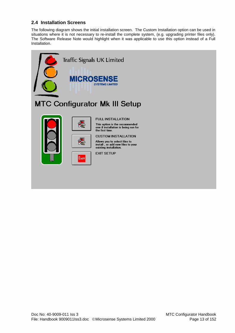
2.4 Installation Screens
The following diagram shows the initial installation screen. The Custom Installation option can be used in situations where it is not necessary to re-install the complete system, (e.g. upgrading printer files only). The Software Release Note would highlight when it was applicable to use this option instead of a Full Installation.
MTC Configurator Handbook Doc No: 40-9009-011 Iss 3
Page 14 of 152 Microsense Systems Limited 2000 File: Handbook 9009011Iss3.doc
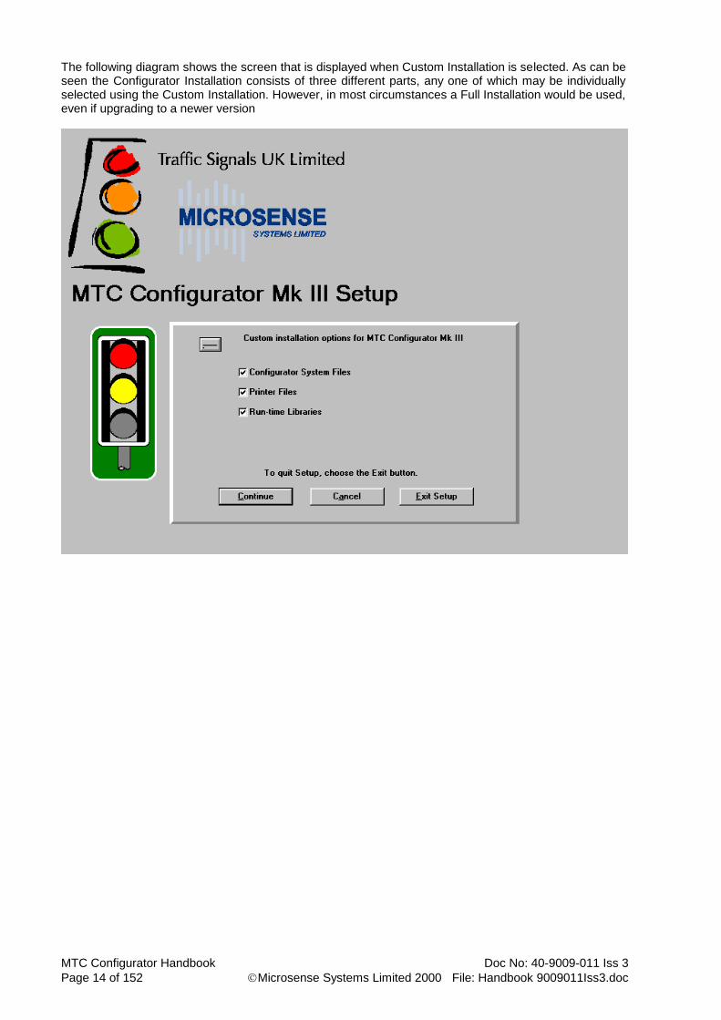
The following diagram shows the screen that is displayed when Custom Installation is selected. As can be seen the Configurator Installation consists of three different parts, any one of which may be individually selected using the Custom Installation. However, in most circumstances a Full Installation would be used, even if upgrading to a newer version

Doc No: 40-9009-011 Iss 3 MTC Configurator Handbook
File: Handbook 9009011Iss3.doc Microsense Systems Limited 2000 Page 15 of 152
2.5 Important Notes
This section details certain aspects of the Configurator installation and operation that the user should be aware of.
It is possible that some Windows Dynamic Link Libraries will report a ‘file in use’ error on installation.
The ‘Ignore’ button should be selected if this happens and the installation will then continue
If you are running Windows for Workgroups Version 3.11 or above and have selected 32-bit file access then there is no need to install SHARE in your AUTOEXEC.BAT as this version of Windows provides its own file sharing driver called VSHARE.
Never configure the ODBC Administrator to use the database file BLANK.MDB. This is an empty copy of the MTCCFG3.MDB and needs to be kept unused. Should this file be overwritten then the Configurator System files should be reinstalled via the Custom Setup option in the installation program.
Never compile a configuration to the file BLANK.HEX as this file is used as a template by the compiler and unpredictable results for compilation will follow. Should this file be overwritten then the Configurator System files should be reinstalled via the Custom Setup option in the installation program.
Always ensure that your Windows printer driver is set up to indicate the amount of memory actually installed in your printer. Failure to do so will have a detrimental effect on print speed.
2.6 Getting Started
Upon installation, the Configurator Setup program creates a new Windows program group called ‘MTC Configurator’. The group can be restored by double-clicking on it with the mouse. There are five icons present in the group, any one of which may be invoked by double-clicking on the appropriate icon. 1) The ODBC administrator allows the creation, set-up and deletion of ODBC data sources. It is
provided since the Configurator program uses an ODBC data source, but should only be invoked by an experienced Windows user.
2) The Configurator Setup program permits the re-installation of either all or parts of the
Configurator should this be necessary due to the deletion or corruption of any files. 3) The Import/Export program is a stand-alone utility that permits the user to copy configurations in
and out of the MTC Configurator system. It also allows the user to copy an existing configuration to a new one within the system.
4) Release notes is a Microsoft Write 3.11 document which provides an electronic copy of the latest
Software Release Note. 5) MTC Configurator Mk III is the main Configurator application.

MTC Configurator Handbook Doc No: 40-9009-011 Iss 3
Page 16 of 152 Microsense Systems Limited 2000 File: Handbook 9009011Iss3.doc
3. USING THE CONFIGURATOR
3.1 Configurator Start-up Screen
Having invoked the MTC Configurator MK III the following start-up screen will be displayed.
As can be seen above this screen consists of several drop-down menus at the very top, below them a toolbar, (which contains useful shortcut functions) and at the bottom a status bar.

Doc No: 40-9009-011 Iss 3 MTC Configurator Handbook
File: Handbook 9009011Iss3.doc Microsense Systems Limited 2000 Page 17 of 152
3.2 Obtaining Help
As mentioned in the previous section, a toolbar and status bar form part of the Configurator system. An indication of the function of every item on the toolbar may be found by holding the mouse over it briefly. A Microsoft ‘tooltip’ will appear, indicating the function of the relevant toolbar button. The status bar will also display a longer and more informative explanation of the button. Access to the on-line help system is available in several ways. The contents page may be accessed directly from the Help menu or by hitting the ‘F1’ key when the start-up screen is displayed. Context-sensitive help may be obtained on different screens, toolbar buttons and menu options via the toolbar button displayed below or by the shortcut key combination of ‘SHIFT-F1’.
Once this button has been clicked, the mouse cursor changes to reflect the picture on the button. The mouse should then be moved to the item help is required on and clicked. The on-line help relating to that item will then be displayed. Note that for Configurator edit screens there is one page of help relating to all items on that screen. Hard-copy of help topics is extremely easy to obtain. Once the topic is displayed under the Windows Help engine select the ‘File’ menu and the ‘Print Topic’ menu option. The currently selected help area will now be copied to your printer. There is also on-line help for using the Help system itself. This can be invoked from within the Configurator by selecting the ‘Help’ menu and the ‘Using Help’ menu option. See also the later section on the Help menu options.
MTC Configurator Handbook Doc No: 40-9009-011 Iss 3
Page 18 of 152 Microsense Systems Limited 2000 File: Handbook 9009011Iss3.doc
3.3 File Menu
The following sub-sections describe each of the options under the File drop-down menu.
3.3.1 New Configuration
Use this menu option to create a new configuration. A dialogue box will appear, where the configuration number and description should be typed in. Configuration format should also be selected from the drop-down list.
Shortcut Keys : ALT+F, N
Toolbar Item :
3.3.2 Edit Configuration
Use this menu option to edit an existing configuration. A dialogue box will appear with a drop-down combo box from which to choose the required configuration for editing. The navigator buttons may also be used to move through the list of configurations.
Shortcut Keys : ALT+F, E
Toolbar Item :
3.3.3 Delete Configuration
Use this menu option to delete a configuration. A dialogue box will appear with a drop-down combo box from which to choose the required configuration for deletion. The navigator buttons may also be used to move through the list of configurations. Once a configuration has been selected a prompt box will be displayed to confirm the deletion.
Shortcut Keys : ALT+F, D
3.3.4 Export Configuration
Use this menu option to export, (copy) a configuration in the system to an external .MDB file. A dialogue box will appear with a drop-down combo box from which to choose the required configuration for export. The navigator buttons may also be used to move through the list of configurations. When a configuration has been selected another dialogue box will be displayed for defining the name and
location of the file to export to. A default location\file name of ‘c:\mtccfg3\xxxxx.mdb’ will be given,
(where xxxxx is the Configuration number). If the chosen file name already exists then a dialogue box will be displayed asking whether you wish to overwrite the file or not.
Shortcut Keys : ALT+F, O Note that this facility is also available using the stand-alone Import/Export utility.

Doc No: 40-9009-011 Iss 3 MTC Configurator Handbook
File: Handbook 9009011Iss3.doc Microsense Systems Limited 2000 Page 19 of 152
3.3.5 Print Configuration
Use this menu option to create a configuration printout. A dialogue box will appear with a drop-down combo box from which to choose the required configuration for printing. The navigator buttons may also be used to move through the list of configurations. When a configuration has been selected the choice is given to print all forms or just selected forms. The common choice would be to print selected forms, which will then cause a drop down box to be displayed showing each of the forms available. Forms in the drop down box can be selected by either of the following two methods :- 1) Hold down the CTRL key and then click on each form required with the left hand mouse button. 2) Click on the first form then press SHIFT+F8. The up/down cursor keys can be used to move the
highlight bar and then use the spacebar to select/deselect a form.
Shortcut Keys : ALT+F, P
Toolbar Item :
3.3.6 Exit command
Use this menu option to end the current Configurator session. You can also use the close command on the application control menu, (standard windows function).
Shortcut Keys : ALT+F, X
Mouse : Double-click the application's Control menu button.
MTC Configurator Handbook Doc No: 40-9009-011 Iss 3
Page 20 of 152 Microsense Systems Limited 2000 File: Handbook 9009011Iss3.doc
3.4 Convert Menu
The following sub-sections describe each of the options under the Convert drop-down menu.
3.4.1 Compile To Hex File
Use this menu option to compile a configuration into an extended Intel hex file, suitable for blowing into a PROM. A dialogue box will appear with a drop-down combo box from which to choose the required configuration for compilation. The navigator buttons may also be used to move through the list of configurations. When a configuration has been selected another dialogue box will be displayed for defining the name and location of the hex file to compile to. Note that the file MUST be in the directory that contains the file
‘BLANK.HEX’, (this is usually C:\MTCCFG3). A default file name of ‘xxxxx.hex’ will be given, (where
xxxxx is the Configuration number). If the chosen file name already exists then a dialogue box will be displayed asking whether you wish to overwrite the file or not. The actual blowing of a configuration PROM is not performed by the Configurator, but there are some useful tips on this subject in the PROM Blowing section of this handbook. Note unlike previous marks of the configurator, if there are errors during compilation a hex file will not be produced.
Shortcut Keys : ALT+C, H
3.4.2 Decompile From Hex File
This menu option decompiles an extended Intel hex file into the configurator. A dialogue box will appear with a drop-down combo box from which to choose the required hex file to be decompiled. Another dialogue box will then be displayed, where the configuration number and description should be typed in. Decompile is mainly used for converting old interim, (hand done) configurations, which in the main have only been done by Microsense Systems Ltd. This facility only decompiles data that is stored in the PROM, therefore textual data for printout purposes, (e.g. customers name, site name, phase road names, etc) will need to be added after decompilation. Where decompilation is required this is best carried out by Microsense Systems Ltd.
Shortcut Keys : ALT+C, D
3.4.3 Change Format
This menu option converts database information between TR0141C and TR0141A formats. A dialog box will appear with a drop-down combo box from which to choose the configuration to change. Another drop-down combo box contains available formats.
Shortcut Keys : ALT+C, F
3.4.4 Import MOVA Data
This menu option is used to Import data from a TRL MOVASETUP print file, (.pr) into a chosen configuration. A dialogue box is displayed to select the ‘.pr’ file to be imported. A second dialogue box is then displayed for selecting the configuration to import the data into. The navigator buttons may also be used to move through the list of configurations. A third dialogue box will then be displayed to specify which MOVA data set to import the data into. Note that this facility imports the majority of data required for MOVA, but there are still a couple of data items that need to be entered by hand during a normal edit session.
Shortcut Keys : ALT+C, M

Doc No: 40-9009-011 Iss 3 MTC Configurator Handbook
File: Handbook 9009011Iss3.doc Microsense Systems Limited 2000 Page 21 of 152
3.5 Data Area Menu
The following sub-sections describe each of the options under the Data Area drop-down menu. Each configuration consists of a number of different data areas, each of which may contain one or more different screens. It should be noted that any change away from a data entry screen causes the data on it to be saved.
3.5.1 Change Area
This menu option displays another menu listing the available data areas, from which one may be chosen for editing.
Shortcut Keys : F2 or ALT+D, C
Toolbar Item :
3.5.2 Next Area
This menu option causes a move to the next data area, whilst editing. If you are already on the last data area then a dialogue box will be displayed informing you of this fact.
Shortcut Keys : F5 or ALT+D, X
3.5.3 Previous Area
This menu option causes a move to the previous data area, whilst editing. If you are already on the first data area then a dialogue box will be displayed informing you of this fact.
Shortcut Keys : F4 or ALT+D, V
3.5.4 Next Screen
This menu option causes a move to the next screen in the current data area, whilst editing. If the active screen is the last one for the current data area, then this item will cause a change back to the first screen.
Shortcut Keys : ALT+D, N
Toolbar Item :
3.5.5 Previous Screen
This menu option causes a move to the previous screen in the current data area, whilst editing. If the active screen is the first one for the current data area, then this item will cause a change back to the last screen.
Shortcut Keys : ALT+D, P
Toolbar Item :
3.5.6 Change Screen
This menu option displays another menu listing the available screens for the current data area, from which one may be chosen for editing.. Note that this item is only available on data areas with a large number of screens.
Shortcut Keys : ALT+D, S
3.5.7 Finish Editing
This menu option saves the data on the current screen, closes the current configuration and returns to the start-up screen.
Shortcut Keys : F3 or ALT+D, F
Toolbar Item :

MTC Configurator Handbook Doc No: 40-9009-011 Iss 3
Page 22 of 152 Microsense Systems Limited 2000 File: Handbook 9009011Iss3.doc
3.6 Item Menu
The following sub-sections describe each of the options under the Item drop-down menu. Some screens of data can be repeated for a number of different items, where the data specified for each item is of the same format (e.g. phase data, stream data, detector data, etc). It should be noted that any change away from a data entry screen causes the data on it to be saved.
3.6.1 First Item
This menu option causes a move to the first item for the current screen whilst editing. This facility is only available in data areas that can have multiple items such as the Real Phase data area.
Shortcut Keys : ALT+I, F
Toolbar Item :
3.6.2 Previous Item
This menu option causes a move to the previous item for the current screen whilst editing. This facility is only available in data areas that can have multiple items such as the Real Phase data area.
Shortcut Keys : ALT+I, P
Toolbar Item :
3.6.3 Next Item
This menu option causes a move to the next item for the current screen whilst editing. This facility is only available in data areas that can have multiple items such as the Real Phase data area.
Shortcut Keys : ALT+I, N
Toolbar Item :
3.6.4 Last Item
This menu option causes a move to the last item for the current screen whilst editing. This facility is only available in data areas that can have multiple items such as the Real Phase data area.
Shortcut Keys : ALT+I, L
Toolbar Item :
3.6.5 Add Item
This menu option is used to add an item to the current screen whilst editing. This facility is only available in data areas that can have multiple items such as the Real Phase data area.
Shortcut Keys : ALT+I, A
Toolbar Item :
3.6.6 Delete Item
This menu option is used to delete an item of the current screen whilst editing. This facility is only available in data areas that can have multiple items such as the Real Phase data area. Note that in most data areas containing items only the last one may be deleted.
Shortcut Keys : ALT+I, D
Toolbar Item :
3.6.7 Refresh Item
This menu option is used to refresh the data on the current screen whilst editing, (i.e. if changes have just been made to the data, this option will return the data to it’s original values). Note that once a screen is terminated the data is saved and the refresh option will have no affect if you then return to that screen.
Doc No: 40-9009-011 Iss 3 MTC Configurator Handbook
File: Handbook 9009011Iss3.doc Microsense Systems Limited 2000 Page 23 of 152
Shortcut Keys : ALT+I, R
Toolbar Item :

MTC Configurator Handbook Doc No: 40-9009-011 Iss 3
Page 24 of 152 Microsense Systems Limited 2000 File: Handbook 9009011Iss3.doc
3.7 View Menu
The following sub-sections describe each of the options under the View drop-down menu.
3.7.1 Toolbar
Use this menu option to display or hide the toolbar which includes buttons for some of the most common commands, such as Edit Configuration. A check mark appears next to this menu option when the toolbar is displayed.
Shortcut Keys : ALT+V, T
3.7.2 Status Bar
Use this menu option to display or hide the status bar which describes the action to be executed by the selected menu option or depressed toolbar button, and also shows the keyboard latch states (Num Lock, Caps Lock & Scroll Lock). A check mark appears next to this menu option when the status bar is displayed.
Shortcut Keys : ALT+V, T
3.7.3 Compilation Errors
Use this menu option to display errors and warnings generated by a compile. A dialog box appears with a drop-down combo box from which to choose a configuration that has errors and/or warnings. If editing a configuration only the currently selected one will be displayed. The list box lists all the errors and warnings related to the selected configuration. The text box displays the details about the selected error or warning.
Shortcut Keys : ALT+V, E

Doc No: 40-9009-011 Iss 3 MTC Configurator Handbook
File: Handbook 9009011Iss3.doc Microsense Systems Limited 2000 Page 25 of 152
3.8 Help Menu
The following sub-sections describe each of the options under the Help drop-down menu.
3.8.1 Contents
Use this menu option to display the opening screen of Help. From the opening screen, you can jump to step-by-step instructions for using the MTC Configurator and various types of reference information. Once you open help, you can click the contents button whenever you want to return to the opening screen.
3.8.2 Using Help
Use this command for instructions about using Help.
3.8.3 About the Configurator
Use this command to display the copyright notice and version number of your copy of the MTC Configurator.
Toolbar Item :
3.8.4 Obtaining Technical Support
Use this command to display the telephone and fax numbers for Microsense Systems Ltd in order to obtain technical support for your copy of the MTC Configurator. Note that technical support is only available to customers who have paid the appropriate Software Support fee, which is charged on an annual basis.
MTC Configurator Handbook Doc No: 40-9009-011 Iss 3
Page 26 of 152 Microsense Systems Limited 2000 File: Handbook 9009011Iss3.doc
4. EDITING A CONFIGURATION
4.1 General
The data entry screens of the Configurator are grouped into a number of different Data Areas. Each data
area contains one or more different screens and some screens may be repeated for a number of different
items, (e.g. phases, stage streams, detectors, etc). The data areas available are as follows :-
General
Real Phase
Dummy Phase
Lamp Sequence
Stage
Switched Sign
Mode Priority
Part Time Mode
Hurry Call Mode
Manual Mode
UTC Mode
FT/VA Mode
CLF Mode
Stage to Stage Movement
Intergreen
Phase Delay
Detector
All Red Extensions
Intergreen Extensions
Timetable Entry
Timetable Eventlist
Special Conditioning
Red Lamp Monitoring
MOVA Mode
LRT Mode
Integral Lamp Monitoring
Input/Output
The following sections show the screens available in each data area, along with details regarding the information contained on those screens.
Doc No: 40-9009-011 Iss 3 MTC Configurator Handbook
File: Handbook 9009011Iss3.doc Microsense Systems Limited 2000 Page 27 of 152
4.2 General Data Area
There are three screens in this data area, none of which have any items.
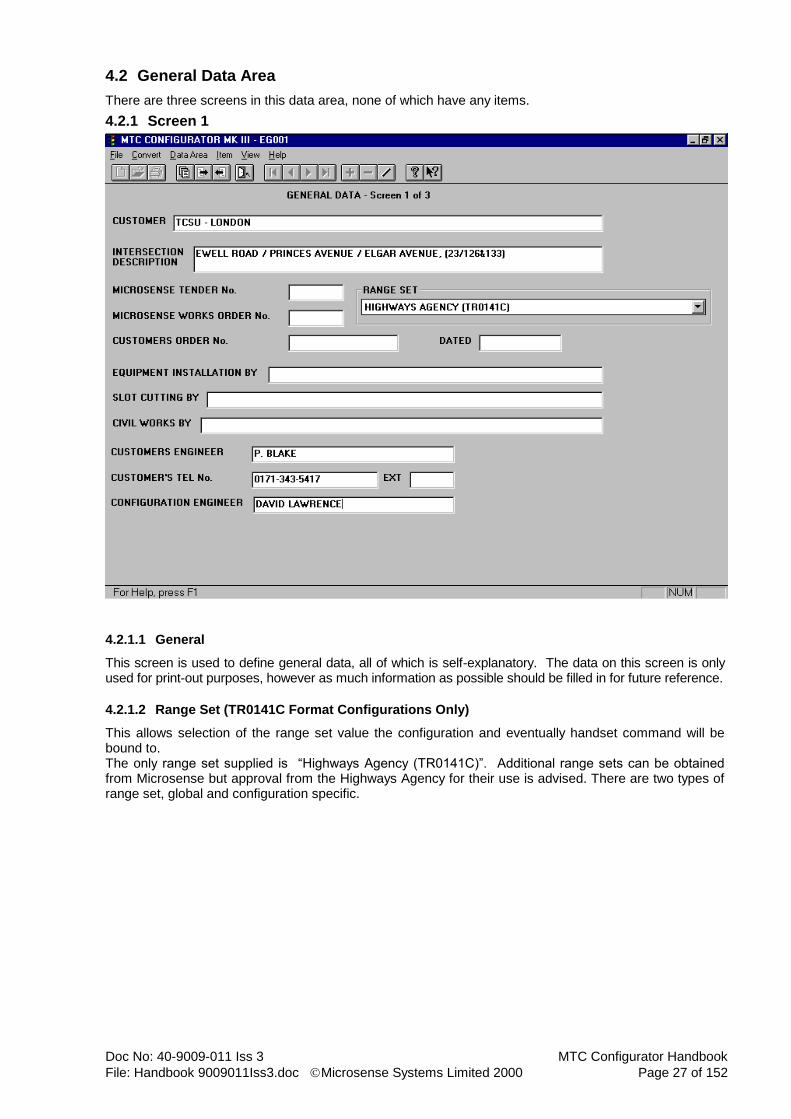
4.2.1 Screen 1
4.2.1.1 General
This screen is used to define general data, all of which is self-explanatory. The data on this screen is only used for print-out purposes, however as much information as possible should be filled in for future reference.
4.2.1.2 Range Set (TR0141C Format Configurations Only)
This allows selection of the range set value the configuration and eventually handset command will be bound to. The only range set supplied is “Highways Agency (TR0141C)”. Additional range sets can be obtained from Microsense but approval from the Highways Agency for their use is advised. There are two types of range set, global and configuration specific.

MTC Configurator Handbook Doc No: 40-9009-011 Iss 3
Page 28 of 152 Microsense Systems Limited 2000 File: Handbook 9009011Iss3.doc
4.2.2 Screen 2
4.2.2.1 General
This screen is used to define more general data. The data on this screen is a combination of data only used for print-out purposes and data used in the PROM.
4.2.2.2 Mains Voltage
May be either 220 or 240 volts, (default is 240). This data is for print-out purposes only.
4.2.2.3 Mains Frequency
May only be 50 Hz at the present time. This data is for print-out purposes only.
4.2.2.4 Peak Current
Must be in the range 0 to 30 amps. This data is for print-out purposes only.
4.2.2.5 BST Start/End Week
For British Summer Time changes note that on the MTC a week begins on Monday, week 1 is the first week containing 4 or more days in January and changeover takes place at 2am on Sunday morning. To disable this facility enter both week numbers as 0. Default week numbers are 13 and 43 respectively.
4.2.2.6 Lamp Sequence Flash On/Off Duration
Must be in the range of 0 to 5 seconds in 0.1 second steps. The default values are 0.4 seconds for both and these values should not be changed for UK use.
4.2.2.7 Manual Disable Via Handset Option Required
This facility is selected/deselected by the adjacent check box.

Doc No: 40-9009-011 Iss 3 MTC Configurator Handbook
File: Handbook 9009011Iss3.doc Microsense Systems Limited 2000 Page 29 of 152
4.2.2.8 Dimming Voltage
If dimming is required the voltage may be 160, 140 or 120 volts. The selected option is indicated by the adjacent radio button. This data is for print-out purposes only.
4.2.2.9 Solar Switch Data
Call/cancel delay times are used to provide a filter period and must be in the range of 10 to 300 seconds in 0.1 second steps. Default values are all 60 seconds. DFM times must be in the range of 0 to 15300 minutes in steps of 1 minute, or 0 to 255 hours in steps of 1 hour. Note that minute values must be suffixed with M and hour values with H. If dimming is not required then all DFM timings must be entered as 0H. Default values are all 18 hours. The four alternative timings form part of the detector timing set which may be changed via the timetable.
4.2.2.10 Level 3 Access (TR0141C Format Configurations Only)
Password is case sensitive and must be between four and eight characters long. The default password is “MSNS”; upper case was used, as some handset do not support lower case. Period is the time allowed by the controller between command entries. If the input is inactive for longer than this, level 3 access is denied. This period must be between 60 and 3600 seconds in step of 1 second. (Note that if the handset is disconnected, level 3 access will be lost.)
MTC Configurator Handbook Doc No: 40-9009-011 Iss 3
Page 30 of 152 Microsense Systems Limited 2000 File: Handbook 9009011Iss3.doc
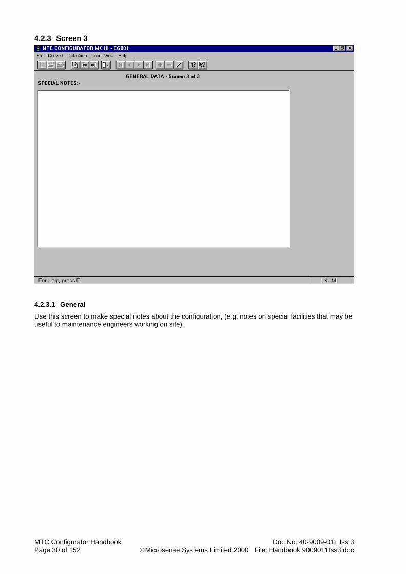
4.2.3 Screen 3
4.2.3.1 General
Use this screen to make special notes about the configuration, (e.g. notes on special facilities that may be useful to maintenance engineers working on site).
Doc No: 40-9009-011 Iss 3 MTC Configurator Handbook
File: Handbook 9009011Iss3.doc Microsense Systems Limited 2000 Page 31 of 152
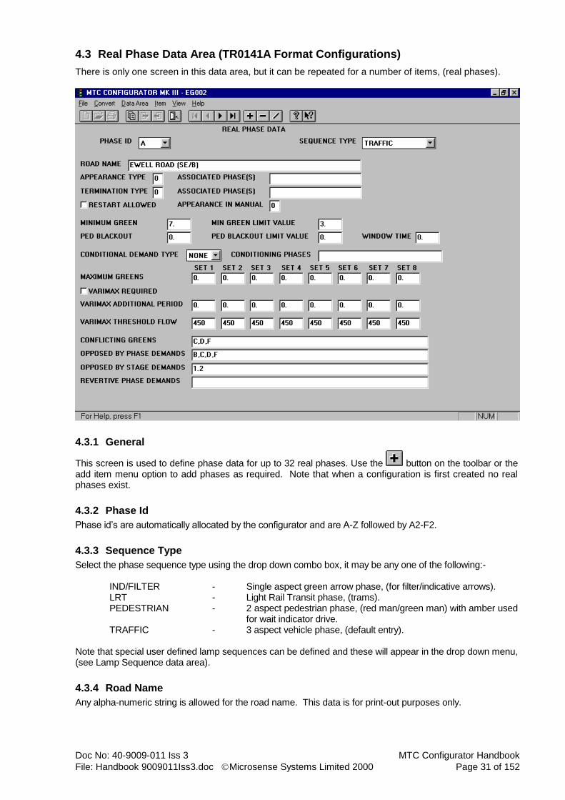
4.3 Real Phase Data Area (TR0141A Format Configurations)
There is only one screen in this data area, but it can be repeated for a number of items, (real phases).
4.3.1 General
This screen is used to define phase data for up to 32 real phases. Use the button on the toolbar or the add item menu option to add phases as required. Note that when a configuration is first created no real phases exist.
4.3.2 Phase Id
Phase id’s are automatically allocated by the configurator and are A-Z followed by A2-F2.
4.3.3 Sequence Type
Select the phase sequence type using the drop down combo box, it may be any one of the following:- IND/FILTER - Single aspect green arrow phase, (for filter/indicative arrows). LRT - Light Rail Transit phase, (trams). PEDESTRIAN - 2 aspect pedestrian phase, (red man/green man) with amber used
for wait indicator drive. TRAFFIC - 3 aspect vehicle phase, (default entry). Note that special user defined lamp sequences can be defined and these will appear in the drop down menu, (see Lamp Sequence data area).
4.3.4 Road Name
Any alpha-numeric string is allowed for the road name. This data is for print-out purposes only.
MTC Configurator Handbook Doc No: 40-9009-011 Iss 3
Page 32 of 152 Microsense Systems Limited 2000 File: Handbook 9009011Iss3.doc
4.3.5 Appearance Type
Phase appearance type may be any one of the following :- TYPE MEANING 0 - Phase always appears when stage runs, (default value). 1 - Phase appears only if demand exists at start of stage*, or as type 2 if no opposing demands exist against the phase. 2 - Phase appears, if demanded, at any time up until the end of the stage. 3 - Phase appears, if demanded, at any time during the stage up until the window time expires, or after the window if no opposing demands exist for the phase. 4 - Phase appears when one of its associated phases runs. * Where a type 1 phase can appear in several consecutive stages this relates only to the start of the first stage. Note that only appearance type 4 requires an associated phase(s) to be specified. For all other types it should be left blank.
4.3.6 Termination Type
Phase termination type may be any one of the following :- TYPE MEANING 0 - Phase terminates at end of stage, (default value). 1 - Phase terminates when associated phase gains right-of-way. 2 - Phase terminates when associated phase loses right-of-way. 3 - Phase terminates when minimum green expires. 4 - Phase can terminate early when its maximum green expires. 5 - Phase terminates early on gap condition or when its maximum green expires. Note that only termination types 1 or 2 require an associated phase(s) to be specified. For all other types it should be left blank.
4.3.7 Restart Allowed
Restart allowed is only applicable for phases with an appearance type of 1, 2, 3 or 4 and a termination type of 3, 4 or 5. This facility allows a phase to be restarted if it has previously terminated early, (subject to its normal starting conditions) and is selected/deselected by the adjacent check box.
4.3.8 Appearance In Manual
Phase appearance in manual mode may be any one of the following :- TYPE MEANING 0 - Phase always appears during manual mode, (default value). 1 - Phase never appears during manual mode. 2 - Phase is demand dependant during manual mode. Note that this facility is only applicable for demand dependant phases, (i.e. with appearance types 1, 2, 3 or 4).

Doc No: 40-9009-011 Iss 3 MTC Configurator Handbook
File: Handbook 9009011Iss3.doc Microsense Systems Limited 2000 Page 33 of 152
4.3.9 Minimum Green
Phase minimum green time must be in the range of 0 to 300 seconds in 0.1 second steps. Default value is 7 seconds.
4.3.10 Min Green Limit Value
Phase minimum green limit value must be in the range of 0 to 300 seconds in 0.1 second steps. Default value is 3 seconds.
4.3.11 Ped Blackout
Pedestrian blackout time must be in the range of 0 to 300 seconds in 0.1 second steps.
4.3.12 Ped Blackout Limit Value
Pedestrian blackout limit value must be in the range of 0 to 300 seconds in 0.1 second steps.
4.3.13 Window Time
Phase window time, (only for type 3 appearance phases) must be in the range of 0 to 300 seconds in 0.1 second steps.
4.3.14 Conditional Demand Type
Conditional demand type is selected using the drop down combo box and can be NONE, ANY or ALL. For types of ANY and ALL a conditioning phase(s) must be specified. The default entry is NONE. This facility blocks demands for the phase unless ANY or ALL of the conditioning phases are demanded as well.
4.3.15 Conditioning Phases
Conditioning phases need only be specified if the conditional demand type ANY or ALL. Note that multiple phase id’s must be separated by commas. Real or dummy phases may be specified.
4.3.16 Maximum Greens
Phase maximum green times should be specified, as required, for extendible phases and must be in the range of 0 to 300 seconds in 0.1 steps. The 8 alternative timings available form part of the phase timing set which may be changed via the timetable.
4.3.17 Varimax Required
The variable maximum facility is selected/deselected by the adjacent check box.
4.3.18 Varimax Additional Period
Varimax additional periods should be specified, as required, for extendible phases using the varimax facility and must be in the range of 0 to 100 seconds in 0.1 second steps. The 8 values available for varimax form part of the phase timing set which may be changed via the timetable.
4.3.19 Varimax Threshold Flow
Varimax threshold flow values should be specified, as required, for extendible phases using the varimax facility and must be in the range of 450 to 3000 vph in steps of 1 vph. The 8 values available for varimax form part of the phase timing set which may be changed via the timetable. Default values are all 450 vph.

MTC Configurator Handbook Doc No: 40-9009-011 Iss 3
Page 34 of 152 Microsense Systems Limited 2000 File: Handbook 9009011Iss3.doc
4.3.20 Conflicting Greens
For conflicting greens, list all of the real phases and switched signs with security that conflict with this phase, (dummy phases cannot conflict). Switched signs with security are indicated by the id of the phase drive that they are allocated to. Note that multiple phase id’s must be separated by commas. ALL is allowed as a valid entry in this field, where it means all phases in the current stage stream except the current phase. ALL may optionally be followed by an exceptions list (e.g. ALL, C, D means all phases in the current stage stream except the current phase and phases C and D).
4.3.21 Opposed By Phase Demands
For opposed by phase demands, list all of the phases, (real & dummy) that oppose this phase, (i.e. phases whose demands should start the maximum green timer of this phase). A phase should normally be opposed by all other phases in the same stream. Note that multiple phase id’s must be separated by commas. ALL is allowed as a valid entry in this field, where it means all phases in the current stage stream except the current phase. ALL may optionally be followed by an exceptions list (e.g. ALL, C, D means all phases in the current stage stream except the current phase and phases C and D).
4.3.22 Opposed By Stage Demands
For opposed by stage demands, list all of the stages that oppose this phase, (i.e. stages whose demands should start the maximum green timer of this phase). This only needs to be filled in if stage demands are being used either from UTC demand bits or from special conditioning, otherwise it can be left blank. A stage must be indicated in ‘stream.stage’ format, (e.g. 1.2 = stream 1, stage 2). Note that multiple stage id’s must be separated by commas.
4.3.23 Revertive Phase Demands
For revertive phase demands enter the phase(s) to be demanded if this phase terminates with extensions active. An extendible traffic phase usually inserts a revertive demand for itself and an indicative green arrow phase usually inserts one for its associated, (full green) phase. Non-extendible phases, (e.g. pedestrians, filter green arrows, etc) do not require an entry. Note that multiple phase id’s must be separated by commas. Real or dummy phases may be specified.

Doc No: 40-9009-011 Iss 3 MTC Configurator Handbook
File: Handbook 9009011Iss3.doc Microsense Systems Limited 2000 Page 35 of 152
4.4 Real Phase Data Area (TR0141C Format Configurations)
There two screen in this data area and they can be repeated for a number of items, (real phases).
4.4.1 Screen 1
4.4.1.1 General
This screen is used to define phase data for up to 32 real phases. Use the button on the toolbar or the add item menu option to add phases as required. Note that when a configuration is first created no real phases exist.
4.4.1.2 Phase Id
Phase id’s are automatically allocated by the configurator and are A-Z followed by A2-F2.
4.4.1.3 Road Name
Any alpha-numeric string is allowed for the road name. This data is for print-out purposes only.
MTC Configurator Handbook Doc No: 40-9009-011 Iss 3
Page 36 of 152 Microsense Systems Limited 2000 File: Handbook 9009011Iss3.doc
4.4.1.4 Sequence Type
Select the phase sequence type using the drop down combo box, it may be any one of the following:-
FAR-SIDE PEDESTRIAN - 2 aspect pedestrian phase, (red man/green man) with amber used for wait lamp. Where the red/green man signal is on the opposite side of the road to the push button box. (Traditional style.)
IND/FILTER - Single aspect green arrow phase, (for filter/indicative arrows). LRT - Light Rail Transit phase, (trams). NEAR-SIDE PEDESTRIAN - 2 aspect pedestrian phase, (red man/green man) with amber used for
wait lamp. Where the red/green man signal is on the same side of the road to the push button box.
PEDESTRIAN - 2 aspect pedestrian phase, (red man/green man) with amber used for wait lamp. Where the red/green man signal is on the opposite side of the road to the push button box.
PELICAN PEDESTRIAN - 2 aspect pedestrian phase, (red man/green man) with amber used for wait lamp. (Uses flashing green man aspect).
PELICAN TRAFFIC - 3 aspect vehicle phase, (uses flashing amber aspect). TRAFFIC - 3 aspect vehicle phase, (default entry).
Note that special user defined lamp sequences can be defined and these will appear in the drop down menu, (see Lamp Sequence data area).
4.4.1.5 Appearance Type
Phase appearance type may be any one of the following :- TYPE MEANING
0 - Phase always appears when stage runs, (default value). 1 - Phase appears only if demand exists at start of stage*, or as type 2 if no opposing
demands exist against the phase. 2 - Phase appears, if demanded, at any time up until the end of the stage. 3 - Phase appears, if demanded, at any time during the stage up until the window time
expires, or after the window if no opposing demands exist for the phase. 4 - Phase appears when one of its associated phases runs.
* Where a type 1 phase can appear in several consecutive stages this relates only to the start of the first stage. Note that only appearance type 4 requires an associated phase(s) to be specified. For all other types it should be left blank.
4.4.1.6 Termination Type
Phase termination type may be any one of the following :- TYPE MEANING 0 - Phase terminates at end of stage, (default value). 1 - Phase terminates when associated phase gains right-of-way. 2 - Phase terminates when associated phase loses right-of-way. 3 - Phase terminates when minimum green expires. 4 - Phase can terminate early when its maximum green expires. 5 - Phase terminates early on gap condition or when its maximum green expires. Note that only termination types 1 or 2 require an associated phase(s) to be specified. For all other types it should be left blank.
Doc No: 40-9009-011 Iss 3 MTC Configurator Handbook
File: Handbook 9009011Iss3.doc Microsense Systems Limited 2000 Page 37 of 152
4.4.1.7 Restart Allowed
Restart allowed is only applicable for phases with an appearance type of 1, 2, 3 or 4 and a termination type of 3, 4 or 5. This facility allows a phase to be restarted if it has previously terminated early, (subject to its normal starting conditions) and is selected/deselected by the adjacent check box.
4.4.1.8 Appearance In Manual
Phase appearance in manual mode may be any one of the following :- TYPE MEANING 0 - Phase always appears during manual mode, (default value). 1 - Phase never appears during manual mode. 2 - Phase is demand dependant during manual mode. Note that this facility is only applicable for demand dependant phases, (i.e. with appearance types 1, 2, 3 or 4).
4.4.1.9 Minimum Green
The range of valid phase minimum green time is now dependant on the lamp sequence type, stream type and whether in the case of a vehicle phase it is associated to a pedestrian phase. (The following ranges are quoted ranges are in 0.1 second steps). Default value is 7 seconds.
0 to 30 seconds for vehicle phases not associated with a crossing. 6 to 15 seconds for vehicle phases at a stand-alone crossing. 3 to 15 seconds for vehicle phases associated with a pedestrian phase, at a junction. 4 to 9 seconds for pedestrian phases at a stand-alone crossing. 4 to 99 seconds for pedestrian phases at a junction.
4.4.1.10 Min Green Limit Value
Phase minimum green limit value must be in the range of 0 to the upper limit of the minimum green seconds in 0.1 second steps. Default value is 3 seconds. Note under TR0141C only dummy phases and left-hand filter arrows can be set to have a minimum green limit of below 3 seconds.
4.4.1.11 Window Time
Phase window time, (only for type 3 appearance phases) must be in the range of 0 to 300 seconds in 0.1 second steps.
4.4.1.12 Conditional Demand Type
Conditional demand type is selected using the drop down combo box and can be NONE, ANY or ALL. For types of ANY and ALL a conditioning phase(s) must be specified. The default entry is NONE. This facility blocks demands for the phase unless ANY or ALL of the conditioning phases are demanded as well.
4.4.1.13 Conditioning Phases
Conditioning phases need only be specified if the conditional demand type ANY or ALL. Note that multiple phase id’s must be separated by commas. Real or dummy phases may be specified.
4.4.1.14 Conflicting Greens
For conflicting greens, list all of the real phases and switched signs with security that conflict with this phase, (dummy phases cannot conflict). Switched signs with security are indicated by the id of the phase drive that they are allocated to. Note that multiple phase id’s must be separated by commas. ALL is allowed as a valid entry in this field, where it means all phases in the current stage stream except the current phase. ALL may optionally be followed by an exceptions list (e.g. ALL, C, D means all phases in the current stage stream except the current phase and phases C and D).
4.4.1.15 Opposed By Phase Demands
For opposed by phase demands, list all of the phases, (real & dummy) that oppose this phase, (i.e. phases whose demands should start the maximum green timer of this phase). A phase should normally be opposed

MTC Configurator Handbook Doc No: 40-9009-011 Iss 3
Page 38 of 152 Microsense Systems Limited 2000 File: Handbook 9009011Iss3.doc
by all other phases in the same stream. Note that multiple phase id’s must be separated by commas. ALL is allowed as a valid entry in this field, where it means all phases in the current stage stream except the current phase. ALL may optionally be followed by an exceptions list (e.g. ALL, C, D means all phases in the current stage stream except the current phase and phases C and D).
4.4.1.16 Opposed By Stage Demands
For opposed by stage demands, list all of the stages that oppose this phase, (i.e. stages whose demands should start the maximum green timer of this phase). This only needs to be filled in if stage demands are being used either from UTC demand bits or from special conditioning, otherwise it can be left blank. A stage must be indicated in ‘stream.stage’ format, (e.g. 1.2 = stream 1, stage 2). Note that multiple stage id’s must be separated by commas.
4.4.1.17 Revertive Phase Demands
For revertive phase demands enter the phase(s) to be demanded if this phase terminates with extensions active. An extendible traffic phase usually inserts a revertive demand for itself and an indicative green arrow phase usually inserts one for its associated, (full green) phase. Non-extendible phases, (e.g. pedestrians, filter green arrows, etc) do not require an entry. Note that multiple phase id’s must be separated by commas. Real or dummy phases may be specified.

Doc No: 40-9009-011 Iss 3 MTC Configurator Handbook
File: Handbook 9009011Iss3.doc Microsense Systems Limited 2000 Page 39 of 152
4.4.2 Screen 2 (Traffic Sequence)
4.4.2.1 General
This screen is only seen if a vehicle lamp sequence was selected on screen 1. The sequence type selected on Screen 1 is shown for reference.
4.4.2.2 Phase Id
Phase id’s are automatically allocated by the configurator and are A-Z followed by A2-F2.
4.4.2.3 Associated To Pedestrian Phases
The adjacent check box is used to select/deselect whether the current phase is associated to pedestrian phases.
4.4.2.4 Allowed Modes
Selection of the allowed modes of the vehicle phase is only available with the selection of associated to pedestrian phases. Three modes of operation are available vehicle actuated [VA], pre-timed maximum [PTM] and fixed vehicle period [FVP]; at least one of these must be selected.
4.4.2.5 Default Mode
Default mode is only applicable for phases that are associated to pedestrian phase and therefore could support other modes besides VA.
4.4.2.6 Speed Measurement Facilities
The speed measurement facilities are selected/deselected by the adjacent check box.

MTC Configurator Handbook Doc No: 40-9009-011 Iss 3
Page 40 of 152 Microsense Systems Limited 2000 File: Handbook 9009011Iss3.doc
4.4.2.7 Pedestrian Phases Which Cross This Phase
Pedestrian phases which cross this phase, is only applicable with speed measurement facilities, list all the pedestrian phases that cross this phase.
4.4.2.8 Maximum Greens
Phase maximum green times should be specified, as required, for extendible phases and must be in the ranges to follow; each range is in 0.1 steps.
0 to 99 seconds for VA maximum greens for phases not associated with pedestrian phases. 10 to 60 seconds for VA maximum greens for phases associated with pedestrian phases. 10 to 60 seconds for PTM maximum greens.
20 to 60 seconds for FVP maximum greens. The 8 alternative timings available form part of the phase timing set which may be changed via the timetable for each available mode of operation.
4.4.2.9 Varimax Required
The variable maximum facility is selected/deselected by the adjacent check box.
4.4.2.10 Varimax Additional Period
Varimax additional periods should be specified, as required, for extendible phases using the varimax facility and must be in the range of 0 to 100 seconds in 0.1 second steps. The 8 values available for varimax form part of the phase timing set which may be changed via the timetable.
4.4.2.11 Varimax Threshold Flow
Varimax threshold flow values should be specified, as required, for extendible phases using the varimax facility and must be in the range of 900 to 3000 vph in steps of 1 vph. The 8 values available for varimax form part of the phase timing set which may be changed via the timetable. Default values are all 450 vph.

Doc No: 40-9009-011 Iss 3 MTC Configurator Handbook
File: Handbook 9009011Iss3.doc Microsense Systems Limited 2000 Page 41 of 152
4.4.3 Screen 2 (Pedestrian Sequence)
4.4.3.1 General
This screen is only seen if a pedestrian lamp sequence was selected on screen 1. The sequence type selected on Screen 1 is shown for reference.
4.4.3.2 Phase Id
Phase id’s are automatically allocated by the configurator and are A-Z followed by A2-F2.
4.4.3.3 Fixed Sequence
Fixed sequence can be selected/deselected as required by the adjacent check box for all pedestrian phases excluding pelican phases.
4.4.3.4 Toucan (if checked else) Puffin
Toucan can be selected instead of Puffin as required by selecting the adjacent check box. Note this can not be specified for fixed sequence or pelican phases.
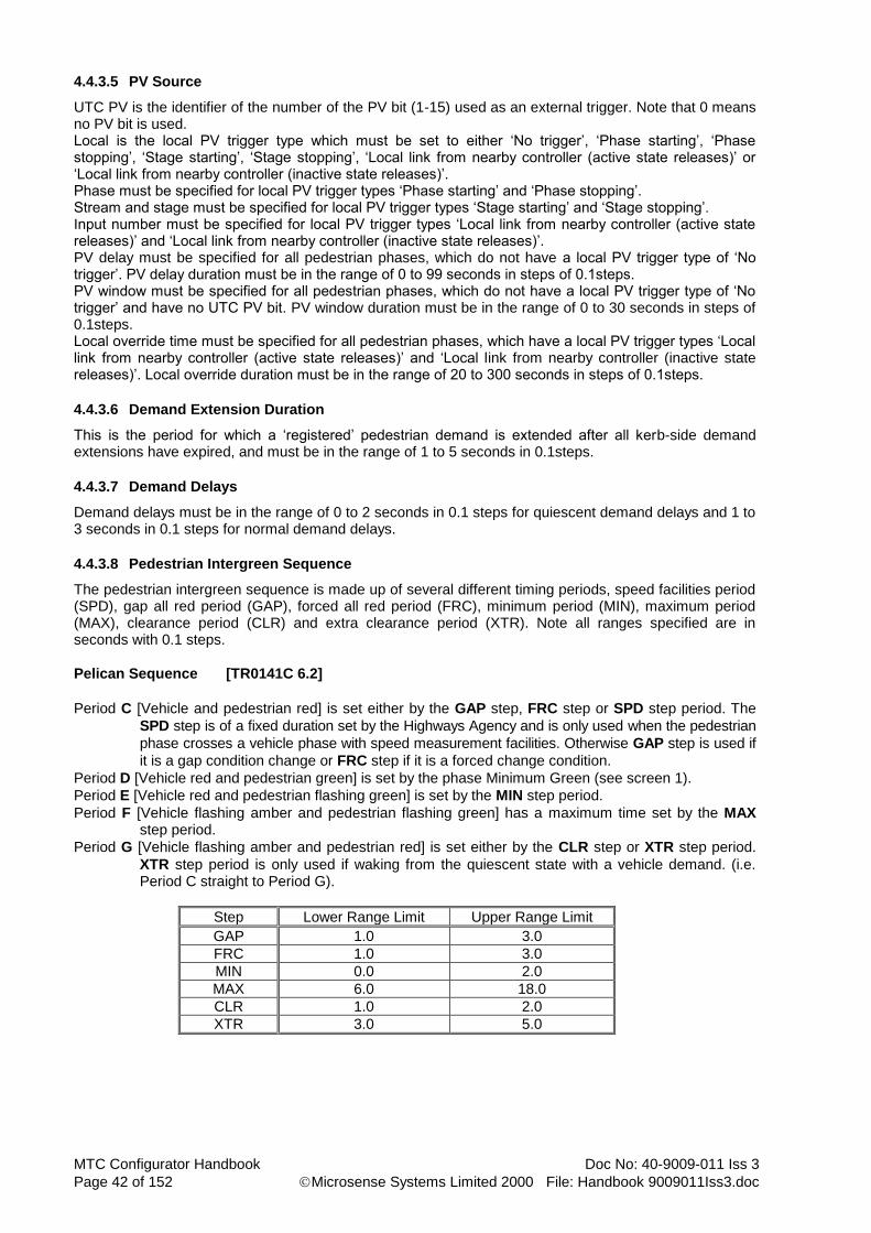
MTC Configurator Handbook Doc No: 40-9009-011 Iss 3
Page 42 of 152 Microsense Systems Limited 2000 File: Handbook 9009011Iss3.doc
4.4.3.5 PV Source
UTC PV is the identifier of the number of the PV bit (1-15) used as an external trigger. Note that 0 means no PV bit is used. Local is the local PV trigger type which must be set to either ‘No trigger’, ‘Phase starting’, ‘Phase stopping’, ‘Stage starting’, ‘Stage stopping’, ‘Local link from nearby controller (active state releases)’ or ‘Local link from nearby controller (inactive state releases)’. Phase must be specified for local PV trigger types ‘Phase starting’ and ‘Phase stopping’. Stream and stage must be specified for local PV trigger types ‘Stage starting’ and ‘Stage stopping’. Input number must be specified for local PV trigger types ‘Local link from nearby controller (active state releases)’ and ‘Local link from nearby controller (inactive state releases)’. PV delay must be specified for all pedestrian phases, which do not have a local PV trigger type of ‘No trigger’. PV delay duration must be in the range of 0 to 99 seconds in steps of 0.1steps. PV window must be specified for all pedestrian phases, which do not have a local PV trigger type of ‘No trigger’ and have no UTC PV bit. PV window duration must be in the range of 0 to 30 seconds in steps of 0.1steps. Local override time must be specified for all pedestrian phases, which have a local PV trigger types ‘Local link from nearby controller (active state releases)’ and ‘Local link from nearby controller (inactive state releases)’. Local override duration must be in the range of 20 to 300 seconds in steps of 0.1steps.
4.4.3.6 Demand Extension Duration
This is the period for which a ‘registered’ pedestrian demand is extended after all kerb-side demand extensions have expired, and must be in the range of 1 to 5 seconds in 0.1steps.
4.4.3.7 Demand Delays
Demand delays must be in the range of 0 to 2 seconds in 0.1 steps for quiescent demand delays and 1 to 3 seconds in 0.1 steps for normal demand delays.
4.4.3.8 Pedestrian Intergreen Sequence
The pedestrian intergreen sequence is made up of several different timing periods, speed facilities period (SPD), gap all red period (GAP), forced all red period (FRC), minimum period (MIN), maximum period (MAX), clearance period (CLR) and extra clearance period (XTR). Note all ranges specified are in seconds with 0.1 steps.
Pelican Sequence [TR0141C 6.2]
Period C [Vehicle and pedestrian red] is set either by the GAP step, FRC step or SPD step period. The
SPD step is of a fixed duration set by the Highways Agency and is only used when the pedestrian
phase crosses a vehicle phase with speed measurement facilities. Otherwise GAP step is used if
it is a gap condition change or FRC step if it is a forced change condition.
Period D [Vehicle red and pedestrian green] is set by the phase Minimum Green (see screen 1).
Period E [Vehicle red and pedestrian flashing green] is set by the MIN step period.
Period F [Vehicle flashing amber and pedestrian flashing green] has a maximum time set by the MAX step period.
Period G [Vehicle flashing amber and pedestrian red] is set either by the CLR step or XTR step period.
XTR step period is only used if waking from the quiescent state with a vehicle demand. (i.e. Period C straight to Period G).
Step Lower Range Limit Upper Range Limit
GAP 1.0 3.0
FRC 1.0 3.0
MIN 0.0 2.0
MAX 6.0 18.0
CLR 1.0 2.0
XTR 3.0 5.0
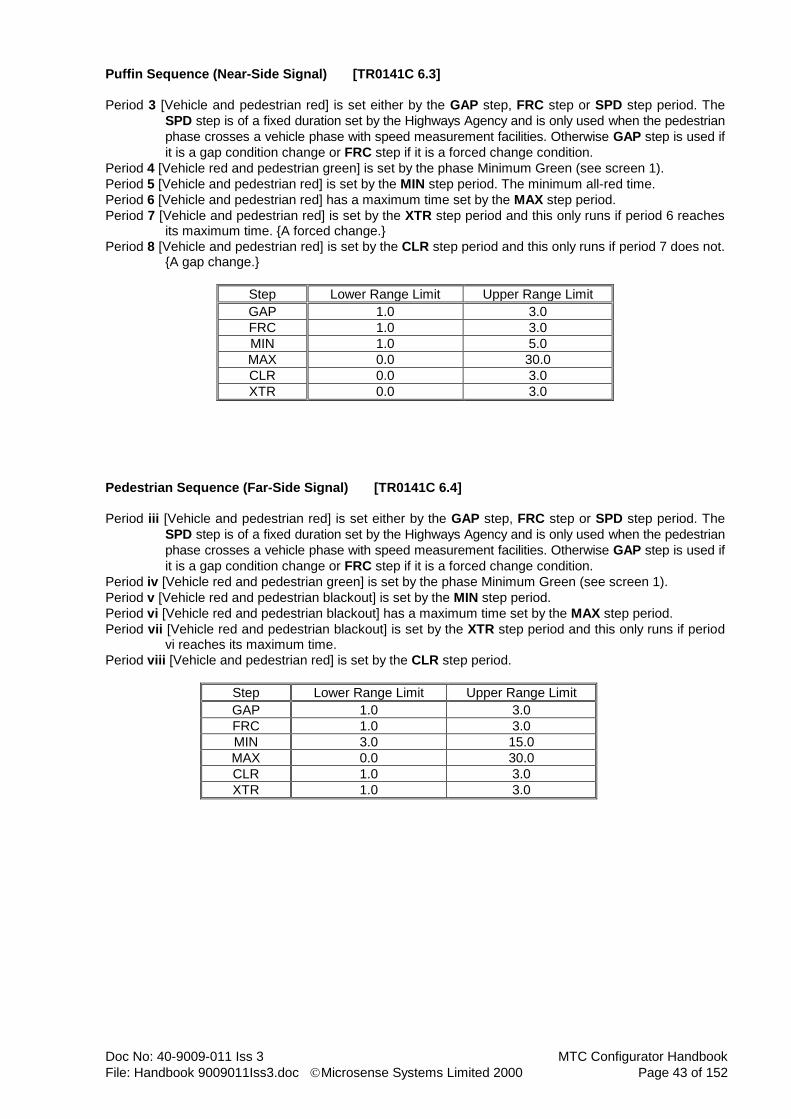
Doc No: 40-9009-011 Iss 3 MTC Configurator Handbook
File: Handbook 9009011Iss3.doc Microsense Systems Limited 2000 Page 43 of 152
Puffin Sequence (Near-Side Signal) [TR0141C 6.3]
Period 3 [Vehicle and pedestrian red] is set either by the GAP step, FRC step or SPD step period. The
SPD step is of a fixed duration set by the Highways Agency and is only used when the pedestrian
phase crosses a vehicle phase with speed measurement facilities. Otherwise GAP step is used if
it is a gap condition change or FRC step if it is a forced change condition.
Period 4 [Vehicle red and pedestrian green] is set by the phase Minimum Green (see screen 1).
Period 5 [Vehicle and pedestrian red] is set by the MIN step period. The minimum all-red time.
Period 6 [Vehicle and pedestrian red] has a maximum time set by the MAX step period.
Period 7 [Vehicle and pedestrian red] is set by the XTR step period and this only runs if period 6 reaches its maximum time. {A forced change.}
Period 8 [Vehicle and pedestrian red] is set by the CLR step period and this only runs if period 7 does not. {A gap change.}
Step Lower Range Limit Upper Range Limit
GAP 1.0 3.0
FRC 1.0 3.0
MIN 1.0 5.0
MAX 0.0 30.0
CLR 0.0 3.0
XTR 0.0 3.0
Pedestrian Sequence (Far-Side Signal) [TR0141C 6.4]
Period iii [Vehicle and pedestrian red] is set either by the GAP step, FRC step or SPD step period. The
SPD step is of a fixed duration set by the Highways Agency and is only used when the pedestrian
phase crosses a vehicle phase with speed measurement facilities. Otherwise GAP step is used if
it is a gap condition change or FRC step if it is a forced change condition.
Period iv [Vehicle red and pedestrian green] is set by the phase Minimum Green (see screen 1).
Period v [Vehicle red and pedestrian blackout] is set by the MIN step period.
Period vi [Vehicle red and pedestrian blackout] has a maximum time set by the MAX step period.
Period vii [Vehicle red and pedestrian blackout] is set by the XTR step period and this only runs if period vi reaches its maximum time.
Period viii [Vehicle and pedestrian red] is set by the CLR step period.
Step Lower Range Limit Upper Range Limit
GAP 1.0 3.0
FRC 1.0 3.0
MIN 3.0 15.0
MAX 0.0 30.0
CLR 1.0 3.0
XTR 1.0 3.0
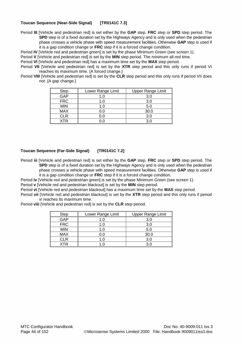
MTC Configurator Handbook Doc No: 40-9009-011 Iss 3
Page 44 of 152 Microsense Systems Limited 2000 File: Handbook 9009011Iss3.doc
Toucan Sequence (Near-Side Signal) [TR0141C 7.3]
Period III [Vehicle and pedestrian red] is set either by the GAP step, FRC step or SPD step period. The
SPD step is of a fixed duration set by the Highways Agency and is only used when the pedestrian
phase crosses a vehicle phase with speed measurement facilities. Otherwise GAP step is used if
it is a gap condition change or FRC step if it is a forced change condition.
Period IV [Vehicle red and pedestrian green] is set by the phase Minimum Green (see screen 1).
Period V [Vehicle and pedestrian red] is set by the MIN step period. The minimum all-red time.
Period VI [Vehicle and pedestrian red] has a maximum time set by the MAX step period.
Period VII [Vehicle and pedestrian red] is set by the XTR step period and this only runs if period VI reaches its maximum time. {A forced change.}
Period VIII [Vehicle and pedestrian red] is set by the CLR step period and this only runs if period VII does not. {A gap change.}
Step Lower Range Limit Upper Range Limit
GAP 1.0 3.0
FRC 1.0 3.0
MIN 1.0 5.0
MAX 0.0 30.0
CLR 0.0 3.0
XTR 0.0 3.0
Toucan Sequence (Far-Side Signal) [TR0141C 7.2]
Period iii [Vehicle and pedestrian red] is set either by the GAP step, FRC step or SPD step period. The
SPD step is of a fixed duration set by the Highways Agency and is only used when the pedestrian
phase crosses a vehicle phase with speed measurement facilities. Otherwise GAP step is used if
it is a gap condition change or FRC step if it is a forced change condition.
Period iv [Vehicle red and pedestrian green] is set by the phase Minimum Green (see screen 1).
Period v [Vehicle red and pedestrian blackout] is set by the MIN step period.
Period vi [Vehicle red and pedestrian blackout] has a maximum time set by the MAX step period.
Period vii [Vehicle red and pedestrian blackout] is set by the XTR step period and this only runs if period vi reaches its maximum time.
Period viii [Vehicle and pedestrian red] is set by the CLR step period.
Step Lower Range Limit Upper Range Limit
GAP 1.0 3.0
FRC 1.0 3.0
MIN 1.0 5.0
MAX 0.0 30.0
CLR 1.0 3.0
XTR 1.0 3.0

Doc No: 40-9009-011 Iss 3 MTC Configurator Handbook
File: Handbook 9009011Iss3.doc Microsense Systems Limited 2000 Page 45 of 152
Fixed Sequence (Near-Side Signal) [TR0141C 6.3 & 7.3]
Period 3, III [Vehicle and pedestrian red] is set either by the GAP step, FRC step or SPD step period. The
SPD step is of a fixed duration set by the Highways Agency and is only used when the pedestrian
phase crosses a vehicle phase with speed measurement facilities. Otherwise GAP step is used if
it is a gap condition change or FRC step if it is a forced change condition.
Period 4, IV [Vehicle red and pedestrian green] is set by the phase Minimum Green (see screen 1).
Period 5, V [Vehicle and pedestrian red] is set by the MIN step period.
Period 6, VI is not applicable.
Period 7, VII is not applicable.
Period 8, VIII [Vehicle and pedestrian red] is set by the CLR step period.
Step Lower Range Limit Upper Range Limit
GAP 1.0 3.0
FRC 1.0 3.0
MIN 1.0 * 45.0 *
MAX N/A N/A
CLR 1.0 3.0
XTR N/A N/A
* - This is an overall range. Refer to TR0141C for the specific fixed sequence (near-side) range that is
required.
Fixed Sequence (Far-Side Signal) [TR0141C 6.4 & 7.2]
Period iii [Vehicle and pedestrian red] is set either by the GAP step, FRC step or SPD step period. The
SPD step is of a fixed duration set by the Highways Agency and is only used when the pedestrian
phase crosses a vehicle phase with speed measurement facilities. Otherwise GAP step is used if
it is a gap condition change or FRC step if it is a forced change condition.
Period iv [Vehicle red and pedestrian green] is set by the phase Minimum Green (see screen 1).
Period v [Vehicle red and pedestrian blackout] is set by the MIN period.
Period vi is not applicable.
Period vii is not applicable.
Period viii [Vehicle and pedestrian red] is set by the CLR period.
Step Lower Range Limit Upper Range Limit
GAP 1.0 3.0
FRC 1.0 3.0
MIN 1.0 * 45.0 *
MAX N/A N/A
CLR 1.0 3.0
XTR N/A N/A
* - This is an overall range. Refer to TR0141C for the specific fixed sequence (far-side) range that is
required.

MTC Configurator Handbook Doc No: 40-9009-011 Iss 3
Page 46 of 152 Microsense Systems Limited 2000 File: Handbook 9009011Iss3.doc
4.5 Dummy Phase Data Area (TR0141A Format Configurations)
There is only one screen in this data area, but it can be repeated for a number of items, (dummy phases).
4.5.1 General
This screen is used to define phase data for up to 26 dummy phases. Use the button on the toolbar or the add item menu option to add phases as required. For all fields other than the following refer to the description given for real phases in the previous data area. Note that when a configuration is first created no dummy phases exist.
4.5.2 Phase Id/Dummy Name
Phase id’s are automatically allocated by the configurator and are DA-DZ. However, by using the dummy name field you can alter the id of a dummy phase, but care must be taken not to use an id that the Configurator may allocate when adding subsequent phases.

Doc No: 40-9009-011 Iss 3 MTC Configurator Handbook
File: Handbook 9009011Iss3.doc Microsense Systems Limited 2000 Page 47 of 152
4.6 Dummy Phase Data Area (TR0141C Format Configurations)
There two screen in this data area and they can be repeated for a number of items, (dummy phases).
4.6.1 Screen 1
4.6.1.1 General
This screen is used to define phase data for up to 26 dummy phases. Use the button on the toolbar or the add item menu option to add phases as required. For all fields other than the following refer to the description given for real phases in the previous data area. Note that when a configuration is first created no dummy phases exist.
4.6.1.2 Phase Id/Dummy Name
Phase id’s are automatically allocated by the configurator and are DA-DZ. However, by using the dummy name field you can alter the id of a dummy phase, but care must be taken not to use an id that the Configurator may allocate when adding subsequent phases.

MTC Configurator Handbook Doc No: 40-9009-011 Iss 3
Page 48 of 152 Microsense Systems Limited 2000 File: Handbook 9009011Iss3.doc
4.6.2 Screen 2 (Traffic Sequence)
4.6.2.1 General
This screen is used to define phase data for up to 26 dummy phases. Use the button on the toolbar or the add item menu option to add phases as required. For all fields other than the following refer to the description given for real phases in the previous data area. Note that when a configuration is first created no dummy phases exist.
4.6.2.2 Phase Id/Dummy Name
Phase id’s are automatically allocated by the configurator and are DA-DZ. However, by using the dummy name field you can alter the id of a dummy phase, but care must be taken not to use an id that the Configurator may allocate when adding subsequent phases.

Doc No: 40-9009-011 Iss 3 MTC Configurator Handbook
File: Handbook 9009011Iss3.doc Microsense Systems Limited 2000 Page 49 of 152
4.6.3 Screen 2 (Pedestrian Sequence)
4.6.3.1 General
This screen is used to define phase data for up to 26 dummy phases. Use the button on the toolbar or the add item menu option to add phases as required. For all fields other than the following refer to the description given for real phases in the previous data area. Note that when a configuration is first created no dummy phases exist.
4.6.3.2 Phase Id/Dummy Name
Phase id’s are automatically allocated by the configurator and are DA-DZ. However, by using the dummy name field you can alter the id of a dummy phase, but care must be taken not to use an id that the Configurator may allocate when adding subsequent phases.
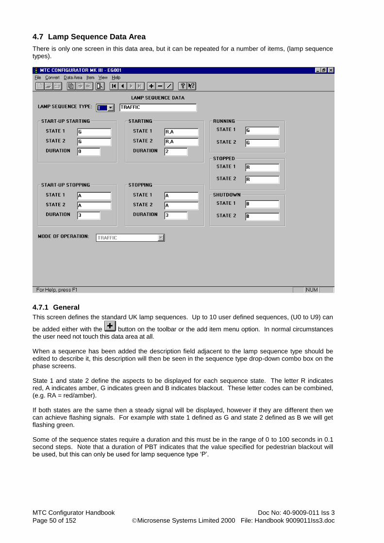
MTC Configurator Handbook Doc No: 40-9009-011 Iss 3
Page 50 of 152 Microsense Systems Limited 2000 File: Handbook 9009011Iss3.doc
4.7 Lamp Sequence Data Area
There is only one screen in this data area, but it can be repeated for a number of items, (lamp sequence types).
4.7.1 General
This screen defines the standard UK lamp sequences. Up to 10 user defined sequences, (U0 to U9) can
be added either with the button on the toolbar or the add item menu option. In normal circumstances the user need not touch this data area at all. When a sequence has been added the description field adjacent to the lamp sequence type should be edited to describe it, this description will then be seen in the sequence type drop-down combo box on the phase screens. State 1 and state 2 define the aspects to be displayed for each sequence state. The letter R indicates red, A indicates amber, G indicates green and B indicates blackout. These letter codes can be combined, (e.g. RA = red/amber). If both states are the same then a steady signal will be displayed, however if they are different then we can achieve flashing signals. For example with state 1 defined as G and state 2 defined as B we will get flashing green. Some of the sequence states require a duration and this must be in the range of 0 to 100 seconds in 0.1 second steps. Note that a duration of PBT indicates that the value specified for pedestrian blackout will be used, but this can only be used for lamp sequence type ‘P’.

Doc No: 40-9009-011 Iss 3 MTC Configurator Handbook
File: Handbook 9009011Iss3.doc Microsense Systems Limited 2000 Page 51 of 152
4.7.2 Mode Of Operation (TR0141C Format Configurations Only)
Mode of operation is used to specify which base type lamp sequence the controller should treat any user-defined sequence as. The five possible base types are as following Traffic, Pelican Traffic, Near-side Pedestrian, Far-side Pedestrian and Pelican Pedestrian.

MTC Configurator Handbook Doc No: 40-9009-011 Iss 3
Page 52 of 152 Microsense Systems Limited 2000 File: Handbook 9009011Iss3.doc
4.8 Stage Data Area
There is only one screen in this data area, but it can be repeated for a number of items, (stage streams).
4.8.1 General
This screen is used to define stage data for up to 8 parallel stage streams. Use the button on the toolbar or the add item menu option to add stage streams as required. Note that when a configuration is first created no streams exist.
4.8.2 Start-Up Stage Number
The start-up stage number must be in the range of 0 to 15. The default is stage 1.
4.8.3 Number Of Stages
The number of stages must be between 0 and 15. The value entered should be the last required stage number + 1. Note that each stream starts from stage 0.
4.8.4 List Active Phases
For each stage required list the phases that may appear, including dummy phases, but excluding switched signs. Note that multiple phase id’s must be separated by commas. Each stage, excluding any all red stage(s), must contain at least one type 0 appearance phase, (i.e. fixed) and this sometimes means that a dummy phase has to be included, (e.g. where a stage contains only demand dependant pedestrian phases).
4.8.5 Stand Alone Pedestrian Stream (TR0141C Format Configurations Only)
Any stream that is only used to implement a pedestrian crossing must be marked as a stand alone pedestrian stream under TR0141C.

Doc No: 40-9009-011 Iss 3 MTC Configurator Handbook
File: Handbook 9009011Iss3.doc Microsense Systems Limited 2000 Page 53 of 152
4.9 Switched Sign Data Area
There is only one screen in this data area, but it can be repeated for a number of items, (signs).
4.9.1 General
This screen is used to define data for up to 16 switched signs. Use the button on the toolbar or the add item menu option to add signs as required. Signs may be switched by the timetable, (see Timetable Entry data area and Timetable Event List data area), by a UTC 'SF' bit, (see UTC Mode data area) or by special conditioning, (see Special Conditioning data area). If one or more methods are used for requesting then any one may request the sign to be on, but all requests must be OFF before it can be extinguished. Care should be taken when using switched signs with security with regard to conflict conditions.
4.9.2 UTC Reply Bit Name
UTC reply bit name can be either N/A if the facility is not required or one of the pre-defined reply bit names, (SC1 to SC16). If using a UTC reply bit name it must be entered in the Input/Output data area.
4.9.3 Switched Signs With Security
Switched signs with security are ones allocated to a phase green, so that they may have conflicts associated with them. This option is selected/deselected by the adjacent check box.
4.9.4 Conflicting Phase Greens
Conflicting phase greens need only be filled in for switched signs with security. This may contain real phases and/or other signs with security. When referring to another sign you must enter the phase id for the green aspect used. Note that multiple phase id’s must be separated by commas.

MTC Configurator Handbook Doc No: 40-9009-011 Iss 3
Page 54 of 152 Microsense Systems Limited 2000 File: Handbook 9009011Iss3.doc
4.9.5 Switch On/Off Stage/Phase
For switch on/off stage/phase, note that switching occurs at the start of the specified stage/phase. Real or dummy phases may be specified. The switch on and switch off conditions may be different. If switching is to occur immediately on request or via special conditioning then leave blank.
4.9.6 Associated With Stream
The associated stream is used for reference to switch on/off stages and also for extinguishing the sign if that stream is shutdown.
4.9.7 Phase Drive Used
For phase drive used enter the phase letter, (A to Z, A2 to F2) and the aspect colour (R, A or G).
4.9.8 Associated LRT Phase(s)
For LRT centre lamp drives, list the associated LRT phase(s). Note that multiple phase id’s must be separated by commas.
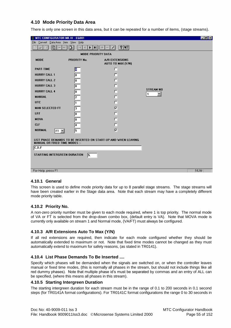
Doc No: 40-9009-011 Iss 3 MTC Configurator Handbook
File: Handbook 9009011Iss3.doc Microsense Systems Limited 2000 Page 55 of 152
4.10 Mode Priority Data Area
There is only one screen in this data area, but it can be repeated for a number of items, (stage streams).
4.10.1 General
This screen is used to define mode priority data for up to 8 parallel stage streams. The stage streams will have been created earlier in the Stage data area. Note that each stream may have a completely different mode priority table.
4.10.2 Priority No.
A non-zero priority number must be given to each mode required, where 1 is top priority. The normal mode of VA or FT is selected from the drop-down combo box, (default entry is VA). Note that MOVA mode is currently only available on stream 1 and Normal mode, (VA/FT) must always be configured.
4.10.3 A/R Extensions Auto To Max (Y/N)
If all red extensions are required, then indicate for each mode configured whether they should be automatically extended to maximum or not. Note that fixed time modes cannot be changed as they must automatically extend to maximum for safety reasons, (as stated in TR0141).
4.10.4 List Phase Demands To Be Inserted ....
Specify which phases will be demanded when the signals are switched on, or when the controller leaves manual or fixed time modes, (this is normally all phases in the stream, but should not include things like all red dummy phases). Note that multiple phase id’s must be separated by commas and an entry of ALL can be specified, (where this means all phases in this stream).
4.10.5 Starting Intergreen Duration
The starting intergreen duration for each stream must be in the range of 0.1 to 200 seconds in 0.1 second steps (for TR0141A format configurations). For TR0141C format configurations the range 0 to 30 seconds in

MTC Configurator Handbook Doc No: 40-9009-011 Iss 3
Page 56 of 152 Microsense Systems Limited 2000 File: Handbook 9009011Iss3.doc
steps of 0.1 seconds must be used. Note that this time should not include the amber period for phases not in the start-up stage. The default value is 7 seconds.
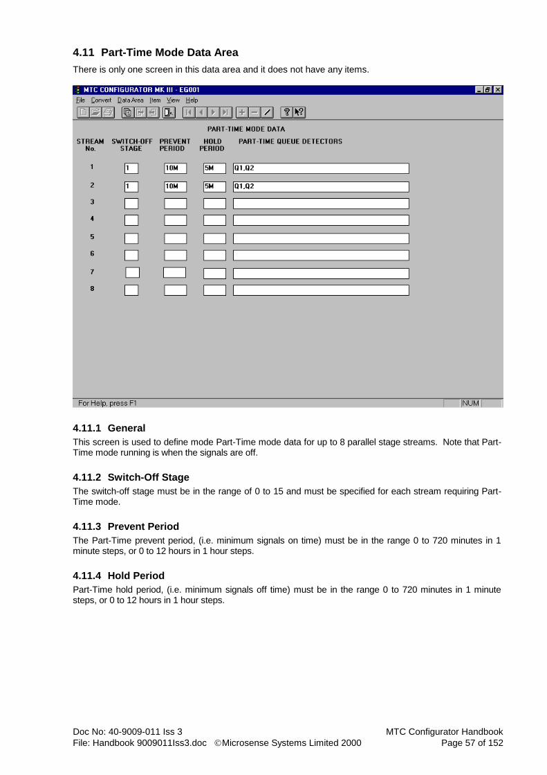
Doc No: 40-9009-011 Iss 3 MTC Configurator Handbook
File: Handbook 9009011Iss3.doc Microsense Systems Limited 2000 Page 57 of 152
4.11 Part-Time Mode Data Area
There is only one screen in this data area and it does not have any items.
4.11.1 General
This screen is used to define mode Part-Time mode data for up to 8 parallel stage streams. Note that Part-Time mode running is when the signals are off.
4.11.2 Switch-Off Stage
The switch-off stage must be in the range of 0 to 15 and must be specified for each stream requiring Part-Time mode.
4.11.3 Prevent Period
The Part-Time prevent period, (i.e. minimum signals on time) must be in the range 0 to 720 minutes in 1 minute steps, or 0 to 12 hours in 1 hour steps.
4.11.4 Hold Period
Part-Time hold period, (i.e. minimum signals off time) must be in the range 0 to 720 minutes in 1 minute steps, or 0 to 12 hours in 1 hour steps.

MTC Configurator Handbook Doc No: 40-9009-011 Iss 3
Page 58 of 152 Microsense Systems Limited 2000 File: Handbook 9009011Iss3.doc
4.11.5 Part-Time Queue Detectors
For Part-Time queue detectors enter the name(s) of detectors which when active cause the controller to leave part-time mode (i.e. switch the signals on). The detector name(s) specified here must be defined in the Detector data area. Note that multiple detector names must be separated by commas. Where more than one detector name is specified then the queue condition to bring the signals out of Part-Time mode is ALL detectors active. If a different combination of detectors were required then a dummy detector must be used which is set active by special conditioning when the appropriate combination is achieved. Note that Part-Time mode may also be requested/cancelled by the timetable, (see Timetable Entry data area and Timetable Event List data area), by a UTC 'LO' bit, (see UTC Mode data area) or by special conditioning, (see Special Conditioning data area). If more than one method is used for requesting Part-Time mode then all must be requesting it before the signals will switch off, but only one needs to ask for cancellation of Part-Time mode for the signals to switch back on again.

Doc No: 40-9009-011 Iss 3 MTC Configurator Handbook
File: Handbook 9009011Iss3.doc Microsense Systems Limited 2000 Page 59 of 152
4.12 Hurry Call Mode Data Area
There is only one screen in this data area, but it can be repeated for a number of items, (stage streams).
4.12.1 General
This screen is used to define Hurry Call mode data for up to 8 parallel stage streams. The stage streams will have been created earlier in the Stage data area. Note that there are a possible 4 Hurry Calls available to each stage stream. Also note that a hurry call detector can only be used once per stream as either a request or cancel detector.
4.12.2 Call Stage
For each Hurry Call required the call stage must be in the range of 0 to 15 and must be a configured stage, (see Stage data area).
4.12.3 Request Detectors
For request detectors enter the name(s) of detectors which when active cause the request of that particular hurry call. The detector name(s) specified here must be defined later in the Detector data area. Note that multiple detector names must be separated by commas. Where more than one detector name is specified then the request condition is ANY detector active. If a different combination of detectors were required then a dummy detector must be used which is set active by special conditioning when the appropriate combination is achieved.

MTC Configurator Handbook Doc No: 40-9009-011 Iss 3
Page 60 of 152 Microsense Systems Limited 2000 File: Handbook 9009011Iss3.doc
4.12.4 Cancel Detectors
For cancel detectors enter the name(s) of detectors which when active cause the cancellation of that particular hurry call. The detector name(s) specified here must be defined later in the Detector data area. Note that multiple detector names must be separated by commas. Where more than one detector name is specified then the cancel condition is ANY detector active. If a different combination of detectors were required then a dummy detector must be used which is set active by special conditioning when the appropriate combination is achieved.
4.12.5 Confirm O/P Name
The confirm O/P name can be either N/A if the facility is not required or one of the pre-defined output names, (HR01 to HR32). The output is set at the start of the delay period and is removed at the end of the hold period. Where an output name is used this must be defined later in the Input/Output data area.
4.12.6 Delay Period
The delay period must be in the range of 0 to 300 seconds in 0.1 second steps.
4.12.7 Hold Period
The hold period must be in the range of 0 to 300 seconds in 0.1 second steps. Note that the hold and prevent periods both commence at the start of the hurry call stage.
4.12.8 Prevent Period
The prevent period must be in the range of 0 to 500 seconds in 0.1 second steps for TR0141A format configurations. For TR0141C format configurations the range 0 to 300 seconds in steps of 0.1 seconds must be used. Note that the hold and prevent periods both commence at the start of the hurry call stage.
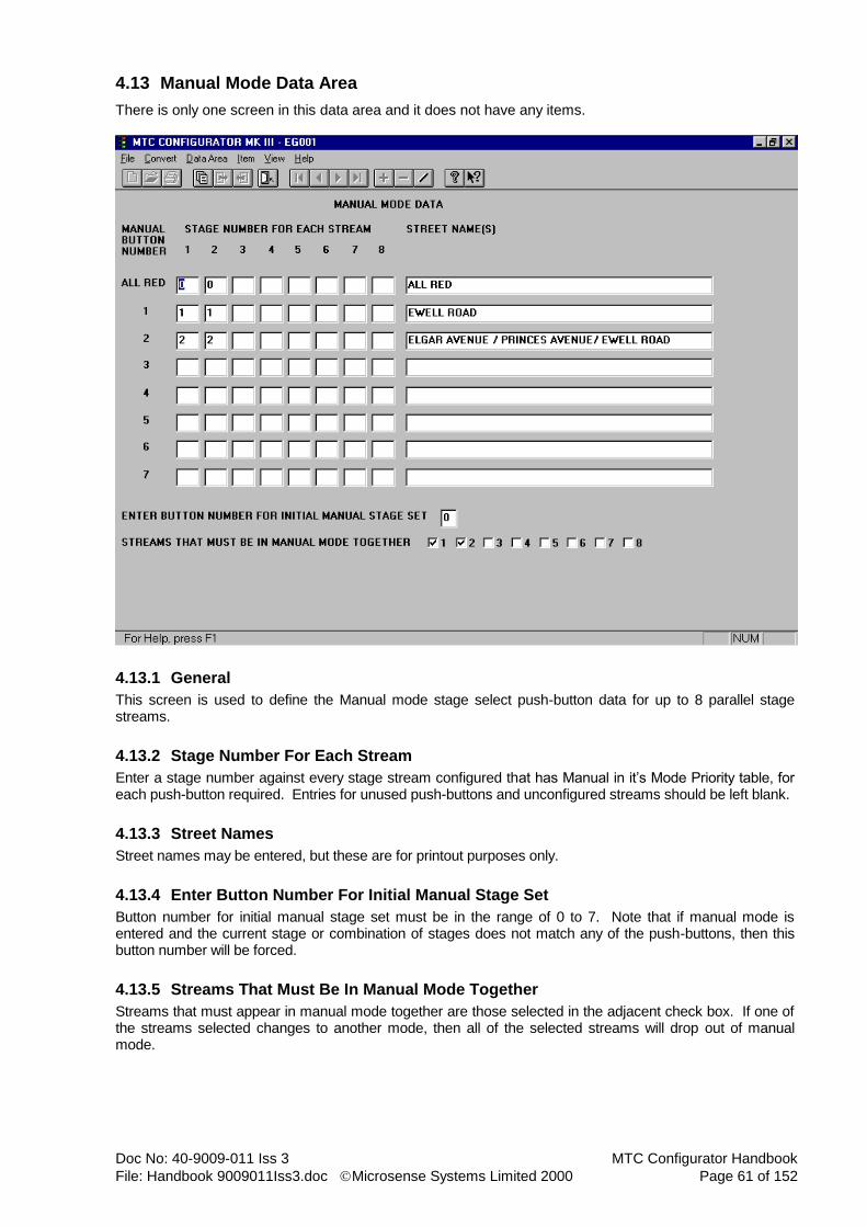
Doc No: 40-9009-011 Iss 3 MTC Configurator Handbook
File: Handbook 9009011Iss3.doc Microsense Systems Limited 2000 Page 61 of 152
4.13 Manual Mode Data Area
There is only one screen in this data area and it does not have any items.
4.13.1 General
This screen is used to define the Manual mode stage select push-button data for up to 8 parallel stage streams.
4.13.2 Stage Number For Each Stream
Enter a stage number against every stage stream configured that has Manual in it’s Mode Priority table, for each push-button required. Entries for unused push-buttons and unconfigured streams should be left blank.
4.13.3 Street Names
Street names may be entered, but these are for printout purposes only.
4.13.4 Enter Button Number For Initial Manual Stage Set
Button number for initial manual stage set must be in the range of 0 to 7. Note that if manual mode is entered and the current stage or combination of stages does not match any of the push-buttons, then this button number will be forced.
4.13.5 Streams That Must Be In Manual Mode Together
Streams that must appear in manual mode together are those selected in the adjacent check box. If one of the streams selected changes to another mode, then all of the selected streams will drop out of manual mode.

MTC Configurator Handbook Doc No: 40-9009-011 Iss 3
Page 62 of 152 Microsense Systems Limited 2000 File: Handbook 9009011Iss3.doc
4.14 UTC Mode Data Area
There are eight screens (ten for TR0141C configurations) in this data area, one of which has items as well, (screen 2 - Force bits). Note that when a configuration is first created no UTC data exists.
4.14.1 Screen 1
4.14.1.1 General
This screen is used to define general UTC interface data relating to all parallel stage streams.
4.14.1.2 UTC Control Option
UTC control option is selected using the drop down combo box and may be any of the following :- 1 - MCE 0105/0106, (default entry) 2 - TCD 316 3 - VA SELECTION
4.14.1.3 Stream Linking Options
For a parallel stage streaming configuration enter the required stream linking options using the drop-down combo boxes. Linking options may be UNLINKED (default entry), MASTER or SLAVE. Note that unlinked streams will enter UTC mode as soon as they have a force bit active. Master streams must all have force bits active before any of them can enter UTC mode. Slave streams cannot enter UTC mode unless they have force bits active and all master streams also have force bits active. Also note that an LL-bit can be used to inhibit this linking, (i.e. the appropriate stream(s) will operate as unlinked).

Doc No: 40-9009-011 Iss 3 MTC Configurator Handbook
File: Handbook 9009011Iss3.doc Microsense Systems Limited 2000 Page 63 of 152
4.14.1.4 Use Serial Interface for UTC
If a serial UTC interface is to be employed, check this box. For a serial interface an OMTU is normally required to communicate with the instation. Also MTC firmware C24090010xx issue 12 or later is necessary to support the interface.
4.14.1.5 Sync Confirm Times
Sync confirm times, (for RT and SR reply bits) must be in the range of 1 to 10 seconds in 1 second steps. The default value is 3 seconds for both. To obtain different length durations for RT depending on the day of week special conditioning must be used.
4.14.1.6 TF Bit Reset Time
The TF bit reset time must be in HH:MM:SS format, (for a 24 hour clock).
4.14.1.7 Time Sync Data
The time sync data, (for the TS control bit) should be entered as follows:- Day type can be MON, TUE, WED, THU, FRI, SAT, SUN or ANY. If day type is not ANY then the date will also be changed when a valid TS bit is received. Reference time must be in HH:MM:SS format, (for a 24 hour clock). This is the time to which the clock will be set. Repeat rate must be in the range of 1 - 24 hours in steps of 1 hour, or 1 - 1440 minutes in steps of 1 minute. Note that for a day type other than ANY this is not applicable. This time must be wholly divisible into 24 hours. Window time must be in the range of 1 - 24 hours in steps of 1 hour, or 1 - 1440 minutes in steps of 1 minute, or 2 - 86400 seconds in steps of 1 second. Note that for a day type other than ANY this is not applicable. This time must be less than or equal to the repeat rate. For a normal once a day time sync, day type should be set to ANY and repeat rate and window time should be set to 24H. Note that hour values must be suffixed with H, minute values with M and second values with S.
4.14.1.8 UTC Control Bit Names
The following list shows the UTC control bit names available in the MTC. Although these may not all relate to this screen, they are relevant for the whole data area. DX1 to DX8 - Common Demand. D01 to D32 - Stage Demand. F01 to F32 - Stage Force. SF01 to SF16 - Switch Facility, (switched sign request). SG - CLF Group Timer Synchronisation. SO - Solar Switch Override. LO1 to LO8 - Lamps On from PT mode. TS - Time Synchronisation. FM1 to FM8 - Fall Back Mode Selection. LL1 to LL8 - Local link inhibit. GO1 to GO8 - Gap out. LRTI1 to LRTI8 - LRT mode inhibit.

MTC Configurator Handbook Doc No: 40-9009-011 Iss 3
Page 64 of 152 Microsense Systems Limited 2000 File: Handbook 9009011Iss3.doc
4.14.1.9 UTC Reply Bit Names
The following list shows the UTC reply bit names available in the MTC. Although these may not all relate to this screen, they are relevant for the whole data area. DF - Detector Fault. G1 to G32 - Stage Green Confirm. FC1 to FC8 - Fall Back Mode Selection Confirm. SC1 to SC16 - Switch Facility Confirm. HC1 to HC8 - Hurry Call Confirm. FGR1 to FGR8 - First CLF Group Confirm. SD1 to SD32 - Stage Demand Confirm. SR - CLF Group Timer Sync Confirm. RT - Time Synchronisation Confirm. MC - Manual Control Mode. CF - Controller Fault. CW - Controller Warning. LE - Lamps Extinguished. RR - Remote Reconnect. TOR1 to TOR8 - Take Over Reply, (UTC mode active). TF - Test Facility (handset connection). * DC - Dim confirm. LRTR1 to LRTR8 - LRT mode running. LSF - Suspect LRT event. LDF - Failed LRT detector/event. LEV<phase><event> - LRT event confirm. # LM1 to 32 - ILM indication outputs. * Note that a handset plugged in causes the TF bit to be latched on until the next TF reset time. # Note that for LEV <phase> is the relevant phase id and <event> can be ‘P’ for prepare, ‘D’ for demand or ‘S’ for stopline.
4.14.1.10 UTC Active State (TR0141C Format Configurations Only)
The active state for the UTC inputs may be either OC, (open circuit) or SC, (short circuit) and can be selected from a drop-down combo box. The default entry is SC.

Doc No: 40-9009-011 Iss 3 MTC Configurator Handbook
File: Handbook 9009011Iss3.doc Microsense Systems Limited 2000 Page 65 of 152
4.14.2 Screen 2
4.14.2.1 General
This screen is used to define data for up to 32 UTC force bits, (F01 to F32). Use the button on the toolbar or the add item menu option to add a force bit.
4.14.2.2 Phase Demands To Be Considered ....
If this is a demand dependant force bit then enter the phase demand(s) to be considered, (i.e. those demands that will cause a force to the specified stage when active with the force bit). Note that multiple phase id’s must be separated by commas. Real or dummy phases may be specified.
4.14.2.3 Required Phase Extensions For ....
If this is a demand dependant force bit and UTC is running to Option 2, (TCD 316) then enter the phase(s) whose extensions are to hold the specified stage when active with the force bit. Note that multiple phase id’s must be separated by commas. Real or dummy phases may be specified.
4.14.2.4 Enter Stage To Force In Each Stream
Enter the required stage to be forced in the appropriate stream(s). If the stage is to be demand dependant add a # to the stage number, (e.g. 2#) and ensure that the phase demands to be considered field is filled in, (see above).

MTC Configurator Handbook Doc No: 40-9009-011 Iss 3
Page 66 of 152 Microsense Systems Limited 2000 File: Handbook 9009011Iss3.doc
4.14.3 Screen 3
4.14.3.1 General
This screen is used to define information regarding miscellaneous UTC control bits for up to 8 parallel stage streams.
4.14.3.2 LO/SF Qualification
The qualification period is the time for which the bit must be active or inactive before it is actioned. For compatibility with earlier versions of the configurator (TR0141A format configurations) LO/SF qualification periods must be in the range of 0 to 25.5 seconds in 0.1 second steps. For TR0141C format configurations the range 7 to 10 seconds in steps of 0.1 seconds must be used for SF qualification bits and the range 10 to 25.5 second in steps of 0.1 seconds must be used for LO qualification bits.
4.14.3.3 Control Bit - Stage Stream
For control bit stage stream association enter the required control bit name against the stream requiring the facility. Only MTC defined control bit names can be used here, (see lists under UTC screen 1). Note that one control bit name may be used to affect more than one stream, (e.g. if GO1 was entered in the columns for streams 1 and 2 then that bit when active would provide the gap-out facility on both streams).
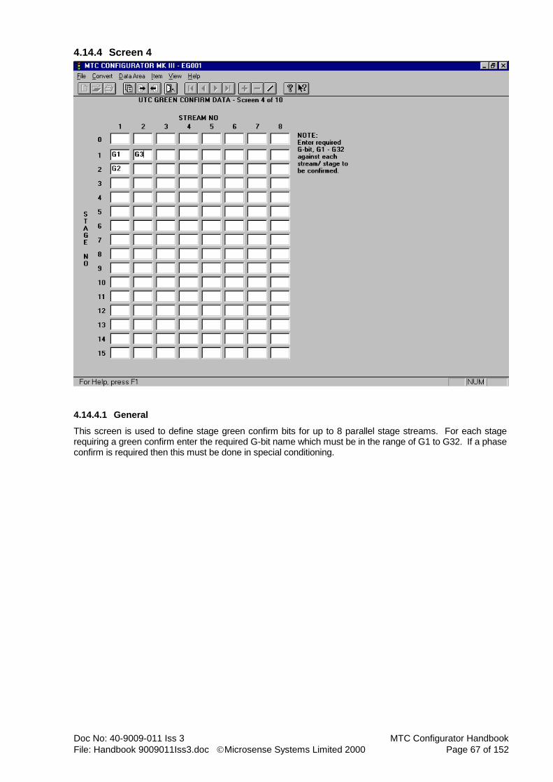
Doc No: 40-9009-011 Iss 3 MTC Configurator Handbook
File: Handbook 9009011Iss3.doc Microsense Systems Limited 2000 Page 67 of 152
4.14.4 Screen 4
4.14.4.1 General
This screen is used to define stage green confirm bits for up to 8 parallel stage streams. For each stage requiring a green confirm enter the required G-bit name which must be in the range of G1 to G32. If a phase confirm is required then this must be done in special conditioning.

MTC Configurator Handbook Doc No: 40-9009-011 Iss 3
Page 68 of 152 Microsense Systems Limited 2000 File: Handbook 9009011Iss3.doc
4.14.5 Screen 5
4.14.5.1 General
This screen is used to define information regarding miscellaneous UTC reply bits for up to 8 parallel stage streams.
4.14.5.2 Reply Bit - Stage Stream
For reply bit stage stream association enter the required reply bit name against the stream requiring the facility. It is advisable to use MTC defined reply bit names here, (see lists under UTC screen 1), however any six character name may be used so long as it is defined in the Input/Output data area. Note that one reply bit name may be used for more than one stream, (e.g. if TOR1 was entered in the columns for streams 1 and 2 then that bit would reply if UTC mode were active on either one of the two streams).

Doc No: 40-9009-011 Iss 3 MTC Configurator Handbook
File: Handbook 9009011Iss3.doc Microsense Systems Limited 2000 Page 69 of 152
4.14.6 Screen 6
4.14.6.1 General
This screen is used to define information regarding UTC demand bits for up to 32 stage demand bits, (D01 to D32) and 8 common demand bits, (DX1 to DX8).
4.14.6.2 Latched/Unlatched Stages
For latched/unlatched stages enter the stage(s) to be demanded, in <stream>.<stage> format, (e.g. 2.4 = stream 2, stage 4). Note that multiple stage id’s must be separated by commas.
4.14.6.3 Latched/Unlatched Phases
For latched/unlatched phases enter the phase(s) to be demanded. Note that multiple phase id’s must be separated by commas. Real or dummy phases may be specified.
4.14.6.4 Phase Extends
For phase extends enter the phase(s) to be extended. Note that multiple phase id’s must be separated by commas. Real or dummy phases may be specified.

MTC Configurator Handbook Doc No: 40-9009-011 Iss 3
Page 70 of 152 Microsense Systems Limited 2000 File: Handbook 9009011Iss3.doc
4.14.7 Screen 7
4.14.7.1 General
This screen is used to define information regarding UTC demand reply bits. There are up to 32 available, (SD01 to SD32).
4.14.7.2 Stage Demands
For stage demands enter the stage(s) whose demands are to be replied, in <stream>.<stage> format, (e.g. 2.4 = stream 2, stage 4). Note that multiple stage id’s must be separated by commas.
4.14.7.3 Phase Demands
For phase demands enter the phase(s) whose demands are to be replied. Note that multiple phase id’s must be separated by commas. Real or dummy phases may be specified.

Doc No: 40-9009-011 Iss 3 MTC Configurator Handbook
File: Handbook 9009011Iss3.doc Microsense Systems Limited 2000 Page 71 of 152
4.14.8 Screen 8 (TR0141C Format Configurations Only)
4.14.8.1 General
This screen is used to specify the timeout durations for those UTC bit types that are allowed timeouts. For each UTC bit types check the box adjacent to the ‘No timeout allowed’ if the timeouts are NOT required. Note PV and F bit types always require timeouts. F bits must be in the range of 120 to 300 seconds in 1 second steps (the default is 200 seconds). PV bits must be in the range of 60 to 3600 seconds in 1 second steps (the default is 500 seconds). All other bit types must be in the range of 20 to 3600 seconds in 1 second steps.

MTC Configurator Handbook Doc No: 40-9009-011 Iss 3
Page 72 of 152 Microsense Systems Limited 2000 File: Handbook 9009011Iss3.doc
4.14.9 Screen 9 (TR0141C Format Configurations Only)
4.14.9.1 General
This screen is used to define the pedestrian phases that have local PV inhibited by each UTC LL bit.

Doc No: 40-9009-011 Iss 3 MTC Configurator Handbook
File: Handbook 9009011Iss3.doc Microsense Systems Limited 2000 Page 73 of 152
4.14.10 Screen 10 (Screen 8 for TR0141A Configurations)
4.14.10.1 General
This screen is used to define miscellaneous UTC confirm data. For each controller state requiring confirmation enter the appropriate reply bit name(s). These reply bit names must be defined in the Input/Output data area). Note that multiple reply bit names must be separated by commas.
4.14.10.2 Record These Warnings (TR0141C Format Configurations Only)
Any warning checked will be consider when generating UTC warning log reports. The warnings are as follows:-
BRN - Mains brownout. CDM - Cyclic DFM faults. DFC - Detector faults cleared. DFM - Detector fault monitor. DOG - Watchdog. LFD - Failed LRT detector warning. LFE - Failed LRT event warning. LMF - Lamp monitoring fault. LMT - Lamp monitoring toroid faults. LMV - Lamp monitoring mains voltage unstable fault. LSE - Suspect LRT event warning. MOV - MOVA error warning. MSW - Main processor software warning. RD1 - 1st red lamp failure. RD2 - 2nd red lamp failure. RES - Reset after power fail. SSW - Secondary processor software warning. SZX - Secondary processor ZXO lost for more than 200ms. WLC - Warning log cleared.

MTC Configurator Handbook Doc No: 40-9009-011 Iss 3
Page 74 of 152 Microsense Systems Limited 2000 File: Handbook 9009011Iss3.doc
4.15 FT/VA Mode Data Area
There is only one screen in this data area, but it can be repeated for a number of items, (stage streams).
4.15.1 General
This screen is used to define FT/VA mode data for up to 8 parallel stage streams. The stage streams will have been created earlier in the Stage data area.
4.15.2 FT Mode
FT mode option may be either of the following:- FT - normal fixed time, (with fixed stage times). VA - VA mode running to current maximums, (default).
4.15.3 FT Mode/Timed Option
For FT mode/timed option, against each configured stage enter a stage time in the range of 0 to 300 seconds in 0.1 second steps and a to stage in the range of 0 to 15. Note that the duration entered is green time only. For stages that do not normally run in FT mode give them a to stage that does run in FT mode and a duration of 0, (note that the stage will still have to run for its minimum green time).
Doc No: 40-9009-011 Iss 3 MTC Configurator Handbook
File: Handbook 9009011Iss3.doc Microsense Systems Limited 2000 Page 75 of 152
4.15.4 FT Mode/VA To Current Maxes Option (TR0141A Format Configurations Only)
Demand dependant phases should only be specified when fixed time mode is running VA to current maximums, (see FT Mode option above). Any phases in the selected stream that do not appear in demand dependant phases will have a permanent demand/extension applied during fixed time mode. Care should be taken to ensure that phases not required to appear in fixed time mode, (e.g. all red dummy) are specified in this field, as well as those phases required to be truly demand dependant.
4.15.5 VA Mode
Arterial reversion to stage/phase is only applicable for VA mode and may be in the range of 0 to 15 for a stage or A to Z, A2 to F2 or DA to DZ for a phase. This field should be left blank for no arterial reversion. VA stage selection option can either be NEAR, (default) where the controller always selects the nearest stage in cyclic order to satisfy the demands present, or FAR where it will select the farthest stage to satisfy the demands present. When using the FAR option the controller cannot skip over phase demands. Term on max stage changes are selected by the adjacent check box. Note that a term on max stage change is where a stage containing vehicles and pedestrians runs to maximum, (on all vehicles) and the vehicles are held at green until the pedestrian blackout period expires. This is an option in TR0141 and is defaulted to not selected.

MTC Configurator Handbook Doc No: 40-9009-011 Iss 3
Page 76 of 152 Microsense Systems Limited 2000 File: Handbook 9009011Iss3.doc
4.16 CLF Mode Data Area
There is only one screen in this data area, but it can be repeated for a number of items, (CLF plans).
4.16.1 General
This screen is used to define data for up to 16 CLF plans and allows data for all 8 streams. Use the button on the toolbar or the add item menu option to add a CLF plan. For each CLF plan up to 32 groups are available. Use the add/delete group buttons to obtain the required number of groups. Note that each stream may use a different number of groups all with differing start times, so you must add enough groups to cover the stream requiring the most.
4.16.2 Delay Time
Plan delay time must be in the range of 0 to 300 seconds in 0.1 second steps for TR0141A format configurations. For TR0141C format configurations the range 0 to 200 seconds in steps of 0.1 seconds must be used. This duration delays the start of the plan from a timetable event.
4.16.3 Cycle Time
Cycle time must be in the range of 0 to 3000 seconds in 0.1 second steps (for TR0141A format configurations) and must be greater than the highest group start time. For TR0141C format configurations the range 0 to 200 seconds in steps of 0.1 seconds must be used.
4.16.4 Stream Offset Time
Stream offset times should be in the range 0 to 300 seconds in 0.1 second steps for TR0141A format configurations. For TR0141C format configurations the range 0 to 200 seconds in steps of 0.1 seconds must be used. The stream offset timers start once the plan has started, (i.e. after any plan delay time).

Doc No: 40-9009-011 Iss 3 MTC Configurator Handbook
File: Handbook 9009011Iss3.doc Microsense Systems Limited 2000 Page 77 of 152
4.16.5 Stream Time
The times specified for each group/stream are start times and they must be in the range of 0 to 3000 seconds in 0.1 second steps for TR0141A format configurations. For TR0141C format configurations the range 0 to 200 seconds in steps of 0.1 seconds must be used. Note that group 1 start time MUST always be 0 on every stream, (hence the need for stream offset times), however all other group start times may be different across the streams.
4.16.6 Stream Influence
Group influences may be any one of the following :- IS - Isolate to VA, (no maxes). IM - Immediate move to stage (n). DM - Demand dependant move to stage (n). HS - Hold current stage. PX - Prevent moves except to stage (n). AI - Add immediate move to stage (n) to existing influence. AD - Add demand dependant move to stage (n) to existing influence. Note that an add influence, (AI or AD) will only be actioned if the preceding influence has not been actioned. These generally follow DM influences.
4.16.7 Stream Stage
Group influence stages must be in the range of 0 to 15 and are only required with influences of IM, DM, PX, AI and AD as shown above. For influences of IS and HS leave blank.

MTC Configurator Handbook Doc No: 40-9009-011 Iss 3
Page 78 of 152 Microsense Systems Limited 2000 File: Handbook 9009011Iss3.doc
4.17 Stage To Stage Movement Data Area
There are two screens in this data area, the second of which has items, (stage to stage movement tables).
4.17.1 Screen 1
4.17.1.1 General
This screen is used to specify which stage to stage movement table, (as defined on screen 2) is to be used by which mode/stream. There are 32 tables available and common tables can be used by one or more modes/streams. Note that a blank entry signifies that all movements in this mode/stream are allowed.
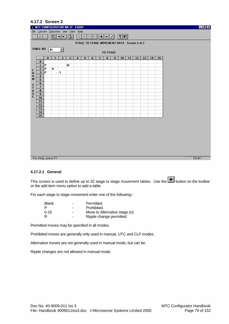
Doc No: 40-9009-011 Iss 3 MTC Configurator Handbook
File: Handbook 9009011Iss3.doc Microsense Systems Limited 2000 Page 79 of 152
4.17.2 Screen 2
4.17.2.1 General
This screen is used to define up to 32 stage to stage movement tables. Use the button on the toolbar or the add item menu option to add a table. For each stage to stage movement enter one of the following:- Blank - Permitted. P - Prohibited. 0-15 - Move to Alternative stage (n). R - Ripple change permitted. Permitted moves may be specified in all modes. Prohibited moves are generally only used in manual, UTC and CLF modes. Alternative moves are not generally used in manual mode, but can be. Ripple changes are not allowed in manual mode.
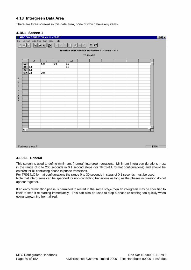
MTC Configurator Handbook Doc No: 40-9009-011 Iss 3
Page 80 of 152 Microsense Systems Limited 2000 File: Handbook 9009011Iss3.doc
4.18 Intergreen Data Area
There are three screens in this data area, none of which have any items.
4.18.1 Screen 1
4.18.1.1 General
This screen is used to define minimum, (normal) intergreen durations. Minimum intergreen durations must in the range of 0 to 200 seconds in 0.1 second steps (for TR0141A format configurations) and should be entered for all conflicting phase to phase transitions. For TR0141C format configurations the range 0 to 30 seconds in steps of 0.1 seconds must be used. Note that intergreens can be specified for non-conflicting transitions as long as the phases in question do not appear together. If an early termination phase is permitted to restart in the same stage then an intergreen may be specified to itself to stop it re-starting immediately. This can also be used to stop a phase re-starting too quickly when going to/returning from all red.
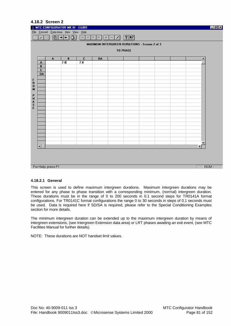
Doc No: 40-9009-011 Iss 3 MTC Configurator Handbook
File: Handbook 9009011Iss3.doc Microsense Systems Limited 2000 Page 81 of 152
4.18.2 Screen 2
4.18.2.1 General
This screen is used to define maximum intergreen durations. Maximum intergreen durations may be entered for any phase to phase transition with a corresponding minimum, (normal) intergreen duration. These durations must be in the range of 0 to 200 seconds in 0.1 second steps for TR0141A format configurations. For TR0141C format configurations the range 0 to 30 seconds in steps of 0.1 seconds must be used. Data is required here if SD/SA is required, please refer to the Special Conditioning Examples section for more details. The minimum intergreen duration can be extended up to the maximum intergreen duration by means of intergreen extensions, (see Intergreen Extension data area) or LRT phases awaiting an exit event, (see MTC Facilities Manual for further details). NOTE: These durations are NOT handset limit values.

MTC Configurator Handbook Doc No: 40-9009-011 Iss 3
Page 82 of 152 Microsense Systems Limited 2000 File: Handbook 9009011Iss3.doc
4.18.3 Screen 3
4.18.3.1 General
This screen is used to define intergreen minimum limit values for handset use. Intergreen minimum limit values should be entered for all phase to phase transitions with a corresponding minimum, (normal) intergreen duration. These values must be in the range of 0 to 200 seconds in 0.1 second steps for TR0141A format configurations. For TR0141C format configurations the range 0 to 30 seconds in steps of 0.1 seconds must be used.

Doc No: 40-9009-011 Iss 3 MTC Configurator Handbook
File: Handbook 9009011Iss3.doc Microsense Systems Limited 2000 Page 83 of 152
4.19 Phase Delay Data Area
There is only one screen in this data area and it does not have any items.
4.19.1 General
This screen is used to define up to 256 phase delays. Use the button on the toolbar or the add item menu option to add a phase delay.
4.19.2 Losing/Gaining Stage
The losing/gaining stage must be in the range of 0 to 15 and must be configured in the Stage data area. Note that the stage stream number is not needed here as the controller works it out from the associated phase id.
4.19.3 Assoc Phase
The associated phase must be a previously configured phase id, (real or dummy). Note that the phase must appear in either the losing or gaining stage, but not both.
4.19.4 Delay Period
The delay period must be in the range of 0.1 to 300 seconds in 0.1 second steps for TR0141A format configurations. For TR0141C format configurations the range 0 to 60 seconds in steps of 0.1 seconds must be used. Delays of 0 second duration cannot be configured for TR0141A format configurations, but delays can be added/deleted as required using the handset.

MTC Configurator Handbook Doc No: 40-9009-011 Iss 3
Page 84 of 152 Microsense Systems Limited 2000 File: Handbook 9009011Iss3.doc
4.20 Detector Data Area (TR0141A Format Configurations)
There is only one screen in this data area, but it can be repeated for a number of items, (detectors).
4.20.1 General
This screen is used to define data for up to 96 detectors. Use the button on the toolbar or the add item menu option to add a detector. Data is required here if SD/SA is required, please refer to the Special Conditioning Examples section for more details.
4.20.2 Name
The detector name may be up to 6 characters and must NOT include any of the 4 following characters / :
; - as these will upset the operation of the handset when looking at detector related commands, as they
are delimiter characters.
4.20.3 Detector Type
The detector type may be any one of the following:- NM - Normal, (i.e. when not one of the following - default). PB - Pedestrian push-button. UD - Unidirectional, (2 inputs required). DD - Dummy detector, (for special conditioning use). LRT - Normal LRT input. LRTC - LRT inputs with checkable failure pattern. VWD - VIS unit watchdog input.
4.20.4 Count Detector
Any detector can be marked for use as a count detector. This does not affect the normal usage of the detector. This item has been added for compatibility with future MTC software.
Doc No: 40-9009-011 Iss 3 MTC Configurator Handbook
File: Handbook 9009011Iss3.doc Microsense Systems Limited 2000 Page 85 of 152
4.20.5 Input No.
The input number must be in the range of 0 to 55. Care must be taken to ensure that an input designated for a UTC control bit is not used for a detector input. UTC control bits are usually defined on inputs 0 to 15, so detector inputs would start at 16. However if UTC is not configured detector inputs can start from 0. Note that dummy detectors do not require an input number, so it can be left blank.
4.20.6 Assoc Input No.
The associated input number must be in the range of 0 to 55 and is only required for a UD type of detector, (input number will be the entry loop and associated input number will be the leaving loop). This number will ideally be the next consecutive input number after the entry loop, but it does not have to be. If detector is not UD then leave blank.
4.20.7 Assoc VIS Unit No.
The associated VIS unit number must be in the range of 1 to 4 for LRT inputs from a VIS-OTU. Entering the associated VIS unit number allows LRT inputs to be associated with the appropriate watchdog input. If detector is not an LRT input then leave blank.
4.20.8 Active State
The active state for a detector input may be either OC, (open circuit) or SC, (short circuit) and can be selected from the drop-down combo box. Loop detector inputs are usually OC and pedestrian push-buttons are usually SC. The default entry is OC. Active state is not applicable for a dummy detector.
4.20.9 Illuminate Wait Lamps On Phases
This field only needs to be filled out for pedestrian push-button inputs, (type PB). Enter the phase(s) requiring wait indicators to be lit, (amber drive) when the push-button is pressed. Note that multiple phase id’s must be separated by commas. Only real phases may be specified.
4.20.10 Latched/Unlatched Phase Demands
For latched/unlatched phase demands enter the phase(s) to be demanded. Note that multiple phase id’s must be separated by commas. Real or dummy phases may be specified. A latched demand is set when the detector is activated and remains set until the phase runs, whereas an unlatched demand only exists while the detector is active. Demands cannot be registered when the phase is green.
4.20.11 Green Phase Extensions
For green phase extensions enter the phase(s) to be extended, each followed by the required extension time
in brackets, (e.g. A(1.5) ). The total number of green extension timers available is 256 and the extension time must be in the range of 0 to 100 seconds in 0.1 second steps. Note that multiple phase(extension time) combinations must be separated by commas. Real or dummy phases may be specified.
4.20.12 Varimax Phases
Varimax phases only need to be filled in if the detector is to perform vehicle counting for varimax operation. Enter the phase(s) that the detector will count for. Note that multiple phase id’s must be separated by commas. Real or dummy phases may be specified.

MTC Configurator Handbook Doc No: 40-9009-011 Iss 3
Page 86 of 152 Microsense Systems Limited 2000 File: Handbook 9009011Iss3.doc
4.20.13 DFM Force State
The DFM force state may be any one of the following:- A - force input active on DFM failure, (default). I - force input inactive on DFM failure. N - No state forced on DFM failure, (i.e. use input).
4.20.14 DFM Timings
DFM active times, (DFA) and DFM inactive times, (DFI) must be in the range of 0 to 15300 minutes in 1 minute steps, or 0 to 255 hours in 1 hour steps. Note that minute values must be suffixed with M and hour values with H. If DFM is not required then all timings must be entered as 0H. The 4 alternative timings form part of the detector timing set which may be changed via the timetable.
4.20.15 Call Cancel Timings
Call delay times, (DCL) and cancel delay times, (DCN) must be in the range of 0 to 300 seconds in 0.1 second steps. The 4 alternative timings form part of the detector timing set which may be changed via the timetable. Note that the call/cancel delay times are only used for entering/clearing demands.

Doc No: 40-9009-011 Iss 3 MTC Configurator Handbook
File: Handbook 9009011Iss3.doc Microsense Systems Limited 2000 Page 87 of 152
4.21 Detector Data Area (TR0141C Format Configurations)
There is only one screen in this data area, but it can be repeated for a number of items, (detectors).
4.21.1 General
This screen is used to define data for up to 96 detectors. Use the button on the toolbar or the add item menu option to add a detector. Data is required here if SD/SA is required, please refer to the Special Conditioning Examples section for more details.
4.21.2 Name
The detector name may be up to 6 characters and must NOT include any of the 4 following characters / :
; - as these will upset the operation of the handset when looking at detector related commands, as they
are delimiter characters.
4.21.3 Detector Type
The detector type may be any one of the following:- NM - Normal, (i.e. when not one of the following - default). PB - Pedestrian push-button. UD - Unidirectional, (2 inputs required). LRT - Normal LRT input. LRTC - LRT inputs with checkable failure pattern. VWD - VIS unit watchdog input. KS - Kerb-side pedestrian detector. ON - On-crossing pedestrian detector.
4.21.4 Dummy Detector
Any detector can be marked as a dummy detector for the purposes of special conditioning.
MTC Configurator Handbook Doc No: 40-9009-011 Iss 3
Page 88 of 152 Microsense Systems Limited 2000 File: Handbook 9009011Iss3.doc
4.21.5 Count Detector
Any detector can be marked for use as a count detector. This does not affect the normal usage of the detector. This item has been added for compatibility with future MTC software.
4.21.6 Input No.
The input number must be in the range of 0 to 55. Care must be taken to ensure that an input designated for a UTC control bit is not used for a detector input. UTC control bits are usually defined on inputs 0 to 15, so detector inputs would start at 16. However if UTC is not configured detector inputs can start from 0. Note that detectors marked as dummy detectors do not require an input number, so it can be left blank.
4.21.7 Assoc Input No.
The associated input number must be in the range of 0 to 55 and is only required for a UD type of detector, (input number will be the entry loop and associated input number will be the leaving loop). This number will ideally be the next consecutive input number after the entry loop, but it does not have to be. If detector is not UD then leave blank.
4.21.8 Assoc VIS Unit No.
The associated VIS unit number must be in the range of 1 to 4 for LRT inputs from a VIS-OTU. Entering the associated VIS unit number allows LRT inputs to be associated with the appropriate watchdog input. If detector is not an LRT input then leave blank.
4.21.9 Active State
The active state for a detector input may be either OC, (open circuit) or SC, (short circuit) and can be selected from the drop-down combo box. Loop detector inputs are usually OC and pedestrian push-buttons are usually SC. The default entry is OC. Active state is not applicable for detectors marked as dummy detectors.
4.21.10 Illuminate Wait Lamps On Phases
This field only needs to be filled out for pedestrian push-button inputs, (type PB). Enter the phase(s) requiring wait indicators to be lit, (amber drive) when the push-button is pressed. Note that multiple phase id’s must be separated by commas. Only real phases may be specified.
4.21.11 Latched/Unlatched Phase Demands
For latched/unlatched phase demands enter the phase(s) to be demanded. Note that multiple phase id’s must be separated by commas. Real or dummy phases may be specified. A latched demand is set when the detector is activated and remains set until the phase runs, whereas an unlatched demand only exists while the detector is active. Demands cannot be registered when the phase is green.
4.21.12 Green Phase Extensions
For green phase extensions enter the phase(s) to be extended, each followed by the required extension time
in brackets, (e.g. A(1.5) ). The total number of green extension timers available is 256 and the extension time must be in the range of 0.2 to 5 seconds in 0.1 second steps. Note that multiple phase(extension time) combinations must be separated by commas. Real or dummy phases may be specified.
4.21.13 Varimax Phases
Varimax phases only need to be filled in if the detector is to perform vehicle counting for varimax operation. Enter the phase(s) that the detector will count for. Note that multiple phase id’s must be separated by commas. Real or dummy phases may be specified.

Doc No: 40-9009-011 Iss 3 MTC Configurator Handbook
File: Handbook 9009011Iss3.doc Microsense Systems Limited 2000 Page 89 of 152
4.21.14 DFM Force State
The DFM force state may be any one of the following:- A - force input active on DFM failure, (default). I - force input inactive on DFM failure. N - No state forced on DFM failure, (i.e. use input).
4.21.15 DFM Timings
DFM active times, (DFA) and DFM inactive times, (DFI) must be in the range of 0 to 15300 minutes in 1 minute steps, or 0 to 255 hours in 1 hour steps. Note that minute values must be suffixed with M and hour values with H. If DFM is not required then all timings must be entered as 0H. The 4 alternative timings form part of the detector timing set which may be changed via the timetable.
4.21.16 Call Cancel Timings
Call delay times, (DCL) and cancel delay times, (DCN) must be in the range of 0 to 60 seconds in 0.1 second steps. The 4 alternative timings form part of the detector timing set which may be changed via the timetable. Note that the call/cancel delay times are only used for entering/clearing demands.
4.21.17 Pedestrian Information
Pedestrian information must be specified for pedestrian related detectors (i.e. PB, KS & ON detectors). A detector can only be related to one pedestrian phase. The extension period should also be specified and be in the range of 1 to 5 seconds in 0.1 second steps for pedestrian push-button and kerb-side detectors, (this is the demand extension). For on-crossing pedestrian detectors the extension period must be in the range of 0.4 to 5 seconds in 0.1 second steps.

MTC Configurator Handbook Doc No: 40-9009-011 Iss 3
Page 90 of 152 Microsense Systems Limited 2000 File: Handbook 9009011Iss3.doc
4.22 All Red Extension Data Area
There is only one screen in this data area and it does not have any items.
4.22.1 General
This screen is used to define up to 256 all red extensions. Use the button on the toolbar or the add item menu option to add an all red extension.
4.22.2 All Red Maximum Time
The all red maximum time must be in the range of 0 to 300 seconds in 0.1 second steps for TR0141A format configurations. For TR0141C format configurations the range 0 to 99 seconds in steps of 0.1 seconds must be used. Note that a time should be specified for every stream requiring all red extensions, but the values may be different.
4.22.3 Assoc Stream
The associated stream must be in the range of 1 to 8.
4.22.4 Losing/Gaining Stage
The losing/gaining stage must be in the range of 0 to 15 and must be different.
4.22.5 Assoc Detector
The associated detector can be of any type, but must have been previously defined in the detector data area.
4.22.6 Extension Time
The extension time must be in the range of 0 to 100 seconds in 0.1 second steps for TR0141A format configurations. For TR0141C format configurations the range 0 to 25 seconds in steps of 0.1 seconds must
Doc No: 40-9009-011 Iss 3 MTC Configurator Handbook
File: Handbook 9009011Iss3.doc Microsense Systems Limited 2000 Page 91 of 152
be used. Note that all red extensions are measured from the point at which the first phase in the new stage would normally start its red to green transition, (i.e. red/amber for a traffic phase).

MTC Configurator Handbook Doc No: 40-9009-011 Iss 3
Page 92 of 152 Microsense Systems Limited 2000 File: Handbook 9009011Iss3.doc
4.23 Intergreen Extension Data Area
There is only one screen in this data area and it does not have any items.
4.23.1 General
This screen is used to define up to 256 intergreen extensions. Use the button on the toolbar or the add item menu option to add an intergreen extension. Data is required here if SD/SA is required, please refer to the Special Conditioning Examples section for more details.
4.23.2 Losing/Gaining Phase
Losing/gaining phase must be a previously configured phase id, (real or dummy). These would normally be different, but could be the same, (i.e. you could have an extending intergreen from a phase back to itself)
4.23.3 Assoc Detector
The associated detector can be of any type, but must have been previously defined in the detector data area.
4.23.4 Extension Time
The extension time must be in the range of 0 to 300 seconds in 0.1 second steps. Note that if the associated detector is active at the end of the minimum, (normal) intergreen then it can extend the intergreen up to its maximum duration.

Doc No: 40-9009-011 Iss 3 MTC Configurator Handbook
File: Handbook 9009011Iss3.doc Microsense Systems Limited 2000 Page 93 of 152
4.24 Timetable Entry Data Area
There is only one screen in this data area, but it can be repeated for a number of items, (timetable entries).
4.24.1 General
This screen is used to define up to 128 timetable entries. Use the button on the toolbar or the add item menu option to add a timetable entry.
4.24.2 Day Type
The day type may be any one of the following:- MON - Monday. TUE - Tuesday. WED - Wednesday. THU - Thursday. FRI - Friday. SAT - Saturday. SUN - Sunday. WEK - All week (Mon - Sun). WKD - Weekdays only (Mon - Fri). WND - Weekend only (Sat & Sun).

MTC Configurator Handbook Doc No: 40-9009-011 Iss 3
Page 94 of 152 Microsense Systems Limited 2000 File: Handbook 9009011Iss3.doc
XMO - Every day except Monday. XTU - Every day except Tuesday. XWE - Every day except Wednesday. XTH - Every day except Thursday. XFR - Every day except Friday. XSA - Every day except Saturday. XSU - Every day except Sunday. SELn - Selected days of the week (where n = 1 to 8 - see below).
4.24.3 Time Of Day
The time of day must be entered in HH:MM:SS format for a 24 hour clock. Note that entries with the same time may only be made if they have a different day type.
4.24.4 Event List No.
The event list number must be in the range of 1 to 64 and it refers to data entered in the next area. Note that timetable entry numbers and timetable event list numbers do not have to be the same, (e.g. timetable entry 1 may call event list 5, etc).
4.24.5 User-Defined Day Types
Use the add/delete buttons to create the number of user defined selected day sets required. For each SEL select the days required, (e.g. MON, WED & FRI) using the adjacent check box.

Doc No: 40-9009-011 Iss 3 MTC Configurator Handbook
File: Handbook 9009011Iss3.doc Microsense Systems Limited 2000 Page 95 of 152
4.25 Timetable Event List Data Area
There is only one screen in this data area, but it can be repeated for a number of items, (timetable event lists).
4.25.1 General
This screen is used to define up to 64 timetable event lists. Use the button on the toolbar or the add item menu option to add a timetable event list. Note that each event list can contain up to 8 different actions, (which must be contiguous). Blank event lists are allowed.
4.25.2 Type
Event types should be selected from the drop-down combo box. Following is a list of the event types available and their meanings :- TCF - Timetable CLF request TDO - Timetable detector override TDT - Timetable detector timing set TEF - Timetable event flag TIS - Timetable stage inhibit TLT - Timetable LRT timing set TMT - Timetable MOVA timing set TPT - Timetable part-time request TSF - Timetable switched sign TTS - Timetable phase timing set TPM - Timetable phase mode change. (TR0141C Format Configurations Only)

MTC Configurator Handbook Doc No: 40-9009-011 Iss 3
Page 96 of 152 Microsense Systems Limited 2000 File: Handbook 9009011Iss3.doc
4.25.3 Parameters
The following sections detail the parameter data required for each different event type.
4.25.3.1 TCF Parameter
The parameter required with a TCF event is either a CLF plan number in the range of 1 to 16, or OFF to isolate.
4.25.3.2 TDO Parameter
The parameters required with a TDO event are <detector_name> = A, I or N, (e.g. AXYZ=A would put an active override on detector AXYZ). The detector name must have been previously defined in the detector data area. For the override state A = active, I = inactive and N = none.
4.25.3.3 TDT Parameter
The parameter required with a TDT event is a detector timing set number in the range of 1 to 4. Note that the detector timing set incorporates DFM and call/cancel timings on all detectors and the solar switch.
4.25.3.4 TEF Parameter
The parameters required with a TEF event are <event_flag_number> = ON or OFF, (e.g. 1=ON would set event flag 1 on). Note that event flag number must be in the range of 1 to 32. Timetable event flags are for use in special conditioning.
4.25.3.5 TIS Parameter
The parameters required for a TIS event are <stream>.<stage> = ON or OFF, (e.g. 1.3=ON would inhibit stage 3 in stream 1). Note that the stream number must be in the range of 1 to 8 and the stage number must be in the range of 0 to 15.
4.25.3.6 TLT Parameter
The parameter required with a TLT event is an LRT timing set number in the range of 1 to 4.
4.25.3.7 TMT Parameter
The parameter required with a TMT event is a MOVA timing set number in the range of 1 to 4.
4.25.3.8 TPT Parameter
The parameters required with a TPT event are <stream> = ON or OFF, (e.g. 2=ON would set a request for part-time mode, (sigs off) on stream 2). Note that stream number must be in the range of 1 to 8.
4.25.3.9 TSF Parameter
The parameters required with a TSF event are <sign_number> = ON or OFF, (e.g. 1=OFF would request sign 1 to be off). Note that sign number must be in the range of 1 to 16.
4.25.3.10 TTS Parameter
The parameter required with a TTS event is a phase timing set number in the range of 1 to 8. Note that the phase timing set incorporates maximum green times, varimax additional periods and varimax threshold flows.
4.25.3.11 TPM Parameter (TR0141C Format Configurations Only)
The parameters required with TPM event are <phase_name> = V, P, F or N, (e.g. G=V would override phase G into vehicle actuated [VA] mode). The phase name must have been previously defined in the phase area as a traffic phase. The override modes are:- V = vehicle actuated [VA], P = pre-timed maximum [PTM], F = fixed vehicle period [FVP] and N = no override.

Doc No: 40-9009-011 Iss 3 MTC Configurator Handbook
File: Handbook 9009011Iss3.doc Microsense Systems Limited 2000 Page 97 of 152
4.26 Special Conditioning Data Area
There are three screens in this data area, the first of which has items, (special conditioning statements).
4.26.1 Screen 1
4.26.1.1 General
This screen is used to define up to 256 special conditioning statements, (i.e. functions that are not standard
MTC facilities). Use the button on the toolbar or the add item menu option to add a special conditioning statement.
WARNING:-
SPECIAL CONDITIONING STATEMENTS SHOULD BE USED WITH CAUTION, AS IT
IS QUITE POSSIBLE TO SEVERELY DISRUPT THE NORMAL BEHAVIOUR OF THE
CONTROLLER BY THEIR IMPROPER USE. ANY SPECIAL CONDITIONING
WRITTEN SHOULD BE THOROUGHLY TESTED BEFORE INSTALLATION ON
STREET.

MTC Configurator Handbook Doc No: 40-9009-011 Iss 3
Page 98 of 152 Microsense Systems Limited 2000 File: Handbook 9009011Iss3.doc
Special conditioning statements are defined in the following format:- IF statement = TRUE THEN perform active actions, (up to 4) ELSE perform inactive actions, (up to 4) When the statement value changes from false to true then the active actions are performed and when it changes from true to false then the inactive actions are performed. This means that the special conditioning actions are edge triggered. A statement does not need to have both active and inactive actions and in fact it may not have any if the only reason for the statement is to use its value in later statements. Each statement is made up of input mnemonics with associated data and logical operators. A complex Boolean type expression may need more than one special conditioning statement as brackets are not catered for. As an example consider the following Boolean expression:- e.g. (A.B.C)+(D.E)+not(F) The above example would require 2 different statements as shown below, where statement 1 would have no actions and statement 2 would have the actions required for the complete expression. Statement 1. A.B.C Statement 2. D.E + statement 1 + not(F) There are 3 different logical operators available as follows:-
Logical NOT
Logical AND
Logical OR There is no operator precedence between OR and AND and evaluation of a statement is from left to right. If a NOT appears immediately after an input mnemonic then it will NOT the whole expression up to that point. If a NOT appears immediately before an input mnemonic then it will only NOT the following input mnemonic. The following examples demonstrate this function:- _____ e.g1. A, AND, B, AND, C, NOT = A.B.C
_ e.g2. D, AND, E, AND, NOT, F = D.E.F Note that the drop-down list boxes between the input mnemonics provide all the combinations of operators available. Special list boxes are provided for input and output mnemonics. To add a mnemonic into a statement use the mouse to highlight the required mnemonic and then double-click with the mouse on the target edit box. The selected mnemonic is then copied. Attempts to copy input mnemonics into output edit boxes and vice versa are ignored. When a mnemonic has been copied anything shown in angle brackets must be replaced
by the real data stated, (e.g. FDET-<det_name> requires a detector name, for example FDET-AXYZ).

Doc No: 40-9009-011 Iss 3 MTC Configurator Handbook
File: Handbook 9009011Iss3.doc Microsense Systems Limited 2000 Page 99 of 152
4.26.1.2 Comments
The comments field is used to describe the function of the following special conditioning statement for ease of future reference and is for printout purposes only.
4.26.1.3 Input Mnemonics
This section details all of the available special conditioning input mnemonics with a description of their meaning and use where necessary. The input mnemonics in the list box on the screen are in alphabetical order, but in this section they are grouped together in common areas.
Signals in the dim state DIM Handset connected HSCON Fault log entry exists FLTEXIST Warning log entry exists WRNEXIST
Manual Panel inputs active:- All red push-button MANIP-PB0 Push-button 1 MANIP-PB1 Push-button 2 MANIP-PB2 Push-button 3 MANIP-PB3 Push-button 4 MANIP-PB4 Push-button 5 MANIP-PB5 Push-button 6 MANIP-PB6 Push-button 7 MANIP-PB7 Sigs on/off MANIP-SOFF (active = sigs off) Part-Time inhibit MANIP-PTI (active = inhibit off) Lamps test MANIP-LTST Door micro-switch MANIP-DOOR Manual mode selected MANIP-MANSEL FT mode selected MANIP-FTSEL Spare input 1 MANIP-SPARE1 (switch up = active) Spare input 2 MANIP-SPARE2 (switch up = active) Spare input 3 MANIP-SPARE3 (switch up = active) Spare input 4 MANIP-SPARE4 (switch up = active) Spare input 5 MANIP-SPARE5 (lower position) Spare input 6 MANIP-SPARE6 (upper position) Note that to use spare inputs on the manual panel a switch and diode must be fitted. Contact Microsense for part details. Spare 4-6 require drilling of the manual panel for use. Spare 5/6 is a three position switch like/adjacent to the mode select switch. Spare 1-3 are below the part-time inhibit switch and are numbered from the bottom, spare 4 is above the part-time inhibit switch.
A/R extensions active on stream AREXTON-<stream> 1st red lamp fault on stream RLF1-<stream> 2nd red lamp fault on stream RLF2-<stream>

MTC Configurator Handbook Doc No: 40-9009-011 Iss 3
Page 100 of 152 Microsense Systems Limited 2000 File: Handbook 9009011Iss3.doc
Current mode on stream:- Failure shutdown SHDMODE-<stream> Manual shutdown (sigs off) MSDMODE-<stream> Start-up STUMODE-<stream> Part-Time (prior to switch off) PTMODE-<stream> Part-Time shutdown (after switch off) PTSMODE-<stream> Hurry call 1 HC1MODE-<stream> Hurry call 2 HC2MODE-<stream> Hurry call 3 HC3MODE-<stream> Hurry call 4 HC4MODE-<stream> Manual MANMODE-<stream> UTC UTCMODE-<stream> Manually selected FT MFTMODE-<stream> Timetable selected CLF TCLFMODE-<stream> Handset selected CLF* HCLFMODE-<stream> Normal FT (as lowest mode) FTMODE-<stream> Normal VA (as lowest mode) VAMODE-<stream> LRT LRTMODE-<stream> MOVA MOVAMODE-<stream> * from the CLT handset command.
Stage demanded on stream STGDMD-<stream>.<stage> Current stage on stream CURSTG-<stream>.<stage> Next stage on stream NXTSTG-<stream>.<stage> Note that CURSTG is set at the start of stage green and runs through the following interstage until the start of the next stage. NXTSTG is set at the start of the preceding interstage and runs through to the end of the stage green. (i.e. during stage green CURSTG = NXTSTG and during interstage CURSTG = from stage and NXTSTG = to stage).
Phase demanded PHSDMD-<phase_id> Phase opposed PHSOPP-<phase_id> Phase extending PHSEXT-<phase_id> Phase minimum complete MINCOMP-<phase_id> Phase in maximum MAX-<phase_id> Phase maximum complete MAXCOMP-<phase_id> Phase starting START-<phase_id> Phase running (green) PHASE-<phase_id> Phase stopping STOPNG-<phase_id> Phase stopped (red) STOPD-<phase_id> Phase shutdown SHTDWN-<phase_id>
Raw detector active (before overrides) RDET-<det_name> Final detector active (after overrides) FDET-<det_name> Detector failed DFM DFM-<det_name> UTC control bit active UTCBIT-<bit_name>
Phase timing set active PHASETS-<set_no> Detector timing set active DETTS-<set_no> MOVA timing set active MOVATS-<set_no>
Timetable event flag active TTFLAG-<flag_no> Clock synchronise request actioned SYNCDONE
Doc No: 40-9009-011 Iss 3 MTC Configurator Handbook
File: Handbook 9009011Iss3.doc Microsense Systems Limited 2000 Page 101 of 152
Current CLF plan on stream CURPLAN-<stream>.<plan_no> Current time of day CURTOD-<HH:MM:SS> Current date CURDATE-<DD:MM> Current day of week CURDAY-<day_code> Note that day codes are MON, TUE, WED, THU, FRI, SAT, SUN and month must be a numeric value in the range of 1 to 12.
Statement true STMNT-<statement_no> Special conditioning bits SCBITS-<bit_no> (1-256) Special conditioning flag active SCFLAG-<flag_no> (1-256) Special conditioning timer stopped SCTSTOPD-<timer_name> Special conditioning timer running SCTRUNNG-<timer_name> Special conditioning timer expired SCTEXPRD-<timer_name> (true for 1 cycle only)
LRT timing set active LRTTS-<set_no> LRT event failed LRTEVFLD-<phase_id>.<event> LRT event has just occurred LRTEVOCD-<phase_id>.<event> (true for 1 cycle only) LRT event is ready to action LRTEVRDY-<phase_id>.<event> LRT phase has active event sequence LRTSEQST-<phase_id>.<event> LRT detector has failed LRTDETFL-<det_name> Note that for LRT event enter P for prepare, D for demand, S for stopline and E for exit.
ILM lamp failure * ILMFAIL-<channel_no>.<aspect>.<num_faults> ILM lamp conflict ILMCFT-<channel_no>.<aspect> ILM unstable toroid/aspect ILMUNTOR-<channel_no>.<aspect> ILM unstable mains voltage ILMUNMAINS Note that aspect can be R for red, A for amber or G for green. * For ILM lamp failure if the number of faults is say 1 then this actually means if there are 1 or more faults.
Pedestrian wait indicator status PEDWAIT-<real_phase> Pedestrian phase status PEDCLEAR-<ped_phase>.<status> Note that status can be:- 0 - Not in pedestrian phase
1 - Timing minimum pedestrian intergreen 2 - Waiting for pedestrian extension to end 3 - Timing clearance period 4 - Timing extra clearance period

MTC Configurator Handbook Doc No: 40-9009-011 Iss 3
Page 102 of 152 Microsense Systems Limited 2000 File: Handbook 9009011Iss3.doc
4.26.1.4 Output Mnemonics
This section details all of the available special conditioning output mnemonics with a description of their meaning and use where necessary. The output mnemonics in the list box on the screen are in alphabetical order, but in this section they are grouped together in common areas.
Clock sync request CLOCKSYNC
Override manual panel input active MANIPA-PB0, MANIPA-PB1, MANIPA-PB2, MANIPA-PB3, MANIPA-PB4, MANIPA-PB5, MANIPA-PB6, MANIPA-PB7, MANIPA-SOFF, MANIPA-PTI, MANIPA-LTST, MANIPA-DOOR, MANIPA-MANSEL, MANIPA-FTSEL, MANIPA-SPARE1, MANIPA-SPARE2, MANIPA-SPARE3, MANIPA-SPARE4, MANIPA-SPARE5, MANIPA-SPARE6 Override manual panel input inactive MANIPI-PB0, MANIPI-PB1, MANIPI-PB2, MANIPI-PB3, MANIPI-PB4, MANIPI-PB5, MANIPI-PB6, MANIPI-PB7, MANIPI-SOFF, MANIPI-PTI, MANIPI-LTST, MANIPI-DOOR, MANIPI-MANSEL, MANIPI-FTSEL, MANIPI-SPARE1, MANIPI-SPARE2, MANIPI-SPARE3, MANIPI-SPARE4, MANIPI-SPARE5, MANIPI-SPARE6 Remove manual panel input override MANIPN-PB0, MANIPN-PB1, MANIPN-PB2, MANIPN-PB3, MANIPN-PB4, MANIPN-PB5, MANIPN-PB6, MANIPN-PB7, MANIPN-SOFF, MANIPN-PTI, MANIPN-LTST, MANIPN-DOOR, MANIPN-MANSEL, MANIPN-FTSEL, MANIPN-SPARE1, MANIPN-SPARE2, MANIPN-SPARE3, MANIPN-SPARE4, MANIPN-SPARE5, MANIPN-SPARE6 Note that manual panel names are the same as described for input mnemonics above.

Doc No: 40-9009-011 Iss 3 MTC Configurator Handbook
File: Handbook 9009011Iss3.doc Microsense Systems Limited 2000 Page 103 of 152
Override manual panel LED on:- All red push-button LED MPLEDON-PB0 Push-button 1 LED MPLEDON-PB1 Push-button 2 LED MPLEDON-PB2 Push-button 3 LED MPLEDON-PB3 Push-button 4 LED MPLEDON-PB4 Push-button 5 LED MPLEDON-PB5 Push-button 6 LED MPLEDON-PB6 Push-button 7 LED MPLEDON-PB7 Awaiting selection LED MPLEDON-AS Higher priority mode running LED MPLEDON-HP Prohibited move selected LED MPLEDON-PM Manual mode not available LED MPLEDON-MNA Spare LED 1 MPLEDON-SPARE1 Spare LED 2 MPLEDON-SPARE2 Spare LED 3 MPLEDON-SPARE3 Spare LED 4 MPLEDON-SPARE4 Note that spare LEDs are not fitted as standard, contact Microsense for part details. The spare LEDs are located below the manual mode not available LED and are numbered from the bottom. Remove manual panel LED override MPLEDOFF-PB0, MPLEDOFF-PB1, MPLEDOFF-PB2, MPLEDOFF-PB3, MPLEDOFF-PB4, MPLEDOFF-PB5, MPLEDOFF-PB6, MPLEDOFF-PB7, MPLEDOFF-AS, MPLEDOFF-HP, MPLEDOFF-PM, MPLEDOFF-MNA, MPLEDOFF-SPARE1, MPLEDOFF-SPARE2, MPLEDOFF-SPARE3, MPLEDOFF-SPARE4 Override manual panel LED to flash MPLEDFLS-PB0, MPLEDFLS-PB1, MPLEDFLS-PB2, MPLEDFLS-PB3, MPLEDFLS-PB4, MPLEDFLS-PB5, MPLEDFLS-PB6, MPLEDFLS-PB7, MPLEDFLS-AS, MPLEDFLS-HP, MPLEDFLS-PM, MPLEDFLS-MNA, MPLEDFLS-SPARE1, MPLEDFLS-SPARE2, MPLEDFLS-SPARE3, MPLEDFLS-SPARE4
CLF mode inhibit CLFINHIB-<stream> CLF mode allow CLFALLOW-<stream> Note that CLF mode inhibit/allow only affects timetable selected CLF mode and not handset selected CLF mode, (i.e. from the CLT handset command).
Manual FT mode override active MANFTA-<stream> Manual FT override inactive MANFTI-<stream> Manual FT no override MANFTN-<stream>
Manual mode inhibit MANINHIB-<stream> Manual mode allow MANALLOW-<stream>

MTC Configurator Handbook Doc No: 40-9009-011 Iss 3
Page 104 of 152 Microsense Systems Limited 2000 File: Handbook 9009011Iss3.doc
Part-Time mode override active PTIMEA-<stream> Part-Time mode override inactive PTIMEI-<stream> Part-Time no override PTIMEN-<stream> Note that Part-Time mode is when the signals are off.
A/R extensions override active AREXTA-<stream> A/R extensions override inactive AREXTI-<stream> A/R extensions no override AREXTN-<stream>
Shutdown request on SHDON-<stream> Shutdown request off SHDOFF-<stream>
UTC mode override active UTCA-<stream> UTC mode override inactive UTCI-<stream> UTC mode no override UTCN-<stream>
Stage hold on STGHOLDON-<stream> Stage hold off STGHOLDOFF-<stream>
Dem. dependant stage request active DDSTGA-<stream>.<stage> Dem. dependant stage request inactive DDSTGI-<stream>.<stage> Immediate stage request active IMSTGA-<stream>.<stage> Immediate stage request inactive IMSTGI-<stream>.<stage>
Latched stage demand LSTGDMD-<stream>.<stage> Stage demand override active STGDMDA-<stream>.<stage> Stage demand override inactive STGDMDI-<stream>.<stage> Stage demand no override STGDMDN-<stream>.<stage> Note that with STGDMD the stage demands are unlatched, (i.e. when stage demand override set to inactive or none the demand is removed).
Inhibit stage STGINIB-<stream>.<stage> Allow stage STGALLOW-<stream>.<stage>
Hurry call inhibit HCINHIB-<stream>.<call_no> Hurry call allow HCALLOW-<stream>.<call_no>
Phase extension override active EXTA-<phase_id> Phase extension override inactive EXTI-<phase_id> Phase extension no override EXTN-<phase_id>
Opposing phase demands override active OPPDMDA-<phase_id> Opposing phase demands override inactive OPPDMDI-<phase_id> Opposing phase demands no override OPPDMDN-<phase_id>
Latched phase demand LPHSDMD-<phase_id>
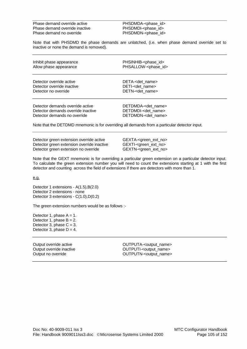
Doc No: 40-9009-011 Iss 3 MTC Configurator Handbook
File: Handbook 9009011Iss3.doc Microsense Systems Limited 2000 Page 105 of 152
Phase demand override active PHSDMDA-<phase_id> Phase demand override inactive PHSDMDI-<phase_id> Phase demand no override PHSDMDN-<phase_id> Note that with PHSDMD the phase demands are unlatched, (i.e. when phase demand override set to inactive or none the demand is removed).
Inhibit phase appearance PHSINHIB-<phase_id> Allow phase appearance PHSALLOW-<phase_id>
Detector override active DETA-<det_name> Detector override inactive DETI-<det_name> Detector no override DETN-<det_name>
Detector demands override active DETDMDA-<det_name> Detector demands override inactive DETDMDI-<det_name> Detector demands no override DETDMDN-<det_name> Note that the DETDMD mnemonic is for overriding all demands from a particular detector input.
Detector green extension override active GEXTA-<green_ext_no> Detector green extension override inactive GEXTI-<green_ext_no> Detector green extension no override GEXTN-<green_ext_no> Note that the GEXT mnemonic is for overriding a particular green extension on a particular detector input. To calculate the green extension number you will need to count the extensions starting at 1 with the first detector and counting across the field of extensions if there are detectors with more than 1. e.g. Detector 1 extensions - A(1.5),B(2.0) Detector 2 extensions - none Detector 3 extensions - C(1.0),D(0.2) The green extension numbers would be as follows :- Detector 1, phase A = 1. Detector 1, phase B = 2. Detector 3, phase C = 3. Detector 3, phase D = 4.
Output override active OUTPUTA-<output_name> Output override inactive OUTPUTI-<output_name> Output no override OUTPUTN-<output_name>

MTC Configurator Handbook Doc No: 40-9009-011 Iss 3
Page 106 of 152 Microsense Systems Limited 2000 File: Handbook 9009011Iss3.doc
Serial output override active SERIALOPA-<output_name> Serial output override inactive SERIALOPI-<output_name> Serial output no override SERIALOPN-<output_name> Note that the above mnemonics are only for use with a serial UTC interface.
Switched sign request override active SWSIGNA-<sign_no> Switched sign request override inactive SWSIGNI-<sign_no> Switched sign request no override SWSIGNN-<sign_no>
UTC control bit override active UTCBITA-<bit_name> UTC control bit override inactive UTCBITI-<bit_name> UTC control bit no override UTCBITN-<bit_name>
Special conditioning fault on SCFLTON-<fault_no> Special conditioning fault off SCFLTOFF-<fault_no> Special conditioning flag on SCFLGON-<flag_no> (1-256) Special conditioning flag off SCFLGOFF-<flag_no> Note that special conditioning flags are just scratch pad bits for use in writing special conditioning statements. They can only have a true or false value.
Start special conditioning timer SCTSTART-<timer_name> Stop special conditioning timer SCTSTOP-<timer_name>
Inhibit MOVA mode MOVAINHIB Allow MOVA mode MOVAALLOW
Inhibit LRT mode LRTINHIB-<stream> Allow LRT mode LRTALLOW-<stream> LRT event override LRTEVOVR-<phase_id>.<event> Note that for LRT event enter P for prepare, D for demand, S for stopline and E for exit.
Intergreen extension override active IGEXTA-<ig_ext_no> Intergreen extension override inactive IGEXTI-<ig_ext_no> Intergreen extension no override IGEXTN-<ig_ext_no> Note that intergreen extensions are sorted by the compiler into a fixed order, indexed by detector/from phase/to phase. The easiest way to calculate the number required is to have entered the intergreen extensions in the above mentioned order, then the index number from the intergreen extension screen may be used. Another way is to blow the Configuration PROM first and step through the intergreen extensions using the IGX handset command, (start counting from 1). It should be noted that detectors will have been numbered for indexing in the order that they appear in the Detector data area.
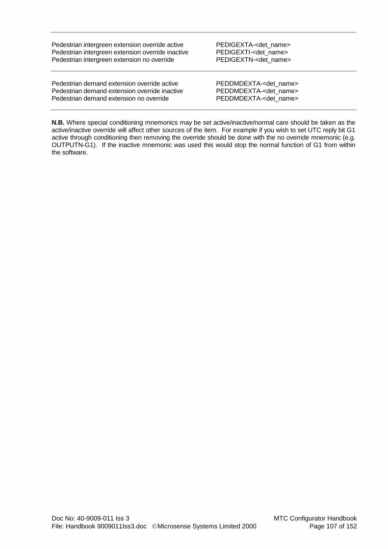
Doc No: 40-9009-011 Iss 3 MTC Configurator Handbook
File: Handbook 9009011Iss3.doc Microsense Systems Limited 2000 Page 107 of 152
Pedestrian intergreen extension override active PEDIGEXTA-<det_name> Pedestrian intergreen extension override inactive PEDIGEXTI-<det_name> Pedestrian intergreen extension no override PEDIGEXTN-<det_name>
Pedestrian demand extension override active PEDDMDEXTA-<det_name> Pedestrian demand extension override inactive PEDDMDEXTA-<det_name> Pedestrian demand extension no override PEDDMDEXTA-<det_name>
N.B. Where special conditioning mnemonics may be set active/inactive/normal care should be taken as the active/inactive override will affect other sources of the item. For example if you wish to set UTC reply bit G1 active through conditioning then removing the override should be done with the no override mnemonic (e.g. OUTPUTN-G1). If the inactive mnemonic was used this would stop the normal function of G1 from within the software.

MTC Configurator Handbook Doc No: 40-9009-011 Iss 3
Page 108 of 152 Microsense Systems Limited 2000 File: Handbook 9009011Iss3.doc
4.26.2 Screen 2
4.26.2.1 General
This screen is used to define up to 256 special conditioning timers. Use the button on the toolbar or the add item menu option to add a special conditioning timer.
4.26.2.2 Name
Timers are referenced in special conditioning statements by their timer names. A default name is provided upon creation but any combination of up to 6 alphanumeric characters may be used, preferably a name that indicates the function of the timer, (e.g. DLY1 - delay timer 1).
4.26.2.3 Duration
The timer duration must be in the range of 0 to 999.9 seconds in 0.1 second steps for TR0141A format configurations. For TR0141C format configurations the range 0 to 6000 seconds in steps of 0.1 seconds must be used.
4.26.2.4 Comments
The comments field is used to describe the function of the timer and is for printout purposes only. Up to 90 characters are allowed.
4.26.2.5 Fixed (TR0141C Format Configurations Only)
Alteration of timer settings from the handset can be prevented by marking the timer as fixed. Enter Y for a
fixed duration timer or N to allow changes.

Doc No: 40-9009-011 Iss 3 MTC Configurator Handbook
File: Handbook 9009011Iss3.doc Microsense Systems Limited 2000 Page 109 of 152
4.26.3 Screen 3
4.26.3.1 General
This screen is used to define up to 256 special conditioning faults. Use the button on the toolbar or the add item menu option to add a special conditioning fault. Faults are referenced in special conditioning statements by their numbers. For each fault required enter a
Y against the streams to be shutdown by this fault and N against the streams that are not. When a special conditioning fault is set active the appropriate streams will be shutdown and an entry will be made in the fault log.
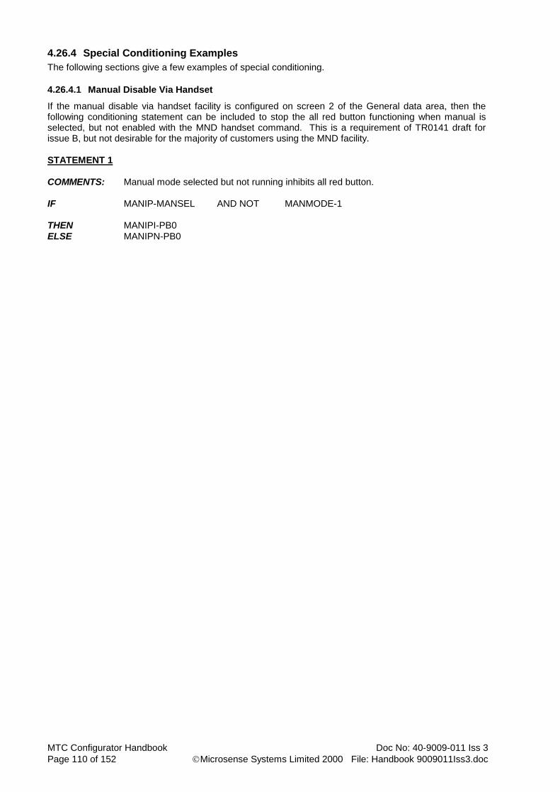
MTC Configurator Handbook Doc No: 40-9009-011 Iss 3
Page 110 of 152 Microsense Systems Limited 2000 File: Handbook 9009011Iss3.doc
4.26.4 Special Conditioning Examples
The following sections give a few examples of special conditioning.
4.26.4.1 Manual Disable Via Handset
If the manual disable via handset facility is configured on screen 2 of the General data area, then the following conditioning statement can be included to stop the all red button functioning when manual is selected, but not enabled with the MND handset command. This is a requirement of TR0141 draft for issue B, but not desirable for the majority of customers using the MND facility.
STATEMENT 1 COMMENTS: Manual mode selected but not running inhibits all red button. IF MANIP-MANSEL AND NOT MANMODE-1 THEN MANIPI-PB0 ELSE MANIPN-PB0

Doc No: 40-9009-011 Iss 3 MTC Configurator Handbook
File: Handbook 9009011Iss3.doc Microsense Systems Limited 2000 Page 111 of 152
4.26.4.2 Phase Not Extending a Particular Stage
The following example shows phase B extensions being prevented during stage 2 on stream 1.
STATEMENT 1 COMMENTS: Prevent extB during stage 2. IF CURSTG-1.2 AND NXTSTG-1.2 THEN EXTI-B ELSE EXTN-B

MTC Configurator Handbook Doc No: 40-9009-011 Iss 3
Page 112 of 152 Microsense Systems Limited 2000 File: Handbook 9009011Iss3.doc
4.26.4.3 Detector Only Demands During a Particular Stage
The following example shows how we get a detector named FX1 to insert a latched demand for phase F only whilst moving to or in stage 3 in stream 2.
STATEMENT 1 COMMENTS: FX1 inserts latched demand for F if next stage is 3. IF FDET-FX1 AND NXTSTG-2.3 THEN LPHSDMD-F ELSE

Doc No: 40-9009-011 Iss 3 MTC Configurator Handbook
File: Handbook 9009011Iss3.doc Microsense Systems Limited 2000 Page 113 of 152
4.26.4.4 Disable Manual Mode Until Handset Plugged In
The following example shows how we disable Manual mode unless a handset is plugged in, for a 2 stream controller.
STATEMENT 1 COMMENTS: Disable MAN mode unless handset plugged in. IF NOT HSCON THEN MANINHIB-1 MANINHIB-2 ELSE MANALLOW-1 MANALLOW-2

MTC Configurator Handbook Doc No: 40-9009-011 Iss 3
Page 114 of 152 Microsense Systems Limited 2000 File: Handbook 9009011Iss3.doc
4.26.4.5 Stage Inhibit Unless Certain Demands Present
The following example shows stage 4, stream 1 being inhibited, in VA mode only, unless there is a demand for either phase G or J.
STATEMENT 1 COMMENTS: In VA mode inhibit stage 1.4 if no demG+J. IF PHSDMD-G OR PHSDMD-J NOT AND VAMODE-1 THEN STGINHIB-1.4 ELSE STGALLOW-1.4

Doc No: 40-9009-011 Iss 3 MTC Configurator Handbook
File: Handbook 9009011Iss3.doc Microsense Systems Limited 2000 Page 115 of 152
4.26.4.6 Pedestrian Link (TR0141A Format Configurations Only)
The following example shows the statements required to provide a Pedestrian Link. Note that 3 timers are required for each link and these must be specified on screen 2 of the Special Conditioning data area. In this example OVR1 is the override timer, DLY1 is the delay timer and WIN1 is the window timer, (inhibit release period). The example pedestrian link uses output 16, (named LINK1 in the Input/Output data area) to provide an inhibit link to an adjacent controller. Lifting of the inhibit is triggered by phase B terminating. Note that the inhibit is also removed if the signals are off, either manually or due to a fault log entry. To get the output short circuit for inhibit output 16 must have an invert state of OFF in the Input/Output data area.
STATEMENT 1 COMMENTS: Phase B stopping starts DLY1 timer. IF STOPNG-B THEN SCTSTART-DLY1 ELSE
STATEMENT 2 COMMENTS: DLY1 or OVR1 timer expired starts WIN1 timer. IF SCTEXPRD-DLY1 OR SCTEXPRD-OVR1 THEN SCTSTART-WIN1 ELSE
STATEMENT 3 COMMENTS: WIN1 timer expired starts OVR1 timer. IF SCTEXPRD-WIN1 THEN SCTSTART-OVR1 ELSE
STATEMENT 4 COMMENTS: SHD/MSD mode or WIN1 timer running removes output LINK1, else sets it. IF SHDMODE-1 OR MSDMODE-1 OR SCTRUNNG-WIN1 THEN OUTPUTN-LINK1 ELSE OUTPUTA-LINK1

MTC Configurator Handbook Doc No: 40-9009-011 Iss 3
Page 116 of 152 Microsense Systems Limited 2000 File: Handbook 9009011Iss3.doc
4.26.4.7 SD/SA
The following example shows the statements required to provide standard SD/SA working on phase A, (extra clearance on request from SD/SA logic or during Fixed Time mode). Note that there are 3 inputs required from each SD/SA logic unit, called GERQA, ECPRQA and FLTA. These must be configured in the Detector and Input/Output data areas as follows :- GERQA must be type NM, OC active and extends A for 0 secs. ECPRQA must be type NM and OC active. FLTA must be type NM, OC active and have a DFM active duration of 1 minute. In addition to the above three inputs we also require a dummy detector input, (type DD) called IGEXTA. Screen 2 of the Intergreen data area, (Maximum Intergreen Durations) must be filled in for the SD/SA phase. Where the phase has an intergreen to another phase this requires a value of normal intergreen + extra clearance period required. The Intergreen Extension data area must then be completed to give an extension for each of maximum intergreens entered with the associated detector as IGEXTA and a 0 second extension time. e.g. A - C - IGEXTA - 0 secs It should be noted that 1 set of SD/SA logic and SMIF equipment is required for each phase using double SD or SA and 2 sets are required for each phase using triple SD, (1 for the outer loops and 1 for the inner loops).
STATEMENT 1 COMMENTS: ECPRQA active or MFT mode during phase A L/A then set IGEXTA. IF FDET-ECPRQA OR MFTMODE-1 AND STOPNG-A THEN DETA-IGEXTA ELSE
STATEMENT 2 COMMENTS: Phase A green removes IGEXTA. IF PHASE-A THEN DETN-IGEXTA ELSE
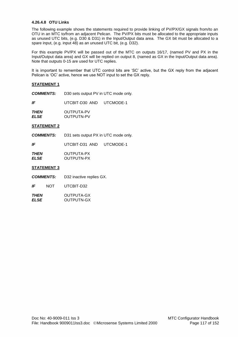
Doc No: 40-9009-011 Iss 3 MTC Configurator Handbook
File: Handbook 9009011Iss3.doc Microsense Systems Limited 2000 Page 117 of 152
4.26.4.8 OTU Links
The following example shows the statements required to provide linking of PV/PX/GX signals from/to an OTU in an MTC to/from an adjacent Pelican. The PV/PX bits must be allocated to the appropriate inputs as unused UTC bits, (e.g. D30 & D31) in the Input/Output data area. The GX bit must be allocated to a spare input, (e.g. input 48) as an unused UTC bit, (e.g. D32). For this example PV/PX will be passed out of the MTC on outputs 16/17, (named PV and PX in the Input/Output data area) and GX will be replied on output 8, (named as GX in the Input/Output data area). Note that outputs 0-15 are used for UTC replies. It is important to remember that UTC control bits are ‘SC’ active, but the GX reply from the adjacent Pelican is ‘OC’ active, hence we use NOT input to set the GX reply.
STATEMENT 1 COMMENTS: D30 sets output PV in UTC mode only. IF UTCBIT-D30 AND UTCMODE-1 THEN OUTPUTA-PV ELSE OUTPUTN-PV
STATEMENT 2 COMMENTS: D31 sets output PX in UTC mode only. IF UTCBIT-D31 AND UTCMODE-1 THEN OUTPUTA-PX ELSE OUTPUTN-PX
STATEMENT 3 COMMENTS: D32 inactive replies GX. IF NOT UTCBIT-D32 THEN OUTPUTA-GX ELSE OUTPUTN-GX

MTC Configurator Handbook Doc No: 40-9009-011 Iss 3
Page 118 of 152 Microsense Systems Limited 2000 File: Handbook 9009011Iss3.doc
4.27 Red Lamp Monitoring Data Area
There are three screens in this data area, none of which have any items.
4.27.1 Screen 1
4.27.1.1 General
This screen is used to define red lamp monitoring data either for the Microsense add-on LMU(R) or for a
third party add-on unit. Use the button on the toolbar or the add item menu option to add a Microsense RLMU, (up to 4 available). Note that when using the Microsense integral lamp monitor, (ILM) do not enter any data on this screen, only on the next two.
4.27.1.2 Auto Clear Red Lamp Warnings
The auto-clear red lamp warnings function is selected by the adjacent check box. The default is not selected, but selected is probably the most desirable, as this removes the need for an engineer with a handset on site when faulty red lamps are being replaced. Note that this option field is the same as the one that appears in the Integral Lamp Monitoring data area.
4.27.1.3 RLMU Type Is Microsense (TR0141A Format Configurations Only)
RLMU type is Microsense is selected by the adjacent check box. This option should be selected when using the Microsense add-on LMU(R) unit, (this is the default). If using an ILM then it does not matter what is selected here.

Doc No: 40-9009-011 Iss 3 MTC Configurator Handbook
File: Handbook 9009011Iss3.doc Microsense Systems Limited 2000 Page 119 of 152
4.27.1.4 MSL RLMUs (TR0141A Format Configurations Only)
For Microsense RLMUs enter the phases being monitored against the appropriate RLMU channels. Refer to the Microsense RLMU Handbook for details of channel allocation, (doc no. 40-9120-003). This is not shown for TR0141C format configurations as the Microsense RMLU serial connection is not supported by TR0141C controller firmware (C24090010xx issue 12 or later) as the serial port is now used for serial UTC information.
4.27.1.5 Other RLMUs
For other RLMUs, (1 required per stage stream) enter the appropriate input names for the single and multiple red lamp failure signals. Note that the input names used here are displayed in the Input/Output data area. N.B. For TR0141C configurations Microsense RLMUs are considered in this category.

MTC Configurator Handbook Doc No: 40-9009-011 Iss 3
Page 120 of 152 Microsense Systems Limited 2000 File: Handbook 9009011Iss3.doc
4.27.2 Screen 2
4.27.2.1 General
This screen is used to define stage stream related red lamp monitoring data and must be filled in for add-on RLMUs, (Microsense or third-party) and ILM.
4.27.2.2 Red Fault Extension Period
The red fault extension period must be in the range of 0 to 300 seconds in 0.1 second steps. This period is an all red extension given on moves to a stage with a pedestrian phase when a single red lamp failure exists.
4.27.2.3 Shutdown On Streams
For shutdown on streams enter a Y against each stream that is to be shutdown when a multiple red lamp failure exists. For streams that are not to be shutdown or do not have red lamp monitoring leave as N, (default). Shutdown of streams is normally only used on Part-Time junctions, as it is not currently approved for sites with pedestrian phases in the UK.
4.27.2.4 Inhibited Stages
For inhibited stages enter the stage(s) to be inhibited when a multiple red lamp failure exists on the associated stream. Stage numbers must be in the range of 0 to 15 and must be separated by commas. Inhibited stages are normally only used on junctions with exclusive pedestrian phases and audibles.

Doc No: 40-9009-011 Iss 3 MTC Configurator Handbook
File: Handbook 9009011Iss3.doc Microsense Systems Limited 2000 Page 121 of 152
4.27.3 Screen 3
4.27.3.1 General
This screen is used to define phase related red lamp monitoring data and must be filled in for add-on RLMUs, (Microsense or third-party) and ILM.
4.27.3.2 Phases Inhibited By A Second Red Failure
For phases inhibited by a second red failure enter the phase(s) to be inhibited by the index phase when it has a multiple red lamp failure, (i.e. data only entered against vehicle phases with a red aspect that conflict with pedestrian phases). Note that multiple phase id’s must be separated by commas. This data is normally only specified for junctions with audible/tactile pedestrian facilities. When a multiple red lamp failure occurs the phase(s) specified for inhibit also have their wait indicator lit, (amber drive) if they are pedestrian phases.
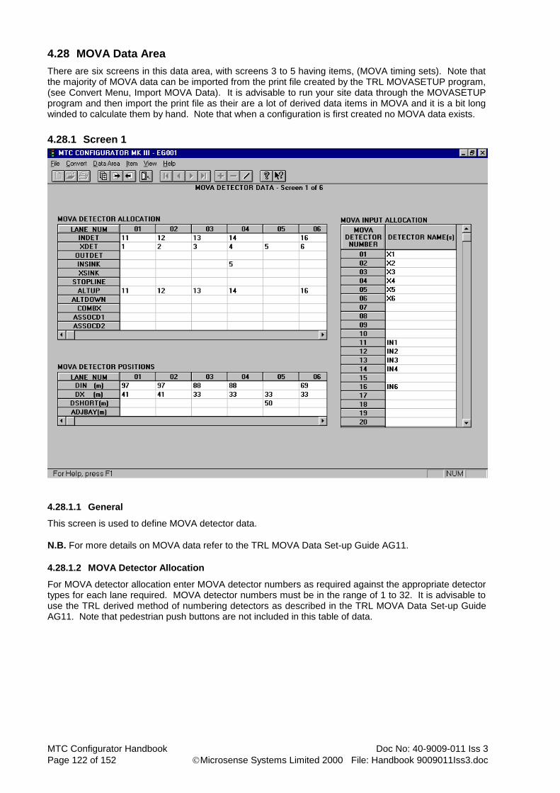
MTC Configurator Handbook Doc No: 40-9009-011 Iss 3
Page 122 of 152 Microsense Systems Limited 2000 File: Handbook 9009011Iss3.doc
4.28 MOVA Data Area
There are six screens in this data area, with screens 3 to 5 having items, (MOVA timing sets). Note that the majority of MOVA data can be imported from the print file created by the TRL MOVASETUP program, (see Convert Menu, Import MOVA Data). It is advisable to run your site data through the MOVASETUP program and then import the print file as their are a lot of derived data items in MOVA and it is a bit long winded to calculate them by hand. Note that when a configuration is first created no MOVA data exists.
4.28.1 Screen 1
4.28.1.1 General
This screen is used to define MOVA detector data.
N.B. For more details on MOVA data refer to the TRL MOVA Data Set-up Guide AG11.
4.28.1.2 MOVA Detector Allocation
For MOVA detector allocation enter MOVA detector numbers as required against the appropriate detector types for each lane required. MOVA detector numbers must be in the range of 1 to 32. It is advisable to use the TRL derived method of numbering detectors as described in the TRL MOVA Data Set-up Guide AG11. Note that pedestrian push buttons are not included in this table of data.

Doc No: 40-9009-011 Iss 3 MTC Configurator Handbook
File: Handbook 9009011Iss3.doc Microsense Systems Limited 2000 Page 123 of 152
4.28.1.3 MOVA Input Allocation
For MOVA input allocation enter the required detector name(s) against the appropriate MOVA detector numbers. Where multiple detector names are being specified these must be separated by commas. Note that all detector names entered here must have been previously specified in the Detector data area. This data provides a mapping of controller detector names to MOVA detector numbers. Where pedestrian links are required the relevant push button input names must be specified against spare MOVA detector channels. Where a COMBX-detector is being used enter the MTC names for the appropriate lanes X-detector and the associated X-detector(s).
4.28.1.4 MOVA Detector Positions
For MOVA detector positions enter the distance from the stop-line to the IN and X loops in metres. Also enter the length of any short lanes or adjacent bays in metres. Note that this data is currently for printout purposes only.

MTC Configurator Handbook Doc No: 40-9009-011 Iss 3
Page 124 of 152 Microsense Systems Limited 2000 File: Handbook 9009011Iss3.doc
4.28.2 Screen 2
4.28.2.1 General
This screen is used to define general MOVA link data. Note that screen 3 defines more link data. In the following field descriptions the upper case names in ( ) refer to the TRL data item name.
N.B. For more details on MOVA data refer to the TRL MOVA Data Set-up Guide AG11.
4.28.2.2 Link Type
For link type, (LTYPE) enter T for a traffic link or P for a pedestrian link. Unused links should be left blank and used links must be contiguous.
4.28.2.3 Assoc P/B
For associated push button enter the MOVA detector number, (1 to 32) for the associated pedestrian push button(s), as defined on screen 1, for each pedestrian link. Leave blank for traffic links.
4.28.2.4 Assoc Phases
For associated phases enter the phase id(s) associated with each link used. Note that multiple phase id’s must be separated by commas. Real or dummy phases may be specified.
4.28.2.5 Assoc Lanes
For associated lanes, (LLANES) enter the required lane number(s) for each link used. Note that multiple lane numbers, (maximum of 3 allowed) must be separated by commas.
4.28.2.6 Short Link
For short link, (SHORTL) enter either Y if the link is short or N if it is not. The definition of a short link is one that only has short lane without any IN-detectors.
Doc No: 40-9009-011 Iss 3 MTC Configurator Handbook
File: Handbook 9009011Iss3.doc Microsense Systems Limited 2000 Page 125 of 152
4.28.2.7 Num Main Lanes
For number of main lanes, (NMAINL) enter the number of main lanes on each traffic link, (1 to 3). This is the number of long lanes, (those with IN-detectors) or if this is a short link then the number of short lanes.
4.28.2.8 LGREEN1 To LGREEN8
For LGREEN1 to LGREEN8 enter the required link green values for each link/stage used. LGREENs must be in the range of 0 to 4, (see TRL MOVA Data Set-up Guide AG11 for definition of each value). Note that a blank entry is taken as 0 and the stage numbers referred to are MOVA stage numbers not MTC stage numbers, although they may be the same, (see screen 5 for more details).

MTC Configurator Handbook Doc No: 40-9009-011 Iss 3
Page 126 of 152 Microsense Systems Limited 2000 File: Handbook 9009011Iss3.doc
4.28.3 Screen 3
4.28.3.1 General
This screen is used to define the MOVA link data contained in the MOVA timing sets, (i.e. can be changed by the timetable). Note that there are 4 MOVA timing sets, each of which is an item of this screen.
N.B. For more details on MOVA data refer to the TRL MOVA Data Set-up Guide AG11.
4.28.3.2 LMIN
For LMIN, (link minimum green time) enter a value in the range of 1 to 25 seconds in 1 second steps.
4.28.3.3 ESLMAX
For ESLMAX, (link end of saturation time) enter a value in the range of 1 to 120 seconds in 1 second steps.
4.28.3.4 LOSTIM
For LOSTIM, (link lost time) enter a value in the range of 1 to 64 seconds in 1 second steps.
4.28.3.5 STOPEN
For STOPEN, (link stop penalty) enter a value in the range of 0 to 65 seconds in 1 second steps.
4.28.3.6 BONTIM
For BONTIM, (link bonus green recalculation time) enter a value in the range of 0 to 60 seconds in 1 second steps.

Doc No: 40-9009-011 Iss 3 MTC Configurator Handbook
File: Handbook 9009011Iss3.doc Microsense Systems Limited 2000 Page 127 of 152
4.28.3.7 BONCUT
For BONCUT, (marker to indicate if bonus situation is allowed to cut maximum green times short, by switching to short-cycle operation) enter a value in the range of 0, 1 or -1 to -12.
4.28.3.8 MIXOUT
For MIXOUT, (minimum no. of vehicles between X and OUT detectors to demand an early cut-off) enter a value in the range of -99 to 99.
4.28.3.9 SDCODE1 To SDCODE8
For SDCODE1 to SDCODE8, (link stage demand codes) enter one of the following values: 0, 1, 2, 1X, 2X, 3X, 1XY, 2XY or 3XY where X and Y are MOVA stage numbers in the range of 1 to 8. Note that a blank entry is taken as 0.

MTC Configurator Handbook Doc No: 40-9009-011 Iss 3
Page 128 of 152 Microsense Systems Limited 2000 File: Handbook 9009011Iss3.doc
4.28.4 Screen 4
Left Hand View

Doc No: 40-9009-011 Iss 3 MTC Configurator Handbook
File: Handbook 9009011Iss3.doc Microsense Systems Limited 2000 Page 129 of 152
Right Hand View
4.28.4.1 General
This screen is used to define MOVA lane data all of which is contained in the MOVA timing sets, (i.e. can be changed by the timetable). Note that there are 4 MOVA timing sets, each of which is an item of this screen.
N.B. For more details on MOVA data refer to the TRL MOVA Data Set-up Guide AG11.
4.28.4.2 CSPEED
For CSPEED, (lane cruise speed) enter a value in the range of 5 to 25 metres per second in 1 m/s steps. Note that this data is currently for printout purposes only.
4.28.4.3 SATINC
For SATINC, (time increment between vehicles discharging at saturation flow) enter a value in the range of 1.5 to 3 seconds in 0.1 second steps. This value is commonly in the range of 1.8 to 2.5 seconds.
4.28.4.4 STLOST
For STLOST, (lane start-up lost time) enter a value in the range of 0 to 5 seconds in 0.1 second steps. The typical value is 1.3 seconds.
4.28.4.5 COMTIM
For COMTIM, (time after which to use combination X detector) enter a value in the range of 0 to 50 seconds in 1 second steps. This data is only applicable for lanes with combination X-detectors.
MTC Configurator Handbook Doc No: 40-9009-011 Iss 3
Page 130 of 152 Microsense Systems Limited 2000 File: Handbook 9009011Iss3.doc
4.28.4.6 LANEWF
For LANEWF, (lane weighting factor) enter a value in the range of 1 to 16 in steps of 1. Note that the total of all lane weighting factors must not exceed 64. The typical value is 1.
4.28.4.7 BONBC
For BONBC, (bonus base count for a long lane) enter a value in the range of 1 to 50 vehicles in 1 vehicle steps. Note that this data is only applicable for lanes on links using bonus green times.
4.28.4.8 MAXMIN
For MAXMIN, (maximum minimum-green time) enter a value in the range of 1 to 25 seconds in 0.5 second steps.
4.28.4.9 CRUSIN
For CRUSIN, (cruise time from IN-detector to stop-line) enter a value in the range of 1 to 10 seconds in 0.5 second steps.
4.28.4.10 CRUSX
For CRUSX, (cruise time from X-detector to stop-line) enter a value in the range of 1 to 6 seconds in 0.5 second steps.
4.28.4.11 MOVQIN
For MOVQIN, (moving queue over IN-detector time) enter a value in the range of 10 to 70 seconds in 0.5 second steps.
4.28.4.12 MOVQX
For MOVQX, (moving queue over X-detector time) enter a value in the range of 10 to 40 seconds in 0.5 second steps.
4.28.4.13 QMINON
For QMINON, (minimum ‘on’ time for a detector to indicate a queue) enter a value in the range of 2 to 20 seconds in 1 second steps. The typical value is 6 seconds.
4.28.4.14 XOSAT
For XOSAT, (marker to indicate that X-detector may be used to check for oversaturation) enter a value in the range of 0 to 2 in steps of 1.
4.28.4.15 OSATCC
For OSATCC, (lane oversaturation critical vehicle count) enter a value in the range of 1 to 20 vehicles in 1 vehicle steps.
4.28.4.16 GAMBER
For GAMBER, (amber time used as effective green) enter a value in the range of 0.5 to 3 seconds in 0.5 second steps.
4.28.4.17 SATGAP
For SATGAP, (saturation flow gap) enter a value in the range of 1 to 2 seconds in 0.1 second steps.
4.28.4.18 CRITG
For CRITG, (critical gap for a single lane) enter a value in the range of 2 to 5 seconds in 0.1 second steps. Note that this value is SATGAP + 2.

Doc No: 40-9009-011 Iss 3 MTC Configurator Handbook
File: Handbook 9009011Iss3.doc Microsense Systems Limited 2000 Page 131 of 152
4.28.5 Screen 5
4.28.5.1 General
This screen is used to define MOVA stage data all of which is contained in the MOVA timing sets, (i.e. can be changed by the timetable). Note that there are 4 MOVA timing sets, each of which is an item of this screen. In the following field descriptions the upper case names in ( ) refer to the TRL data item name.
N.B. For more details on MOVA data refer to the TRL MOVA Data Set-up Guide AG11.
4.28.5.2 MTC Stage No
For the MTC stage number enter the actual MTC stage number that corresponds to the index MOVA stage number. Note that the stage numbers are usually the same, but they can be different if certain MTC stages are not required in MOVA.
4.28.5.3 Min Green
For the stage minimum green, (MIN) enter a value in the range of 1 to 25 seconds in 1 second steps.
4.28.5.4 Max Green
For the stage maximum green, (MAX) enter a value in the range of 1 to 120 seconds in 1 second steps.
4.28.5.5 Low Max Green
For the stage low maximum green, (LOWMAX) enter a value in the range of 1 to 120 seconds in 1 second steps. This value is usually set the same as the MAX.
4.28.5.6 To Stage1 - To Stage8
For the interstage times to stage1 - to stage8, (CHANGE) enter a value in the range of 0 to 20 seconds in 1 second steps or -1 for a prohibited move.
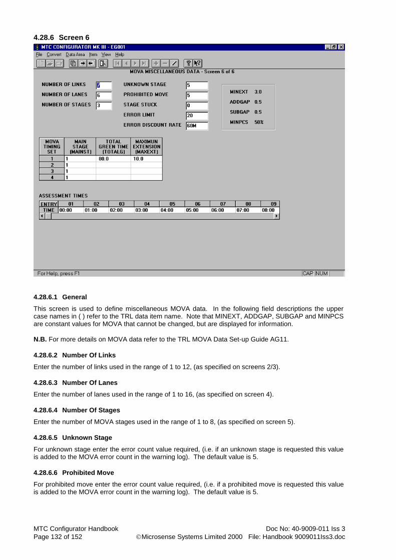
MTC Configurator Handbook Doc No: 40-9009-011 Iss 3
Page 132 of 152 Microsense Systems Limited 2000 File: Handbook 9009011Iss3.doc
4.28.6 Screen 6
4.28.6.1 General
This screen is used to define miscellaneous MOVA data. In the following field descriptions the upper case names in ( ) refer to the TRL data item name. Note that MINEXT, ADDGAP, SUBGAP and MINPCS are constant values for MOVA that cannot be changed, but are displayed for information.
N.B. For more details on MOVA data refer to the TRL MOVA Data Set-up Guide AG11.
4.28.6.2 Number Of Links
Enter the number of links used in the range of 1 to 12, (as specified on screens 2/3).
4.28.6.3 Number Of Lanes
Enter the number of lanes used in the range of 1 to 16, (as specified on screen 4).
4.28.6.4 Number Of Stages
Enter the number of MOVA stages used in the range of 1 to 8, (as specified on screen 5).
4.28.6.5 Unknown Stage
For unknown stage enter the error count value required, (i.e. if an unknown stage is requested this value is added to the MOVA error count in the warning log). The default value is 5.
4.28.6.6 Prohibited Move
For prohibited move enter the error count value required, (i.e. if a prohibited move is requested this value is added to the MOVA error count in the warning log). The default value is 5.
Doc No: 40-9009-011 Iss 3 MTC Configurator Handbook
File: Handbook 9009011Iss3.doc Microsense Systems Limited 2000 Page 133 of 152
4.28.6.7 Stage Stuck
For stage stuck enter the error count value required, (i.e. if the junction is considered to be stuck in a stage this value is added to the MOVA error count in the warning log). The default value is 2, but if the site is likely to have a low flow rate during the night-time it may be advisable to set this value to 0.
4.28.6.8 Error Limit
For error limit enter the value of MOVA error count at which the controller will drop out of MOVA mode, (i.e. if the count of MOVA errors in the warning log reaches this value then MOVA mode will be disabled and will require manual intervention to get it running again). The default value is 20.
4.28.6.9 Error Discount Rate
For error discount rate enter the period of time after which the MOVA error count in the warning log will be decremented. This value can be entered in minutes or hours by adding the appropriate suffix of M or H. The default value is 60 minutes.
4.28.6.10 Main Stage
For the main stage, (MAINST) enter a value in the range of 0 to 8, where 0 indicates no reversion required. The default value is stage 1.
4.28.6.11 Total Green Time
For the total green time, (TOTALG) enter a value in the range of 50 to 225 seconds in 1 second steps.
4.28.6.12 Maximum Extension
For the maximum extension, (MAXEXT) enter a value in the range of 1.5 to 10.5 seconds in 0.5 second steps.
4.28.6.13 Assessment Times
Assessment times should be entered in HH:MM format for a 24 hour clock. The default assessment times are every hour. The assessment times are used for creating the flow logs.

MTC Configurator Handbook Doc No: 40-9009-011 Iss 3
Page 134 of 152 Microsense Systems Limited 2000 File: Handbook 9009011Iss3.doc
4.29 LRT Mode Data Area
There are six screens in this data area, with screens 2 to 4 having items, (LRT timing sets). Note that when a configuration is first created no LRT data exists.
4.29.1 Screen 1
Left Hand View
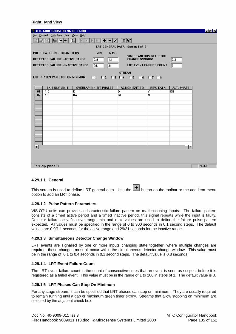
Doc No: 40-9009-011 Iss 3 MTC Configurator Handbook
File: Handbook 9009011Iss3.doc Microsense Systems Limited 2000 Page 135 of 152
Right Hand View
4.29.1.1 General
This screen is used to define LRT general data. Use the button on the toolbar or the add item menu option to add an LRT phase.
4.29.1.2 Pulse Pattern Parameters
VIS-OTU units can provide a characteristic failure pattern on malfunctioning inputs. The failure pattern consists of a timed active period and a timed inactive period, this signal repeats while the input is faulty. Detector failure active/inactive range min and max values are used to define the failure pulse pattern expected. All values must be specified in the range of 0 to 300 seconds in 0.1 second steps. The default values are 0.9/1.1 seconds for the active range and 29/31 seconds for the inactive range.
4.29.1.3 Simultaneous Detector Change Window
LRT events are signalled by one or more inputs changing state together, where multiple changes are required, those changes must all occur within the simultaneous detector change window. This value must be in the range of 0.1 to 0.4 seconds in 0.1 second steps. The default value is 0.3 seconds.
4.29.1.4 LRT Event Failure Count
The LRT event failure count is the count of consecutive times that an event is seen as suspect before it is registered as a failed event. This value must be in the range of 1 to 100 in steps of 1. The default value is 3.
4.29.1.5 LRT Phases Can Stop On Minimum
For any stage stream, it can be specified that LRT phases can stop on minimum. They are usually required to remain running until a gap or maximum green timer expiry. Streams that allow stopping on minimum are selected by the adjacent check box.

MTC Configurator Handbook Doc No: 40-9009-011 Iss 3
Page 136 of 152 Microsense Systems Limited 2000 File: Handbook 9009011Iss3.doc
4.29.1.6 Phase Id
Enter a configured phase id, (real or dummy) for each LRT phase required.
4.29.1.7 Exit Timeout
For the exit timeout enter a value in the range of 0 to 300 seconds in 0.1 second steps.
4.29.1.8 Exit Dly Limit
The exit delay limit is a handset lower limit value, (minimum threshold) for the exit event delay timer specified on the next screen. This value must be in the range of 0 to 300 seconds in 0.1 second steps.
4.29.1.9 Overlap Inhibit Phases
For overlap inhibit phases enter the phase(s) to be inhibited when the index LRT phase overlap inhibit period is running. Note that multiple phase id’s must be separated by commas.
4.29.1.10 Action Exit TO
Action exit TO defines actions to be taken when the exit timeout period expires. Valid entries are D for demand LRT phase, X for apply a permanent extension next time LRT phase runs or DX for both actions.
4.29.1.11 Rev Extn
Revertive extension indicates whether an LRT phase has a revertive extension demand or not. Enter Y for yes or N for no. If an LRT phase is terminated while an extension is active a revertive extension demand can be applied, (i.e. next time LRT phase runs it would have a permanent extension applied).
4.29.1.12 Alt Phase
When fault actions require a change to the appearance or termination of an LRT phase, this can be achieved by replacing that phase with its alternative phase. Note that both the normal and alternative phases should be configured as dummy phases with a green arrow sequence type, the signals will in these circumstances be driven by a real phase with an LRT sequence type, configured to appear and terminate in association with either of the dummies.

Doc No: 40-9009-011 Iss 3 MTC Configurator Handbook
File: Handbook 9009011Iss3.doc Microsense Systems Limited 2000 Page 137 of 152
4.29.2 Screen 2
Left Hand View

MTC Configurator Handbook Doc No: 40-9009-011 Iss 3
Page 138 of 152 Microsense Systems Limited 2000 File: Handbook 9009011Iss3.doc
Right Hand View
4.29.2.1 General
This screen is used to define general LRT timing periods and LRT phase priorities. All of this data is contained in the LRT timing sets. Note that there are 4 LRT timing sets, each of which is an item of this screen.
4.29.2.2 Timing Periods
All timing periods must be in the range of 0 to 300 seconds in 0.1 second steps.
4.29.2.3 Priority
For LRT phase priority, 1 is the highest priority down to 16 as the lowest.

Doc No: 40-9009-011 Iss 3 MTC Configurator Handbook
File: Handbook 9009011Iss3.doc Microsense Systems Limited 2000 Page 139 of 152
4.29.3 Screen 3
4.29.3.1 General
This screen is used to define prepare event sequences for the 4 available LRT timing sets. For each LRT phase requiring a prepare event up to 6 different steps can be specified. Note that the 4 LRT timing sets are each an item of this screen.
4.29.3.2 INF 1 To INF 6
The influences available for each of the six steps in the sequence, (INF 1 to INF 6) are listed below. Note that an influence is applied even if its duration is zero. HS - Hold current stage. IM - Immediate move to stage. AI - Add immediate move to stage. PX - Prevent stage moves except to stage(s). DM - Demand dependant move to stage. AD - Add demand dependant move to stage. PR - Phase request (no stage). PD - Phase demand (no stage). NL - Null Influence (no stage).
4.29.3.3 STGS 1 To STG 6
Some influences require an associated stage(s). Stage numbers must be in the range of 0 to 15. Note that multiple stage numbers must be separated by commas and stream references are not required.
4.29.3.4 Hold 1 To Hold 6
All timing periods, (HOLD 1 to HOLD 6) must be in the range of 0 to 300 seconds in 0.1 second steps.

MTC Configurator Handbook Doc No: 40-9009-011 Iss 3
Page 140 of 152 Microsense Systems Limited 2000 File: Handbook 9009011Iss3.doc
4.29.4 Screen 4
4.29.4.1 General
This screen is used to define prepare event sequences for the 4 available LRT timing sets. For each LRT phase requiring a prepare event up to 6 different steps can be specified. Note that the 4 LRT timing sets are each an item of this screen.
4.29.4.2 INF 1 To INF 6
The influences available for each of the six steps in the sequence, (INF 1 to INF 6) are listed below. Note that an influence is applied even if its duration is zero. HS - Hold current stage. IM - Immediate move to stage. AI - Add immediate move to stage. PX - Prevent stage moves except to stage(s). DM - Demand dependant move to stage. AD - Add demand dependant move to stage. PR - Phase request (no stage). PD - Phase demand (no stage). NL - Null Influence (no stage).
4.29.4.3 STGS 1 To STG 6
Some influences require an associated stage(s). Stage numbers must be in the range of 0 to 15. Note that multiple stage numbers must be separated by commas and stream references are not required.
4.29.4.4 Hold 1 To Hold 6
All timing periods, (HOLD 1 to HOLD 6) must be in the range of 0 to 300 seconds in 0.1 second steps.

Doc No: 40-9009-011 Iss 3 MTC Configurator Handbook
File: Handbook 9009011Iss3.doc Microsense Systems Limited 2000 Page 141 of 152
4.29.5 Screen 5
4.29.5.1 General
This screen is used to define the detector states required for certain LRT event triggers. Use the button on the toolbar or the add item menu option to add an LRT event.
4.29.5.2 Phase
For phase enter the normal LRT phase id, (which may be a dummy).
4.29.5.3 Event
For event type enter P for prepare, D for demand, S for stopline and E for exit.
4.29.5.4 Detectors Changed Active/Inactive
For detectors changed active/inactive enter the detector name(s) that cause the LRT event to occur. Alternative triggering events may be defined for the same event on the same phase and multiple entries can be defined for the same phase/event combination. Where multiple detector names are defined these must be separated by commas. Note that each set of detector names are ANDed together.

MTC Configurator Handbook Doc No: 40-9009-011 Iss 3
Page 142 of 152 Microsense Systems Limited 2000 File: Handbook 9009011Iss3.doc
4.29.6 Screen 6
4.29.6.1 General
This screen is used to define the failure actions used for each LRT phase. It is possible to specify a different failure action for every combination of event faults on a phase. Event types are P for prepare, D for demand, S for stopline and E for exit. The failure actions available are shown below and these may be entered directly into the failure actions table. Alternatively combinations of failure actions can be assigned to letter codes and then these letter codes can be entered into the failure actions table. Some letter code combinations are defined already. 1 - Remove inhibition of current CLF plan. (on stage stream of LRT phase). 2 - Ignore LRT phase’s events. 3 - Apply a permanent demand for the LRT phase. 4 - Apply a permanent extension for the LRT phase. 5 - Use alternative phase to replace the LRT phase. (change appearance or termination type of LRT phase). 6 - Switch off centre lamp of LRT phase signals.

Doc No: 40-9009-011 Iss 3 MTC Configurator Handbook
File: Handbook 9009011Iss3.doc Microsense Systems Limited 2000 Page 143 of 152
4.30 Integral Lamp Monitoring Data Area
There is only one screen in this data area and it does not have any items. Note that when a configuration is first created no ILM data exists.
Left Hand View

MTC Configurator Handbook Doc No: 40-9009-011 Iss 3
Page 144 of 152 Microsense Systems Limited 2000 File: Handbook 9009011Iss3.doc
Right Hand View
4.30.1 General
This screen is used to define up to 48 channels of ILM data. Use the button on the toolbar or the add item menu option to add an ILM channel.
4.30.1.1 Auto Clear Red Lamp Warnings
The auto-clear red lamp warnings function is selected by the adjacent check box. The default is not selected, but selected is probably the most desirable, as this removes the need for an engineer with a handset on site when faulty red lamps are being replaced. Note that this option field is the same as the one that appears in the Red Lamp Monitoring data area.
4.30.1.2 Unstable Toroid Indication
Unstable toroid indication when selected by the adjacent check box, means that channels with unstable toroids will be treated as though they have multiple red lamp failures, (if configured for red lamp monitoring.
4.30.1.3 Flash DFM For Lamp Conflict/Failure
The DFM lamp may be configured to flash for either lamp failures and/or lamp conflicts. These facilities are selected by their adjacent check boxes. Note that red lamp monitoring failures will flash the DFM lamp regardless of the entries made here, as these only relate to normal lamp monitoring.
4.30.1.4 Mains Unstable Indication Output(s)
For mains unstable indication output(s) enter 1 or more output names. When the mains being read by the ILM is considered to be unstable then the output(s) specified will be set. Note that output names used here must be specified in the Output data area.

Doc No: 40-9009-011 Iss 3 MTC Configurator Handbook
File: Handbook 9009011Iss3.doc Microsense Systems Limited 2000 Page 145 of 152
4.30.1.5 Name
Channel name should be a code of up to three characters to identify the channel for handset use.
4.30.1.6 Phase
Channel phase can be any configured real phase id. Note that 1 channel is required for a normal traffic or green arrow phase and 2 channels are required for a pedestrian phase, (1 for the red and green men and 1 for the wait indicators).
4.30.1.7 Aspect
Aspect indicates the colours to be monitored for each channel and is entered as a string of up to 3 characters where R = red, A = amber and G = green. Note that these characters must not be separated by anything, (e.g. RAG or RG, etc). It is advisable not to include aspects that do not have anything connected to them, (e.g. for a green arrow just enter G).
4.30.1.8 Lamp Type
For lamp type enter W for pedestrian wait lamps, L for LRT signal heads and T for anything else.
4.30.1.9 Flash
Flash must be defined as Y if the lamps can flash or N if they cannot.
4.30.1.10 Single/Multi Faults
Single/multi faults define the number of lamp failures required for the corresponding red lamp monitor fault state. Leave blank or use 0 if no red lamp monitoring required. For red lamp monitoring of normal traffic phases the values required are 1 and 2 respectively. For red lamp monitoring of LRT phases higher values may be required as each aspect consists of a number of smaller lamps.
4.30.1.11 Average Lamp Current
Average lamp current must be in the range of 30 to 440 mA in steps of 1 mA. Recommended values are 250 for lamp type T, 200 for lamp type W and 40 for lamp type L.
4.30.1.12 Failure/Conflict Indication Output(s)
Failure/conflict indication output(s) are used to define output name(s) that indicate lamp failures, (bulbs out) or lamp conflicts, (too many bulbs). These are normally UTC reply bit names and must be specified in the output data area.

MTC Configurator Handbook Doc No: 40-9009-011 Iss 3
Page 146 of 152 Microsense Systems Limited 2000 File: Handbook 9009011Iss3.doc
4.31 Input/Output Data Area Screens
There are two screens in this data area, neither of which have any items.
4.31.1 Screen 1
4.31.1.1 General
This screen is used to define up to 56 inputs, (00 to 55). Use the button on the toolbar or the add item menu option to add an input.
4.31.1.2 IP Num
Input number must be in the range 00 to 55. Note that in general if UTC is required then the control bits will be on inputs 00 to 15 and detection, pushbuttons, etc will start at input 16, but this is not essential unless OTU ribbon cables are being used.
4.31.1.3 I/F
Use this field to select the interface type, S for Serial or P for Parallel. Serial interface data is ignored by the controller if Use Serial Interface for UTC has not been checked on the UTC general data screen. For UTC control bits from a non-integral OTU and all other input types this should be left as P.
Doc No: 40-9009-011 Iss 3 MTC Configurator Handbook
File: Handbook 9009011Iss3.doc Microsense Systems Limited 2000 Page 147 of 152
4.31.1.4 Name
Input name may be up to 6 characters in length. It is important to ensure that all UTC control bits are defined on this screen. Care should be taken to ensure that the right UTC control bit names are used by referring to the UTC data area, (e.g. force bits are F01, F02, etc not F1, F2). Prefixed Names:-
Detector names will be prefixed by an * to distinguish them from UTC control bits (e.g. *DET001). Third party red lamp monitor input names will be prefixed by an $ (e.g. $SRLF1). Local link PV trigger inputs will be prefixed by an ~ (e.g. ~PHASE D).
All prefixed names can not be edited on this page and will appear in blue text.
4.31.1.5 Comment
Comments may be entered, but these are for information purposes only.

MTC Configurator Handbook Doc No: 40-9009-011 Iss 3
Page 148 of 152 Microsense Systems Limited 2000 File: Handbook 9009011Iss3.doc
4.31.2 Screen 2
4.31.2.1 General
This screen is used to define up to 24 outputs (00 to 23). Use the button on the toolbar or the add item menu option to add an output.
4.31.2.2 OP Num
Output number must be in the range 00 to 23. It is advisable to always have all 24 outputs on this screen, even if they are not being used. Note that in general if UTC is required then the reply bits will be on outputs 00 to 15 and any other outputs will start at output 16, but this is not essential unless OTU ribbon cables are being used.
4.31.2.3 Name
Output name may be up to 6 characters in length. It is important to ensure that all UTC reply bits, hurry call confirm outputs and miscellaneous outputs used by special conditioning are defined on this screen. Care should be taken to ensure that the right UTC reply bit names are used by referring to the UTC data area, (e.g. stage demand reply bits are SD01, SD02, etc not SD1, SD2).

Doc No: 40-9009-011 Iss 3 MTC Configurator Handbook
File: Handbook 9009011Iss3.doc Microsense Systems Limited 2000 Page 149 of 152
4.31.2.4 Invert
Invert state may be ON or OFF. Output numbers 00 to 15 have a default invert state of ON and 16 to 23 have a default state of OFF. The invert state combined with the links on the I/O card determine the active state of the output as follows :- With I/O card link in position ‘A’, (power down state = open circuit):- ON gives open circuit active, (default for UTC replies). OFF gives short circuit active, (default for link outputs). With I/O card link in position ‘B’, (power down state = short circuit):- ON gives short circuit active. OFF gives open circuit active.
N.B. On older I/O cards, (ones with small silver relays) the link positions are reversed, (i.e. in the above read position ‘A’ as position ‘B’ and vice-versa).
4.31.2.5 Comment
Comments may be entered, but these are for information purposes only.

MTC Configurator Handbook Doc No: 40-9009-011 Iss 3
Page 150 of 152 Microsense Systems Limited 2000 File: Handbook 9009011Iss3.doc
5. CONFIGURATOR IMPORT/EXPORT
5.1 General
At the current time importing/exporting/archiving/copying of configurations must be done from the standalone Configurator Import/Export utility. The following diagram shows the main menu for this utility.
5.2 Import
Use the import function to copy a configuration file from another destination into the system, (i.e. one that has been previously exported or archived from a Configurator. When the import option has been selected a dialogue box will be displayed for selecting the name and location of the file to import from. When a file has been selected another dialogue box will be displayed showing the configuration number, site name and issue of the configuration about to be imported along with the option to continue or cancel. If the chosen configuration already exists then a dialogue box will be displayed asking whether you wish to overwrite it or not.

Doc No: 40-9009-011 Iss 3 MTC Configurator Handbook
File: Handbook 9009011Iss3.doc Microsense Systems Limited 2000 Page 151 of 152
5.3 Export
Use the export function to copy all of the data for a particular configuration in the system out to another destination. Note that export will still leave the configuration in the system. When the export option has been selected a dialogue box will be displayed for choosing the required configuration for export. The navigator buttons should be used to move through the list of configurations. When a configuration has been selected another dialogue box will be displayed for defining the name and
location of the file to export to. A default location\file name of ‘c:\mtccfg3\xxxxx.mdb’ will be given,
(where xxxxx is the Configuration number). If the chosen file name already exists then a dialogue box will be displayed asking whether you wish to overwrite the file or not. Note that this facility is also available in the MTC Configurator’s File menu.
5.4 Archive
Use the archive function to copy all of the data for a particular configuration in the system out to another destination. Note that archive will also delete the configuration from the system. When the archive option has been selected a warning will be displayed informing you that the configuration will be deleted from the database. Continuation will cause another dialogue box to be displayed for choosing the required configuration for archive. The navigator buttons should be used to move through the list of configurations. When a configuration has been selected another dialogue box will be displayed for defining the name and
location of the file to archive to. A default location\file name of ‘c:\mtccfg3\xxxxx.mdb’ will be given,
(where xxxxx is the Configuration number). If the chosen file name already exists then a dialogue box will be displayed asking whether you wish to overwrite the file or not.
5.5 Copy
Use the copy function to copy an existing configuration in the system to another to save time editing similar configurations. When the copy option has been selected a dialogue box will be displayed for choosing the required configuration to copy. The navigator buttons should be used to move through the list of configurations. When a configuration has been selected another dialogue box will be displayed for defining the configuration number and site name to copy to. If the chosen file name already exists then a dialogue box will be displayed asking whether you wish to overwrite the it or not.
5.6 Repair & Compact
Not used normally. Would only be used under guidance from Microsense.

MTC Configurator Handbook Doc No: 40-9009-011 Iss 3
Page 152 of 152 Microsense Systems Limited 2000 File: Handbook 9009011Iss3.doc
6. PROM BLOWING
Configurations are compiled into standard Intel extended hex files, which can be used for blowing PROMs on any programmer compatible with 128K x 16-bit devices, (e.g. Intel 27C210, SGS Thomson 27C1024). Note that the device must have an access time of at least 150nS. As the Configurator operates under windows it is a good idea to create an icon/shortcut for PROM blowing. The icon can be set-up to call a windows ‘pif’ file, (in Windows 3.1 or 3.11) that in turn calls a DOS batch file to perform the prom blowing. Note that the ‘pif’ file can be set-up with optional parameters set to ? this will cause a parameter box to be displayed which can be used to enter the configuration number. With a Windows 9x system a parameter box can also be displayed by editing the properties of the shortcut and adding a ? on the end of the command line. Following is an example of the DOS batch file used at Microsense for PROM blowing using a Needham’s Electronics EMP-20 programmer, but there are other different types that maybe used, (e.g. ELAN 3000-142). This batch file would be located in the Configurator directory, (C:\MTCCFG3). @echo off if not exist c:\mtccfg3\%1.hex goto nofile copy c:\mtccfg3\%1.hex c:\emp20\promfile.hex cd\emp20 call emp20 goto end :nofile echo **** Hex File for %1 does not exist **** pause :end
N.B. When setting up the PROM programmer the following points should be noted. The PROM data start address should be set to 40,000H, the file format is extended Intel hex and unused bytes should be set to FFH. Some programmers have macro facilities that can run at start-up to set-up these items of data automatically.