![Hemispherical Resonator Gyro [Akimov; $MP-043-06]](https://static.fdocuments.net/doc/165x107/5527500b550346e1358b47b0/hemispherical-resonator-gyro-akimov-mp-043-06.jpg)
MICROSCALE THREE-DIMENSIONAL HEMISPHERICAL SHELL ... · MICROSCALE THREE-DIMENSIONAL HEMISPHERICAL...
4
MICROSCALE THREE-DIMENSIONAL HEMISPHERICAL SHELL RESONATORS FABRICATED FROM METALLIC GLASS M. Kanik, P. Bordeenithikasem and J. Schroers School of Engineering and Applied Science Yale University New Haven, CT, U.S. N. Selden and A. Desai Tanner Research Los Angeles, CA, U.S. D. Kim and R. M’Closkey Samueli School of Engineering and Applied Science University of California, Los Angeles Los Angeles, CA, U.S. Abstract— A novel use of bulk metallic glasses in microresonator applications is reported and a method for the fabrication of ultra- smooth and highly symmetric three-dimensional wineglass structures with integrated electrode structures is presented. A shell with N=2 modes at 9.393 kHz and 9.401 kHz was characterized for both mounted and unmounted (to the electrode structure) conditions. Prior to mounting, the resonator was found to have quality factors of 7800 and 6500 for the two degenerate modes. After mounting, capacitive readout of the shell structure in both the time and frequency domain showed the resonances shifted to 9.461 kHz and 9.483 kHz respectively, for the N=2 modes increasing the frequency split by 15 Hz. The quality factor was also found to be reduced with values of 5400 and 5300 respectively. This investigation demonstrates that a device such as the one reported here promises robust platforms for complete MEMS inertial sensors with low cost and simplified fabrication. I. INTRODUCTION Vibrating hemispherical shell structures have been of particular interest in the inertial sensor community with outstanding macroscale performance due to ultra-high quality factors in excess of 10 million [1]. Several techniques for creating a microscale shell resonator with low energy dissipation have been proposed. These techniques include micro scale glass blowmolding using quartz [2] and Pyrex [3], as well as the isotropic etching of silicon with the deposition of polysilicon [4]. These approaches however, are limited by the lack of a demonstrated functional electrode structure with controllable capacitive gaps. High symmetry requirements for high performance shell resonators necessitate the use of surface tension driven fabrication techniques, which act as a self-stabilizing contribution. The surface tension of viscous bulk metallic glasses (BMGs) is ~1 J/m2, an order of magnitude larger when compared to plastics and oxide glasses (~0.15 J/m2). Motivated by the high surface tension of metallic glasses combined with the ability to blow mold at relatively low temperatures (150- 400 °C), this paper explores the use of BMGs for use in microresonator applications. Previous investigations into a novel thermoplastic forming technique for fabricating 3-D metallic glass shells using differential gas pressure [5] serves as a basis for the current work. The fabrication approach in this paper allows for fabrication of ultra-smooth and highly symmetric 3-D hemispherical BMG shell resonators. Furthermore, this approach allows for the co-fabrication of an electrode transduction system for actuation and readout of the shell resonator. BMGs are high strength and highly elastic materials with unique processing opportunities [6]. When a material lacks any organized structure or systematic atomic arrangement, i.e. when it is in an amorphous state, the alloys’ strength, wear resistance, and corrosion resistance are often enhanced. Typical energy dissipation mechanisms present in crystalline metallic systems such as dislocations, grain boundaries, and associated slip planes are absent in metallic glasses [7]. As a way of overcoming inherent limitations in current microelectromechanical system (MEMS) applications, BMGs This work was supported by the DARPA Microsystems Technology Office, Microscale Rate Integrating Gyroscope (MRIG) program Figure 1. Image of a 3 mm diameter metallic glass shell resonator fabricated from platinum based metallic glass. 978-1-4799-0916-2/14/$31.00 ©2014 IEEE 9
Transcript of MICROSCALE THREE-DIMENSIONAL HEMISPHERICAL SHELL ... · MICROSCALE THREE-DIMENSIONAL HEMISPHERICAL...

MICROSCALE THREE-DIMENSIONAL HEMISPHERICAL SHELL
RESONATORS FABRICATED FROM METALLIC GLASS
M. Kanik, P. Bordeenithikasem and J. Schroers
School of Engineering and Applied Science
Yale University
New Haven, CT, U.S.
N. Selden and A. Desai
Tanner Research
Los Angeles, CA, U.S.
D. Kim and R. M’Closkey Samueli School of Engineering and Applied Science
University of California, Los Angeles
Los Angeles, CA, U.S.
Abstract— A novel use of bulk metallic glasses in microresonator
applications is reported and a method for the fabrication of ultra-
smooth and highly symmetric three-dimensional wineglass
structures with integrated electrode structures is presented. A
shell with N=2 modes at 9.393 kHz and 9.401 kHz was
characterized for both mounted and unmounted (to the electrode
structure) conditions. Prior to mounting, the resonator was found
to have quality factors of 7800 and 6500 for the two degenerate
modes. After mounting, capacitive readout of the shell structure
in both the time and frequency domain showed the resonances
shifted to 9.461 kHz and 9.483 kHz respectively, for the N=2
modes increasing the frequency split by 15 Hz. The quality factor
was also found to be reduced with values of 5400 and 5300
respectively. This investigation demonstrates that a device such
as the one reported here promises robust platforms for complete
MEMS inertial sensors with low cost and simplified fabrication.
I. INTRODUCTION
Vibrating hemispherical shell structures have been of particular interest in the inertial sensor community with outstanding macroscale performance due to ultra-high quality factors in excess of 10 million [1]. Several techniques for creating a microscale shell resonator with low energy dissipation have been proposed. These techniques include micro scale glass blowmolding using quartz [2] and Pyrex [3], as well as the isotropic etching of silicon with the deposition of polysilicon [4]. These approaches however, are limited by the lack of a demonstrated functional electrode structure with controllable capacitive gaps.
High symmetry requirements for high performance shell resonators necessitate the use of surface tension driven fabrication techniques, which act as a self-stabilizing contribution. The surface tension of viscous bulk metallic glasses (BMGs) is ~1 J/m2, an order of magnitude larger when compared to plastics and oxide glasses (~0.15 J/m2). Motivated by the high surface tension of metallic glasses combined with the ability to blow mold at relatively low temperatures (150-400 °C), this paper explores the use of BMGs for use in microresonator applications. Previous investigations into a
novel thermoplastic forming technique for fabricating 3-D metallic glass shells using differential gas pressure [5] serves as a basis for the current work. The fabrication approach in this paper allows for fabrication of ultra-smooth and highly symmetric 3-D hemispherical BMG shell resonators. Furthermore, this approach allows for the co-fabrication of an electrode transduction system for actuation and readout of the shell resonator.
BMGs are high strength and highly elastic materials with unique processing opportunities [6]. When a material lacks any organized structure or systematic atomic arrangement, i.e. when it is in an amorphous state, the alloys’ strength, wear resistance, and corrosion resistance are often enhanced. Typical energy dissipation mechanisms present in crystalline metallic systems such as dislocations, grain boundaries, and associated slip planes are absent in metallic glasses [7]. As a way of overcoming inherent limitations in current microelectromechanical system (MEMS) applications, BMGs
This work was supported by the DARPA Microsystems Technology
Office, Microscale Rate Integrating Gyroscope (MRIG) program
Figure 1. Image of a 3 mm diameter metallic glass shell resonator
fabricated from platinum based metallic glass.
978-1-4799-0916-2/14/$31.00 ©2014 IEEE 9

are an ideal candidate material with high strength and low energy dissipation. Furthermore, BMG MEMS utilize unique fabrication methods that allow CMOS post processing. Because of the unique and highly desirable attributes, BMGs have been suggested as an ideal candidate material for various MEMS applications [8, 9]
II. FABRICATION METHODS
The resonating hemispherical shells were chosen to be fabricated from Pt57.5Cu14.7Ni5.3P22.5 bulk metallic glass (Pt-BMG) based on its excellent processing ability and mechanical properties [10]. A finished hemispherical shell can be seen in Fig. 1. A summary of the fabrication process is depicted in Fig. 2. First, the master alloy is created by inductively melting high- purity constituent elements (at least 99.95%) inside a quartz tube under ~10 mTorr vacuum. The master alloy is then fluxed with anhydrous B2O3 for 1200 s at 1100 °C. The ingot is then casted into ~3 mm diameter rods using quartz molds followed by water quenching. The as-cast rod is verified to be fully amorphous using x-ray diffraction and differential scanning calorimeter.
A. BMG Sheet Rolling
Rolling of metallic glass in the supercooled liquid region (SCLR) is a suitable method for producing thin fully amorphous sheets with smooth surface finish [11, 12]. Rollers made of hardened tool steel with 16000 grit surface finish were preheated to 250 °C. A Pt-BMG rod is then fed into the rollers. Separation between the rollers is subsequently reduced with each pass until a sheet greater than 12 mm wide and roughly 100 μm thick with thickness uniformity within 1 μm over a 12 mm by 12 mm area is fabricated. The sheet is then cut into blanks of roughly 10 mm by 10 mm in dimension. The blanks are later polished in stages with the final polishing step utilizing 0.25 μm polycrystalline diamond suspension. The polished blank is then heated above the SCLR for surface tension driven smoothening. Atomic force microscopy measurements
showed .23 nm Ra on a 2 μm by 2 μm area.
B. Blow Molding
The main fabrication process involves a novel blow molding technique [5]. A conceptual schematic of the process can be seen in Fig. 3. The process begins with a pre-fabricated Schott Borofloat glass with high sphericity and a surface roughness less than 2 nm Ra. A laser ablation technique was utilized to fabricate a 320 μm hole in the center of the molds for the support stem. This mold is subsequently processed using photolithography techniques to define an electrode structure. Prior to blow molding, the mold was preheated to 275 °C with a stainless steel pin positioned in the laser-ablated hole, protruding 1 mm into the hemispherical cavity. The blank is then placed on the top surface of mold and a preheated blow molding nozzle is positioned over the blank. Once the blank’s temperature reaches 275 °C, 100 psi of UHP N2 is applied for 120 s, effectively blow molding the Pt-BMG into the mold. The system is subsequently quenched in methanol. Extra material is ground away, releasing the hemisphere. The rim is then polished up to 0.25 μm polycrystalline diamond suspension finish. The difference in thermal expansion coefficient between the glass mold and the metallic glass shell produces a symmetric gap across the structure, which allows for electrostatic excitation and capacitive readout. The final resonator is a 3 mm diameter hemispherical shell with a rim thickness of 30 μm ± 0.1 μm, which is confirmed using
Grind away excess material
Blow mold blanks into hemispherical molds
Anneal to surface smoothen
Cut sheets into blanks and polish
Roll rods into thin sheets
Cast master alloy into amorphous rods
Make master alloy from constituents
Figure 2. Schematic description of hemisphecial shell fabrication
Figure 3. Concept schematic of metallic glass hemispherical shell
resonator fabrication using blow molding. (a) Glass mold with electrodes
before blow molding (b) Pin insertion and blow molding using differential pressure (c) Metallic glass shell resonator with electrode
structure after blow molding and planarization. Inset shows natural
seperation of the BMG shell from the mold due to thermal mismatch coefficient with typical seperation of ~15 μm
10
scanning electron microscopy and has a final roughness of 43 nm Ra over 5 μm by 5 μm area.
III. EXPERIMENTAL RESULTS
This section reports the resonant properties of fabricated metallic glass hemispherical shells with non-contact characterization methods which include both a laser Doppler vibrometer and capacitive transduction. In both cases, and electrostatic actuation is employed to excite the N=2 vibratory modes and signals are analyzed in both the time and frequency domain. The frequency response of the resonator obtained from a Doppler vibrometer for both conditions is shown in Fig. 4.
A. Optical Readout
For optical transduction of the system, the resonant element is separated from the glass electrode system. The post of the resonator is clamped to a fixture. The fixture, and hence the resonator, is connected to the ground of the signal generator that provides the potential to the excitation electrode. The excitation electrode is attached to X-Y-Z manual stages to facilitate positioning the electrode in close proximity to the resonator cup lip.
A zero-mean periodic chirp signal with amplitude up to 10 V, whose power is concentrated in the frequency band of
interest, is summed with a DC offset, typically 50 V, and then applied to the excitation electrode. The test fixture and resonator are contained in a vacuum chamber that is pumped down to a few hundred μTorr. The vacuum chamber viewport passes a laser Doppler vibrometer beam that is turned 90 degrees by prisms so the beam spot can be focused on the resonator sidewall in the vicinity of the resonator lip. The subsequent motion of the electrostatically excited resonator is detected by the vibrometer. The response of the resonator as well as the excitation signals are captured with a data acquisition board and processed to generate empirical frequency response estimates. Wideband frequency responses are initially conducted to roughly locate the resonances, then, narrow band chirps are employed to give more detail of the frequency responses in a neighborhood of the resonances. Parameters such as modal frequencies and quality factors are extracted from analytical models fit to the frequency response estimates. Two prisms (evident in Fig. 5) are azimuthally placed at 45 degrees in order to facilitate accurate measurements of the N=2 modes.
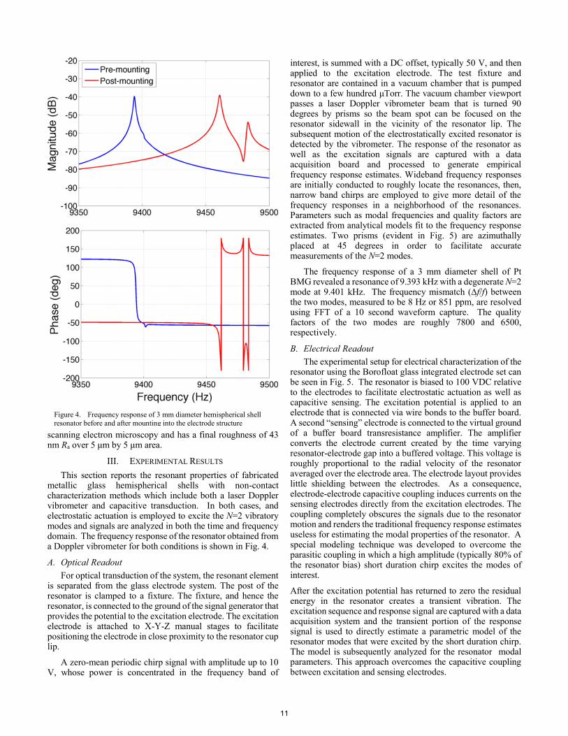
The frequency response of a 3 mm diameter shell of Pt BMG revealed a resonance of 9.393 kHz with a degenerate N=2 mode at 9.401 kHz. The frequency mismatch (∆f/f) between the two modes, measured to be 8 Hz or 851 ppm, are resolved using FFT of a 10 second waveform capture. The quality factors of the two modes are roughly 7800 and 6500, respectively.
B. Electrical Readout
The experimental setup for electrical characterization of the resonator using the Borofloat glass integrated electrode set can be seen in Fig. 5. The resonator is biased to 100 VDC relative to the electrodes to facilitate electrostatic actuation as well as capacitive sensing. The excitation potential is applied to an electrode that is connected via wire bonds to the buffer board. A second “sensing” electrode is connected to the virtual ground of a buffer board transresistance amplifier. The amplifier converts the electrode current created by the time varying resonator-electrode gap into a buffered voltage. This voltage is roughly proportional to the radial velocity of the resonator averaged over the electrode area. The electrode layout provides little shielding between the electrodes. As a consequence, electrode-electrode capacitive coupling induces currents on the sensing electrodes directly from the excitation electrodes. The coupling completely obscures the signals due to the resonator motion and renders the traditional frequency response estimates useless for estimating the modal properties of the resonator. A special modeling technique was developed to overcome the parasitic coupling in which a high amplitude (typically 80% of the resonator bias) short duration chirp excites the modes of interest.
After the excitation potential has returned to zero the residual energy in the resonator creates a transient vibration. The excitation sequence and response signal are captured with a data acquisition system and the transient portion of the response signal is used to directly estimate a parametric model of the resonator modes that were excited by the short duration chirp. The model is subsequently analyzed for the resonator modal parameters. This approach overcomes the capacitive coupling between excitation and sensing electrodes.
Figure 4. Frequency response of 3 mm diameter hemispherical shell
resonator before and after mounting into the electrode structure
11
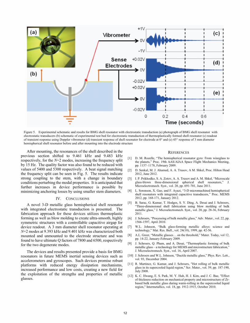
After mounting, the resonances of the shell described in the previous section shifted to 9.461 kHz and 9.483 kHz respectively, for the N=2 modes, increasing the frequency split by 15 Hz. The quality factor was also found to be reduced with values of 5400 and 5300 respectively. A beat signal matching the frequency split can be seen in Fig. 5. The results indicate strong coupling to the stem, with a change in boundary conditions perturbing the modal properties. It is anticipated that further increases in device performance is possible by minimizing anchoring losses by using smaller stem diameters.
IV. CONCLUSIONS
A novel 3-D metallic glass hemispherical shell resonator with integrated electrostatic transduction is presented. The fabrication approach for these devices utilizes thermoplastic forming as well as blow molding to create ultra-smooth, highly symmetric structures with a controllable capacitive airgap for device readout. A 3 mm diameter shell resonator operating at N=2 modes at 9.393 kHz and 9.401 kHz was characterized both mounted and unmounted to the electrode structure and was found to have ultimate Q factors of 7800 and 6500, respectively for the two degenerate modes.
The devices and results presented provide a basis for BMG resonators in future MEMS inertial sensing devices such as accelerometers and gyroscopes. Such devices promise robust platforms with reduced energy dissipation mechanisms, increased performance and low costs, creating a new field for the exploitation of the strengths and properties of metallic glasses.
REFERENCES
[1] D. M. Rozelle, “The hemispherical resonator gyro: From wineglass to the planets,” Proc. 19th AAS/AIAA Space Flight Mechanics Meeting, pp. 1157–1178, February 2009.
[2] D. Senkal, M. J. Ahamed, A. A. Trusov, A M. Shkel, Proc. Hilton Head 2012, June 2012.
[3] I. P. Prikhodko, S. A. Zotov, A. A. Trusov and A. M. Shkel, “Microscale glass-blown three-dimensional spherical shell resonators,” J. Microelectromech. Syst., vol. 20, pp. 691-701, June 2011.
[4] L. Sorenson, X. Gao, and F. Ayazi, “3-D micromachined hemispherical shell resonators with integrated capacitive transducers,” Proc. MEMS 2012, pp. 168-171, January 2012.
[5] B. Sarac, G. Kumar, T. Hodges, S. Y. Ding, A. Desai and J. Schroers, “Three-dimensional shell fabrication using blow molding of bulk metallic glass,” J. Microelectromech. Syst., vol. 20, pp. 28-36, February 2011.
[6] J. Schroers, “Processing of bulk metallic glass,” Adv. Mater., vol. 22, pp. 1566-1597, April 2010.
[7] W.L. Johnson, “Bulk glass-forming metallic alloys: science and technology,” Mat. Res. Bull., vol. 24(10), 1999, pp. 42-56.
[8] A.L. Greer, “Metallic glasses… on the threshold,” Mater. Today, vol 12, pp. 14-22, January-February 2009.
[9] J. Schroers, Q. Pham, and A. Desai, “Thermoplastic forming of bulk metallic glass – a technology for MEMS and microstructure fabrication,” J. Microelectromech. Syst., vol. 16, April 2007.
[10] J. Schroers and W.L. Johnson, “Ductile metallic glass,” Phys. Rev. Lett., vol. 93, December 2004.
[11] R. Martinez, G. Kumar, and J. Schroers, "Hot rolling of bulk metallic glass in its supercooled liquid region," Scr. Mater., vol. 59, pp. 187-190, July 2008.
[12] K. C. Hwang, E. S. Park, M. Y. Huh, H. J. Kim, and J. C. Bae, "Effect of thickness reduction on mechanical property and microstructure of Zr-based bulk metallic glass during warm-rolling in the supercooled liquid region," Intermetallics, vol. 18, pp. 1912-1915, October 2010.
Figure 5. Experimental schematic and results for BMG shell resonator with electrostatic transduction (a) photograph of BMG shell resonator with electrostatic transducers (b) schematic of experimental test bed for electrostatic transduction of thermoplastically formed shell resonator (c) readout
of transient response using Doppler vibrometer (d) transient response of shell resonator for electrode at 0° and (e) 45° response of 3 mm diameter
hemispherical shell resonator before and after mounting into the electrode structure
12