
Microring Weight Banks Control beyond 8.5-bits Accuracy
4
Letter Optics Letters 1 Microring Weight Banks Control beyond 8.5-bits Accuracy WEIPENG ZHANG 1,* ,CHAORAN HUANG 1 ,SIMON BILODEAU 1 ,AASHU J HA 1 ,ERIC BLOW 1 ,THOMAS FERREIRA DE LIMA 1 ,BHAVIN J. SHASTRI 2 , AND PAUL PRUCNAL 1 1 Department of Electrical and Computer Engineering, Princeton University, Princeton, New Jersey, 08540 1 Department of Physics, Engineering Physics and Astronomy, Queen’s University, Kingston, Ontario K7L 3N6, Canada * Corresponding author: [email protected] Compiled April 12, 2021 The microring resonators (MRR) weight bank, a ubiq- uitous element in silicon photonics providing weight addition, yet, has long suffered from the weakness of low accuracy, so that harming its potential in various promising applications. Here, we demonstrated a novel dithering method for MRR weight control, reaching an accuracy of up to 8.5 bits and a precision of up to 9.0 bits, which rivals that of the analog processors. Also, this method maintains good scalability to control multi- MRRs with little additional increase in searching time and system complexity, and has efficacious suppression to the inter-channel crosstalk. Given these features, this method could widely benefit the applications of MRR weight banks and facilitate the prevalence of the MRR in silicon photonics. © 2021 Optical Society of America http://dx.doi.org/10.1364/XX.XX.XXXXXX The MRR weight bank (MRR-WB) [1] is becoming one essen- tial building block in silicon photonics, providing individual weighting to the input light of different wavelengths. With that as a competent candidate, the MRR-WB shows up in many cutting-edge technologies, such as configuring connec- tion strength in photonics neuron networks [2–4], performing vector-matrix multiplication [5] and solving ordinary-difference equations [6, 7] in high-performance computers. The MRR-WB prevails by its advantages, including compactness, ease of tun- ing [8], high energy efficiency, and innate wavelength-division multiplexing compatibility [9, 10]. However, compared with the traditional analog computers (all-electronic implemented) [11– 13], the MRR-WB hardly offers comparative accuracy (∼ 8bits) in weight control. Hence the performance is limited in almost ev- ery scenario, such as the prediction accuracy of neuron networks [14], the usable data resolution of vector-matrix multipliers. And it is especially true in multivariate microwave photonics [15–18], where accurate weight addition is critical to guarantee sufficient sensitivity for signal analysis and separation. This accuracy weakness has long been primarily ascribed to the innate high sensitivity of the MRRs [19, 20], which para- doxically endows the MRRs the efficiency in tuning but also the difficulty in stabilizing. To overcome this incurred vulnera- bility to environmental fluctuations, the feedback scheme [10] reinforced the prior feedforward method [1], utilizing the photo- induced resonance effect [21, 22] to stabilize the resonance fre- quency. With this, both the robustness and the accuracy were effectively improved (from 3.8bits to 5.1bits). Another acknowl- edged cause of the low accuracy is the inter-channel crosstalk [1, 19], in that the closely adjacent MRRs will interfere with each other, both thermally through heat leakage, and electrically due to the common ground. This raises trouble when simultaneously controlling multiple MRRs, even if the control of a single MRR is perfectly accurate. The solution by modeling the crosstalk [19], though it becomes less effective when the number of MRRs scales up, indeed alleviates the issue for small-scaled weight banks. However, albeit these progresses, as well as the sustained improvement of the silicon photonics foundry [23, 24], the con- trol accuracy of MRR-WB seems to plateau at a limit of 5.7 bits, which no successful trial could break for years [16–18]. Rather than the MRR itself and the crosstalk, the current bot- tleneck in control accuracy might originate from other factors. To corroborate this assumption, we reviewed a recent work, which reported high accuracy of up to 7.2 bits [20]. In that work, in- stead of the commonly used signal decomposition method, the weight was evaluated by the optical power, which is insensitive to fluctuations other than the drift of the MRR resonance. For example, the efficiency variation of the Mach-Zehnder modu- lator (usually caused by polarization drift or temperature drift) could result in weight drifting but is not necessarily reflected in the output optical power. Thus, this work obtaining the high ac- curacy reveals the actual influence by the drifting sources other than the MRR-WB itself, which is paid little attention to by the prior feedback methods. In turn, a breakthrough of the MRR-WB accuracy can be envisaged if the weight drifting is monitored in the full signal path. In this letter, we introduced a novel scheme to control the MRR weight, named the dither control method, in which we im- plemented the full-path monitoring and thus achieved an accu- racy of up to 8.5 bits with good robustness. For the first time, the neuromorphic processor made by silicon photonics could have competitive programmable resolution than its counterparts, the analog computers. In the following, we demonstrated this dither control method in a 2-channel MRR-WB setup. In this setup, we experimentally examined the effectiveness of the principle, arXiv:2104.01164v2 [physics.app-ph] 9 Apr 2021
Transcript of Microring Weight Banks Control beyond 8.5-bits Accuracy

Letter Optics Letters 1
Microring Weight Banks Control beyond 8.5-bitsAccuracyWEIPENG ZHANG1,*, CHAORAN HUANG1, SIMON BILODEAU1, AASHU JHA1, ERIC BLOW1, THOMASFERREIRA DE LIMA1, BHAVIN J. SHASTRI2, AND PAUL PRUCNAL1
1Department of Electrical and Computer Engineering, Princeton University, Princeton, New Jersey, 085401Department of Physics, Engineering Physics and Astronomy, Queen’s University, Kingston, Ontario K7L 3N6, Canada*Corresponding author: [email protected]
Compiled April 12, 2021
The microring resonators (MRR) weight bank, a ubiq-uitous element in silicon photonics providing weightaddition, yet, has long suffered from the weakness oflow accuracy, so that harming its potential in variouspromising applications. Here, we demonstrated a noveldithering method for MRR weight control, reaching anaccuracy of up to 8.5 bits and a precision of up to 9.0bits, which rivals that of the analog processors. Also,this method maintains good scalability to control multi-MRRs with little additional increase in searching timeand system complexity, and has efficacious suppressionto the inter-channel crosstalk. Given these features,this method could widely benefit the applications ofMRR weight banks and facilitate the prevalence of theMRR in silicon photonics. © 2021 Optical Society of America
http://dx.doi.org/10.1364/XX.XX.XXXXXX
The MRR weight bank (MRR-WB) [1] is becoming one essen-tial building block in silicon photonics, providing individualweighting to the input light of different wavelengths. Withthat as a competent candidate, the MRR-WB shows up inmany cutting-edge technologies, such as configuring connec-tion strength in photonics neuron networks [2–4], performingvector-matrix multiplication [5] and solving ordinary-differenceequations [6, 7] in high-performance computers. The MRR-WBprevails by its advantages, including compactness, ease of tun-ing [8], high energy efficiency, and innate wavelength-divisionmultiplexing compatibility [9, 10]. However, compared with thetraditional analog computers (all-electronic implemented) [11–13], the MRR-WB hardly offers comparative accuracy (∼ 8bits)in weight control. Hence the performance is limited in almost ev-ery scenario, such as the prediction accuracy of neuron networks[14], the usable data resolution of vector-matrix multipliers. Andit is especially true in multivariate microwave photonics [15–18],where accurate weight addition is critical to guarantee sufficientsensitivity for signal analysis and separation.
This accuracy weakness has long been primarily ascribedto the innate high sensitivity of the MRRs [19, 20], which para-doxically endows the MRRs the efficiency in tuning but alsothe difficulty in stabilizing. To overcome this incurred vulnera-
bility to environmental fluctuations, the feedback scheme [10]reinforced the prior feedforward method [1], utilizing the photo-induced resonance effect [21, 22] to stabilize the resonance fre-quency. With this, both the robustness and the accuracy wereeffectively improved (from 3.8bits to 5.1bits). Another acknowl-edged cause of the low accuracy is the inter-channel crosstalk[1, 19], in that the closely adjacent MRRs will interfere with eachother, both thermally through heat leakage, and electrically dueto the common ground. This raises trouble when simultaneouslycontrolling multiple MRRs, even if the control of a single MRRis perfectly accurate. The solution by modeling the crosstalk[19], though it becomes less effective when the number of MRRsscales up, indeed alleviates the issue for small-scaled weightbanks. However, albeit these progresses, as well as the sustainedimprovement of the silicon photonics foundry [23, 24], the con-trol accuracy of MRR-WB seems to plateau at a limit of 5.7 bits,which no successful trial could break for years [16–18].
Rather than the MRR itself and the crosstalk, the current bot-tleneck in control accuracy might originate from other factors. Tocorroborate this assumption, we reviewed a recent work, whichreported high accuracy of up to 7.2 bits [20]. In that work, in-stead of the commonly used signal decomposition method, theweight was evaluated by the optical power, which is insensitiveto fluctuations other than the drift of the MRR resonance. Forexample, the efficiency variation of the Mach-Zehnder modu-lator (usually caused by polarization drift or temperature drift)could result in weight drifting but is not necessarily reflected inthe output optical power. Thus, this work obtaining the high ac-curacy reveals the actual influence by the drifting sources otherthan the MRR-WB itself, which is paid little attention to by theprior feedback methods. In turn, a breakthrough of the MRR-WBaccuracy can be envisaged if the weight drifting is monitored inthe full signal path.
In this letter, we introduced a novel scheme to control theMRR weight, named the dither control method, in which we im-plemented the full-path monitoring and thus achieved an accu-racy of up to 8.5 bits with good robustness. For the first time, theneuromorphic processor made by silicon photonics could havecompetitive programmable resolution than its counterparts, theanalog computers. In the following, we demonstrated this dithercontrol method in a 2-channel MRR-WB setup. In this setup,we experimentally examined the effectiveness of the principle,
arX
iv:2
104.
0116
4v2
[ph
ysic
s.ap
p-ph
] 9
Apr
202
1

Letter Optics Letters 2
Fig. 1. Schematic of dither MRR control. MZM, Mach-Zehnder Modulator. Ref. OSC, reference oscillator. AWG, arrayed waveguidegrating. BPD, balanced photodetector. LF, low frequency. HF, high frequency. The inlet displays the build-in bias-tee of the MZM.
demonstrated the scalability, and benchmarked the performanceof control accuracy (using the signal decomposition method).Besides, we investigated the inter-channel crosstalk issue andsearching time consumption, and prove our advantages througha comparison test.
The signal paths of a typical MRR-WB equipped system canbe found in Figure 1. Each input electrical signal was convertedonto one optical carrier (laser light of a specific frequency) bythe Mach-Zehnder modulators (MZM), then was weighted bythe corresponding MRR inside the weight bank, and lastly, a bal-anced photodetector summed all the laser lights and convertedthe processed signals back to the electrical domain. Ideally, theoffset between the MRR resonances and the laser frequenciesshould be the only factor determining the output weights. How-ever, almost every component in the signal path can fluctuatethe weight, such as the polarization drifting, the temperaturedrifting, the unstable optical alignment, etc. To address thefluctuations induced by the above non-idealities, this ditheringmethod implemented a full-path monitoring.
As shown in Figure 1, we used a MRR-WB platform consist-ing of two channels (detailed description see in Ref. [18]). Toadd the dither control into the system, we dispatched one dither-ing signal into each signal path, a pre-defined sinusoidal wave(generated by 33220A, Keysight) with frequencies usually muchlower than the input signals. These dithering signals can be sepa-rated with ease using a diplexer (ZDPLX-2150-S+, Mini-Circuits)and captured synchronously by one channel (CH1 in the Figure1) of the scope (DPO4032, Tektronix), together with the originalweighted signals (CH2). The scope was triggered by the syncoutput of the reference oscillator to align each captured wave-form of the dithering signals. As the schematic indicates, sincethe dithering signals shared the same path with the signals beingweighted, the variations of the output dithering signals couldreflect the true weight in real-time. In other words, the actualweight can be precisely controlled by supervising and stabiliz-ing the dithering signals. To introduce the dithering signals, thebuilt-in bias tee of the MZMs (see the inset of Figure 1) provideda straight-forward solution. Instead of applying DC-voltages tothe bias ports, we dithered the bias voltages at the pre-definedfrequencies, while the RF input port remained unchanged. Thus,the dither control only invaded the system with the additionof a diplexer and a reference oscillator, making it manageablefor integration into almost any silicon photonics system. When
Fig. 2. Flow chart of dither weight control procedure. int.frames, intermediate frames.
the number of channels scales up, only new dithering signalsof other harmonic frequencies need to be added to corporatewith the extra signal channels. Besides, since the frequencies ofthe dithering signals were of different harmonic orders, regard-less of the scale, we could always use just one scope channelto capture the sum of the signals (output by the diplexer) andthen digitally separate them through decomposition (which willbe explained later). Compared with the prior feedback meth-ods, there is no need for doping the MRRs and measuring theheater resistance. So the source-measure-units (SMU) can bereplaced with voltages/current sources for driving the MRRs,which reduces the cost and space, and in turn, helps with thescalability.
The operational principle of this dither control method(shown in Figure 2) goes as follows. Firstly, all the MRR aretuned to a reference position by applying predefined fixed cur-rents (iref). Meanwhile, the MZMs are dithered at the bias portin sequence that turning on only one channel at one time, andthe scope records waveforms as the reference dithering signals

Letter Optics Letters 3
for each channel. Given the sampling length of N and the totalnumber of channels M, the recorded reference signals can beexpressed as rm(t), where t = 0, ∆T, 2∆T, 3∆T, . . . , (N − 1)∆Tand m = 1, 2, . . . , M which is the index of the channel. Then areference matrix A can be constructed using all the rm(t) as itscolumns.
A = (r1(t), r2(t), · · · , rM(t))T
=
r1(0) r1(∆T) · · · r1((N − 1)∆T)
r2(0) r2(∆T) · · · r2((N − 1)∆T)
· · · · · · · · · · · ·
rM(0) rM(∆T) · · · rM((N − 1)∆T)
(1)
Next, the dithering of all the channels is turned on, and afull-range multidimensional current sweep of all channels iscarried out. The scope records frame of the dither signals ateach intermediate point in the sweep. For this procedure, eachcaptured waveform, r(t) = (r(0), r(∆T), . . . , r((N − 1)∆T)) rep-resents the addition of all the dither signals. The amplitude ofeach dither frequency can be decomposed using the Eq. 2,
W =
w1
w2
· · ·
wM
= A−1︸︷︷︸N×M
× S︸︷︷︸N×1
(2)
where A−1 is the inverse matrix of the matrix A.In the vec-tor W = (w1, w2, . . . , wM), each element wm is the correla-tion coefficient between each current dithering signal and thecorresponding reference dithering signal, namely the outputweights (if we assume the reference dithering signals representsW = (1, 1, · · · , 1)). Then, we can obtain the W − I (weight-current) curves corresponding to the applied current and theoutput weight for each channel, and establish a lookup-tableusing the curves. These curves are not reliable and precise in thelong term because of drifts, so further weight searching is neededfor accurate weight control. But it is sufficient for providinggood starting points for the weight searching. It is worth notingthat the binary searching is carried out with multi-dimensionalsearching, meaning all the channels were simultaneously con-trolled. This guarantees that the searching time would not bescaled up when the number of channels increased. This alsohelps minimize the inter-channel crosstalk, since the appliedcurrents of all the channels are under control and adjusted ifneeded to compensate for the interference during the searching.
To prove the effectiveness of the dithering control method,we evaluated the accordance between the dither signal and theactual signal. To this end, we applied a sinusoidal signal of120MHz to the RF input port as the actual signal, and ditheredthe bias port at 10MHz. After the calibration, we swept thecurrent applied to the MRR heater from 0.5 to 1.6 mA, andmeanwhile recorded the weights of the output actual signalsand the dither signals. The result shows in Figure 3(a), wherethe blue and red curves represent the weights derived from theactual the dither signal, respectively. The error between thetwo weights, the orange curve in the figure, exceeds no morethan 0.5% across the whole range, confirming that this ditheringmethod could act as an accurate sensor of the actual weight.
Next, the performance evaluation was extended to a weightbank that consists of two channels, and the result is visualized
Fig. 3. (a) Weight comparison of the actual signal and dithersignal. (b) Estimation of MRR weight bank of two channels
using a mesh-plot, as shown in Figure 3(b). This type of mesh-estimation was commonly used in previous work [19, 20], inwhich two MRR channels are tuned to equal-distant grid pointsof (w1, w2), w1,2 ∈ [−1, 1], and for each point the test repeatsmultiple times. Then, calculating the mean-valued error andthe standard derivation for all the trial results can produce theoverall accuracy and the precision of the weight control perfor-mance. Our test chose the mesh size to be 9×9, and for each grid,we repeated the weight search three times. Compared with pre-vious work, the error is significantly reduced, and an accuracyof 8.5 bits and precision of 9.0 bits are achieved, which is 2 bitsimprovement than the previous best-reported result [17], over 5bits increased than the very first reported MRR weight bank [1].
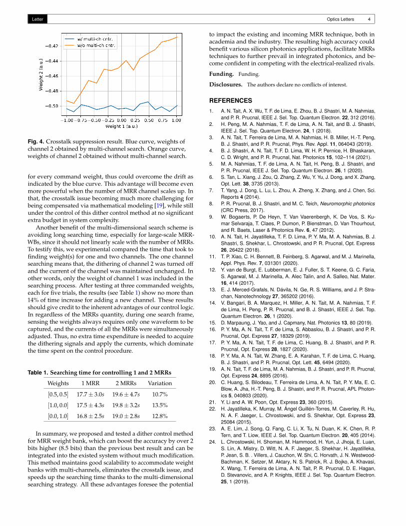
Besides the improved accuracy, we noticed the crosstalk is-sue also disappeared in our observation thanks to the multi-dimensional weight searching. To further highlight this benefit,we did a comparison test shown in Figure 4. For the experi-ment that produced the orange curve, we first tuned the weightbank to (w1, w2) = (−0.5, 0.5), then maintained the current ap-plied to channel 2 unchanged and only swept the weight ofchannel 1 using the dither weight control. In other words, weperformed a one-dimensional search in which only channel 1was in consideration. In comparison, the blue curve was ob-tained by performing the two-dimensional weight control at thesame command weights. Because of the crosstalk, when thecurrent applied to channel 1 was changed, the applied current tochannel 2 should be slightly adjusted. Otherwise, the weight ofchannel 2 would drift, which is exactly expressed by the orangecurve in the figure. In contrast, the multi-dimensional weightcontrol scheme always takes all the channels into consideration
Letter Optics Letters 4
Fig. 4. Crosstalk suppression result. Blue curve, weights ofchannel 2 obtained by multi-channel search. Orange curve,weights of channel 2 obtained without multi-channel search.
for every command weight, thus could overcome the drift asindicated by the blue curve. This advantage will become evenmore powerful when the number of MRR channel scales up. Inthat, the crosstalk issue becoming much more challenging forbeing compensated via mathematical modeling [19], while stillunder the control of this dither control method at no significantextra budget in system complexity.
Another benefit of the multi-dimensional search scheme isavoiding long searching time, especially for large-scale MRR-WBs, since it should not linearly scale with the number of MRRs.To testify this, we experimental compared the time that took tofinding weight(s) for one and two channels. The one channelsearching means that, the dithering of channel 2 was turned offand the current of the channel was maintained unchanged. Inother words, only the weight of channel 1 was included in thesearching process. After testing at three commanded weights,each for five trials, the results (see Table 1) show no more than14% of time increase for adding a new channel. These resultsshould give credit to the inherent advantages of our control logic.In regardless of the MRRs quantity, during one search frame,sensing the weights always requires only one waveform to becaptured, and the currents of all the MRRs were simultaneouslyadjusted. Thus, no extra time expenditure is needed to acquirethe dithering signals and apply the currents, which dominatethe time spent on the control procedure.
Table 1. Searching time for controlling 1 and 2 MRRs
Weights 1 MRR 2 MRRs Variation
[0.5, 0.5] 17.7± 3.0s 19.6± 4.7s 10.7%
[1.0, 0.0] 17.5± 4.3s 19.8± 3.2s 13.5%
[0.0, 1.0] 16.8± 2.5s 19.0± 2.8s 12.8%
In summary, we proposed and tested a dither control methodfor MRR weight bank, which can boost the accuracy by over 2bits higher (8.5 bits) than the previous best result and can beintegrated into the existed system without much modification.This method maintains good scalability to accommodate weightbanks with multi-channels, eliminates the crosstalk issue, andspeeds up the searching time thanks to the multi-dimensionalsearching strategy. All these advantages foresee the potential
to impact the existing and incoming MRR technique, both inacademia and the industry. The resulting high accuracy couldbenefit various silicon photonics applications, facilitate MRRstechniques to further prevail in integrated photonics, and be-come confident in competing with the electrical-realized rivals.
Funding. Funding.
Disclosures. The authors declare no conflicts of interest.
REFERENCES
1. A. N. Tait, A. X. Wu, T. F. de Lima, E. Zhou, B. J. Shastri, M. A. Nahmias,and P. R. Prucnal, IEEE J. Sel. Top. Quantum Electron. 22, 312 (2016).
2. H. Peng, M. A. Nahmias, T. F. de Lima, A. N. Tait, and B. J. Shastri,IEEE J. Sel. Top. Quantum Electron. 24, 1 (2018).
3. A. N. Tait, T. Ferreira de Lima, M. A. Nahmias, H. B. Miller, H.-T. Peng,B. J. Shastri, and P. R. Prucnal, Phys. Rev. Appl. 11, 064043 (2019).
4. B. J. Shastri, A. N. Tait, T. F. D. Lima, W. H. P. Pernice, H. Bhaskaran,C. D. Wright, and P. R. Prucnal, Nat. Photonics 15, 102–114 (2021).
5. M. A. Nahmias, T. F. de Lima, A. N. Tait, H. Peng, B. J. Shastri, andP. R. Prucnal, IEEE J. Sel. Top. Quantum Electron. 26, 1 (2020).
6. S. Tan, L. Xiang, J. Zou, Q. Zhang, Z. Wu, Y. Yu, J. Dong, and X. Zhang,Opt. Lett. 38, 3735 (2013).
7. T. Yang, J. Dong, L. Lu, L. Zhou, A. Zheng, X. Zhang, and J. Chen, Sci.Reports 4 (2014).
8. P. R. Prucnal, B. J. Shastri, and M. C. Teich, Neuromorphic photonics(CRC Press, 2017).
9. W. Bogaerts, P. De Heyn, T. Van Vaerenbergh, K. De Vos, S. Ku-mar Selvaraja, T. Claes, P. Dumon, P. Bienstman, D. Van Thourhout,and R. Baets, Laser & Photonics Rev. 6, 47 (2012).
10. A. N. Tait, H. Jayatilleka, T. F. D. Lima, P. Y. Ma, M. A. Nahmias, B. J.Shastri, S. Shekhar, L. Chrostowski, and P. R. Prucnal, Opt. Express26, 26422 (2018).
11. T. P. Xiao, C. H. Bennett, B. Feinberg, S. Agarwal, and M. J. Marinella,Appl. Phys. Rev. 7, 031301 (2020).
12. Y. van de Burgt, E. Lubberman, E. J. Fuller, S. T. Keene, G. C. Faria,S. Agarwal, M. J. Marinella, A. Alec Talin, and A. Salleo, Nat. Mater.16, 414 (2017).
13. E. J. Merced-Grafals, N. Dávila, N. Ge, R. S. Williams, and J. P. Stra-chan, Nanotechnology 27, 365202 (2016).
14. V. Bangari, B. A. Marquez, H. Miller, A. N. Tait, M. A. Nahmias, T. F.de Lima, H. Peng, P. R. Prucnal, and B. J. Shastri, IEEE J. Sel. Top.Quantum Electron. 26, 1 (2020).
15. D. Marpaung, J. Yao, and J. Capmany, Nat. Photonics 13, 80 (2019).16. P. Y. Ma, A. N. Tait, T. F. de Lima, S. Abbaslou, B. J. Shastri, and P. R.
Prucnal, Opt. Express 27, 18329 (2019).17. P. Y. Ma, A. N. Tait, T. F. de Lima, C. Huang, B. J. Shastri, and P. R.
Prucnal, Opt. Express 28, 1827 (2020).18. P. Y. Ma, A. N. Tait, W. Zhang, E. A. Karahan, T. F. de Lima, C. Huang,
B. J. Shastri, and P. R. Prucnal, Opt. Lett. 45, 6494 (2020).19. A. N. Tait, T. F. de Lima, M. A. Nahmias, B. J. Shastri, and P. R. Prucnal,
Opt. Express 24, 8895 (2016).20. C. Huang, S. Bilodeau, T. Ferreira de Lima, A. N. Tait, P. Y. Ma, E. C.
Blow, A. Jha, H.-T. Peng, B. J. Shastri, and P. R. Prucnal, APL Photon-ics 5, 040803 (2020).
21. Y. Li and A. W. Poon, Opt. Express 23, 360 (2015).22. H. Jayatilleka, K. Murray, M. Ángel Guillén-Torres, M. Caverley, R. Hu,
N. A. F. Jaeger, L. Chrostowski, and S. Shekhar, Opt. Express 23,25084 (2015).
23. A. E. Lim, J. Song, Q. Fang, C. Li, X. Tu, N. Duan, K. K. Chen, R. P.Tern, and T. Liow, IEEE J. Sel. Top. Quantum Electron. 20, 405 (2014).
24. L. Chrostowski, H. Shoman, M. Hammood, H. Yun, J. Jhoja, E. Luan,S. Lin, A. Mistry, D. Witt, N. A. F. Jaeger, S. Shekhar, H. Jayatilleka,P. Jean, S. B. . Villers, J. Cauchon, W. Shi, C. Horvath, J. N. Westwood-Bachman, K. Setzer, M. Aktary, N. S. Patrick, R. J. Bojko, A. Khavasi,X. Wang, T. Ferreira de Lima, A. N. Tait, P. R. Prucnal, D. E. Hagan,D. Stevanovic, and A. P. Knights, IEEE J. Sel. Top. Quantum Electron.25, 1 (2019).


![backthepack flyer VS_2 8.5 x 8.5[1][1]](https://static.fdocuments.net/doc/165x107/587fcb331a28ab3b158b7027/backthepack-flyer-vs2-85-x-8511.jpg)


