MICROPROCESSOR-BASED INTEGRATED BURNER … · positions (Purge, Ignition, PTFI, MTFI, AUTO) for...
45
1 ® DESCRIPTION The Fireye BurnerPRO is a compact, microprocessor based, primary flame safeguard control system designed to provide the proper burner sequencing, ignition and flame monitoring for on-off, multi- stage, or modulating burners used in commercial heating and process equipment firing oil and gas fuels. The BurnerPRO flame safeguard offers two built-in amplifiers, which allows for use in UV only, FR only, and UV+FR applications. Flame monitoring for UV is accomplished by using avail- able UV scanners: UV90L, UV1AL & UV5. Flame monitoring for FR version is accomplished by using available ionization rod: 69ND1. The FR amplifier circuitry is subjected to permanent self- checking, which allows it for use in applications that require burner cycle that runs for more than 24 hours. When operated as a UV control, the system is considered non-permanent, which requires a burner recycle at least once every 24 hours. The valve proving feature checks for leakage through the safety shutoff valves prior to burner start- up or immediately after a burner shutdown. The Modbus interface provides the ability to write cus- tom timing parameters, as well as reading status information during burner operation. Through seven SMART LEDs, the control provides current operating status and lockout information in the event of a safety shutdown. Refer to the BurnerPRO ordering information section in this docu- ment for the various combinations of control functions and timings. A complete BurnerPRO system includes the BP110/230, flame scanner and wiring base. The Burn- erPRO performs a safe-start check on every burner cycle. If flame is detected prior to a start or during the purge cycle, the fuel valves are not energized and the control locks out. The ‘POC’ input is also monitored to verify that the main fuel valves are always in the proper state prior to the start of a burner cycle. The LEDs & alarm terminal are used to annunciate the presence of a lockout condi- tion. Expanded functions of the BurnerPRO: • Non-volatile lockout capability • Air-flow proving, Gas valve proving, & Modbus access • A run/check feature allows the operator to stop the program sequence in different positions (Purge, Ignition, PTFI, MTFI, AUTO) for system troubleshooting • Modbus, Remote and local Reset ability • Two built-in amplifiers (UV, FR, UV+FR) for flexibility in applications • Smart LEDs provide on board diagnostic lockout information • Extended temperature operation (-40°C to 60°C) • High capacity relay contacts FIREYE ® BurnerPRO ™ MICROPROCESSOR-BASED INTEGRATED BURNER MANAGEMENT CONTROL with UV & FR Flame Amplifiers, Valve Proving Feature and Modbus Interface BP-1003 SEPTEMBER 21, 2018
Transcript of MICROPROCESSOR-BASED INTEGRATED BURNER … · positions (Purge, Ignition, PTFI, MTFI, AUTO) for...

1
®
DESCRIPTIONThe Fireye BurnerPRO is a compact, microprocessor based, primary flame safeguard control systemdesigned to provide the proper burner sequencing, ignition and flame monitoring for on-off, multi-stage, or modulating burners used in commercial heating and process equipment firing oil and gasfuels. The BurnerPRO flame safeguard offers two built-in amplifiers, which allows for use in UVonly, FR only, and UV+FR applications. Flame monitoring for UV is accomplished by using avail-able UV scanners: UV90L, UV1AL & UV5. Flame monitoring for FR version is accomplished byusing available ionization rod: 69ND1. The FR amplifier circuitry is subjected to permanent self-checking, which allows it for use in applications that require burner cycle that runs for more than 24hours. When operated as a UV control, the system is considered non-permanent, which requires aburner recycle at least once every 24 hours.
The valve proving feature checks for leakage through the safety shutoff valves prior to burner start-up or immediately after a burner shutdown. The Modbus interface provides the ability to write cus-tom timing parameters, as well as reading status information during burner operation.
Through seven SMART LEDs, the control provides current operating status and lockout informationin the event of a safety shutdown. Refer to the BurnerPRO ordering information section in this docu-ment for the various combinations of control functions and timings.
A complete BurnerPRO system includes the BP110/230, flame scanner and wiring base. The Burn-erPRO performs a safe-start check on every burner cycle. If flame is detected prior to a start orduring the purge cycle, the fuel valves are not energized and the control locks out. The ‘POC’ inputis also monitored to verify that the main fuel valves are always in the proper state prior to the start ofa burner cycle. The LEDs & alarm terminal are used to annunciate the presence of a lockout condi-tion.
Expanded functions of the BurnerPRO:
• Non-volatile lockout capability
• Air-flow proving, Gas valve proving, & Modbus access
• A run/check feature allows the operator to stop the program sequence in different positions (Purge, Ignition, PTFI, MTFI, AUTO) for system troubleshooting
• Modbus, Remote and local Reset ability
• Two built-in amplifiers (UV, FR, UV+FR) for flexibility in applications
• Smart LEDs provide on board diagnostic lockout information
• Extended temperature operation (-40°C to 60°C)
• High capacity relay contacts
FIREYE®
BurnerPRO™
MICROPROCESSOR-BASEDINTEGRATED BURNER
MANAGEMENT CONTROLwith UV & FR Flame Amplifiers,
Valve Proving Feature and Modbus Interface
BP-1003SEPTEMBER 21, 2018

2
TABLE OF CONTENTSBURNERPRO SPECIFICATIONS. . . . . . . . . . . . . . . . . . . . . . . . . . . . . . . . . . . . . . . . . . . . . . . . . . . . . . . . . . . . . . . . . 3
PART NUMBERS AND APPROVALS . . . . . . . . . . . . . . . . . . . . . . . . . . . . . . . . . . . . . . . . . . . . . . . . . . . . . . . . . . . . . 5
ORDERING INFORMATION . . . . . . . . . . . . . . . . . . . . . . . . . . . . . . . . . . . . . . . . . . . . . . . . . . . . . . . . . . . . . . . . . . . . 6
INSTALLATION. . . . . . . . . . . . . . . . . . . . . . . . . . . . . . . . . . . . . . . . . . . . . . . . . . . . . . . . . . . . . . . . . . . . . . . . . . . . . . . 8WIRING BASE . . . . . . . . . . . . . . . . . . . . . . . . . . . . . . . . . . . . . . . . . . . . . . . . . . . . . . . . . . . . . . . . . . . . . . . . . . . . . . . . . . . . . . . . . . . . . . . . 8TERMINAL WIRING . . . . . . . . . . . . . . . . . . . . . . . . . . . . . . . . . . . . . . . . . . . . . . . . . . . . . . . . . . . . . . . . . . . . . . . . . . . . . . . . . . . . . . . . . . 10PROCEDURE. . . . . . . . . . . . . . . . . . . . . . . . . . . . . . . . . . . . . . . . . . . . . . . . . . . . . . . . . . . . . . . . . . . . . . . . . . . . . . . . . . . . . . . . . . . . . . . . . 11LED INDICATORS . . . . . . . . . . . . . . . . . . . . . . . . . . . . . . . . . . . . . . . . . . . . . . . . . . . . . . . . . . . . . . . . . . . . . . . . . . . . . . . . . . . . . . . . . . . . 12LED RUN-TIME STATUS INDICATOR . . . . . . . . . . . . . . . . . . . . . . . . . . . . . . . . . . . . . . . . . . . . . . . . . . . . . . . . . . . . . . . . . . . . . . . . . . . . .13
FLAME SCANNERS . . . . . . . . . . . . . . . . . . . . . . . . . . . . . . . . . . . . . . . . . . . . . . . . . . . . . . . . . . . . . . . . . . . . . . . . . . 14INSTALLATION - UV SCANNERS . . . . . . . . . . . . . . . . . . . . . . . . . . . . . . . . . . . . . . . . . . . . . . . . . . . . . . . . . . . . . . . . . . . . . . . . . . . . . . . 15WIRING - UV SCANNERS. . . . . . . . . . . . . . . . . . . . . . . . . . . . . . . . . . . . . . . . . . . . . . . . . . . . . . . . . . . . . . . . . . . . . . . . . . . . . . . . . . . . . . 15INSTALLATION - 69ND1 FLAME ROD . . . . . . . . . . . . . . . . . . . . . . . . . . . . . . . . . . . . . . . . . . . . . . . . . . . . . . . . . . . . . . . . . . . . . . . . . . . 16WIRING - FLAME ROD . . . . . . . . . . . . . . . . . . . . . . . . . . . . . . . . . . . . . . . . . . . . . . . . . . . . . . . . . . . . . . . . . . . . . . . . . . . . . . . . . . . . . . . . 17MAINTENANCE - FLAME ROD. . . . . . . . . . . . . . . . . . . . . . . . . . . . . . . . . . . . . . . . . . . . . . . . . . . . . . . . . . . . . . . . . . . . . . . . . . . . . . . . . 17
SYSTEM OPERATION . . . . . . . . . . . . . . . . . . . . . . . . . . . . . . . . . . . . . . . . . . . . . . . . . . . . . . . . . . . . . . . . . . . . . . . . 18OPERATIONAL SEQUENCE DIAGRAM . . . . . . . . . . . . . . . . . . . . . . . . . . . . . . . . . . . . . . . . . . . . . . . . . . . . . . . . . . . . . . . . . . . . . . . . . . . .19EXPLANATION OF SEQUENCE STATES . . . . . . . . . . . . . . . . . . . . . . . . . . . . . . . . . . . . . . . . . . . . . . . . . . . . . . . . . . . . . . . . . . . . . . . . . . .20SEQUENCE TIMING . . . . . . . . . . . . . . . . . . . . . . . . . . . . . . . . . . . . . . . . . . . . . . . . . . . . . . . . . . . . . . . . . . . . . . . . . . . . . . . . . . . . . . . . . . 22
DESCRIPTION OF FUNCTIONS OF OPERATING CONTROLS . . . . . . . . . . . . . . . . . . . . . . . . . . . . . . . . . . . . . . 24
CONNECTION TO AN EXTERNAL ACTUATOR . . . . . . . . . . . . . . . . . . . . . . . . . . . . . . . . . . . . . . . . . . . . . . . . . . 25
EXAMPLE WIRING 1 . . . . . . . . . . . . . . . . . . . . . . . . . . . . . . . . . . . . . . . . . . . . . . . . . . . . . . . . . . . . . . . . . . . . . . . . . 26
EXAMPLE WIRING 2 . . . . . . . . . . . . . . . . . . . . . . . . . . . . . . . . . . . . . . . . . . . . . . . . . . . . . . . . . . . . . . . . . . . . . . . . . 27
EXAMPLE WIRING 3 . . . . . . . . . . . . . . . . . . . . . . . . . . . . . . . . . . . . . . . . . . . . . . . . . . . . . . . . . . . . . . . . . . . . . . . . . 28
COMMUNICATIONS . . . . . . . . . . . . . . . . . . . . . . . . . . . . . . . . . . . . . . . . . . . . . . . . . . . . . . . . . . . . . . . . . . . . . . . . . 29MODBUS CONNECTION DIAGRAM . . . . . . . . . . . . . . . . . . . . . . . . . . . . . . . . . . . . . . . . . . . . . . . . . . . . . . . . . . . . . . . . . . . . . . . . . . . . . .30MODBUS MESSAGE TABLE / MAP. . . . . . . . . . . . . . . . . . . . . . . . . . . . . . . . . . . . . . . . . . . . . . . . . . . . . . . . . . . . . . . . . . . . . . . . . . . . . . . .32
VALVE PROVING . . . . . . . . . . . . . . . . . . . . . . . . . . . . . . . . . . . . . . . . . . . . . . . . . . . . . . . . . . . . . . . . . . . . . . . . . . . . 35PRESSURE SWITCH SELECTION . . . . . . . . . . . . . . . . . . . . . . . . . . . . . . . . . . . . . . . . . . . . . . . . . . . . . . . . . . . . . . . . . . . . . . . . . . . . . . . . .36PROVING STEPS . . . . . . . . . . . . . . . . . . . . . . . . . . . . . . . . . . . . . . . . . . . . . . . . . . . . . . . . . . . . . . . . . . . . . . . . . . . . . . . . . . . . . . . . . . . . . . .37
CALCULATING VALVE PROVING TEST TIMES . . . . . . . . . . . . . . . . . . . . . . . . . . . . . . . . . . . . . . . . . . . . . . . . . . 38
LOCKOUTS . . . . . . . . . . . . . . . . . . . . . . . . . . . . . . . . . . . . . . . . . . . . . . . . . . . . . . . . . . . . . . . . . . . . . . . . . . . . . . . . . 40LOCKOUT LED ERROR / LOCKOUT CODES . . . . . . . . . . . . . . . . . . . . . . . . . . . . . . . . . . . . . . . . . . . . . . . . . . . . . . . . . . . . . . . . . . . . . 41LOCKOUT CODE EXPLANATION. . . . . . . . . . . . . . . . . . . . . . . . . . . . . . . . . . . . . . . . . . . . . . . . . . . . . . . . . . . . . . . . . . . . . . . . . . . . . . . . .43
Boiler operation, maintenance, and troubleshooting shall only be conducted by trained personnel. Persons trouble-shooting lockouts or resetting the control must respond properly to troubleshooting error codes as described in this product bulletin.
Jumpers being used to perform static test on the system must only be used in a controlled manner and must be removed prior to the operation of the control. Such tests may verify the external controllers, limits, interlocks, actua-tors, valves, transformers, motors and other devices are operating properly. Such tests must be conducted with man-ual fuel valves in the closed position only. Replace all limits and interlocks not operating properly, and do not bypass limits in interlocks. Failure to follow these guidelines may result in an unsafe condition hazardous to life and prop-erty.
WARNING!!!
WARNING: The equipment described in this manual is capable of causing property damage, severeinjury, or death. It is the responsibility of the owner or user to ensure that the equipment described isinstalled, operated and commissioned in compliance with the requirements of all national and local codes.

3
®
BURNERPRO SYSTEM SPECIFICATION
Supply Voltage:
BP110 110 VAC (+20%, -15%) 50/60 Hz, single phase
BP230 230 VAC (+10%, -15%) 50/60 Hz, single phase
Power Consumption:
7 VA
Temperature Rating:
Operating: -40°C to +60°C (-40°F to 140°F)
Storage: -50°C to +85°C (-58°F to 185°F)
Flame Amplifier Rating:
UV: Terminals 22 & 23, 300VDC 3mA(max)
FR: Terminals 24 & Earth, 330VAC (max), 3uA min/10uA max flame current
Protection Category:
IP40 standard version
Control Dimensions:
With wiring base (60-2944-1); 4.15” L x 4.15" W x 5.0" H (105mm x 105mm x 127mm)
Shipping Weight:
Approx. 2.5 lbs. (1.13kg)
OPERATING TEMPERATURE LIMITS
Relative Humidity:
90% R.H. (Non-Condensing)
LOAD RATINGS:
Maximum connected load must not exceed 2000VA.
ELECTRICAL RATINGSVA ratings (not specified as pilot duty) permit the connection of transformers and similar deviceswhose inrush current is approximately the same as their running current.
CONTROL MAXIMUM MINIMUM
BP110, BP230 140°F 60°C -40°F -40°C
UV90L-1 194°F 90°C -40°F -40°C
UV1AL-3, -6 200°F 94°C -40°F -40°C
UV5-1 140°F 60°C -4°F -20°C
Terminal Typical Load Maximum Rating@120V-50/60 Hz
Maximum Rating @230V-50/60 Hz
Alternate Rating
6-7 Burner/Blower Motor
2 F.L.A. *8 L.R.A.
2 F.L.A. *8 L.R.A.
240 VA Pilot Duty (Motor Starter Coil)
9-10-11-20 Modulator 240 VA Pilot Duty
16-17-18-19 Fuel/Igniton 240 VA Pilot Duty
3 Alarm 125 VA Pilot Duty
* F.L.A. = full load amps; L.R.A = locked rotor amps

4
VA Pilot Duty ratings permit the connection of relays, solenoid valves, lamps, etc. whose total oper-ating load does not exceed the published rating and whose total inrush does not exceed 10 times therating.
Running and locked rotor ratings are intended for motors. VA and VA Pilot Duty loads may be addedto a motor load provided the total load does not exceed the published rating.
OPERATIONAL TIMINGS
The BurnerPRO is pre-programmed from the factory with a set of operational timings necessary forthe safe operation of the burner system. However, operational timings can be modified via the mod-bus port. The operational timings are governed by regional and local codes. It is important that theappropriate operational timing is selected for the burner application.
Table 1: Timing Information
See Table 7 on page 23 for expanded timing information.
Times are in seconds BURNERPRO SERIES TIMINGS
TIMING DESCRIPTION S1 S2 S3 S4 S5 S6
t1 Purge time 35.5 31 37 60 37 30
t3' Pre-ignition time (piloted) 4 6 2.5 2.5 2.5 1
TSA’ Ignition safety time (PTFI) 2 3 5 5 5 10
t6 Post-purge time 12 18 15 15 15 15
t9 Interval between Main Fuel Piloted and removal of Pilot (MTFI) 2 3 5 5 5 10
FFRT Flame Failure Response Time (FFRT) 1.0 4 4
NOTICE: This equipment generates and can radiate radio frequency energy, and if notinstalled and used in accordance with the instruction manual may cause interference toradio communications. It has been tested and found to comply with the limits for a Class Bcomputing device pursuant to Subpart J of part 15 of FCC Rules, which are designed toprovide reasonable protection against such interference when operated in a commercial/industrial environment.

5
®
PART NUMBERS AND APPROVALS
Table 2: Agency Approvals
Fireye Part Number
Control
BP110UVFR-SxM
BP110UVFR-SxMP
BP110UVFR-S1M
BP110UVFR-S1MP
BP110UVFR-S2M
BP110UVFR-S2MP
BP110UVFR-S3M
BP110UVFR-S3MP
BP110UVFR-S4M
BP110UVFR-S4MP
BP110UVFR-S5M
BP110UVFR-S5MP
BP110UVFR-S6M
BP110UVFR-S6MP
BP230UVFR-SxM
BP230UVFR-SxMP
BP230UVFR-S1M
BP230UVFR-S1MP
BP230UVFR-S2M
BP230UVFR-S2MP
BP230UVFR-S3M
BP230UVFR-S3MP
Wiring Base
60-2981-1 X X
Scanners
UV90L-1 X X
UV1AL-3 X X
UV1AL-6 X X
UV5-1 X X

6
X = CERTIFICATION IN HAND
APPROVAL/CERTIFICATION
UL: MCCZ File MP1537 Controls, Primary Safety - ListedMCCZ7 File MP1537 Controls, Primary Safety Certified for Canada
CE: CE-0063CS1687
DVGW:
DIN-CERTCO:
Table 3 : Ordering Information
Item Part Number Description
1 BP230UVFR-SxM BurnerPRO Single Burner Control, 230VAC 50/60Hz, User defined timings, with UV & FR amplifiers, Modbus
2 BP230UVFR-SxMP BurnerPRO Single Burner Control, 230VAC 50/60Hz, User defined timings, with UV & FR amplifiers, Modbus & VP
3 BP230UVFR-S1M BurnerPRO Single Burner Control, 230VAC 50/60Hz, Series 1 timings, with UV & FR amplifiers, Modbus
4 BP230UVFR-S1MP BurnerPRO Single Burner Control, 230VAC 50/60Hz, Series 1 timings, with UV & FR amplifiers, Modbus & VP
5 BP230UVFR-S2M BurnerPRO Single Burner Control, 230VAC 50/60Hz, Series 2 timings, with UV & FR amplifiers, Modbus
6 BP230UVFR-S2MP BurnerPRO Single Burner Control, 230VAC 50/60Hz, Series 2 timings, with UV & FR amplifiers, Modbus & VP
7 BP230UVFR-S3M BurnerPRO Single Burner Control, 230VAC 50/60Hz, Series 3 timings, with UV & FR amplifiers, Modbus
8 BP230UVFR-S3MP BurnerPRO Single Burner Control, 230VAC 50/60Hz, Series 3 timings, with UV & FR amplifiers, Modbus & VP
9 BP230UVFR-S4M BurnerPRO Single Burner Control, 230VAC 50/60Hz, Series 4 timings, with UV & FR amplifiers, Modbus
10 BP230UVFR-S4MP BurnerPRO Single Burner Control, 230VAC 50/60Hz, Series 4 timings, with UV & FR amplifiers, Modbus & VP
11 BP110UVFR-SxM BurnerPRO Single Burner Control, 230VAC 50/60Hz, User defined timings, with UV & FR amplifiers, Modbus
12 BP110UVFR-SxMP BurnerPRO Single Burner Control, 230VAC 50/60Hz, User defined timings, with UV & FR amplifiers, Modbus & VP
13 BP110UVFR-S1M BurnerPRO Single Burner Control, 110VAC 50/60Hz, Series 1 timings, with UV & FR amplifiers, Modbus
14 BP110UVFR-S1MP BurnerPRO Single Burner Control, 110VAC 50/60Hz, Series 1 timings, with UV & FR amplifiers, Modbus & VP
15 BP110UVFR-S2M BurnerPRO Single Burner Control, 110VAC 50/60Hz, Series 2 timings, with UV & FR amplifiers, Modbus
16 BP110UVFR-S2MP BurnerPRO Single Burner Control, 110VAC 50/60Hz, Series 2 timings, with UV & FR amplifiers, Modbus & VP
17 BP110UVFR-S3M BurnerPRO Single Burner Control, 110VAC 50/60Hz, Series 3 timings, with UV & FR amplifiers, Modbus
18 BP110UVFR-S3MP BurnerPRO Single Burner Control, 110VAC 50/60Hz, Series 3 timings, with UV & FR amplifiers, Modbus & VP
19 BP110UVFR-S4M BurnerPRO Single Burner Control, 110VAC 50/60Hz, Series 4 timings, with UV & FR amplifiers, Modbus
20 BP110UVFR-S4MP BurnerPRO Single Burner Control, 110VAC 50/60Hz, Series 4 timings, with UV & FR amplifiers, Modbus & VP
21 BP110UVFR-S5M BurnerPRO Single Burner Control, 110VAC 50/60Hz, Series 5 timings, with UV & FR amplifiers, Modbus
22 BP110UVFR-S5MP BurnerPRO Single Burner Control, 110VAC 50/60Hz, Series 5 timings, with UV & FR amplifiers, Modbus & VP
23 BP110UVFR-S6M BurnerPRO Single Burner Control, 110VAC 50/60Hz, Series 6 timings, with UV & FR amplifiers, Modbus
24 BP110UVFR-S6MP BurnerPRO Single Burner Control, 110VAC 50/60Hz, Series 6 timings, with UV & FR amplifiers, Modbus & VP
7
®
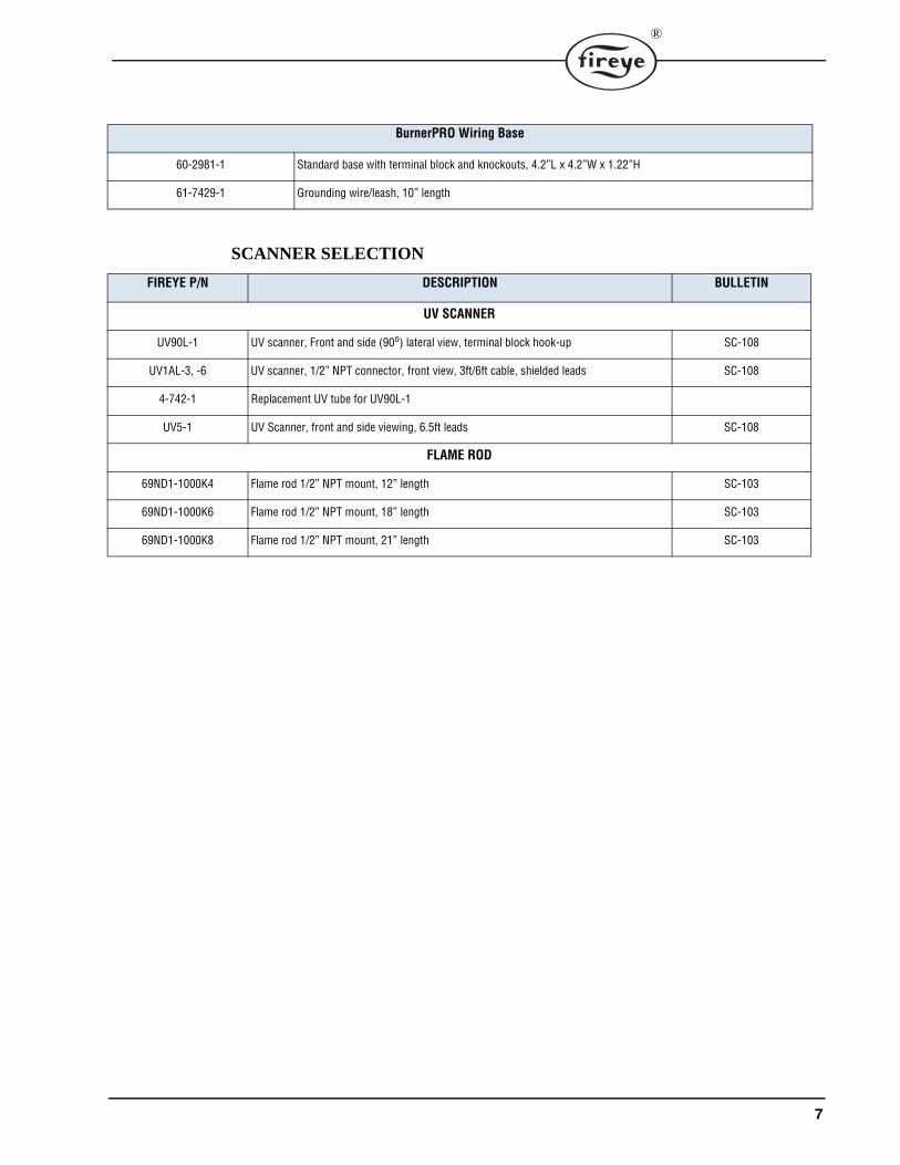
SCANNER SELECTION
BurnerPRO Wiring Base
60-2981-1 Standard base with terminal block and knockouts, 4.2”L x 4.2”W x 1.22”H
61-7429-1 Grounding wire/leash, 10” length
FIREYE P/N DESCRIPTION BULLETIN
UV SCANNER
UV90L-1 UV scanner, Front and side (90o) lateral view, terminal block hook-up SC-108
UV1AL-3, -6 UV scanner, 1/2” NPT connector, front view, 3ft/6ft cable, shielded leads SC-108
4-742-1 Replacement UV tube for UV90L-1
UV5-1 UV Scanner, front and side viewing, 6.5ft leads SC-108
FLAME ROD
69ND1-1000K4 Flame rod 1/2” NPT mount, 12” length SC-103
69ND1-1000K6 Flame rod 1/2” NPT mount, 18” length SC-103
69ND1-1000K8 Flame rod 1/2” NPT mount, 21” length SC-103

8
FIGURE 1.
MOUNTING RECOMMENDATIONS
Wiring Base
Mounting of the base can be accomplished with 2 screws. The recommended screw sizes are #10PAN HD x 5/8inch (5mm PAN HD x 16mm) and #10 PAN HD x 3/8 inch (5mm PAN HD x 10mm).Refer to Figure 2 for mounting dimensions.
Grounding Wire
Each BurnerPRO control is fitted with a grounding wire. Attach the open end of the grounding wireto a ground terminal on the wiring base (see figure 2 below). Undo the screw terminal with a screw-driver and place the ground lug over the terminal. Re-install the screw over the ground lug. Do notattach the grounding wire to a Neutral (N) terminal.
FRONT VIEW BOTTOM VIEW
CHASSIS/AMPLIFIER
110 VAC, 50/60 HzBP110UVFR-Sxxx
230 VAC, 50/60 HzBP230UVFR-Sxxx
WIRING BASE60-2981-1
UV1AL
UV90L

9
®
FIGURE 2.
Note: The location should be free from excessive vibration and within the ambient temperature rating.
NOTICE: Installation, setup, and commissioning of the BurnerPRO control must be done by 's and don’ts of thetrained personnel. The personnel must know the doauthorized and
particular burner and must have relevant experience in the theories and practices of combustion control. Fireye cannot accept any liability for any consequences resulting from inappropriate, negligent or incorrect installation, commissioning or adjustment of operating parameters of theequipment. BurnerPRO does not have any user serviceable parts. If the unit has a problem, return the unit to your local distributor, or contact Fireye directly.

10
TABLE 4: TERMINAL WIRING
Terminal No. Type Description Rating
1 Power Line voltage supply 110VAC (+20%, -15%), 50/60Hz230VAC (+10%, -15%), 50/60Hz
single phase2 Power Line voltage common
3 Output Alarm See Load Ratings
4 Output Lockout Limits 110/230 VAC, 1mA
5 Input Recycle Limits 110/230 VAC, 1mA
6 Output Combustion Air BlowerSee Load Ratings
7 Output Combustion Air Blower
8 Input Actuator Feedback 110/230 VAC, 1mA
9 Output High Fire Purge (Open) See Load Ratings
10 Output Low Fire Purge (Minimum) See Load Ratings
11 Output Closed (Economy) See Load Ratings
12 Input Valve Proving / Proof of Closure 110/230 VAC, 1mA
13 Input Combustion Air Switch Test 110/230 VAC, 1mA
14 Input Combustion Air Prove 110/230 VAC, 1mA
15 Input Valve Proving / Special function 110/230 VAC, 1mA
16 Output Ignition See Load Ratings
17 Output Pilot See Load Ratings
18 Output Main Fuel Valve 1 (MV1) See Load Ratings
19 Output Main Fuel Valve 2 (MV2) See Load Ratings
20 Output Release to Modulate (AUTO) See Load Ratings
21 Input Remote Reset 110/230 VAC, 1mA
22 Output UV Sensor (S1) 300 VDC, 3mA
23 Input UV Sensor (S2) Sensor Common/return
24 Output FR Sensor (S3) 300 VAC, 1mA
N Power Line Voltage Common
Earth Ground
CAUTION: Published load ratings assume that no contact be required to handle inrush cur-rent more often than once in 15 seconds. The use of control switches, solenoid, relays, etc.which chatter can lead to premature failure. It is important to run through a test operation(with fuel shut off) following the tripping of a circuit breaker, a blown fuse, or any knowninstance of chattering of any external current consuming devices.

11
®
INSTALLATION PROCEDURE
Install the wiring base where the relative humidity never reaches the saturation point. The Burner-PRO is designed to operate in a maximum 90% relative humidity environment. Do not install theBurnerPRO where it can be subjected to vibration in excess of 0.5G continuous maximum vibration.Allow at least one inch clearance (2.5 cm) around control for service and installation.
1. Wiring must comply with all applicable codes, ordinances and regulations.2. Wiring must comply with NEC Class 1 (Line Voltage) wiring or equivalent regional code.3. Torque rating on terminal block screws is 4.4 in/lbs to 5.3 in/lbs.4. Limits and interlocks must be rated to simultaneously carry and break current to the ignition
transformer, pilot valve and main fuel valve(s).5. Recommended wire routing of lead wires:
a. Do not run high voltage ignition transformer wires in the same conduit with any otherwires.
b. Do not route flame detector lead wires in conduit with line voltage circuits. Use separateconduit where necessary.
6. Maximum wire lengths:
a.The maximum lead wire length is 200ft. (61 meters) to terminal inputs (Operating limits,interlocks, valves, etc.).
b. Flame Detector lead wires: see section on flame scanners
c. Remote reset: The maximum length of wire is 500 feet (152 meters) to a normally openremote reset push-button, but should remain within sight and sound of the burner.
A good grounding system should be provided to minimize the effects of AC quality problems. Aproperly designed ground system meeting all the safety requirements will ensure that any AC voltagequality problems, such as spikes, surges and impulses have a low impedance path to ground. A lowimpedance path to ground is required to ensure that large currents involved with any surge voltageswill follow the desired path in preferences to alternative paths, where extensive damage may occur toequipment.
BEFORE INSTALLING THE BURNERPRO CONTROL
WARNING: Controls require safety limits utilizing isolated mechanical contacts. Electroniclimit switches may cause erratic operation and should be avoided.
CAUTION: Ensure that electric power is turned off. Refer to SN-100 for recommendedgrounding techniques. Ensure that wiring base terminal is connected to protective earth.
Be aware that power to some interlocks (operating controls, air flow switches, modulatingcircuits, etc.) may be derived from sources other than what is controlling the BurnerPRO.
12
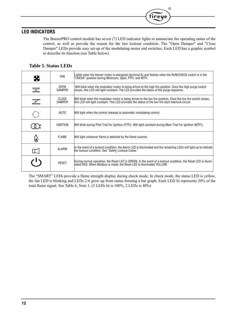
LED INDICATORSThe BurnerPRO control module has seven (7) LED indicator lights to annunciate the operating status of thecontrol, as well as provide the reason for the last lockout condition. The "Open Damper" and "CloseDamper" LEDs provide easy set-up of the modulating motor end switches. Each LED has a graphic symbolto describe its function (see Table below).
Table 5: Status LEDs
The “SMART” LEDs provide a flame strength display during check mode. In check mode, the status LED is yellow,the fan LED is blinking and LEDs 2-6 grow up from status forming a bar graph. Each LED lit represents 20% of thetotal flame signal. See Table 6, Note 1. (5 LEDs lit is 100%, 2 LEDs is 40%)
FAN Lights when the blower motor is energized (terminal 6) and flashes when the RUN/CHECK switch is in the “CHECK” position during Minimum, Open, PTFI, and MTFI.
OPENDAMPER
Will blink when the modulator motor is being driven to the high fire position. Once the high purge switch closes, this LED will light constant. The LED provides the status of the purge sequence.
CLOSEDAMPER
Will blink when the modulator motor is being driven to the low fire position. Once the low fire switch closes, this LED will light constant. This LED provides the status of the low fire start interlock circuit.
AUTO Will light when the control releases to automatic modulating control.
IGNITION Will blink during Pilot Trial For Ignition (PTFI). Will light constant during Main Trial For Ignition (MTFI).
FLAME Will light whenever flame is detected by the flame scanner.
ALARM In the event of a lockout condition, the Alarm LED is illuminated and the remaining LEDs will light up to indicate the lockout condition. See “Safety Lockout Codes.”
RESET During normal operation, the Reset LED is GREEN. In the event of a lockout condition, the Reset LED is illumi-nated RED. When Modbus is made, the Reset LED is illuminated YELLOW.

13
®
Table 6: LED Run-time Status Indicator
NOTES:1.The LEDs form a progress bar indicating Flame Signal Strength for aiming sensors during commissioning (The LEDs “Grow”
upwards away from Status at 20% intervals of flame strength.)2.The LEDs indicate the error or lockout code for troubleshooting3.The LEDs change from ON to BLINKING to OFF showing the modulator operation
OPERATIONLED ● = ON
FANOPEN
DAMPERCLOSED DAMPER
AUTO IGNITION FLAME STATUS
ICON
OFF / NO POWER
OFF
NOT READY / DIAGNOSTICS
Green
READY / STANDBY
● Green
CHANGING(note 3)
●OFF
Blinking●
●Blinking
OFFGreen
WAITING TO CLOSE
Blinking Green
Green
OPEN(before ignition)
● ● Green
MINIMUM(before ignition)
● ● Green
IGNITION ● ● ● Green
PTFI ● ● ●Blinking Green
Green
MTFI ● ● ● Green
AUTO ● ● ● Green
MINIMUM(During Flame)
● ● ● Green
OPEN(During Flame)
● ● ● Green
ECONOMY ● ● Green
CHECKOPEN
Blinking ● Yellow
CHECKMINIMUM
Blinking ● Yellow
CHECKPTFI/MTFI/AUTO
Blinking ● Note 1 ● Note 1 ● Note 1 ● Note 1 ● Note 1 Yellow
FAULT / LOCKOUT
● Note 2 ● Note 2 ● Note 2 ● Note 2 ● Note 2 ● Note 2 Red
END OF CYCLE ● ● ● ● Green

14
FLAME SCANNERS
INSTALLATION - UV SCANNERS
Where possible, obtain the burner manufacturer’s instructions for mounting the scanner. This infor-mation is available for most standard burners. The scanner mounting should comply with the follow-ing general instructions:
1. Position the UV1AL, UV90L or UV5 scanner within 39 inches (1 meter) of the flame to bemonitored.
2. Select a scanner location that remains within the ambient temperature limits of the UV scanner. 3. The UVlAL scanner is designed to seal off the sight pipe up to 1 PSI pressure. Higher furnace
pressures must be sealed off. To seal off positive furnace pressure up to 50 PSI for the UV1ALscanner, install a quartz window coupling (P/N: 60-1257). Add cooling air to reduce the scannersight pipe temperature.
4. Install the scanner on a standard NPT pipe (UV1AL: 1/2”) whose position is rigidly fixed. If thescanner mounting pipe sights through the refractory, do not extend it more than halfwaythrough. Swivel flanges are available if desired (P/N: 60-302). The sight pipe must permit anunobstructed view of the pilot and/or main flame, and both pilot and main flames must com-pletely cover the scanner field of view.
5. Smoke or unburned combustion gases absorb ultra-violet energy. On installations with negativepressure combustion chambers, a small hole drilled in the UV1AL sight pipe assists in keepingthe pipe clean and free from smoke. For positive pressure furnaces, provide clean air to pressur-ize the sight pipe, if necessary.
6. Two UV1AL scanners may be installed on the burner if it is necessary to view two areas toobtain reliable detection of the flame. They must be wired in parallel.
7. To increase scanner sensitivity with UV1AL scanner, a quartz lens permits location of the scan-ner at twice the normal distance. Use 1/2” x 1 1/2” pipe nipple between UV1AL scanner and thecoupling.
8. Request the assistance of any Fireye field office for recommendations of a proper scanner instal-lation on a non-standard application.
UV90LUV1AL
SCANNER MUST HAVE UNOBSTRUCTEDVIEW OF FLAME
NOT THIS NOT THIS BUT THIS
FLAME MUST COMPLETELY COVERSIGHT OPENING
NOT THIS NOT THIS BUT THIS

15
®
TYPICAL SCANNER INSTALLATIONS
WIRING - UV SCANNERS
To connect the scanner to the control, the UV1AL scanner is supplied with 36" or 72" (0.9 m or 1.8 m) of flexible cable. The UV90L is supplied with a terminal board. Use two #18 AWGconductors to connect the UV90L to the control. The UV5 is supplied with 80” (2m) of flexible cable(detachable).
If it is necessary to extend the scanner wiring, the following instructions apply:
There is no polarity associated with the scanner wiring. Scanner wires must be installed in a separateconduit. The wires from several scanners may be installed in a common conduit.
1. Selection of Wire
a. Wiring: For extended scanner wiring up to 500 feet (152 M), and for shorter lengths to reducesignal loss, use a shielded wire (Belden 8254-RG62 coaxial cable, or equal) for each scannerwire. The ends of the shielding must be taped and not grounded.
b. Avoid asbestos insulated wire.
c. Multi-conductor cable is not recommended without prior factory approval.
2. High voltage ignition wiring must not be installed in the same conduit with flame detector wires.
The maximum UV signal from a flame is found in the first one-third of the visible flame taken from the point where the flame begins. The scanner sight pipe is aimed at this area.
DO NOT EXTENDMORE THANHALF-WAY INTOREFRACTORY
SCANNER
FORCEDCLEAN AIR(FROM DISCHARGEOF FAN)
METHODS OF COOLING SCANNER
INSULATINGTUBING
SEALING UNIONFORCED
AIR
EXTEND SIGHTING TUBE6”(152.4) OR 8”(203.2)
DO NOT EXTEND MORE THANHALF-WAY INTO REFRACTORY

16
INSTALLATION - 69ND1 FLAME ROD
The 69NDl flame rod proves a gas pilot flame and/or main gas flame. It is a spark plug type unit. Itconsists of 1/2' “NPT” mount, a KANTHAL flame rod, a glazed porcelain insulating rod holder and
a spark plug connector for making electrical connections. The 69ND1 is available in 12", 18" or 24"(0.3m, 0.46m, 0.6m) lengths.
The flame rod may be located to monitor only the gas pilot flame or both the gas pilot and main gasflames. Mount it with a l/2" “NPT” coupling.
The following instructions should be observed:
1. Keep your flame rod as short as possible.
2. Keep your flame rod at least 1/2" from any refractory. 3. Your flame rod must enter the pilot flame from the side so as to safely prove an adequate pilot
flame under all draft conditions.4. If the flame is nonluminous (air and gas mixed before burning), extend the electrode tip at least
1/2" into the flame, but not more than halfway through.
5. If the flame is partly luminous, the electrode tip must extend only to the edge of the flame. It isnot necessary to maintain uninterrupted contact with the flame.
6. It is preferable to angle the rod downward to minimize the effect of sagging and to prevent itfrom coming in contact with any object.
7. An adequate grounding surface for the flame must be provided. The grounding surface in actualcontact with the flame must be at least 4 times greater that the area of the portion of the flamerod in contact with the flame. It is essential to adjust the flame rod and ground area ratio to pro-vide a maximum, signal reading.
Note: Interference from the ignition spark can alter the true signal reading by adding to, or subtract-ing from it. This trend sometimes may be reversed by interchanging the primary wires (line voltage)to the ignition transformer. This interference can also be reduced by the addition of grounded shield-ing between the flame rod and ignition spark.
8. Proven types of flame grounding adapters, as shown below, may be used to provide adequategrounding surface. High temperature stainless steel should be used to minimized the effect ofmetal oxidation. This assembly may be welded directly over the pilot or main burner nozzle.
WRONG POSITIONOF ROD
INADEQUATE FLAME
PILOT BURNER
CORRECT POSITIONOF PILOT FLAME
CORRECTPOSITIONOF ROD
BOMB FIN GROUNDING ASSEMBLY THREADED ROD ASSEMBLY

17
®
WIRING - FLAME RODFor proper operation of flame rectification systems, it is necessary to maintain at least 20 megohms insulat-ing resistance in the flame rectification circuit.
1. The scanner should be wired using metal cable or rigid conduit.
2. High voltage wiring must not be installed in the same conduit with scanner wiring.
Selection of Scanner Wire
1. Use #14, 16, or 18 gauge wire with 90 C, 600 volt insulation for up to 20 feet distance.
2. The type of insulation used with flame rectification is important, since it must protect against currentleakage resistance to ground. Use Belden 8254-RG62 Coaxial Cable (or equal) for runs greater than 20feet. Maximum wiring run not to exceed 100 feet.
MAINTENANCE - FLAME ROD
Type 69ND1 Flame Rod
The flame rod and its insulator should be kept clean by washing routinely with soap and water. Rods shouldbe routinely replaced as they oxidize.
Flame Signal Strength
Routine observation of the flame signal strength will forewarn any deterioration in the capability of theflame detector or its application.

18
SYSTEM OPERATIONThe fixed series timings determine the functional operation of the BurnerPRO control (e.g. purge tim-ing, trial for ignition timings, etc.) The BurnerPRO offers a single multi-functional button and its func-tions are as follows:
RESET
The BurnerPRO control provides two methods of resetting the control in the event of a safety lockout:The push button reset and terminal 21 remote reset. Both reset methods can be used to stop the controlin its firing sequence at anytime to force a user/emergency lockout. A reset of the control can beaccomplished by momentarily pressing the reset button or engaging the remote reset terminal.
CHECK MODE
The push button reset switch has an added feature that allows the user to freeze the operationalsequence at certain times (Purge, Ignition, PTFI, MTFI, and AUTO). This is known as CHECKMODE and it is designed to aid in set-up, start-up and check-out of the burner and its associated inter-locks. This feature is very useful in pilot aiming and adjustment during commissioning or mainte-nance.
The check mode rules are:
• If the push button reset is held for at least 3 seconds, the status LED changes from green to yellowto signal that the control is in check mode.
• Momentarily pressing the push button reset while in check mode transitions the control into nor-mal operating sequence, thus disabling check mode.
• The control locks out during Purge, Ignition, or PTFI states if check mode is active longer than 30minutes
• The control allows check mode in MTFI for 2 minutes. The control automatically cancels checkmode after 2 minutes in MTFI state and resumes normal operation.
• When in check mode during PTFI, MTFI and AUTO states, the control uses the open, close, auto,ignition, and flame LEDs to annunciate the flame signal strength. Every illuminated LED (startingwith the flame LED) represents a 20% signal strength.
• It should be noted that the control will still perform safety checks in the background while inCHECK mode to ensure the safe operation of the burner. The control will proceed to lockout if itdetects an unsafe condition.
19
®
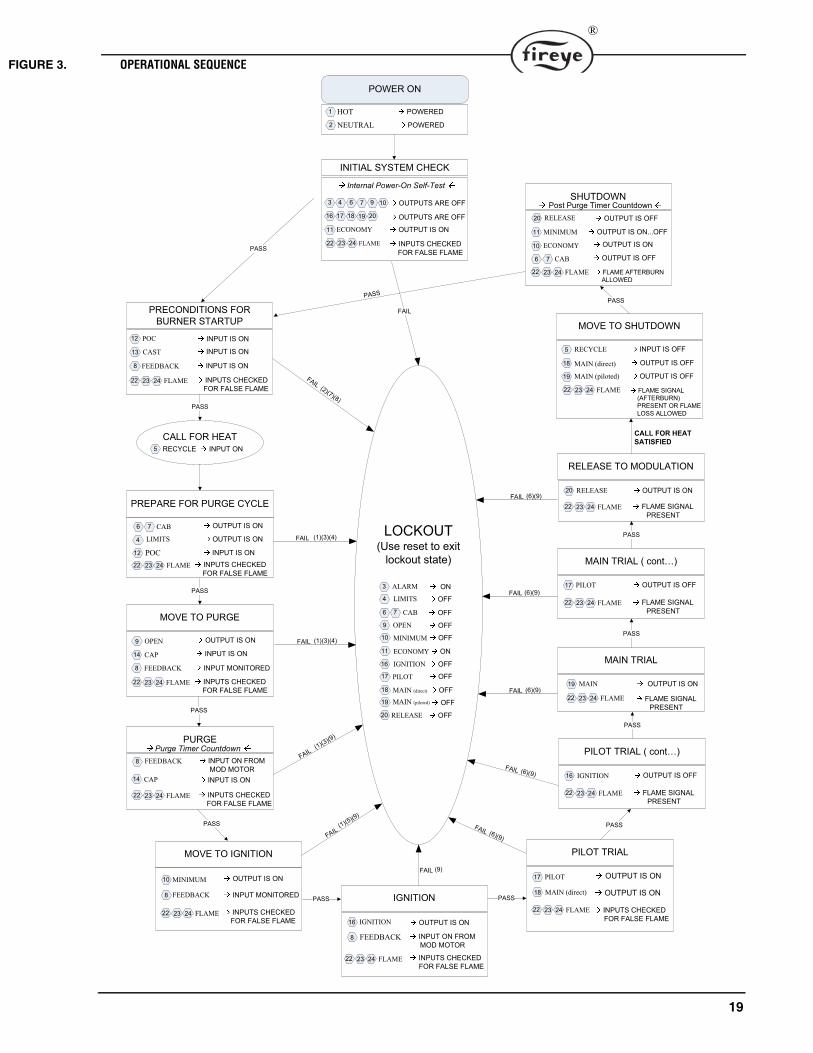
FIGURE 3. OPERATIONAL SEQUENCE
�������������� ��
���������������
���������������
��������������
��������� ���������������������
������������������������������
�������������
������������
������������
�������
���
��
��� ���
����������������������������� �!����"��#
��������� ����������� ���������
�������������$�����
��������������
������������
�������������
��
�����
���
��%�������$
��������������
������������
����
��
������������������ ���
���$�������������� ���� �
��������������
������������������������
��� ���
��������� ���������������������
��%�����$������
�$������
���������������������
������������������� ���
��������������������
����������������������������
��� ���
������������
������������������
������������ �������������
����������������&�'#
�������� ��������������
����������
�����������������
������������������
����� �������������
��%����� ����(�
������� �������������
������������ ��������������
�������� ���� ��������������
� ����(�
������� �������������
����� ��������������
������� �������������)))���
��� ��������������
�������!�*����+�����!&�,�-&�
��(����
.
/
0 1 2 3 4 .5
.2 .3 .6 .4 /5
..
// /0 /1
���(��!��
���(���������
./
.0
6
7
����
����
����
����
2
1
./
4
.1
6
.1
6
// /0 /1
����
����
����
.5
6
��������� ��������������������
// /0 /1 ����
����
.2
6
��������� ����������������������
// /0 /1 ����
����
.3
��������� ���������������������
// /0 /1 ����
.6
����
.2
��������$��������
// /0 /1 ����
.4
��������$��������
// /0 /1 ����
/5
��������$��������
// /0 /1 ����
����
����
7
.6
.4
/5
��������$����������������������#��������������������������������������������(�
// /0 /1 ����
�������������� �� �
..
.5
2����
��������� ��������������������
// /0 /1 ���� ����� �/#�3#�6#
3
����� �.#�0#�1#
�.#�0#�4
#
�����
�.#�7#�4
#
�����
������4#
���������������&�'#
����� ��������������.3
��������$��������
// /0 /1 ����
����
����
����� �2#�4#
����� �2#�4#
����� �2#�4#
������2#�4#
����� �2#�4#
0 �������
1 ���������
2 ������
4 ��������
.5 �����������
.. ����������
3
.2 ������������
.3 ���������
.6 ����������������
.4 ������������ ����
/5 ���������
3
�� ��� ���������� �����������
���������������������������(�
// /0 /1 ����
��������� ���������������������
// /0 /1 ����
����
����
�.#�0#�1#
��������� ���������������������
����// /0 /1

20
NOTES:1)Presence of flame at this point results in a lockout.2)When CAST (terminal 13) is open and POC (terminal 12) is open at this point, control locks out after 10 minutes. When
CAST is open and POC is closed, control remains in same state indefinitely.3)Control locks out if FEEDBACK (terminal 8) is not present after 10 minutes.4)CAP (terminal 14) input is required to proceed. Otherwise, control locks out, after 10 minutes.5)FEEDBACK (terminal 8) must remain present. Otherwise, control locks out, after 10 minutes.6)Presence of real flame is mandatory. Otherwise, control locks out. Flame failure results in Post-Purge at lockout.7)The control locks out if POC (FVES) cannot be proven closed upon call for heat.8)Presense of flame for more than 60sec at this point will result in a lockout.9)CAP (Terminal 14) input must remain present. Otherwise, control will lockout.
EXPLANATION OF SEQUENCE STATES
1) POWER ON
This is the application of power to the control. It's important that a single phase (110/230 VAC 50/60 Hz) isapplied to the control and the inputs to the control are sourced from the same phase.
2) INITIAL SYSTEM CHECK
During this state, the control undergoes an internal Power-On Self-Test (POST) to verify that the hardwareand software are operating properly. The non-volatile lockout feature forces the control to move to lockoutif the last lockout condition was not cleared prior to power off. The control further checks the critical inputand output terminals to make sure they are in the proper state. The control expects the flame to be com-pletely extinguished at this point.
3) PRECONDITIONS FOR BURNER STARTUP
The control verifies that the air-flow switch is in the Normally Closed position via the Combustion AirSwitch Test (CAST) input and a verification of the main fuel shutoff valve (POC/FVES) is performed aswell. Flame must not be present at this point. Failure to prove POC or CAST input will lead to a halt in thestate sequence or the control will proceed to lockout.
4) CALL FOR HEAT
The recycle limit (terminal 5) is energized to alert the control to start a burner cycle.
5) PREPARE FOR PURGE CYCLE
The control turns on the combustion blower (terminals 6 & 7).
6) MOVE TO PURGE
The control commands the damper actuator to move to the OPEN (high fire) position. It expects the actua-tor to report a successful transition to the OPEN position by energizing the FEEDBACK input (terminal 8).The control also checks to make sure that the airflow switch is operating by monitoring the CAP input.
7) PURGE
The control purges the combustion vessel for a period of time (length of purge is based on the control seriesinstalled).
8) MOVE TO IGNITION
Upon successful purging, the control moves to ignition by energizing the MINIMUM output (terminal 10).It expects the actuator to report a successful transition to the MINIMUM (LOW FIRE) position by energiz-ing the FEEDBACK input (terminal 8). Flame must not be present at this point.
9) IGNITION
The control energizes the ignition transformer by activating terminal 16. It's critical that the damper actua-tor remain at the MINIMUM (LOW FIRE) position during this state. Flame must not be present at thispoint.

21
®
10) PILOT TRIAL (1st safety time)
The control turns on the pilot flame by energizing terminal 17. The MAIN direct output (terminal18) is also energized for systems that implement direct light-off of the main flame during pilot.The control doesn't check for flame during this phase as the flame may not be fully established.
11) PILOT TRIAL (1st safety time)
The ignition transformer is turned off. The pilot flame signal is proven during this phase. Failureto “see” a flame results in a lockout.
12) MAIN TRIAL (2nd safety time)
The main fuel valve (piloted) output (terminal 19) is energized to light-off the main flame. Flamesignal must be present during this phase.
13) MAIN TRIAL (2nd safety time)
The pilot output (terminal 17) is turned off during this phase. Flame signal must remain present.
14) RELEASE TO MODULATION
After successfully establishing flame, the control proceeds to relinquish modulation control to theboiler management system. Flame signal must remain present. Terminal 20 is energized.
15) MOVE TO SHUTDOWN
Move to shutdown occurs when the load demand has been satisfied and the RECYCLE LIMIT(terminal 5) is open. This forces the control to close the main fuel valves by de-energizing MAINDIRECT (terminal 18) and MAIN PILOTED (terminal 19) outputs. The combustion air blowerremains on for post-purge. Flame afterburn is allowed during this phase
16) SHUTDOWN
The control proceeds to purge the combustion chamber for a period of time (length of post-purgeis based on the control series installed). Then it proceeds to the MINIMUM (low-fire) positionand later to the ECONOMY (closed) position. After successfully completing a post-purge cycle,the control turns off the combustion air blower. Any flame afterburn is expected to be completedat the completion of post-purge.
17) LOCKOUT
The control proceeds to a lockout state when it detects an internal or external fault condition. Thereset button and remote reset terminal can be used to exit the lockout state. However, the controlwill revert to lockout if the fault condition is not rectified.
18) VALVE PROVING (not shown in drawing)
If the control supports valve proving, it will perform valve proving operation at pre-purge or post-purge -- depending on the parameter selection by the installer. By default, valve proving is pro-grammed to occur during pre-purge. A failure of the valve proving operation will force the controlto proceed to lockout. Upon a successful completion of valve proving operation, the control willproceed to the next state -- if valve proving is configured for pre-purge, the control will move topurge state upon completion of valve proving; if valve proving is configured for post-purge, thecontrol will move to standby state upon successful completion of valve proving.

22
FIGURE 4.

23
®
Table 3:
NOTE: unless stated as minimum or maximum, timings are nominal values.
a: Minimum time
b: Maximum time
Table 7: EXPANDED TIMINGS TABLE
Times are in seconds BURNERPRO SERIES TIMINGS
TIMING DESCRIPTION S1 S2 S3 S4 S5 S6
t1 Purge time 36 31 37 60 37 30
t3 Pre-ignition time (direct fired) 4 6 5 5 5 10
t3' Pre-ignition time (piloted) 4 6 2.5 2.5 2.5 1
TSA Ignition safety time (direct ignition) 2 3 2.5 2.5 2.5 1
TSA’ Ignition safety time (PTFI) 2 3 5 5 5 10
t4 Interval between voltage on Pilot/Main Fuel Direct and Main Fuel Piloted 10 11.5 12.5 12.5 12.5 5
t4' Internal between start of TSA and the main fuel piloted 10 11.5 15 15 15 15
t5 Interval between Main Fuel Piloted and release to Modulation 10 11.5 12.5 12.5 12.5 15
t6 Post-purge time 12 18 15 15 15 15
t7 Pilot stabilization period 8 8.5 10 10 10 5
t9 Interval between Main Fuel Piloted and removal of Pilot (MTFI) 2 3 5 5 5 10
t11 Air damper running time to the HIGH FIRE position OPTIONAL
t12 Air damper running time to the LOW FIRE position OPTIONAL
t13 Permissible afterburn time (Post-purge + 60s) 72 78 75 75 75 75
FFRT Flame Failure Response Time (FFRT) 1.0b 4.0b
24
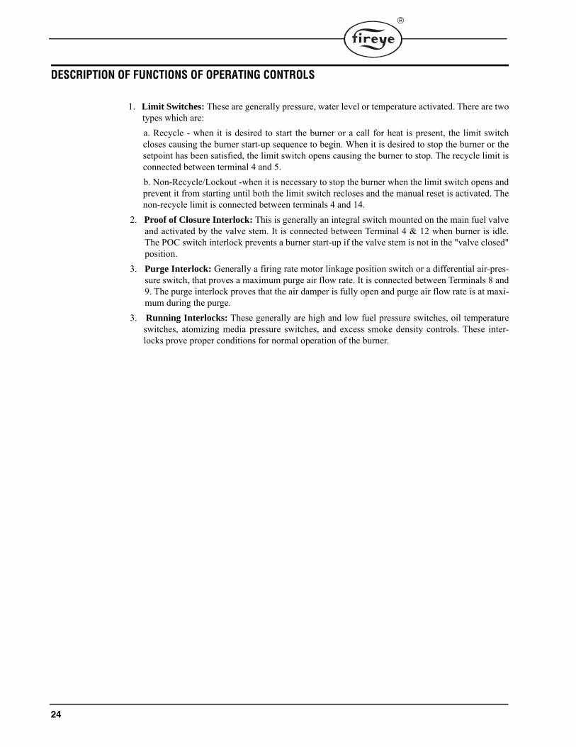
DESCRIPTION OF FUNCTIONS OF OPERATING CONTROLS
1. Limit Switches: These are generally pressure, water level or temperature activated. There are twotypes which are:
a. Recycle - when it is desired to start the burner or a call for heat is present, the limit switchcloses causing the burner start-up sequence to begin. When it is desired to stop the burner or thesetpoint has been satisfied, the limit switch opens causing the burner to stop. The recycle limit isconnected between terminal 4 and 5.
b. Non-Recycle/Lockout -when it is necessary to stop the burner when the limit switch opens andprevent it from starting until both the limit switch recloses and the manual reset is activated. Thenon-recycle limit is connected between terminals 4 and 14.
2. Proof of Closure Interlock: This is generally an integral switch mounted on the main fuel valveand activated by the valve stem. It is connected between Terminal 4 & 12 when burner is idle.The POC switch interlock prevents a burner start-up if the valve stem is not in the "valve closed"position.
3. Purge Interlock: Generally a firing rate motor linkage position switch or a differential air-pres-sure switch, that proves a maximum purge air flow rate. It is connected between Terminals 8 and9. The purge interlock proves that the air damper is fully open and purge air flow rate is at maxi-mum during the purge.
3. Running Interlocks: These generally are high and low fuel pressure switches, oil temperatureswitches, atomizing media pressure switches, and excess smoke density controls. These inter-locks prove proper conditions for normal operation of the burner.

®
CONNECTION TO AN EXTERNAL ACTUATOR
BurnerPRO is designed to interface with an external actuator. It offers direct interfacing to common actuatorsthat support line voltage signaling (see figure below). It can also be wired with low voltage actuators with theaid of interposing relays (see figure below)
11Economy(Closed)
10Mininimum(Low Fire)
9Open
(High Fire)
NON-DIRECT INTERFACING
L2
RA RB
R
R
KB1
KB2
B
W
POTENTIOMETERCONTROLLER
W
TT
FIRING RATEMOTOR
Power Supply
KA1
8Feedback
B
KA2KA/KB = SPDT
20Release(Auto)
Low FireSwitch
Purge AirFlow Switch
8Feedback
11Economy(Closed)
10Minimum(Low Fire)
20Release(Auto)
LOW REL
Line Level Inputs
LOAD CONTROLDIRECT INTERFACING
9Open
(High Fire)
AUX(closed)POS HIGH

26
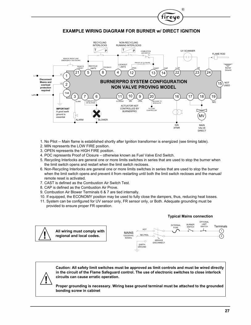
27
®

28

29
®
C0MMUNICATIONS
The protocol to be used is Modbus RTU. This is implemented by the master (PC, PLC, etc.) issuinga poll to the slave (BurnerPRO) and the slave responding with the appropriate message.
A typical format of a poll request is as follows:
Table 1: MESSAGE FORMAT
DST refers to the logical address of the slave.
FNC is the function being requested. FNC 03 is a read request.
ADR is the message number or register number of the data being requested.
For the BurnerPRO all registers are mapped as HOLDING REGISTERS, FNC 03. Registeraddresses begin at 40001 but is interpreted as address 00.
DAT is the number of words being requested. A word is an integer consisting of 2 bytes.
The normal response from a slave is as follows:
Table 2: MODBUS
DBC is the data byte count being returned. It must be two times the DAT number from the pollrequest.
DATA is the data returned and is always a series of 2 byte integers. If 4 words were requested thenDBC would be 8 and there would be 8 data bytes or 4 data words containing the requested data.
The default format of the data is N,8,1 meaning no parity, and 1 stop bit. Baud rate is select-able through the keypad / display. As shipped the baud rate is 9600.
Communication to the BurnerPRO control is made through the RJ45 port located on the side of thecontrol. Since the RJ45 port is not compliant with a standard network Ethernet pinout, it’s highlyrecommended that an ED610 breakout board be utilized to gain physical access to the modbus com-munication signals. The physical method for communications is RS485, half duplex. The modbuscommunication signals are designated “A” or “-”and “B” or “+”. Fireye offers a Modbus connectionkit for the BurnerPRO. The kit consists of the ED610 breakout board, 6ft CAT5 Ethernet cable, anda wall mount power supply. Fireye also offers the UC485 USB adapter for connection to a PC.
DST FNC ADR
HI
ADR
LO
DAT
HI
DAT
LO
CRC
LO
CRC
HI
DST FNC DBC DATA….
Hi/Lo
CRC
LO
CRC
HI

30

31
®
32
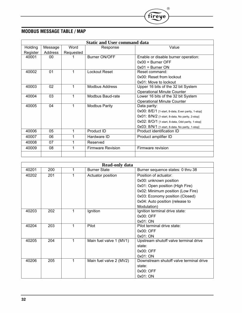
MODBUS MESSAGE TABLE / MAP
Static and User command dataHolding Register
Message Address
Word Requested
Response Value
40001 00 1 Burner ON/OFF Enable or disable burner operation:0x00 = Burner OFF0x01 = Burner ON
40002 01 1 Lockout Reset Reset command:0x00: Reset from lockout0x01: Move to lockout
40003 02 1 Modbus Address Upper 16 bits of the 32 bit System Operational Minute Counter
40004 03 1 Modbus Baud-rate Lower 16 bits of the 32 bit System Operational Minute Counter
40005 04 1 Modbus Parity Data parity:0x00: 8/E/1 [1-start, 8-data, Even parity, 1-stop]
0x01: 8/N/2 [1-start, 8-data, No parity, 2-stop]
0x02: 8/O/1 [1-start, 8-data, Odd parity, 1-stop]
0x03: 8/N/1 [1-start, 8-data, No parity, 1-stop]
40006 05 1 Product ID Product identification ID
40007 06 1 Hardware ID Product amplifier ID
40008 07 1 Reserved
40009 08 1 Firmware Revision Firmware revision
Read-only data40201 200 1 Burner State Burner sequence states: 0 thru 38
40202 201 1 Actuator position Position of actuator:0x00: unknown position0x01: Open position (High Fire)0x02: Minimum position (Low Fire)0x03: Economy position (Closed)0x04: Auto position (release to Modulation)
40203 202 1 Ignition Ignition terminal drive state:0x00: OFF0x01: ON
40204 203 1 Pilot Pilot terminal drive state:0x00: OFF0x01: ON
40205 204 1 Main fuel valve 1 (MV1) Upstream shutoff valve terminal drive state:0x00: OFF0x01: ON
40206 205 1 Main fuel valve 2 (MV2) Downstream shutoff valve terminal drive state:0x00: OFF0x01: ON

33
®
40207 206 1 AUTO Release to modulation drive state:0x00: OFF0x01: ON
40208 207 1 Recycle Limit Recycle limit terminal state:0x00: OFF0x01: ON
40209 208 1 POC Proof of closure terminal state:0x00: OFF0x01: ON
40210 209 1 CAST Combustion air switch test terminal state:0x00: OFF0x01: ON
40211 210 1 CAP Combustion air prove terminal state:0x00: OFF0x01: ON
40212 211 1 Actuator feedback Actuator feedback terminal state:0x00: OFF0x01: ON
40213 212 1 Valve Proving States Valve proving test states:0x00: Test not started0x01: Test started0x02: Evacuate test space0x03: Test Time 1 phase0x04: Test time 1 complete0x05: Pressurize test space0x06: Test time 2 phase0x07: Test time 2 complete0x08: Valve proving complete0x09: Valve proving complete
40214 213 1 Valve prove test counter Countdown timer for valve proving in sec
40215 214 1 Actuator feedback counter
Actuator feedback waiting timer
40216 215 1 CAST timer Combustion air switch test waiting timer
40217 216 1 CAP timer Combustion air prove waiting timer
40218 217 1 POC counter Proof of closure waiting timer
40219 218 1 Pre-purge counter Pre-purge countdown timer
40220 219 1 Post-purge counter Post-purge countdown timer
40221 220 1 Check mode timer Check mode timer
40222 221 1 Remote Reset attempts Shows the number of remote reset applied by the user in the alloted window [15mins]
40223 222 1 Reset inhibit timer Countdown timer to restore remote reset operation
40224 223 1 Burner minutes Burner ON minutes
40225 224 1 Burner seconds Burner ON seconds
40226 225 1 System minutes System ON minutes
40227 226 1 System seconds System ON seconds
40228 227 1 Operating frequency (MCU 1)
Line voltage frequency:0x00: 50Hz 0x00: 60hz

34
40229 228 1 Operating frequency (MCU 2)
Line voltage frequency:0x00: 50Hz 0x00: 60hz
40230 229 1 Terminal 15 (VPS) Status of terminal 150x00: Inactive0x01: Active
40231 230 1 Burner cycle count Number of burner cycles completed
40232 231 1 Cycle hold timer countdown to show the expiration of inter-cycle delay
40233 232 1 Flame permissible timer Countdown to show allowable flame afterburn
40234 233 1 Flame sensor Flame sensor input identified during the burner sequence:0x01: UV0x02: FR
40235 234 1 Flame strength Flame strength based raw sensor input
40236 238 1 Reset source Reset source:0x00: No reset0x01: Local reset (button)0x02: Remote terminal reset0x03: Modbus reset
40240 239 1 Lockout count Total system lockout count
40241 240 4 Lockout history 1 (most recent)
BurnerPRO stores the last 10 lockout information. Each lockout history is stored using 4 words: 1st word: Lockout reason code2nd word: Burner state at time of lockout3rd word: Burner minutes4th word: Burner cycles
40245 244 4 Lockout history 2
40249 248 4 Lockout history 3
40253 252 4 Lockout history 4
40257 256 4 Lockout history 5
40261 260 4 Lockout history 6
40265 264 4 Lockout history 7
40269 268 4 Lockout history 8
40273 272 4 Lockout history 9
40277 276 4 Lockout history 10

35
®
VALVE PROVINGThe BurnerPRO offers an intelligent Valve Proving System (VPS). It checks the effective closure of auto-matic shut-off valves by measuring the pressure differential between two fuel shutoff valves during the testsequence. When active, it will open and close the main safety shutoff valves (double block valve arrange-ment) in the proper sequence and monitor the pressure in the gas pipe between the two safety shutoff valves(MV1 & MV2).
The gas pressure sensing device, pressure switch, is recommended to be installed between the two shutoffvalves. The two common methods of pressure switch setup are described below:
Method 1: A single pressure switch installed between the shutoff valves.
This setup requires that the gas pressure switch be adjusted to ½ the gas train pressure. The rule of operationis quite simple: The pressure switch will "make" (DI2 high) when gas pressure in the test section exceeds theset pressure; it will "break" (DI1 high) when the gas pressure falls below the set pressure.
Method 2: Dual pressure switches installed between the shutoff valves.
WARNING: It is the responsibility of the installing and operating personnel to ensure that the valve prov-ing system is properly installed and configured. The appropriate permissible leakage rate informationshould be used when setting up a valve proving system. Please consult the burner manufacturer and/orapplicable codes, ordinances, and regulations.
36
This setup requires that the gas pressure switches be adjusted to levels closer to the high and low pressurewindows. Thus, allowing for the detection of trace amount of gas leakage and it also reduces the overall TESTtimes. The rule of operation is similar to the single pressure switch setup: The pressure switch will "make"(T15 high) when gas pressure in the test section exceeds the high side set pressure; it will "break" (T12 high)when the gas pressure falls below the low side set pressure.
Pressure Switch Selection
1. Determine the maximum inlet pressure for the upstream valve.
2. For method 1, divide the inlet pressure by 2 (50%) and select a gas pressure switch that will trip at the half-way point. For adjustable type pressure switches, adjust the setting to the desired trip point.
3. For method 2, determine the trip point for the high and low side pressure. Select pressure switches to satisfythe high and low side pressure settings. For adjustable type pressure switches, adjust the setting to the desiredtrip point.
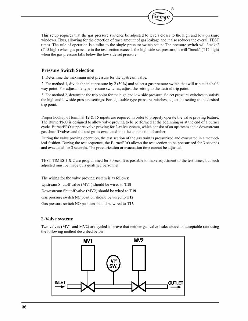
Proper hookup of terminal 12 & 15 inputs are required in order to properly operate the valve proving feature.The BurnerPRO is designed to allow valve proving to be performed at the beginning or at the end of a burnercycle. BurnerPRO supports valve proving for 2-valve system, which consist of an upstream and a downstreamgas shutoff valves and the test gas is evacuated into the combustion chamber.
During the valve proving operation, the test section of the gas train is pressurized and evacuated in a method-ical fashion. During the test sequence, the BurnerPRO allows the test section to be pressurized for 3 secondsand evacuated for 3 seconds. The pressurization or evacuation time cannot be adjusted.
TEST TIMES 1 & 2 are programmed for 30secs. It is possible to make adjustment to the test times, but suchadjusted must be made by a qualified personnel.
The wiring for the valve proving system is as follows:
Upstream Shutoff valve (MV1) should be wired to T18
Downstream Shutoff valve (MV2) should be wired to T19
Gas pressure switch NC position should be wired to T12
Gas pressure switch NO position should be wired to T15
2-Valve system:
Two valves (MV1 and MV2) are cycled to prove that neither gas valve leaks above an acceptable rate usingthe following method described below:

37
®
Proving steps:
1. Both safety shutoff valves are in the closed position at the start of valve proving sequence.
2. The downstream valve (MV2) is energized (open) for 3 seconds. Thus, evacuating the test space.
3. The downstream valve is closed after the evacuation time.
4. The system monitors the pressure switch within the configured TEST TIME 1 window to verify that theupstream valve is not leaking. If the pressure switch is energized (makes) during this window, the systemwill stop the valve proving test and proceed to lockout. Otherwise, the system will proceed to the nextphase of the test.
5. The upstream valve (MV1) is open for 3 seconds. Thus, pressurizing the test space.
6. The upstream valve is closed after the pressurization time.
7. The system monitors the pressure switch within the configured TEST TIME 2 window to verify that thedownstream valve is not leaking. If the pressure switch is de-energized (drops out) during this window, thesystem will stop the valve proving test and proceed to lockout.
8. Upon successful completion of TEST TIME 2, the valve proving test is deemed complete and the Burner-PRO proceeds to start the pre-purge cycle.

38
CALCULATING VALVE PROVING TEST TIMES
The valve proving test times are expected to be calculated by using the following formula:
Where:
Test Time = Duration of proving time (in seconds)
∆P = Difference between inlet pressure and the switch point of pressure switch
(English -- psi, Metric -- mbar)
VP = Volume of test section (English -- ft3, Metric -- dm3)
C = Formula constant (3600 sec/hr)
PATM = Atmospheric pressure (default 14.7 psi or 1013 mbar)
VLEAK = Permissible leak rate for valves (English -- ft3/hr, Metric -- liters/hr)
In many cases, the volume of the test section, VP, between the gas shutoff valves is specified in the gas trainmanual. Alternatively, the volume can be calculated by:
VP = Volume of the test pipe between the valves + volume of the upstream valve outlet cavity + volume of thedownstream outlet cavity.
As specified in EN 1643:2014 standard, a valve proving system must be leak-tight such that:
• No single component of a VPS shall have a leak rate greater than 60 cm3/hr (0.00212 ft3/hr)for non-integrated double block valves.
• No single component of a VPS shall have a leak rate greater than 120 cm3/hr (0.00424 ft3/hr)for integrated or partially integrated double block valves.
As specified in FM 7400 standard, a valve proving system must be leak-tight with a leak rate no greater than24in3/hr (0.0138 ft3/hr, 393 cm3/hr)
In certain cases, local codes may require the factoring of the burner capacity in order to derive the leak rate.For example, it could be specified that the leakage shall not be greater than 0.01% of burner capacity.
Example of Test Times Calculation:
Assume a valve proving installation with an integrated valve train consisting of total volume of 0.018 ft3, andan inlet pressure of 0.5 psi and a permissible leakage rate of 0.04 ft3/hr for upstream valve and 0.035 ft3/hr for
WARNING: It is the responsibility of the installing and operating personnel to ensure that the valve prov-ing system is properly installed and configured. The appropriate permissible leakage rate informationshould be used when setting up a valve proving system. Please consult the burner manufacturer and/orapplicable codes, ordinances, and regulations.

39
®
downstream valve. Assume a single pressure switch is installed and set to trip at 50% of the inlet pressure.Calculate the expected test times for such system.
For the example above, round up TEST TIME 1 to 30 seconds and TEST TIME 2 to 35 seconds.

40
LOCKOUTSWhen a safety shutdown occurs, the control LEDs indicate the reason for the lockout. The alarm cir-cuit (Terminal “3”) is energized. The non-volatile memory remembers the status of the control evenif a power failure occurs. By momentarily depressing and releasing the manual reset button on thecontrol or Terminal 21 remote reset, the control can be reset. The button must be held down for onesecond and then released. Very little force is required to do this. Do not press hard.
RESETTING THE CONTROL
The BurnerPRO system contains 2 methods of reset: Push button reset and remote terminal reset.The remote reset should be a normally open switch connected from line voltage to terminal 21 (seeexample wiring diagrams).
• Reset is required following a non-volatile lockout.
• Depressing the push button reset momentarily causes the system to recover from a lockout.
• Depressing and releasing the reset button during run mode causes the control to go into lockout.
• The BurnerPRO limits the amount of remote reset attempts to 5 tries in a 15 minutes window.
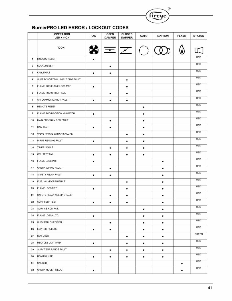
BURNERPRO LED ERROR / LOCKOUT CODESDuring an alarm condition, the status LED turns solid red. The remaining LEDs are illuminated as a coded sequence identifying the reason for the lockout. The following table shows the various LED Lockout codes:
NOTICE: Regulation prohibits the system from allowing more than 5 remote reset attemptsin a 15-minute window. If 5 reset attempts are made without addressing the lockout, the sys-tem will prevent the user from issuing additional remote resets and it will force the user towait for the balance of 15 minutes. Remote reset operation will be restored after the waitperiod. It is expected that a qualified personnel assess the lockout condition and apply theproper remedy to address the lockout.
Boiler operation, maintenance, and troubleshooting shall only be conducted by trained personnel. Persons trouble-shooting lockouts or resetting the control must respond properly to troubleshooting error codes as described in this product bulletin.
Jumpers being used to perform static test on the system must only be used in a controlled manner and must be removed prior to the operation of the control. Such tests may verify the external controllers, limits, interlocks, actua-tors, valves, transformers, motors and other devices are operating properly. Such tests must be conducted with man-ual fuel valves in the closed position only. Replace all limits and interlocks not operating properly, and do not bypass limits in interlocks. Failure to follow these guidelines may result in an unsafe condition hazardous to life and prop-erty.
WARNING!!!
WARNING: The equipment described in this manual is capable of causing property damage, severeinjury, or death. It is the responsibility of the owner or user to ensure that the equipment described isinstalled, operated and commissioned in compliance with the requirements of all national and local codes.
41
®
BurnerPRO LED ERROR / LOCKOUT CODESOPERATIONLED ● = ON
FANOPEN
DAMPERCLOSED DAMPER
AUTO IGNITION FLAME STATUS
ICON
1 MODBUS RESET ●RED
2 LOCAL RESET ●RED
3 CAB_FAULT ● ●RED
4 SUPERVISORY MCU INPUT DIAG FAULT ●RED
5 FLAME ROD FLAME LOSS MTFI ● ●RED
6 FLAME ROD CIRCUIT FAIL ● ●RED
7 SPI COMMUNICATION FAULT ● ● ●RED
8 REMOTE RESET ●RED
9 FLAME ROD DECISION MISMATCH ● ●RED
10 MAIN PROGRAM SEQ FAULT ● ●RED
11 RAM TEST ● ● ●RED
12 VALVE PROVE SWITCH FAILURE ● ●RED
13 INPUT READING FAULT ● ● ●RED
14 TIMER2 FAULT ● ● ●RED
15 CPU TEST FAIL ● ● ● ●RED
16 FLAME LOSS PTFI ● ●RED
17 CHECK WIRING FAULT ● ●RED
18 SAFETY RELAY FAULT ● ● ●RED
19 FUEL VALVE OPEN FAULT ● ●RED
20 FLAME LOSS MTFI ● ● ●RED
21 SAFETY RELAY WELDING FAULT ● ● ●RED
22 SUPV SELF-TEST ● ● ● ●RED
23 SUPV CS ROM FAIL ● ●RED
24 FLAME LOSS AUTO ● ● ●RED
25 SUPV RAM CHECK FAIL ● ● ●RED
26 EEPROM FAILURE ● ● ● ●RED
27 NOT USED ● ● ●GREEN
28 RECYCLE LIMIT OPEN ● ● ● ●RED
29 SUPV TEMP RANGE FAULT ● ● ● ●RED
30 ROM FAILURE ● ● ● ● ●RED
31 UNUSED ●RED
32 CHECK MODE TIMEOUT ● ●RED

42
The table above shows the various required LED error/lockout codes displayed on the BurnerPRO after a fault or errorhas occurred.
33 STANDBY FALSE FLAME ● ●RED
34 T21/EMERGENCY LOCKOUT ● ● ●RED
35 SW WDT RESET ● ●RED
36 SW RESET ● ● ●RED
37 INPUTS WAITING TIME FAULT ● ● ●RED
38 VALVE PROVE TEST TIME 1 FAIL ● ● ● ●RED
39 VALVE PROVE TEST TIME 2 FAIL ● ●RED
40 HARDWARE RESET ● ● ●RED
41 UNUSED ● ● ●RED
42 MAIN LOOP STUCK FAULT ● ● ● ●RED
43 SUPV LOOP STUCK FAULT ● ● ●RED
44 SUPV TIMER2 FAULT ● ● ● ●RED
45 MAIN AC PEAK MISSING FAULT ● ● ● ●RED
46 SUPV AC PEAK MISSING FAULT ● ● ● ● ●RED
47 UV PULSE INPUT MISSMATCH ● ●RED
48 SUPERVISORY MCU ADC FAULT ● ● ●RED
49 MAIN MCU ADC FAULT ● ● ●RED
50 IGNITION FEEDBACK FAULT ● ● ● ●RED
51 PILOT FEEDBACK FAULT ● ● ●RED
52 MAINP FEEDBACK FAULT ● ● ● ●RED
53 FEEDBACK WAITING TIME EXPIRE ● ● ● ●RED
54 MAIND FEEDBACK FAULT ● ● ● ● ●RED
55 INTERRUPT DIAG FAULT ● ● ●RED
56 UV FALSE FLAME ERROR ● ● ● ●RED
57 FR FALSE FLAME ERROR ● ● ● ● ●RED
58 OPEN FEEDBACK READING FAULT ● ● ● ● ●RED
59 ADJACENT PIN SHORT FAULT ● ● ● ●RED
60 LOCAL RESET DEBOUNCE FAULT ● ● ● ● ● ●RED
61 POC OPEN FAULT ● ● ● ●RED
62 STRONG UV FLAME FAULT ● ● ● ● ●RED
63 SPI CRC FAULT ●RED
43
®
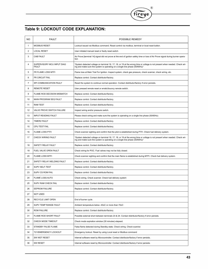
Table 9: LOCKOUT CODE EXPLANATION:
NO FAULT POSSIBLE REMEDY
1 MODBUS RESET Lockout issued via Modbus command. Reset control via modbus, terminal or local reset button.
2 LOCAL RESET User initiated manual reset or faulty reset switch.
3 CAB FAULT Air Prove [terminal 14] signal did not prove at the end of ignition safety time or loss of Air Prove signal during burner opera-tion
4 SUPERVISORY MCU INPUT DIAG FAULT
“System detected voltage on terminal 16, 17, 18, or 19 at the wrong time or voltage is not present when needed. Check wir-ing and make sure the system is operating on a single line phase (50/60Hz)”
5 FR FLAME LOSS MTFI Flame loss at Main Trial For Ignition. Inspect system, check gas pressure, check scanner, check wiring, etc.
6 FR CIRCUIT FAIL Replace control. Contact distributor/factory.
7 SPI COMMUNICATION FAULT Reset the system to continue normal operation. Contact distributor/factory if error persists.
8 REMOTE RESET User pressed remote reset or erratic/bouncy remote switch.
9 FLAME ROD DECISION MISMATCH Replace control. Contact distributor/factory.
10 MAIN PROGRAM SEQ FAULT Replace control. Contact distributor/factory.
11 RAM TEST Replace control. Contact distributor/factory.
12 VALVE PROVE SWITCH FAILURE Inspect wiring and/or pressure switch.
13 INPUT READING FAULT Please check wiring and make sure the system is operating on a single line phase (50/60Hz)
14 TIMER2 FAULT Replace control. Contact distributor/factory.
15 CPU TEST FAIL Replace control. Contact distributor/factory.
16 FLAME LOSS PTFI Check scanner sighting and confirm that the pilot is established during PTFI. Check fuel delivery system.
17 CHECK WIRING FAULT “System detected voltage on terminal 16, 17, 18, or 19 at the wrong time or voltage is not present when needed. Check wir-ing and make sure the system is operating on a single line phase (50/60Hz)”
18 SAFETY RELAY FAULT Replace control. Contact distributor/factory.
19 FUEL VALVE OPEN FAULT Check wiring for POC. Fuel valves may not be fully closed.
20 FLAME LOSS MTFI Check scanner sighting and confirm that the main flame is established during MTFI. Check fuel delivery system.
21 SAFETY RELAY WELDING FAULT Replace control. Contact distributor/factory.
22 SUPV SELF-TEST Replace control. Contact distributor/factory.
23 SUPV CS ROM FAIL Replace control. Contact distributor/factory.
24 FLAME LOSS AUTO Check wiring. Check scanner. Check fuel delivery system
25 SUPV RAM CHECK FAIL Replace control. Contact distributor/factory.
26 EEPROM FAILURE Replace control. Contact distributor/factory.
27 NOT USED
28 RECYCLE LIMIT OPEN End of burner cycle.
29 SUPV TEMP RANGE FAULT Ambient temperature below -40oC or more than 70oC
30 ROM FAILURE Replace control. Contact distributor/factory.
31 FLAME ROD SHORT FAULT Possible external short between terminals 23 & 24. Contact distributor/factory if error persists.
32 CHECK MODE TIMEOUT Check mode expiration window (30 minutes) elapsed.
33 STANDBY FALSE FLAME False flame detected during Standby state. Check wiring. Check scanner.
34 T21/EMERGENCY LOCKOUT Emergency lockout. Reset by using Local reset or Modbus command
35 SW WDT RESET Internal software reset by Microcontroller. Contact distributor/factory if error persists.
36 SW RESET Internal software reset by Microcontroller. Contact distributor/factory if error persists.

44
The above list provides error code explanations to help people in the field respond more effectively to issues that arise.
37 INPUTS WAITING TIME FAULT System was unable to satisfy combustion air switch test and/or proof of closure during a burner sequence. Check wiring. Check air-flow switch.
38 SUPV SW WDT RESET Internal software reset by Microcontroller. Contact distributor/factory if error persists.
39 SUPV SW RESET Internal software reset by Microcontroller. Contact distributor/factory if error persists.
40 HARDWARE RESET Replace control. Contact distributor/factory if error persists.
41 SUPV HARDWARE RESET Replace control. Contact distributor/factory if error persists.
42 MAIN LOOP STUCK FAULT Replace control. Contact distributor/factory.
43 SUPV LOOP STUCK FAULT Replace control. Contact distributor/factory.
44 SUPV TIMER2 FAULT Replace control. Contact distributor/factory.
45 MAIN AC PEAK MISSING FAULT Check Mains voltage. Contact distributor/factory.
46 SUPV AC PEAK MISSING FAULT Check Mains voltage. Contact distributor/factory.
47 UV PULSE INPUT MISSMATCH Replace control. Contact distributor/factory.
48 SUPERVISORY MCU ADC FAULT Replace control. Contact distributor/factory.
49 MAIN MCU ADC FAULT Replace control. Contact distributor/factory.
50 IGNITION FEEDBACK FAULT System detected voltage on terminal 16 at the wrong time or voltage is not present when needed. Check wiring and make sure grounding is adequate.
51 PILOT FEEDBACK FAULT System detected voltage on terminal 17 at the wrong time or voltage is not present when needed. Check wiring and make sure grounding is adequate.
52 MAINP FEEDBACK FAULT System detected voltage on terminal 19 at the wrong time or voltage is not present when needed. Check wiring and make sure grounding is adequate.
53 FEEDBACK WAITING TIME EXPIRE Loss of actuator feedback for more than 10 minutes. Check wiring. Check modulation equipment.
54 MAIND FEEDBACK FAULT System detected voltage on terminal 18 at the wrong time or voltage is not present when needed. Check wiring and make sure grounding is adequate.
55 INTERRUPT DIAG FAULT Replace control. Contact distributor/factory.
56 UV FALSE FLAME ERROR False flame detected before Ignition. Check wiring. Check scanner. Make sure grounding is adequate.
57 FR FALSE FLAME ERROR False flame detected before Ignition. Check wiring. Check scanner. Make sure grounding is adequate.
58 OPEN FEEDBACK READING FAULT System detected voltage on terminal 8 at the wrong time or voltage is not present when needed. Check wiring and make sure grounding is adequate.
59 ADJACENT PIN SHORT FAULT Replace control. Contact distributor/factory.
60 LOCAL RESET DEBOUNCE FAULT Local reset button held for more than 10 seconds or reset button is stuck.
61 POC OPEN FAULT Fuel valve is open at the wrong time OR check wiring
62 STRONG UV FLAME FAULT Scanner too close to flame. Add distance between scanner and flame OR use orifice to reduce field of view.
63 SPI CRC FAULT Replace control. Contact distributor/factory
NO FAULT POSSIBLE REMEDY

®
NOTICEWhen Fireye products are combined with equipment manufactured by others and/or integrated intosystems designed or manufactured by others, the Fireye warranty, as stated in its General Terms andConditions of Sale, pertains only to the Fireye products and not to any other equipment or to thecombined system or its overall performance.
WARRANTIESFIREYE guarantees for one year from the date of installation or 18 months from date of manufactureof its products to replace, or, at its option, to repair any product or part thereof (except lamps andphotocells) which is found defective in material or workmanship or which otherwise fails to conformto the description of the product on the face of its sales order. THE FOREGOING IS IN LIEU OFALL OTHER WARRANTIES AND FIREYE MAKES NO WARRANTY OF MERCHANT-ABILITY OR ANY OTHER WARRANTY, EXPRESS OR IMPLIED. Except as specificallystated in these general terms and conditions of sale, remedies with respect to any product or partnumber manufactured or sold by Fireye shall be limited exclusively to the right to replacement orrepair as above provided. In no event shall Fireye be liable for consequential or special damages ofany nature that may arise in connection with such product or part.
Ordering Information: Part No. FEBP230UVFR-S3