Hazard connected to railway tunnel construction in karstic area ...
Upload
dinhkhuongCategory
view
228download
4
MICROPILING IN KARSTIC ROCK: NEW CMFF FOUNDATION SOLUTION APPLIED AT THE SANITA FACTORY
Marc Ballouz1, Ph.D. Eng’g (94’ Texas A&M University)
Director of the International Institute for Geotechnics and Materials, i IGM s.a.r.l, Beirut, Lebanon Assistant Professor, Lebanese University -UL- Branch II, Roumieh, Lebanon Assistant Professor, Lebanese American University -LAU- Byblos, Lebanon
ABSTRACT
The new Sanita factory is a 2 story factory warehouse covering an area of 10,000 m2 located in Zouk-Mosbeh, Lebanon. The warehouse is composed of 140 reinforced concrete columns supporting a one way pre-stressed concrete slab designed to carry 25 kN/m2 of industrial live load plus a future steel structure. The soil substratum consists of 1 to 4 m of silt on top of the bedrock. The bedrock is hard karstic limestone with cavities and fissures. Because of the karstic nature of the rock, the original design called for a strip foundation on top of the rock with a maximum allowable bearing pressure of 400 kPa. Combined Micropiles and Footing Foundation, CMFF, is a new foundation system that was created by the International Institute for Geotechnics and Materials, iIGM, and implemented as an alternative solution for this particular project. This new system was designed utilizing a finite element model. There were two major concerns regarding this solution. The first concern was with respect to the load-settlement performance of the micropile in the karstic terrain. The second concern was to prove the advantages of the CMFF system considering the particular conditions of the project. Two static load tests were performed on the micropiles with different methods. The results of the tests permitted modeling the soil/structure interactive foundation system. CMFF in karst offered many technical advantages over classical methods. A cost saving of about 40% was also accomplished in the foundation system without compromising safety. This paper summarizes the results of the load tests and the advantages of CMFF in this particular project. The paper also presents the different phases of the foundation system by covering the design details, construction aspects, performance evaluation, and cost analysis.
INTRODUCTION
Project Description The project consists or removing 3 adjacent warehouses and installing a new
modern factory: Sanita. The Sanita factory is part of an international industrial group, INDEVCO group. The factory is rectangular in shape, 165x60 meters, covering an area of about 10,000m2. The structure would be composed of 2 floor levels: The first level is a concrete structure, 5m high covered by a prestressed concrete slab, capable of carrying industrial live loads of 25 kN/m2, and bearing on 140 concrete columns (20 rows on 7 axes). The top floor is a metallic warehouse structure resting on 3 column axes (2 sides and 1 middle) spanning 30m on each side.
Karst Formation The site is located in Zouk Mosbeh village, about 20 km North of Beirut city.
The Geological map of the Zouk region according to L. Dubertret, (1955), is given in Fig. 1. The geological formation in this region is a Quaternary deposit of silt and Clay on top of the Tertiary sedimentary bedrock, Miocene marly and calcareous limestone, “Helvetien” formation (m2b). This bedrock is known, as found, to have karstic formations with large cavities, cracks and crevices.
The nearest known fault to the site is the secondary Dbaiye fault, about 2 km to the south (see Fig. 1). It should be noted that the borehole logs performed on site
do not represent any sudden shift in the soil layers. This indicates that there isn’t any obvious faulting activity within the site. A total of 14 exploratory boreholes were drilled on site. As shown in Fig. 2, the site exploration revealed 2 main soil layers underneath an existing 150 to 200mm concrete slab-on-grade. Permanent groundwater table is very deep; surface seeping water however, accumulates for 3 to 4 days within the silty soil on top of the bedrock after heavy rains. This was evident on site during the construction phase in the winter of 2003. Such seepage activity is worth worrying about in a karstic formation.
FIG.1. Geologic Map of Zouk, Lebanon FIG. 2. Soil Substratum
Structural Data Footings were divided in 5 different cases based on column loads as given by Table 1 below. The foundation substructure was built monolithically even at the location of the expansion joints. Joints were planned in the superstructure. The foundation will be designed to carry vertical concentric loads. Other horizontal and moment loads are resisted by other structural elements like passive side resistance, grade beams, shear walls, etc…
Table 1. Applied Column Loads for Each Footing Case Footing
Case Column Condition Applied Load
(kN) Number of Columns
1 Corner Column with Steel Structure Above
1150 4
2 Side Column with Steel Structure Above
2300 38
3 Side Column without Steel Structure Above
1660 6
4 Central Column with Steel Structure Above
4600 18
5 Central Column without Structure Above
3320 54

Geotechnical Requirements When the soil stratum is a karstic rock formation with a thin soil cover (1 to 4 m), the choice of the foundation system would be financially and technically critical particularly for large projects like the one in question. The challenges of foundation selection in Karstic terrain were discussed for a case history presented by Brinker, F. (2004). The foundation recommendations in the soil report called for:
• removal of the soil cover to avoid sinkholes, • conducting a cavity search under each bearing column, • considering some provisional grouting to close cracks and fissures in the
karstic formation under the columns, • reducing the actual bearing pressure on the fractured rock with
qall=400kPa if shallow foundations are to be used • suggesting a modulus of subgrade reaction ks=80,000 kN/m3 estimated by
a Plate Load test performed at the bedrock surface • Avoiding large diameter piles as a foundation option, since column loads
were not relatively high. Also, drilling in rock is slow and costly After reviewing the geotechnical requirements above, the structural engineer decided to go for a strip foundation and considered the reduced bearing capacity. The strip foundations were placed in the long direction of the factory connecting the short span (8.5m) of the columns (see Fig. 4.a). A total of 7 strip foundations were planned. Each strip foundation had to be excavated to the bedrock level (1 to 4m deep), with a width of 2.2m and a thickness of 1m. The idea was to connect all columns to a rigid foundation that is capable of “bridging” over cavity problem areas as illustrated in Fig. 4.a, treating the rock as a weaker matrix of rock and soil. When bidding on the project, the author found that this solution would be unpractical and time consuming, making room to other cost effective and innovative ideas. The alternative solution proposed by the author and illustrated in Fig. 4.b, consists of installing micropiles under spread footings resting within the karstic rock. This combined Micropile and footing Foundation, abbreviated by CMFF, turned out to be a suitable option
FIG. 4. Possible Foundation Systems

COMBINED MICROPILE AND FOOTING FOUNDATION
Background The use of micropiles as a foundation system is relatively recent and became common in North America in the past 15 years. It started in Italy more than 50 years ago with Dr. Fernando Lizzi. Since then the use of this technology has flourished throughout the world, and is nowadays used by almost all serious geotechnical contractors. Despite its good reputation when transferring the load from the weak layer to the strong stratum, it was rarely used fully embedded in competent rock and in conjunction with the footing. In the litterature the use of micropiles in combination with the footing where both the deep and the shallow foundation are working together was rarely reported. The most comprehensive research in this regard was done by FHWA (2000) in the USA and by the FOREVER (FOndations REnforcees VERticalement, June 2004) national research project in France. Large diameter piles reinforcing raft foundations, were discussed and researched by many like Poulos, H.G.(1997 and 2001), Cunha, R.P (2001), and later defined as the CPRF (Combined Pile-Raft Foundation) method by Katzenbach, R, (2001 and 2003). Small diameter micropiles combined with footings bearing on rock, have not been reported yet to the knowledge of the author. Inspired from previous research done with large diameter piles reinforcing raft foundations, the new concept of combining miropiles with spread footing was created in the purpose of solving the foundation problem of the project in question. Usually when rock is encountered almost always shallow foundations are chosen to transmit the structural loads to the bearing soil, even for high-rise buildings. However, when the rock is karstic by nature, a warning sign should be raised. On this particular project the foundation material is karstic rock that represents a foundation soil that can vary from very hard limestone to nothing (cavity) in a very short distance (<1m) and possibly within the same footing. The intriguing selection of a foundation system in karst is a challenge particular to each project as was recently reported by many professionals like Dotson, D.W (2003), Brinker, F.A (2004), and Siegel, T.C (2005). The use of high capacity micropiles to solve foundation problems in karstic formations was successfully adopted and published in recent years by Traylor, RP et al(2002), Dotson, D.W et al (2003), and Uranowski, D. et al (2004). The behavior of micropiles under vertical loads in rock have been recently evaluated by Cushing, A.G(2004). He compared the results of more than 54 tests done on micropiles in rock. It should be noted that at the time of the project in 2002, only 3 years ago, little was known about the behavior of micropiles in rock. Static load tests to determine the behavior of a typical micropile in the present karstic limestone was needed.
Micropile Installation Procedure The procedure for installing a typical micropile at this project is illustrated in Fig. 5. The piles, including the test piles, were drilled with a 6 inch (150mm) DTHH with monitoring to ensure at least 5m of good friction with competent rock. The hole was reinforced with a 4” API steel tube (or casing) with 100mm inner and having a wall thickness of 7mm. The tube is inserted with centralizers all the way to the bottom. A small ½ inch (12mm) diameter, 1m long PVC tube is taped vertically on the steel casing near the top. Initial grout is placed by hand to close the annular space at the pile top. Grouting under low pressure is done from the top center of the tube. The

grout fills the casing all the way down then is forced under pressure from the bottom up to fill the annular space between the steel and the soil. When the grout reaches the top it starts flowing upward via the ½ inch PVC tube as a proof that the pile is filled. The PVC tube is then clogged and grouting continues to indicate a pressure of minimum 5 bars (0.5 MPa). All the karstic cavities and fissures near the pile are thus consolidated. This type of installation is classified as Type B micropile based on IGU grouting method, Global and Unique Injection (Injection Globale et Unique), according to FHWA (2000) guidelines. A total of 386 micropiles were installed at this site including the tested piles.
Static Load Tests on Micropiles A total of 2 static load tests were conducted on site.
SLT1: Load Test 1 (SLT1) was located close to the center of the site. It was performed on a typical pile 6.7m long, during the initial phase of the construction while the old warehouses were being dismantled as shown in Fig. 6.a. The set-up of SLT1 test is also shown in Fig. 6.a, and illustrated in Fig. 7.a. The first micropile to be tested was constructed as described above. Initially the micropile was designed to carry a design load QDL=450kN, about half the ultimate structural capacity. The test load was planned to go up to ultimate. This ultimate load can be determined by structural limit, geotechnical failure, or double the design load, whichever occurs first. The structural ultimate capacity of a 4”metallic tube filled with grout is about Qsult=950kN. The geotechnical ultimate capacity for fractured limestone was based on a skin friction value fs=1100 kPa, recommended by Bruce, D.A et al (2005) for limestone rock; that is the pile in question with 5m of embedment into rock would be expected to fail geotechnically at Qult=2600 kN. Hence, the load for the test was planned to reach Qmax=900 kN, just below the structural ultimate capacity.
It should be noted that during the test, about 1.7m of the micropile was kept free standing, protruding from the ground above the rock face. This helped in avoiding any influence of the top soil, facilitating the test set-up. Also it permitted observing the structural integrity of the pile during the test.
The displacement curve of a standard load test on the first typical pile installed on site is shown in Fig. 8.a. It shows that the micropile was tested to double the design service load, near structural limit, and was not even near the geotechnical failure. It would be wise to say that unlike in soil, in rock the micropile capacity is controlled by structural capacity rather than geotechnical criteria. The stiffness of the micropile according to Fig. 8, with diameter 150mm (6”), reinforced with a 100mm (4”) API steel tube, and embedded 5m into limestone rock was determined to be around Kmicropile=450000 kN/m. For an applied load of 900 kN the micropile exhibited a max total settlement of 2.1mm only, half of which may be due to the elastic compression of the 4 inch free standing part of the pile casing. These findings led to raising the design load capacity from QDL=450kN to QDL=700kN.
SLT 2:The second load test SLT2 was done near the end of the project as a proof test. In an attempt to minimize the cost, this test was inspired from the Osterberg’s technique (Osterberg, 1995) of separating the end bearing from the friction resistance by testing the pile against itself. As illustrated in Fig. 7.b, this was achieved by inserting 2 API tubes within each other; a 3” tube within a 4” tube. The 4” tube represents the outer shell of the reinforcement, with 4 prestressing cable attached by welding near its end bottom. The cables are greased and sheated on most of their length above the welded zone to reach to top. The 3” tube would be greased

on the outside to reduce friction with the inner side of the 4” tube, and is kept protruding at both ends. As shown in Fig. 6.b, , a 4” casing piece, 200mm long would be welded at the bottom end of the 3” tube to regain the same diameter as in a typical micropile (see Fig. 6).
At the top, the set-up is made in such a way as to jack the outer micropile upward while the central tube is pushed with the end bearing downward. By monitoring the movement of each casing tube, the result is obtained as shown in Fig. 8.b.
FIG. 6. View of SLT 1 (Fig. 6.a) and SLT 2 (Fig. 6.b)
FIG. 7. Set-up of Static Load Tests

FIG. 7. Typical Micropile Installation in Sanita Project
FIG. 8. Load vs Displacement Curves for (a) SLT1 & (b) SLT2
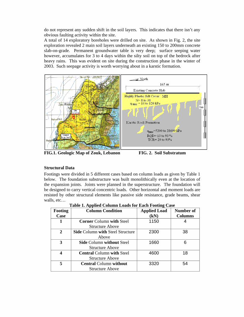
If the load vs. displacement curves for both tests (Fig. 8) are super-imposed, the graphical presentation would look like the one in Fig. 9. From Fig. 9, it would be possible to reconstruct a load transfer curve by matching vertical displacements, and the resulting graph is shown in Fig. 10. This figure shows that the micropile embedded 5m in rock is actually carrying only about 9% of the applied load by end bearing, whereas the rest (91%) are resisted by friction. This explains why most designers neglect the end–bearing resistance when designing micropiles as vertical supports.
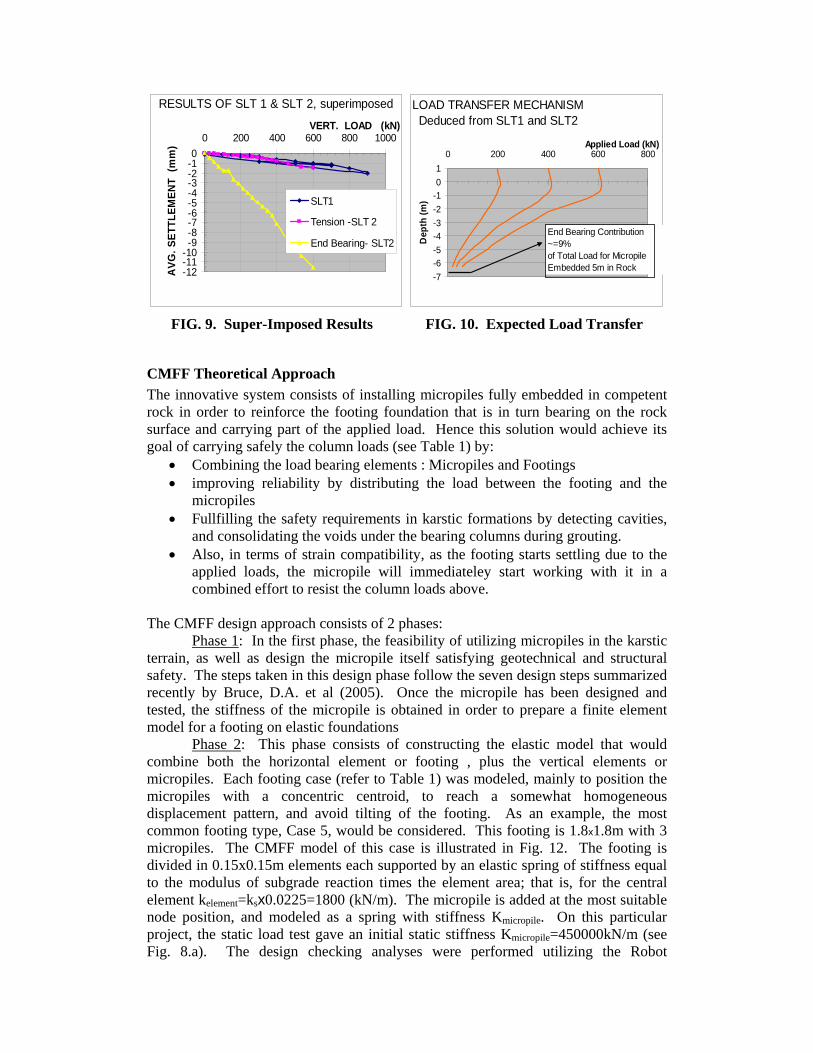
FIG. 9. Super-Imposed Results FIG. 10. Expected Load Transfer
CMFF Theoretical Approach The innovative system consists of installing micropiles fully embedded in competent rock in order to reinforce the footing foundation that is in turn bearing on the rock surface and carrying part of the applied load. Hence this solution would achieve its goal of carrying safely the column loads (see Table 1) by:
• Combining the load bearing elements : Micropiles and Footings • improving reliability by distributing the load between the footing and the
micropiles • Fullfilling the safety requirements in karstic formations by detecting cavities,
and consolidating the voids under the bearing columns during grouting. • Also, in terms of strain compatibility, as the footing starts settling due to the
applied loads, the micropile will immediateley start working with it in a combined effort to resist the column loads above.
The CMFF design approach consists of 2 phases:
Phase 1: In the first phase, the feasibility of utilizing micropiles in the karstic terrain, as well as design the micropile itself satisfying geotechnical and structural safety. The steps taken in this design phase follow the seven design steps summarized recently by Bruce, D.A. et al (2005). Once the micropile has been designed and tested, the stiffness of the micropile is obtained in order to prepare a finite element model for a footing on elastic foundations
Phase 2: This phase consists of constructing the elastic model that would combine both the horizontal element or footing , plus the vertical elements or micropiles. Each footing case (refer to Table 1) was modeled, mainly to position the micropiles with a concentric centroid, to reach a somewhat homogeneous displacement pattern, and avoid tilting of the footing. As an example, the most common footing type, Case 5, would be considered. This footing is 1.8x1.8m with 3 micropiles. The CMFF model of this case is illustrated in Fig. 12. The footing is divided in 0.15x0.15m elements each supported by an elastic spring of stiffness equal to the modulus of subgrade reaction times the element area; that is, for the central element kelement=ksx0.0225=1800 (kN/m). The micropile is added at the most suitable node position, and modeled as a spring with stiffness Kmicropile. On this particular project, the static load test gave an initial static stiffness Kmicropile=450000kN/m (see Fig. 8.a). The design checking analyses were performed utilizing the Robot
-12-11-10-9-8-7-6-5-4-3-2-10
0 200 400 600 800 1000VERT. LOAD (kN)
AVG
. SET
TLEM
ENT
(mm
)
SLT1
Tension -SLT 2
End Bearing- SLT2
RESULTS OF SLT 1 & SLT 2, superimposed LOAD TRANSFER MECHANISMDeduced from SLT1 and SLT2
-7-6-5-4-3-2-101
0 200 400 600 800Applied Load (kN)
Dep
th (m
)
End Bearing Contribution ~=9%of Total Load for Micropile Embedded 5m in Rock

Millenium software. As an example, results for Case 5 footing are presented in Fig. 13. With an applied column load of 3320 kN, the immediate settlements were in the order of 2mm. Also, internal moments are shown in Fig. 13. The average bearing pressure is 170 kPa only. Imagining the footing without the micropiles, the soil pressure would reach 1025 kPa!
FIG. 12. CMFF Model
FIG. 13. Settlement & Moment Distribution in Case 5 Footing
The main difference between CMFF and Micropiling alone is the optimization process of taking full advantage of the carrying capacity of each foundation element. In the past and in the absence of advanced software for modelling this complex soil/structure interaction, CMFF could not be made possible.

ADVANTAGES OF NEW CMFF FOUNDATION SOLUTION
Engineering The engineering advantages for the CMFF solution on this particular project are numerous:
1. Speed: By reducing the quantity of concrete and excavations for the strip foundation , and by providing 3 micropiling rigs on site, a gain in execution time of about 4 weeks was accomplished.
2. Optimization of design: By conducting the load test and a finite element analysis, the foundation system was evaluated and refined in terms of dimensions and reinforcements
3. Improve mobility during construction: Because the CMFF system requires excavation locally under the column, the mobility durig construction of the heavy equipment (cranes, loaders, backhoe, trucks, etc…) was improved
4. Reduce structural and geotechnical risks by creating a foundation system with both vertical and horizontal elements, actively complementing each other, free of hazardous karstic formations underneath
5. Cost reduction: The cost was reduced effectively as shown later, without compromising safety.
6. Salvage existing slab-on-grade: Because the excavation works are localized under the columns, the existing slab-on-grade can be salvaged, cleaned and epoxy coated again for future use. This is also an added cost and time savings.
7. Future expansion: If the piles are planned to be a bit longer, underpinning the factory would in fact be already in place waiting for future expansion by the “Top Down” technique. The piles were indeed installed 8m into the rock, 4 of which would be permanently ready to carry the dead load of the structure above, if a 5m basement is to be excavated and constructed in the future.
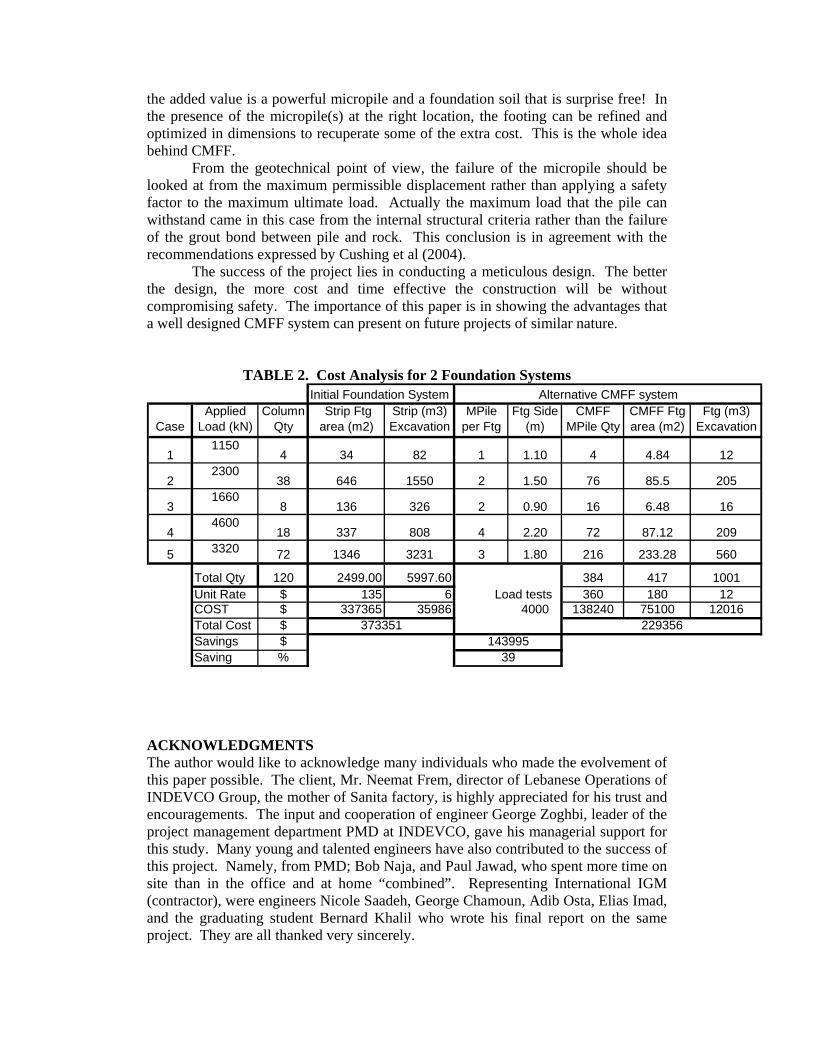
Financial The financial impact on the project can be presented in a tabular form. Table 2 shows a comparison between the initial foundation system and the new CMFF system. A cost saving of about 144,000 $ in addition to 1 month gain in execution time, were accomplished at this site. In addition the cost of pouring a new slab-on-grade was partially saved by refurbishing the old slab. This represents about 40% reduction in cost from the original budget (see Table 2). Actually because of this reduction, the client agreed to increase the micropile length to 8m rather than 5m into the bedrock in as part of a future expansion strategy of the factory. Expansion by underpinning, “top Down” technique, to accommodate an extra basement as pointed out in the advantages above, is now possible with a relatively low budget. CONCLUSION
Some might ask why should we combine micropiles with footings when rock is present ? Why don’t we just enlarge the footing a bit like it has been done in the past and forget about complicating the foundation system? This is true, but not in karstic rock. When the karstic formation presents heterogeneous discontinuities, a cavity search under each column becomes necessary. This is usually done by drilling an investigative hole under the footing. With this hole available, we might as well insert a reinforcement in it. The only added cost is the steel reinforcement; however,
the added value is a powerful micropile and a foundation soil that is surprise free! In the presence of the micropile(s) at the right location, the footing can be refined and optimized in dimensions to recuperate some of the extra cost. This is the whole idea behind CMFF.
From the geotechnical point of view, the failure of the micropile should be looked at from the maximum permissible displacement rather than applying a safety factor to the maximum ultimate load. Actually the maximum load that the pile can withstand came in this case from the internal structural criteria rather than the failure of the grout bond between pile and rock. This conclusion is in agreement with the recommendations expressed by Cushing et al (2004).
The success of the project lies in conducting a meticulous design. The better the design, the more cost and time effective the construction will be without compromising safety. The importance of this paper is in showing the advantages that a well designed CMFF system can present on future projects of similar nature.
TABLE 2. Cost Analysis for 2 Foundation Systems
CaseApplied
Load (kN)Column
Qty Strip Ftg area (m2)
Strip (m3) Excavation
MPile per Ftg
Ftg Side (m)
CMFF MPile Qty
CMFF Ftg area (m2)
Ftg (m3) Excavation
11150
4 34 82 1 1.10 4 4.84 12
22300
38 646 1550 2 1.50 76 85.5 205
31660
8 136 326 2 0.90 16 6.48 16
44600
18 337 808 4 2.20 72 87.12 209
5 3320 72 1346 3231 3 1.80 216 233.28 560
Total Qty 120 2499.00 5997.60 384 417 1001Unit Rate $ 135 6 Load tests 360 180 12COST $ 337365 35986 4000 138240 75100 12016Total Cost $Savings $Saving % 39
Initial Foundation System Alternative CMFF system
373351143995
229356
ACKNOWLEDGMENTS The author would like to acknowledge many individuals who made the evolvement of this paper possible. The client, Mr. Neemat Frem, director of Lebanese Operations of INDEVCO Group, the mother of Sanita factory, is highly appreciated for his trust and encouragements. The input and cooperation of engineer George Zoghbi, leader of the project management department PMD at INDEVCO, gave his managerial support for this study. Many young and talented engineers have also contributed to the success of this project. Namely, from PMD; Bob Naja, and Paul Jawad, who spent more time on site than in the office and at home “combined”. Representing International IGM (contractor), were engineers Nicole Saadeh, George Chamoun, Adib Osta, Elias Imad, and the graduating student Bernard Khalil who wrote his final report on the same project. They are all thanked very sincerely.

REFERENCES: Brinker, F.A, Kazaniwsky, P.W, and Logan, M. (2004), “Case History Illustrating the Challenges of Foundation Design and Construction in Karst Terrain”, Proceedings of the Fifth International Conference on Case Histories in Geotechnical Engineering, New York, NY, April 13-17, 2004
Bruce, D.A., Cadden, A.W., Sabatini, P. J., (2005), “Practical Advice for Foundation Design – Micropiles for Structural Support”, Geotechnical Special Publications 130-142 & GRI-18; Proceedings of the Geo-Frontiers 2005 Congress, January 24.26, 2005, Austin, Texas
Cunha, R.P, Poulos, H.G, (2001), “Investigation of Design Alternatives for a Piled Raft Case History”, Journal of Geotechnical and Geoenvironmental Engineering, Vol. 127, No. 8, August 2001, pp. 635-641
Cushing, A.G., Stonecheck, S.A., Campbell, B.D., Dodds, S.D., (2004), “An Evaluation of the Load-DisplacementBehavior and Load Test Interpretation of Micropiles in Rock”, Proceedings of Fifth International Conference on Case Histories in Geotechnical Engineering, New York, NY, April 13-17, 2004
Dotson, D.W., Tarquinio, F.S., (2003), “A Creative Solution to Problems with Foundation Construction in Karst”, Proceedings of the Ninth Multidisciplinary Conference, September
Dubertret, L. (1955), “Carte Geologique Du Liban”, Ministere Des Travaux Publics, Beyrouth (Geologic Map of Lebanon, Ministry of Public Works)
FHWA, (2000), “Micropile Design and Construction Guidelines”, Implementation Manual, Publication No. FHWA-SA-97-070, 2000
FOREVER, (2004), “FOndations REnforcees VERticalement”, Syntheses of results and recommendations of the national research project on micropiles, Presses de l’ecole nationale des Ponts et Chaussees, France, 16 June, 2004.
Katzenbach, R, Moormann, C, (2001), “Recommendations for the Design and Construction of Piled Rafts”, Proceedings of the Fifteenth International Conference on Soil Mechanics and Geotechnical Engineering, Vol. 2, XVth ICSMGE, Istanbul
Katzenbach, R, Moormann, C, (2003), “Instrumentation and Monitoring of Combined Piled Rafts (CPRF): State-of-the-art Report”, Field Measurements in GeoMechanics, FMGM Symposium, Sept. 2003, Oslo
Oesterberg, J.O., (1995), “The Oesterberg Cell for Load Testing Drilled Shafts and Driven Piles”, U.S. Department of Transportation, Federal Highway Administration, Publcation No. FHWA-SA-94-035
Poulos, H.G., Small, J.C., Ta, L.D, Simha, J., Chen, L., (1997), “Comparison of some Methods for Analysis of Piled Rafts”, Proceedings of the Forteenth International Conference on Soil Mechanics and Foundation Engineering, XIVth ICSMFE, Hamburg, Vol.2, p1119-1124.
Poulos, H.G, (2001), “Piled-raft Foundation: Design and Applications”, Geotechnique 51, No. 2, 95-113 6-10, 2003, Special Publication No. 122, p627-634, Huntsville, AL
ROBOT Millenium, (2004), Structural Analysis Software based on Finite Element Analysis for Structural Design and Engineering Software.
Siegel, T.C., Caskey, J.M., Huckaba, D.A., (2005), “Combination of Ground Improvement Techniques for Support of Shallow Foundations in Karst”, Geotechnical Special Publications 130-142 & GRI-18; Proceedings of the Geo-Frontiers 2005 Congress, January 24.26, 2005, Austin, Texas
Traylor, R.P., Cadden, A.W., Bruce, D.A., (2002), “High Capacity Micropiles in Karst: Cghallenges and Opportunities”, Proceedings of the International Deep Foundations Congress 2002, February 14-16, 2002 Orlando, Florida, p743-759
Uranowski, D.D., Dodds, S.D., Stonecheck, S.A., (2004), “Micropiles in Karstic Dolomite: Similarities and Differences of Two Case Histories”, Proceedings of sessions of the GeoSupport Conference: Innovation and Cooperation in the Geo-Industry, Jan. 29-31, 2004, Orlando, Florida