Micron Power Resistors - audiolabga.com · 7267 Coldwater Canyon, North Hollywood. California 91605...
14
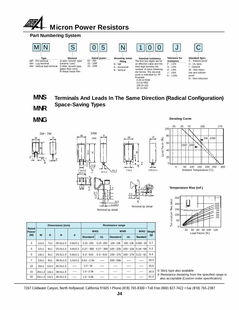
7267 Coldwater Canyon, North Hollywood. California 91605 • Phone (818) 765-8300 • Toll Free (800) 827-7422 • Fax (818) 765-2387 J4 Micron Power Resistors Part Numbering System M N 0 Type MP - Pin terminal MH - Lug terminal MN - Vertical lead terminal 1 0 Nominal resistance The first two digits are for an effective value and the third digit denotes the number of zeros following the former. The decimal point is indicated by “R” Example 0.05 Ω=50M 0.5 Ω=R50 100 Ω=101 2K Ω=202 S Element G-wire -wound type (ceramic core) S-Wire -wound type. (glass fiber core) R-Metal Oxide Film Rated power 02 - 2W 10 - 10W 15 - 15W 0 5 Mounting metal fitting N - Nill A - Horizontal B - Vertical N Tolerance for resistance F - ±1% G - ±2% H - ±3% J - ±5% K - ±10% J Standard Spec. C - Solvent-proof U - UL-spec. I - General W - Non-induc- tive and solvent- proof N - Non-inductive C Terminals And Leads In The Same Direction (Radical Configuration) Space-Saving Types MNS MNR MNG Rated Power (W) 2 3 5 7 10 15 20 W 11±1 12±1 13±1 13±1 16±1 20±1.2 20±1.2 D 7±1 8±1 9±1 9±1 12±1 13±1 13±1 d 0.8±0.1 0.8±0.1 0.8±0.1 1.0±0.1 ___ ___ ___ H 20.5±1.5 25.0±1.5 25.5±1.5 38.5±1.5 35.0±1.5 38.0±1.5 45.0±1.5 Standard 0.15,200 0.27,360 0.3,510 0.51,1.5k 1.0,1k 1.0,2.0k 1.0,3.0k UL 0.15,200 0.27,360 0.3,510 ___ ___ ___ ___ UL 100,13k 100,22k 100,27k ___ ___ ___ ___ S t a n d a rd 0.082,33 0.18,68 0.22,91 ___ ___ ___ ___ Standard 100,13k 100,22k 100,27k 200,56k ___ ___ ___ Weight (g) 3.7 5.3 6.4 10.2 15.5 30.0 41.0 Resistance range MNS MNR MNG 5 ±2 -1 W D 2W,7W d W W 8 D D 10W 10W 3±1.2 7.5±1 3.81±0.1 7.5±0.8 16±1.2 t0.5 1.1±0.1 R1.5 0.5 1.5 1.0 R 3 . 8 1 1.1 Terminal tip detail Terminal tip detail ❇ Stick type also available ❇ Resistance deviating from the specified range is also acceptable (Custom-order specification) 20 40 60 80 100 120 Load Factor (%) 250 200 150 100 50 0 20W 10W 15W 7W 5W 3W 2W 0 50 100 150 200 250 300 Ambient Temperature (°C) 100 80 60 40 20 0 Measuring point -25 25 70 155 275 2W,10W 15W,20W Temperature Rise (ref.) Derating Curve Dimensions (mm)
Transcript of Micron Power Resistors - audiolabga.com · 7267 Coldwater Canyon, North Hollywood. California 91605...
7267 Coldwater Canyon, North Hollywood. California 91605 • Phone (818) 765-8300 • Toll Free (800) 827-7422 • Fax (818) 765-2387
J4
Micron Power ResistorsPart Numbering System
M N 0
Ty p eMP - Pin terminalMH - Lug terminalMN - Vertical lead terminal
1 0
Nominal re s i s t a n c eThe first two digits are foran effective value and thet h i rd digit denotes thenumber of zeros followingthe former. The decimalpoint is indicated by “R” E x a m p l e0.05 Ω=50M0.5 Ω=R50100 Ω=1012K Ω=202
S
E l e m e n tG - w i re -wound type(ceramic core) S - W i re -wound type.(glass fiber core )R-Metal Oxide Film
Rated power02 - 2W10 - 10W15 - 15W
0 5
Mounting metalf i t t i n g
N - NillA - HorizontalB - Ve r t i c a l
NTolerance forre s i s t a n c eF - ± 1 %G - ± 2 %H - ±3%J - ± 5 %K - ±10%
JS t a n d a rd Spec.C - Solvent-pro o fU - UL-spec.I - GeneralW - Non-induc-tive and solvent-p ro o fN - Non-inductive
C
Terminals And Leads In The Same Direction (Radical Configuration)Space-Saving Ty p e s
MNS
MNR
MNG
RatedPower
(W)
2
3
5
7
10
15
20
W
11±1
12±1
13±1
13±1
16±1
20±1.2
20±1.2
D
7±1
8±1
9±1
9±1
12±1
13±1
13±1
d
0.8±0.1
0.8±0.1
0.8±0.1
1.0±0.1
___
___
___
H
20.5±1.5
25.0±1.5
25.5±1.5
38.5±1.5
35.0±1.5
38.0±1.5
45.0±1.5
Standard
0.15,200
0.27,360
0.3,510
0.51,1.5k
1.0,1k
1.0,2.0k
1.0,3.0k
UL
0.15,200
0.27,360
0.3,510
___
___
___
___
UL
100,13k
100,22k
100,27k
___
___
___
___
S t a n d a rd
0.082,33
0.18,68
0.22,91
___
___
___
___
Standard
100,13k
100,22k
100,27k
200,56k
___
___
___
Weight(g)
3.7
5.3
6.4
10.2
15.5
30.0
41.0
Resistance range
MNS MNR MNG
5±2-1
W D
2W,7W
d
WW
8
D D10W
10W
3±1.27.5±1 3.81±0.17.5±0.8
16±1.2
t0.51.1±0.1
R1.5
0.5
1.51.0
R3 . 8 1
1.1
Terminal tip detailTerminal tip detail
Stick type also available Resistance deviating from the specified range is
also acceptable (Custom-order specification)
20 40 60 80 100 120Load Factor (%)
250
200
150
100
50
0
20W10W15W7W5W3W2W
0 50 100 150 200 250 300Ambient Temperature (°C)
100
80
60
40
20
0
Measuring point
-25 25 70 155 275
2W,10W
15W,20W
Temperature Rise (ref.)
Derating Curve
Dimensions (mm)
MVS
MVR
0 50 100 150 200 250 300Ambient Temperature (°C)
100
80
60
40
20
0
-25 25 70 155 275
2W,10W
15W,20W
Derating CurveTemperature Rise (ref.)
20 40 60 80 100 120Load Factor (%)
150
120
90
60
30
0
Measuring pointL1
L2 L3
L4
W1
W12
W3
dW2
20W15W
10W
7W
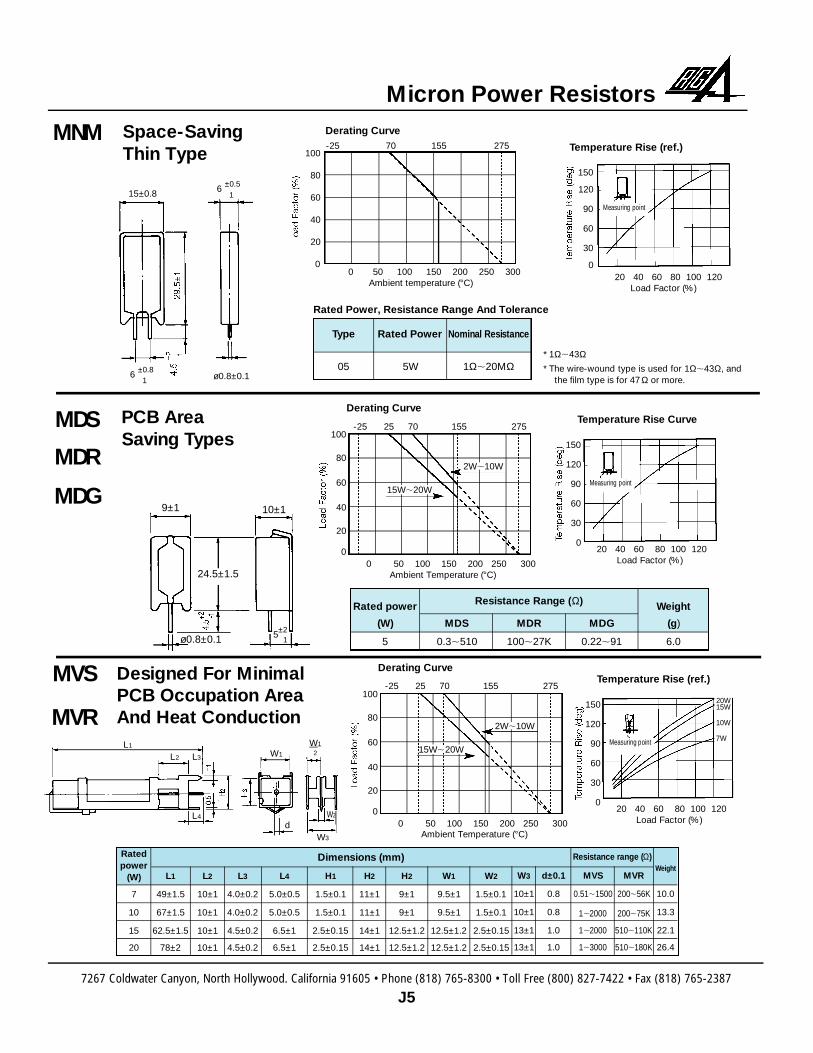
Designed For MinimalPCB Occupation Are aAnd Heat Conduction
7267 Coldwater Canyon, North Hollywood. California 91605 • Phone (818) 765-8300 • Toll Free (800) 827-7422 • Fax (818) 765-2387
J5
Micron Power Resistors
PCB Area Saving Ty p e s
MDS
MDR
MDG
0 50 100 150 200 250 300Ambient Temperature (°C)
100
80
60
40
20
0
-25 25 70 155 275
2W,10W
15W,20W
Derating CurveTemperature Rise Curve
Temperature Rise (ref.)
0 50 100 150 200 250 300Ambient temperature (°C)
100
80
60
40
20
0
Derating Curve-25 70 155 275
20 40 60 80 100 120Load Factor (%)
150
120
90
60
30
0
Measuring point
ø0.8±0.1
15±0.8 6 ±0.51
6 ±0.81
Rated Power, Resistance Range And Tolerance
Type
05
Rated Power
5W
Nominal Resistance
1Ω,20MΩ* 1Ω,43Ω* The wire-wound type is used for 1Ω,43Ω, and
the film type is for 47 Ω or more.
9±1 10±1
24.5±1.5
ø0.8±0.1 5±21
20 40 60 80 100 120Load Factor (%)
150
120
90
60
30
0
Measuring point
Rated power
(W)
5
Weight
(g)
6.0
MDS
0.3,510
MDR
100,27K
MDG
0.22,91
Resistance Range (Ω)
Ratedpower
(W)
7
10
15
20
L1
49±1.5
67±1.5
62.5±1.5
78±2
L2
10±1
10±1
10±1
10±1
L3
4.0±0.2
4.0±0.2
4.5±0.2
4.5±0.2
L4
5.0±0.5
5.0±0.5
6.5±1
6.5±1
H1
1.5±0.1
1.5±0.1
2.5±0.15
2.5±0.15
H2
11±1
11±1
14±1
14±1
H2
9±1
9±1
12.5±1.2
12.5±1.2
W1
9.5±1
9.5±1
12.5±1.2
12.5±1.2
W2
1.5±0.1
1.5±0.1
2.5±0.15
2.5±0.15
W3
1 0 ± 1
1 0 ± 1
1 3 ± 1
1 3 ± 1
d±0.1
0.8
0.8
1.0
1.0
We i g h t
10.0
13.3
22.1
26.4
MVS
0.51,1500
1,2000
1,2000
1,3000
MVR
200,56K
200,75K
510,110K
510,180K
Resistance range (Ω)Dimensions (mm)
Space-SavingThin Type
MNM
7267 Coldwater Canyon, North Hollywood. California 91605 • Phone (818) 765-8300 • Toll Free (800) 827-7422 • Fax (818) 765-2387
J6
Micron Power ResistorsMSS
MSR
MSG
MGS
MGR
MGG
0 50 100 150 200 250 300Ambient Temperature (°C)
100
80
60
40
20
0
Derating Curve-25 70 155 275
0 50 100 150 200 250 300Ambient Temperature (°C)
100
80
60
40
20
0
-25 25 70 155 275
3W,10W
15W,20W
Derating Curve
0 50 100 150 200 250 300Ambient Temperature (°C)
100
80
60
40
20
0
-25 25 70 155 275
2W,10W
2W,10W
15W,20W
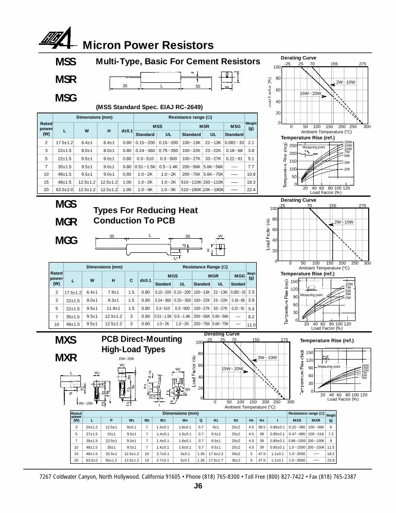
Derating CurveMulti-Type, Basic For Cement Resistors
(MSS Standard Spec. EIAJ RC-2649)
Types For Reducing Heat Conduction To PCB
PCB Dire c t - M o u n t i n gHigh-Load Ty p e s
MXS
MXR
Ratedpower
(W)
2
3
5
7
10
15
20
Weight(g)
2.1
3.8
5.1
7.7
10.8
18.3
22.4
L
17.5±1.2
22±1.5
22±1.5
35±1.5
48±1.5
48±1.5
63.5±2.0
W
6.4±1
8.0±1
9.5±1
9.5±1
9.5±1
12.5±1.2
12.5±1.2
H
6.4±1
8.0±1
9.0±1
9.0±1
9.0±1
12.5±1.2
12.5±1.2
Standard
0.15,200
0.24,360
0.3,510
0.51,1.5K
1.0,2K
1.0,2K
1.0,3K
UL
0.15,200
0.75,350
0.3,500
0.5,1.4K
1.0,2K
1.0,2K
1.0,3K
UL
22,13K
23,22K
33,27K
5.6K,56K
5.6K,75K
150,110K
10K,180K
Standard
100,13K
100,22K
100,27K
200,56K
200,75K
510,110K
510,180K
Standard
0.082,33
0.18,68
0.22,91___
___
___
___
d±0.1
0.80
0.80
0.80
0.80
0.80
1.00
1.00
Dimensions (mm) Resistance range (Ω)
MSS MSR MSG
Ratedpower
(W)
2
3
5
7
10
Weight(g)
2.3
3.9
5.4
8.2
11.0
L
17.5±1.2
22±1.5
22±1.5
35±1.5
48±1.5
W
6.4±1
8.0±1
9.5±1
9.5±1
9.5±1
C
1.5
1.5
1.5
3
3
H
7.9±1
9.3±1
11.9±1
12.5±1.2
12.5±1.2
S t a n d a rd
0 . 1 5,2 0 0
0 . 2 4,3 6 0
0 . 3,5 1 0
0 . 5 1,1 . 5 K
1 . 0,2 K
U L
0 . 1 5,2 0 0
0 . 2 5,3 5 0
0 . 3,5 0 0
0 . 5,1 . 4K
1.0,2K
UL
22,13K
23,22K
33,27K
5.6K,56K
5.6K,75K
Standard
100,13K
100,22K
100,27K
200,56K
200,75K
S t a n d a rd
0 . 0 8 2,3 3
0 . 1 8,6 8
0 . 2 2,9 1_ _ _
_ _ _
d±0.1
0.80
0.80
0.80
0.80
0.80
Dimensions (mm) Resistance Range (Ω)
MGS MGR MGG
Ratedp o w e r
(W)
3
5
7
10
15
20
L
24±1.2
27±1.5
35±1.5
48±1.5
48±1.5
63.5±2
P
12.5±1
15±1
22.5±1
35±1
32.5±1
50±1.2
W1
9±0.1
9.5±1
9.5±1
9.5±1
12.5±1.2
12.5±1.2
W3
1.4±0.1
1.4±0.1
1.4±0.1
1.4±0.1
2.7±0.1
2.7±0.1
W4
1.6±0.1
1.6±0.1
1.6±0.1
1.6±0.1
3±0.1
3±0.1
H1
9±1
9.5±1
9.5±1
9.5±1
17.5±1.2
17.5±1.7
H2
25±2
25±2
25±2
25±2
30±2
30±2
t
0.85±0.1
0.85±0.1
0.85±0.1
0.85±0.1
1.1±0.1
1.1±0.1
MXS
0.22,390
0.47,680
0.68,1000
1.0,1500
1.0,2000
1.0,3000
MXR
100,39K
100,51K
200,100K
200,150K___
___
H3
4.5
4.5
4.5
4.5
5
5
We i g h t( g )
6
7.2
9
11.5
18.2
23.9
H4
38.5
39
39
39
47.5
47.5
W2
7
7
7
7
10
10
Q
0.7
0.7
0.7
0.7
1.35
1.35
Resistance range (Ω)Dimensions (mm)
35 L 35 W
35 L 35 W
L W1
W1W2
W3
W4
t0.5
tR
P
3 W,1 0 W
1 5 W,2 0 W
20 40 60 80 100 120Load Factor (%)
Temperature Rise (ref.)
250
200
150
100
50
0
20W15W10W7W5W
3W
2W
Measuring point
20 40 60 80 100 120Load Factor (%)
Temperature Rise (ref.)
150
120
90
60
30
0
10W7W5W3W2W
Measuring point
20 40 60 80 100 120Load Factor (%)
Temperature Rise (ref.)
150
120
90
60
30
0
20W15W10W7W5W3W
Measuring point
7267 Coldwater Canyon, North Hollywood. California 91605 • Phone (818) 765-8300 • Toll Free (800) 827-7422 • Fax (818) 765-2387
J7
Micron Power Resistors
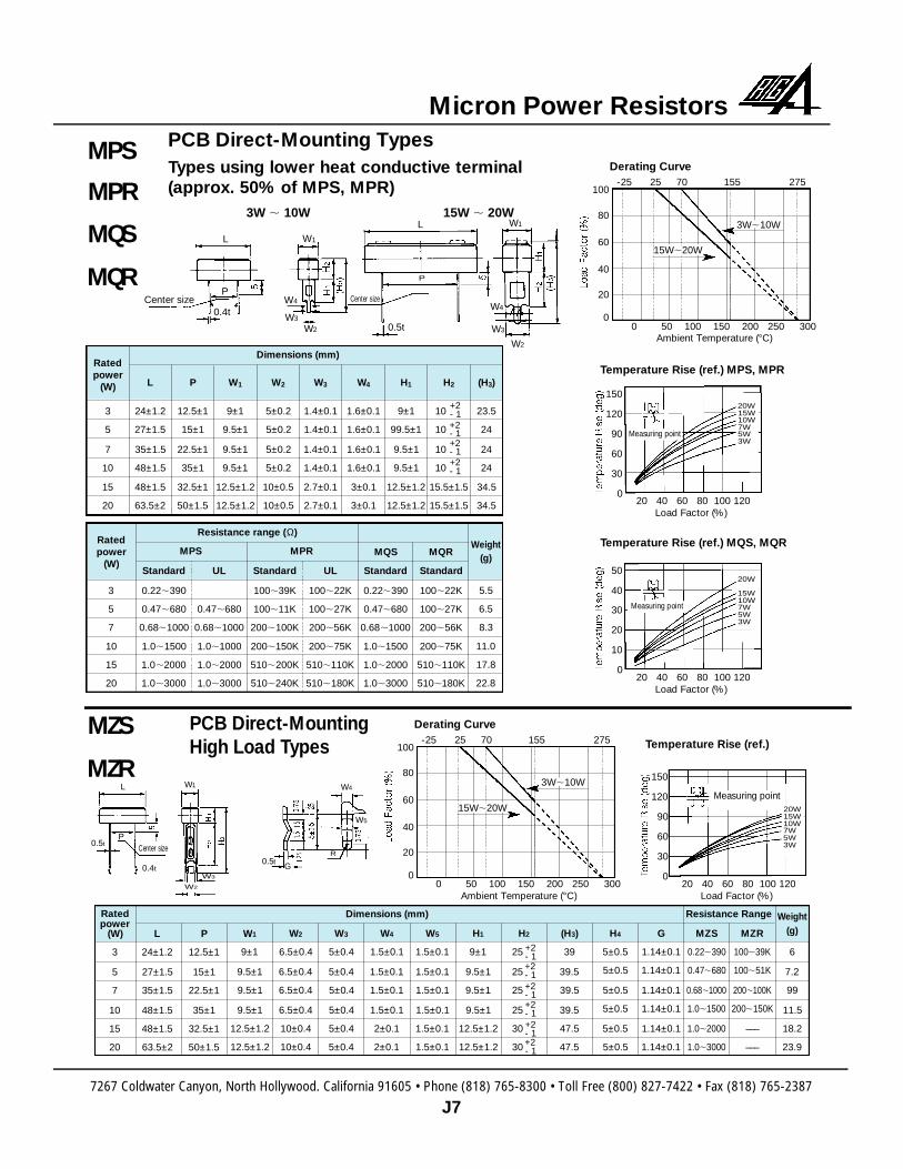
MPS
MPR
MQS
MQR
MZS
MZR
0 50 100 150 200 250 300Ambient Temperature (°C)
100
80
60
40
20
0
-25 25 70 155 275
3W,10W
15W,20W
Derating Curve
0 50 100 150 200 250 300Ambient Temperature (°C)
100
80
60
40
20
0
-25 25 70 155 275
3W,10W
15W,20W
Derating Curve
Temperature Rise (ref.)
PCB Direct-Mounting Types
PCB Direct-Mounting High Load Ty p e s
Types using lower heat conductive terminal(approx. 50% of MPS, MPR)
3W , 10W 15W , 20W
20 40 60 80 100 120Load Factor (%)
150
120
90
60
30
0
Measuring point20W15W10W7W5W3W
Temperature Rise (ref.) MPS, MPR
20 40 60 80 100 120Load Factor (%)
150
120
90
60
30
0
Measuring point
20W15W10W7W5W3W
Temperature Rise (ref.) MQS, MQR
20 40 60 80 100 120Load Factor (%)
50
40
30
20
10
0
Measuring point
20W
15W10W7W5W3W
Ratedpower
(W)
3
5
7
10
15
20
L
24±1.2
27±1.5
35±1.5
48±1.5
48±1.5
63.5±2
P
12.5±1
15±1
22.5±1
35±1
32.5±1
50±1.5
W1
9±1
9.5±1
9.5±1
9.5±1
1 2 . 5 ± 1 . 2
1 2 . 5 ± 1 . 2
W2
5±0.2
5±0.2
5±0.2
5±0.2
10±0.5
10±0.5
W3
1.4±0.1
1.4±0.1
1.4±0.1
1.4±0.1
2.7±0.1
2.7±0.1
W4
1.6±0.1
1.6±0.1
1.6±0.1
1.6±0.1
3±0.1
3±0.1
H1
9±1
99.5±1
9.5±1
9.5±1
1 2 . 5 ± 1 . 2
1 2 . 5 ± 1 . 2
H2
10
10
10
10
1 5 . 5 ± 1 . 5
1 5 . 5 ± 1 . 5
(H3)
23.5
24
24
24
34.5
34.5
+2- 1+2- 1+2- 1+2- 1
Dimensions (mm)
Ratedpower
(W)
3
5
7
10
15
20
Standard
0.22,390
0.47,680
0.68,1000
1.0,1500
1.0,2000
1.0,3000
UL
0.47,680
0.68,1000
1.0,1000
1.0,2000
1.0,3000
Standard
100,39K
100,11K
200,100K
200,150K
510,200K
510,240K
UL
100,22K
100,27K
200,56K
200,75K
510,110K
510,180K
MQS
Standard
0.22,390
0.47,680
0.68,1000
1.0,1500
1.0,2000
1.0,3000
MQR
Standard
100,22K
100,27K
200,56K
200,75K
510,110K
510,180K
Weight(g)
5.5
6.5
8.3
11.0
17.8
22.8
MPS
Resistance range (Ω)
MPR
Ratedpower
(W)
3
5
7
10
15
20
L
24±1.2
27±1.5
35±1.5
48±1.5
48±1.5
63.5±2
P
12.5±1
15±1
22.5±1
35±1
32.5±1
50±1.5
W1
9±1
9.5±1
9.5±1
9.5±1
12.5±1.2
12.5±1.2
W2
6.5±0.4
6.5±0.4
6.5±0.4
6.5±0.4
10±0.4
10±0.4
W3
5±0.4
5±0.4
5±0.4
5±0.4
5±0.4
5±0.4
W4
1.5±0.1
1.5±0.1
1.5±0.1
1.5±0.1
2±0.1
2±0.1
W5
1.5±0.1
1.5±0.1
1.5±0.1
1.5±0.1
1.5±0.1
1.5±0.1
H1
9±1
9.5±1
9.5±1
9.5±1
12.5±1.2
12.5±1.2
H2
25
25
25
25
30
30
(H3)
39
39.5
39.5
39.5
47.5
47.5
Weight(g)
6
7.2
99
11.5
18.2
23.9
H4
5±0.5
5±0.5
5±0.5
5±0.5
5±0.5
5±0.5
G
1.14±0.1
1.14±0.1
1.14±0.1
1.14±0.1
1.14±0.1
1.14±0.1
MZS
0.22,390
0.47,680
0.68,1000
1.0,1500
1.0,2000
1.0,3000
MZR
100,39K
100,51K
200,100K
200,150K
___
___
+2- 1+2- 1+2- 1+2- 1+2- 1+2- 1
Dimensions (mm) Resistance Range
L W1
W1
W2
W3
W4
W2
W3
W4
P
L
P
0.4t
0.5t
Center size Center size
L W1
W3
W2
W4
W5
P
0.4t0.5t
G
R
0.5tCenter size
7267 Coldwater Canyon, North Hollywood. California 91605 • Phone (818) 765-8300 • Toll Free (800) 827-7422 • Fax (818) 765-2387
J8
Micron Power Resistors
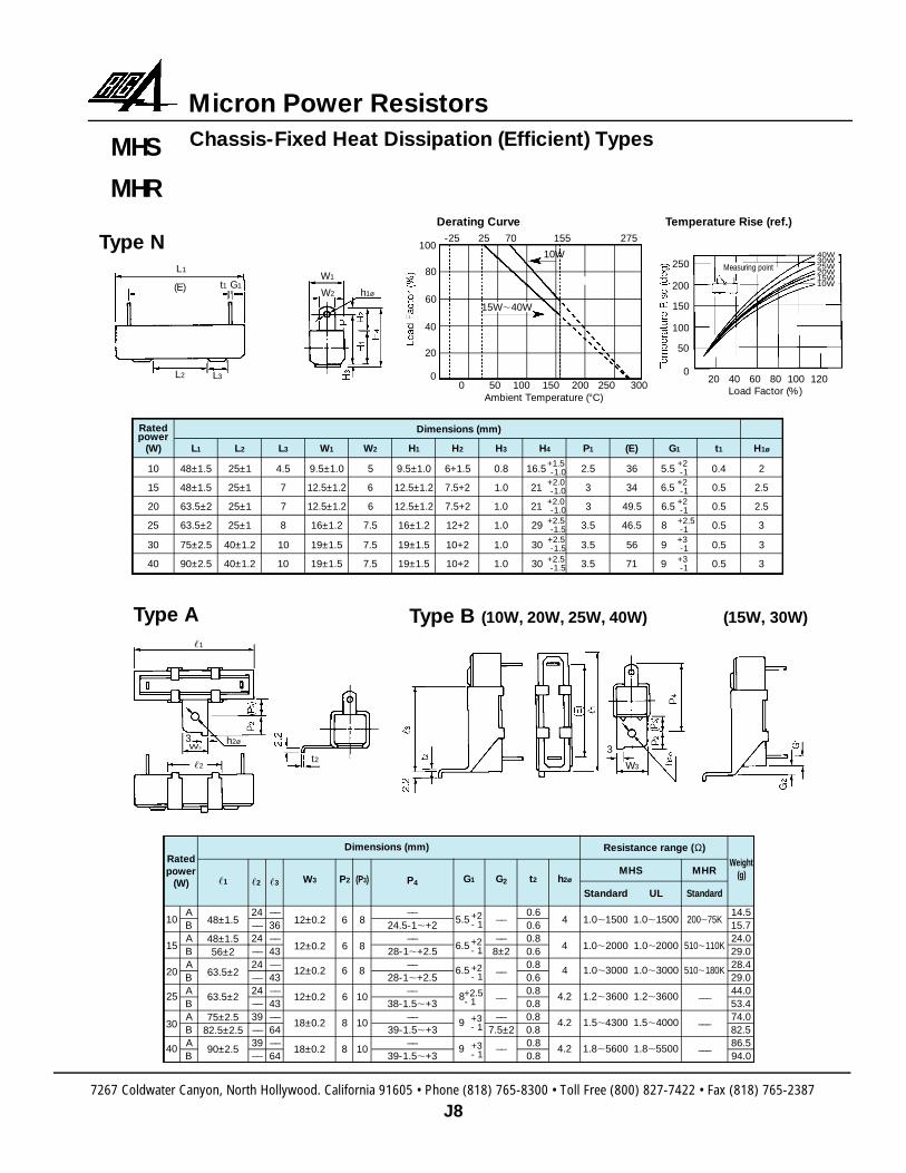
MHS
MHR
Chassis-Fixed Heat Dissipation (Efficient) Types
Type N
Type A Type B (10W, 20W, 25W, 40W) (15W, 30W)
0 50 100 150 200 250 300Ambient Temperature (°C)
100
80
60
40
20
0
-25 25 70 155 275
10W
15W,40W
Derating Curve Temperature Rise (ref.)
Ratedpower
(W)
10
15
20
25
30
40
L1
48±1.5
48±1.5
63.5±2
63.5±2
75±2.5
90±2.5
L2
25±1
25±1
25±1
25±1
40±1.2
40±1.2
L3
4.5
7
7
8
10
10
W1
9.5±1.0
12.5±1.2
1 2 . 5 ± 1 . 2
16±1.2
19±1.5
19±1.5
W2
5
6
6
7.5
7.5
7.5
H3
0.8
1.0
1.0
1.0
1.0
1.0
P1
2.5
3
3
3.5
3.5
3.5
(E)
36
34
49.5
46.5
56
71
t1
0.4
0.5
0.5
0.5
0.5
0.5
H1ø
2
2.5
2.5
3
3
3
H4
16.5
21
21
29
30
30
H1
9.5±1.0
12.5±1.2
1 2 . 5 ± 1 . 2
16±1.2
19±1.5
19±1.5
H2
6+1.5
7.5+2
7.5+2
12+2
10+2
10+2
+1.5-1.0
+2.0-1.0
+2.0-1.0
+2.5-1.5
+2.5-1.5
+2.5-1.5
G1
5.5
6.5
6.5
8
9
9
+2-1
+2-1
+2-1+2.5-1
+3-1
+3-1
Dimensions (mm)
Ratedp o w e r
(W)
10
15
20
25
30
40
ABABABABABAB
24__
24__
24__
24__
39__
39__
__
36__
43__
43__
43__
64__
64
0.60.60.80.60.80.60.80.80.80.80.80.8
14.515.724.029.028.429.044.053.474.082.586.594.0
P4
__
24.5-1,+2__
28-1,+2.5__
28-1,+2.5__
38-1.5,+3__
39-1.5,+3__
39-1.5,+3
G2
__
__
8±2
__
__
__
7.5±2__
,1
48±1.5
48±1.556±2
63.5±2
63.5±2
75±2.582.5±2.5
90±2.5
W3
12±0.2
12±0.2
12±0.2
12±0.2
18±0.2
18±0.2
G1
5.5
6.5
6.5
8
9
9
h2ø
4
4
4
4.2
4.2
4.2
Standard
1.0,1500
1.0,2000
1.0,3000
1.2,3600
1.5,4300
1.8,5600
S t a n d a rd
2 0 0,7 5 K
5 1 0,1 1 0 K
5 1 0,1 8 0 K
_ _ _
_ _ _
_ _ _
UL
1.0,1500
1.0,2000
1.0,3000
1.2,3600
1.5,4000
1.8,5500
P2
6
6
6
6
8
8
(P3)
8
8
8
10
10
10
Weight(g)
Resistance range (Ω)
MHS MHRt2
Dimensions (mm)
,2 ,3
+2- 1
+2- 1
+2- 1
+2.5- 1
+3- 1
+3- 1
L1
h1ø
W1
W2(E) t1 G1
L2 L3
,1
,2
h2ø
W3
3
t23
20 40 60 80 100 120Load Factor (%)
250
200
150
100
50
0
40W30W25W20W15W10W
Measuring point
W3
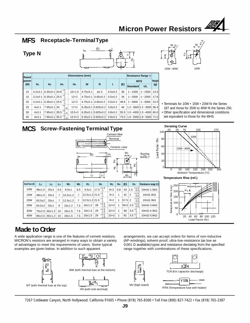
MFS
Type N
0 50 100 150 200 250 300Ambient Temperature (°C)
100
80
60
40
20
0
-25 25 70 155 275
10W
15W,40W
Derating Curve
Temperature Rise (ref.)
20 40 60 80 100 120Load Factor (%)
250
200
150
100
50
0
40W30W25W20W15W10W
Measuring point
• Terminals for 10W • 15W • 20W fit the Series187 and those for 25W to 40W fit the Series 250.
• Other specification and dimensional conditionsa re equivalent to those for the MHS.
MCS
Made to OrderA wide application range is one of the features of cement re s i s t o r s .MICRON’s resistors are arranged in many ways to obtain a varietyof advantages to meet the requirements of users. Some typicalexamples are given below. In addition to such apparent
arrangements, we can accept orders for items of non-inductive(AP-windings), solvent-proof, ultra-low-resistance (as low as0,001 Ω available) types and resistance deviating from the specifiedrange together with combinations of these specifications.
Receptacle-Terminal Type
Screw-Fastening Terminal Type
Ratedpower
(W)
10
15
20
25
30
40
H1
3.2±0.1
3.2±0.1
3.2±0.1
4±0.1
4±0.1
4±0.1
H2
6.35±0.1
6.35±0.1
6.35±0.1
7.95±0.1
7.95±0.1
7.95±0.1
W
4.75±0.1
4.75±0.1
4.75±0.1
6.35±0.1
6.35±0.1
6.35±0.1
t
0.5±0.2
0.5±0.2
0.5±0.2
0.8±0.2
0.8±0.2
0.8±0.2
Standard
1,1500
1,2000
1,3000
1.2,3600
1.5,4000
1.8,5000
UL
1,1500
1,2000
1,3000
1.2,3500
1.5,4000
1.8,5000
R
ø1.3
0.65±0.2
0.65±0.2
0.825±0.2
0.825±0.2
0.825±0.2
H4
10+1.5
12+2
12+2
17+2
15.5+2
15.0+2
H3
20.8
25.5
25.5
34
35.5
35.5
(E)
36
34
49.5
46
55.5
70.5
Weight(g)
13.5
17.8
22.0
36.4
60.0
71.5
Resistance Range Ω
MFS
Dimensions (mm)
+2-1
+2-1
+2-1
+3-1.5
+3-1.5
+3-1.5
Rated Power (W)
10W
15W
20W
25W
30W
40W
L1
48±1.5
48±1.5
63.5±2
63.5±2
75±2.5
90±2.5
L2
25±1
25±1
25±1
25±1
40±1.2
40±1.2
W1
9.5±1
12.5±1.2
12.5±1.2
16±1.2
19±1.5
19±1.5
H1
9.5±1
12.5±1.2
12.5±1.2
16±1.2
19±1.5
19±1.5
Resistance range (Ω)
10mΩ-1.5kΩ
10mΩ-2kΩ
10mΩ-3kΩ
10mΩ-3.6kΩ
10mΩ-4.3kΩ
10mΩ-5.6kΩ
H3
8+2
9+2
9+2
12+2
10+2
10+2
H4
0.8
1
1
1
1
1
(E)
43
42
57.5
56.5
66
81
H2
17.5
21.5
21.5
28
29
29
W2
6.5
7
7
7.5
7.5
7.5
L3
4.5
7
7
8
10
10
+1.5-1
+2-1
+2-1
+2.5-1.5
+2.5-1.5
+2.5-1.5
G1
1.5
2
2
2.5
3.5
3.5
+1.5-0.5
+1.5-0.5+1.5-0.5
+1.5-0.5
+2-1
+2-1
(E) t
15W,40W
W W
10W
(E) G1
L2 L3
Ceramic case
Cement filter
Terminal
W2
W1
BurringM4X0.7
MT (with thermal fuse at the top)
MM (with thermal fuse at the bottom)
HH (with mid-terminal)
MV (high stand)
TCR (For capacitor discharge)
RTM (Temperature fuse with heater)
7267 Coldwater Canyon, North Hollywood. California 91605 • Phone (818) 765-8300 • Toll Free (800) 827-7422 • Fax (818) 765-2387
J9
Micron Power Resistors
7267 Coldwater Canyon, North Hollywood. California 91605 • Phone (818) 765-8300 • Toll Free (800) 827-7422 • Fax (818) 765-2387
J10
Micron Power Resistors
Part Numbering System
F R 2
Fusing re s i s t o r
2 R
Nominal re s i s t a n c eThe first two digits are foran effective value and thet h i rd digit denotes thenumber of zeros followingthe former. The decimalpoint is indicated by “R”
N
E l e m e n tN: Metal oxide film
type WW: Wire - w o u n d
t y p e
Rated power14 - 1/4W12 - 1/2W02 - 2W10 - 10W
0 2
Mounting metalf i t t i n g
N - Nill
NTolerance forre s i s t a n c eJ - ± 5 %K - ±10%
JU L
U
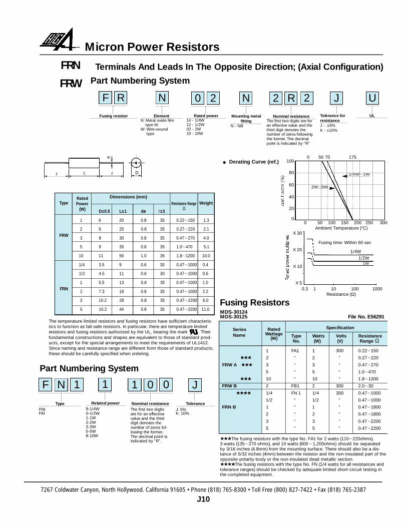
Terminals And Leads In The Opposite Direction; (Axial Configuration)FRN
FRW
0 50 100 150 200 250 300Ambient Temperature (°C)
100
80
60
40
20
0
0 50 70 175
1/4W,1W
2W,5W
• Derating Curve (ref.)
Fusing ResistorsM D S - 3 0 1 2 4MDS-30125 File No. E56291
Dimensions (mm)
D±0.5 L±1 dø ,±3
1 6 20 0.8 35 0.22,150 1.3
2 6 25 0.8 35 0.27,220 2.1
3 8 30 0.8 35 0.47,270 4.0
5 9 35 0.8 35 1.0,470 5.1
10 11 56 1.0 35 1.8,1200 10.0
1/4 3.5 9 0.6 30 0.47,1000 0.4
1/2 4.5 11 0.6 30 0.47,1000 0.6
1 5.5 13 0.8 35 0.47,1000 1.0
2 7.3 18 0.8 35 0.47,1000 2.2
3 10.2 28 0.8 35 0.47,2200 6.0
5 10.2 44 0.8 35 0.47,2200 11.0
RatedPower
(W)
The temperature limited resistors and fusing resistors have sufficient characteris-tics to function as fail-safe resistors. In particular, there are temperature limitedresistors and fusing resistors authorized by the UL, bearing the mark . Theirfundamental constructions and shapes are equivalent to those of standard prod-ucts, except for the special arrangements to meet the requirements of UL1412.Since naming and resistance range are different from those of standard products,these should be carefully specified when ordering.
The fusing resistors with the type No. FA1 for 2 watts (110,220ohms), 3 watts (135,270 ohms), and 10 watts (600 ,1,200ohms) should be separatedby 3/16 inches (4.8mm) from the mounting surface. There should also be a dis-tance of 5/32 inches (4mm) between the resistor and the non-insulated part of theopposite-polarity body or the non-insulated dead metallic section.The fusing resistors with the type No. FN (1/4 watts for all resistances andtolerance ranges) should be checked by adequate limited short-circuit testing inthe completed equipment.
Specification
Type Watts Volts ResistanceNo. (W) (V) Range Ω
1 FA1 1 300 0.22,150
2 “ 2 “ 0.27,220
FRW A 3 “ 3 “ 0.47,270
5 “ 5 “ 1.0,470
10 “ 10 “ 1.8,1200
FRW B 2 FB1 2 300 2.0,30
1/4 FN 1 1/4 300 0.47,1000
1/2 “ 1/2 “ 0.47,1000
FRN B 1 “ 1 “ 0.47,1800
2 “ 2 “ 0.47,1800
3 “ 3 “ 0.47,2200
5 “ 5 “ 0.47,2200
SeriesName
RatedWa t t a g e
(W)
Ty p eF N IFA I
Nominal re s i s t a n c eThe first two digitsa re for an eff e c t i v evalue and the thirddigit denotes thenumber of zeros fol-lowing the former.The decimal point isindicated by “R”.
Related power9 - 1 / 4 W0 - 1 / 2 W1 - 1 W2 - 2 W3 - 3 W5 - 5 W8 - 1 0 W
To l e r a n c eJ: 5%K: 10%
J
L, , D
Fusing time: Within 60 sec
1/4W
1/2W1W
0.3 1 10 100 1000Resistance (Ω)
X 30
X 20
X 10
X 5
Part Numbering System
Ω
F N 1 1 1 0 0
Resistance Range WeightType
FRW
FRN
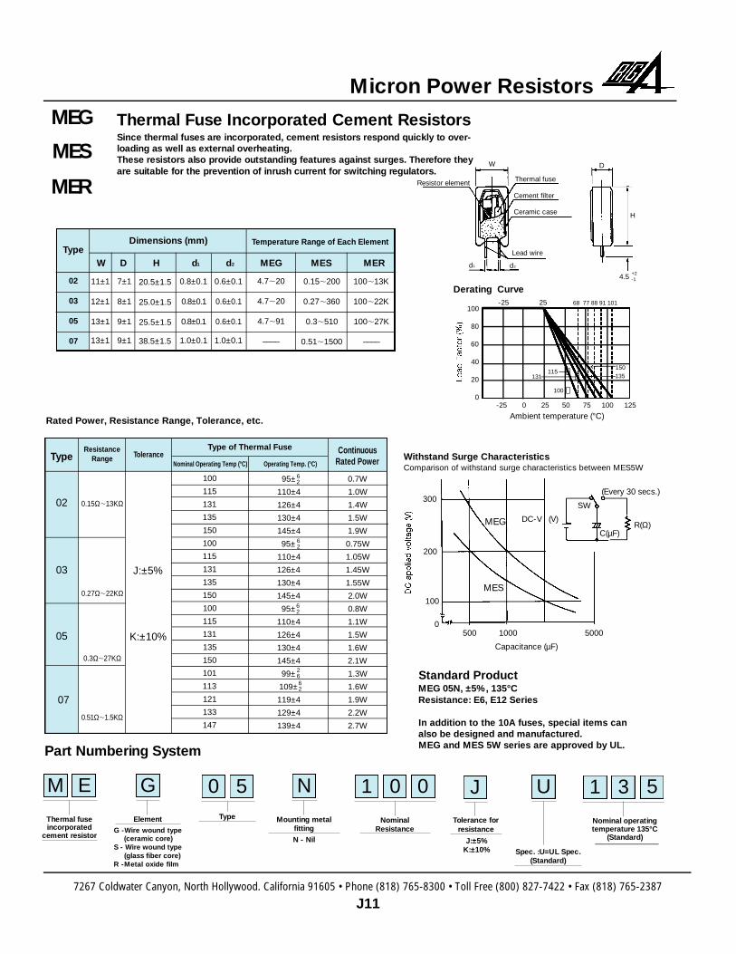
Thermal Fuse Incorporated Cement ResistorsSince thermal fuses are incorporated, cement resistors respond quickly to over-loading as well as external overheating.These resistors also provide outstanding features against surges. There f o re theya re suitable for the prevention of inrush current for switching re g u l a t o r s .
MEG
MES
MER
Part Numbering System
M E
Thermal fusei n c o r p o r a t e d
cement re s i s t o r
1 0 0 5
N o m i n a lR e s i s t a n c e
1 3
Nominal operatingt e m p e r a t u re 135°C
( S t a n d a rd )
0 5Ty p eE l e m e n t
G
Mounting metalf i t t i n g
N
Tolerance forre s i s t a n c e
J U
Spec. :U=UL Spec.( S t a n d a rd )
Type
02
03
05
07
11±1
12±1
13±1
13±1
20.5±1.5
25.0±1.5
25.5±1.5
38.5±1.5
0 . 8 ± 0 . 1
0 . 8 ± 0 . 1
0 . 8 ± 0 . 1
1 . 0 ± 0 . 1
0.6±0.1
0.6±0.1
0.6±0.1
1.0±0.1
7±1
8±1
9±1
9±1
Type
02
03
05
07
Tolerance
J:±5%
K:±10%
ResistanceRange
0.15Ω,13KΩ
0.27Ω,22KΩ
0.3Ω,27KΩ
0 . 5 1 Ω,1 . 5 K Ω
Nominal Operating Temp (°C) Operating Temp. (°C)
Type of Thermal Fuse
Rated Power, Resistance Range, Tolerance, etc.
100
115
131
135
150
100
115
131
135
150
100
115
131
135
150
101
113
121
133
147
95±
110±4
126±4
130±4
145±4
95±
110±4
126±4
130±4
145±4
95±
110±4
126±4
130±4
145±4
99±
109±
119±4
129±4
139±4
62
62
62
62
26
0.7W
1.0W
1.4W
1.5W
1.9W
0.75W
1.05W
1.45W
1.55W
2.0W
0.8W
1.1W
1.5W
1.6W
2.1W
1.3W
1.6W
1.9W
2.2W
2.7W
ContinuousRated Power
4.7,20
4.7,20
4.7,91
––––
100,13K
100,22K
100,27K
––––
0.15,200
0.27,360
0.3,510
0.51,1500
W D H d1 d2 MEG MES MER
Dimensions (mm) Temperature Range of Each Element
J:±5%K:±10%
N - NilG -Wire wound type
(ceramic core)S - Wire wound type
(glass fiber core)R -Metal oxide film
Standard ProductMEG 05N, ±5%, 135°CResistance: E6, E12 Series
In addition to the 10A fuses, special items can also be designed and manufactured.MEG and MES 5W series are approved by UL.
100
80
60
40
20
0-25 0 25 50 75 100 125
-25 25 68 77 88 91 101
Ambient temperature (°C)
115 →
100 →
131 → 135150
Derating Curve
W
Resistor element Thermal fuse
Cement filter
Ceramic case
Lead wire
d1 d2
D
H
4.5+2-1
300
200
100
500 1000 50000
MES
MEG
Capacitance (µF)
DC-V (V)R(Ω)
C(µF)
SW
(Every 30 secs.)
Withstand Surge CharacteristicsComparison of withstand surge characteristics between MES5W
7267 Coldwater Canyon, North Hollywood. California 91605 • Phone (818) 765-8300 • Toll Free (800) 827-7422 • Fax (818) 765-2387
J11
Micron Power Resistors

7267 Coldwater Canyon, North Hollywood. California 91605 • Phone (818) 765-8300 • Toll Free (800) 827-7422 • Fax (818) 765-2387
J12
Micron Power Resistors
S c rew-Fastening Terminal Types (For High To rq u e )Please refer to MDS-21211 for more detailed information.
Making the best use of the fail-safe feature off e red by cement resistors, this typehas been developed for use in industrial equipment and general applications. Thistype of resistor is provided with M4 (M5) screw fastening terminals. A pneumatics c rewdriver is available for fastening.
MBP
MBC
MBS
Part Numbering System
M B
Generic name
1 0 0
R e s i s t a n c e
4 0E x t e rnal shapeResistor element
S
Mounting metalf i t t i n g
A
To l e r a n c e
K I
Distinction ofI n d u c t i v e / n o n - I n d u c t i v e
MBR
1 2 3 4 5 6 7 8 9 10 11
L
h1
ø1
,1
W
,3
,2
,3
,3
h2
h2
h1
h
,2
,1
W
L
ø1
W
L
ø1
,2
,1
(E)
H1
H2
M
H2
H1
(E)M
h2
H2H1
(E)M
MB40 MB30 MB20,MB15
ININININININININININININININININ
–15W15W15W9W
11W5W——
20W20W20W15W15W7W——
30W30W30W24W24W15W——
40W40W40W32W32W20W—
—15mΩ,160mΩ
0.14Ω,0.9Ω0.14Ω,0.9Ω0.7Ω,1.2kΩ0.6Ω,120Ω100Ω,27kΩ
——
5.5mΩ,200mΩ0.19Ω,1.3Ω0.19Ω,1.3Ω0.8Ω,2kΩ
0.8Ω,220Ω220Ω,55kΩ
——
5mΩ,160mΩ0.16Ω,1.8Ω0.16Ω,1.8Ω1.2Ω,3.3kΩ0.8Ω,330Ω
500Ω,110kΩ——
5mΩ,0.35Ω0.2Ω,2.6Ω0.2Ω,2.6Ω1.5Ω,5kΩ
1.3Ω,470Ω500Ω,180kΩ
—
P(Band wire)
C(coil)
S(Wirewound)
R(Metal oxide film)
P(Band wire)
C(Coil)
S(Wirewound)
R(Metal oxide film)
P(Band wire)
C(Coil)
S(Wirewound)
R(Metal oxide film)
P(Band wire)
C(Coil)
S(Wirewound)
R(Metal oxide film)
Shape
MB15
MB20
MB30
MB40
Symbol
J
K
Tolerance
±5%
±10%
ToleranceElementConstruction
Inductive/Non-
Inductive
RatedPower
NominalResistance Range
Nominal Resistance Values
L
90±2.5
75±2.5
63.5±2
48±1.5
W
19±1.5
19±1.5
12.5±1.2
12.5±1.2
H1
19±1.5
19±1.5
12.5±1.2
12.5±1.2
Shape
MB40
MB30
MB20
MB15
M
M5xP0.8
M5xP0.8
M4xP0.7
M4xP0.7
H2
31
31
23.5
23.5
+3-1
+2-1
+2-1
+3-1
(E)
58
44
50
35
,1
39
55
36
36
,3
3
3
3
3
,2
18
18
12
12
ø1
4.2
4.2
4
4
h1
8
8
6
6
h2
2.2
2.2
2.2
2.2
Holder PlateThickness
0.8
1.0
1.0
1.0
0 50 100 150 200 250 300
-25 25 70 155 275100
80
60
40
20
0
15W
→15 Wor more
Ambient Temperature (°C)
Derating Curve
External Dimensions
20 40 60 80 100 120
250
200
150
100
50
0
40W
Lead Factor (%)
Temperature Rise (ref.)
30W25W
20W15W
10W
Measuring point
7267 Coldwater Canyon, North Hollywood. California 91605 • Phone (818) 765-8300 • Toll Free (800) 827-7422 • Fax (818) 765-2387
J13
Micron Power Resistors
Part Numbering System
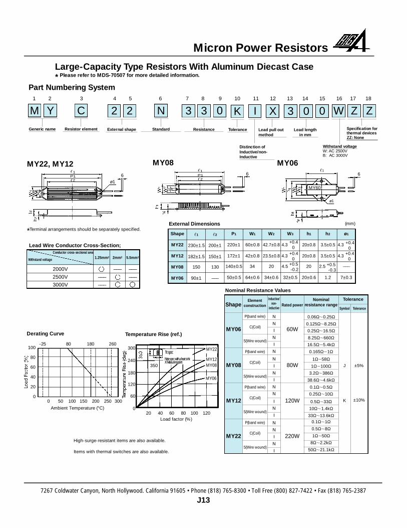
Large-Capacity Type Resistors With Aluminum Diecast Case* Please refer to MDS-70507 for more detailed information.
M Y
Generic name
3 3 0 0
R e s i s t a n c e
3 0
Lead lengthin mm
W Z ZSpecification forthermal devicesZZ: None
Withstand voltageW: AC 2500VB: AC 3000V
2 2
E x t e rnal shapeResistor element
C
S t a n d a rd
N
To l e r a n c e
K I
Lead pull outm e t h o d
X
Distinction ofI n d u c t i v e / n o n -I n d u c t i v e
1 2 3 4 5 6 7 8 9 10 11 12 13 14 15 16 17 18
MY22, MY12
Lead Wire Conductor Cross-Section;
External Dimensions
Nominal Resistance Values
Derating Curve Temperature Rise (ref.)
MY08 MY06,1P1,2
,1P1,2
ø16 6
,1
MY60
6
ø1
*Terminal arrangements should be separately specified.
Ambient Temperature (°C)
Load factor (%)
0 50 100 150 200 2 5 0 3 0 0
-25 80 180 260
20 40 60 80 1 0 0 1 2 0
100
80
60
40
20
0
300
240
180
120
60
0
MY22
350MY12MY08
MY06
High-surge-resistant items are also available.
Items with thermal switches are also available.
Withstand voltage
Conductor cross-sectional area
2000V
2500V
3000V
1.25mm2
___
___
2mm2
___
5.5mm2
___
___
Shape
MY22
MY12
MY08
MY06
,1
230±1.5
182±1.5
150
90±1
P1
220±1
172±1
140±0.5
50±0.5
W1
60±0.8
42±0.8
34
64±0.6
W2
42.7±0.8
23.5±0.8
20
34±0.6
h1
20±0.8
20±0.8
20
20±0.6
h2
3.5±0.5
3.5±0.5
2.5
1.2
W3
4.3
4.3
4.5
32±0.5
,2
200±1
150±1
130
___
+0.40
+0.40
+0.5-0.2
ø1
4.3
4.3
___
7±0.3
+0.40
+0.40
+0.5-0.3
(mm)
Shape
MY06
MY08
MY12
MY22
Rated power
60W
80W
120W
220W
Elementconstruction
P(band wire)
C(Coil)
S(Wire wound)
P(band wire)
C(Coil)
S(Wire wound)
P(band wire)
C(Coil)
S(Wire wound)
P(band wire)
C(Coil)
S(Wire wound)
Nominalresistance range
0.06Ω,0.25Ω0.125Ω,8.25Ω0.25Ω,16.5Ω8.25Ω,660Ω16.5Ω,5.4kΩ0.165Ω,1Ω
1Ω,58Ω1Ω,100Ω
3.2Ω,386Ω38.6Ω,4.6kΩ0.1Ω,0.5Ω0.25Ω,10Ω
0.5Ω,33Ω10Ω,1.4kΩ33Ω,13.6kΩ
0.1Ω,1Ω0.5Ω,8Ω1Ω,50Ω
8Ω,2.2kΩ50Ω,21.1kΩ
J
K
Symbol
±5%
±10%
Tolerance
ToleranceI n d u c t i v e /n o n -
i n d u c t i v e
N
N
I
N
I
N
N
I
N
I
N
N
I
N
I
N
N
I
N
I
1t spcc Note spcc with a heat sink X Measuring point
7267 Coldwater Canyon, North Hollywood. California 91605 • Phone (818) 765-8300 • Toll Free (800) 827-7422 • Fax (818) 765-2387
J14
Micron Power Resistors
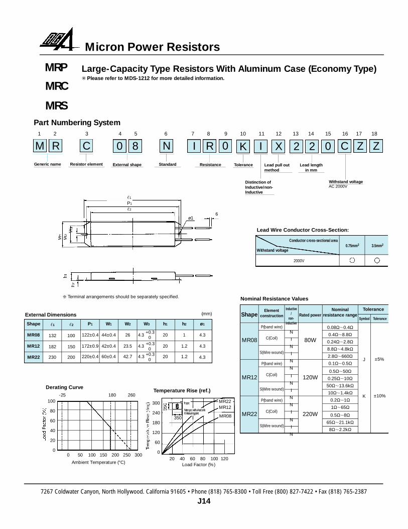
Large-Capacity Type Resistors With Aluminum Case (Economy Ty p e ) Please refer to MDS-1212 for more detailed information.
MRP
MRC
MRSPart Numbering System
M RGeneric name
I R 0 0
R e s i s t a n c e
2 2
Lead lengthin mm
C Z Z
Withstand voltageAC 2000V
0 8
E x t e rnal shapeResistor element
C
S t a n d a rd
N
To l e r a n c e
K I
Lead pull outm e t h o d
X
Distinction ofI n d u c t i v e / n o n -I n d u c t i v e
1 2 3 4 5 6 7 8 9 10 11 12 13 14 15 16 17 18
External Dimensions
Lead Wire Conductor Cross-Section:
Derating CurveTemperature Rise (ref.)
Ambient Temperature (°C) Load Factor (%)
0 50 100 150 200 250 3 0 0
-25 180 260
20 40 60 80 100 120
100
80
60
40
20
0
300
240
180
120
60
0
MR22
350
MR12
MR08
Shape
MR08
MR12
MR22
,1
132
182
230
P1
122±0.4
172±0.9
220±0.4
W1
44±0.4
42±0.4
60±0.4
W2
26
23.5
42.7
h1
20
20
20
h2
1
1.2
1.2
W3
4.3
4.3
4.3
,2
100
150
200
+0.30
+0.30
+0.30
ø1
4.3
4.3
4.3
(mm) Shape
MR08
MR12
MR22
Rated power
80W
120W
220W
Elementconstruction
P(band wire)
C(Coil)
S(Wire wound)
P(band wire)
C(Coil)
S(Wire wound)
P(band wire)
C(Coil)
S(Wire wound)
Nominalresistance range
0.08Ω,0.4Ω0.4Ω,8.8Ω
0.24Ω,2.8Ω8.8Ω,4.8kΩ2.8Ω,660Ω0.1Ω,0.5Ω
0.5Ω,50Ω0.25Ω,10Ω50Ω,13.6kΩ10Ω,1.4kΩ0.2Ω,1Ω1Ω,65Ω
0.5Ω,8Ω65Ω,21.1kΩ8Ω,2.2kΩ
J
K
Symbol
±5%
±10%
Tolerance
Tolerance
Withstand voltage
Conductor cross-sectional are a0 . 7 5 m m2 3 . 5 m m2
2 0 0 0 V
Terminal arrangements should be separately specified. Nominal Resistance Values
Inductive/
non-inductive
N
I
N
I
N
N
I
N
I
N
N
I
N
I
N
,1
P1
,2
ø16
1t spcc
Note spcc with a heat sink X Measuring point
7267 Coldwater Canyon, North Hollywood. California 91605 • Phone (818) 765-8300 • Toll Free (800) 827-7422 • Fax (818) 765-2387
J15
Micron Power Resistors
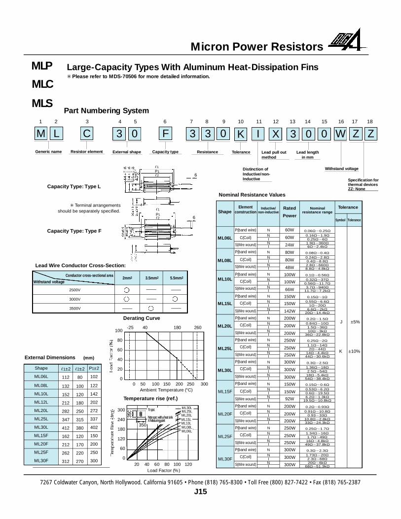
Part Numbering System
M L
Generic name
3 3 0 0
R e s i s t a n c e
3 0
Lead lengthin mm
W Z Z
Withstand voltage
Specification forthermal devicesZZ: None
3 0
E x t e rnal shapeResistor element
C
Capacity type
F
To l e r a n c e
K I
Lead pull outm e t h o d
X
Distinction ofI n d u c t i v e / n o n -I n d u c t i v e
1 2 3 4 5 6 7 8 9 10 11 12 13 14 15 16 17 18
External Dimensions (mm)
Lead Wire Conductor Cross-Section:
Capacity Type: Type L
Capacity Type: Type F
Derating Curve
Temperature rise (ref.)
Ambient Temperature (°C)
Load Factor (%)
0 50 100 150 200 250 300
-25 40 180 260
20 40 60 80 100 120
100
80
60
40
20
0
300
240
180
120
60
0
ML30L
350
ML25LML20L
Withstand voltage
Conductor cross-sectional are a2 m m2 3 . 5 m m2 5 . 5 m m2
2 0 0 0 V
Nominal Resistance Values
3000V
3500V
,1P1,2 6
,1
P1,2 6
2500V
ML15LML10LML08LML06L
Shape
ML06L
ML08L
ML10L
ML12L
ML20L
ML25L
ML30L
ML15F
ML20F
ML25F
ML30F
,1±2
112
132
152
212
282
347
412
162
212
262
312
,2±2
80
100
120
180
250
315
380
120
170
220
270
P1±2
102
122
142
202
272
337
402
150
200
250
300
Shape
ML06L
ML08L
ML10L
ML15L
ML20L
ML25L
ML30L
ML15F
ML20F
ML25F
ML30F
Elementconstruction
P(band wire)
C(Coil)
S(Wire wound)
P(band wire)
C(Coil)
S(Wire wound)
P(band wire)
C(Coil)
S(Wire wound)
P(band wire)
C(Coil)
S(Wire wound)
P(band wire)
C(Coil)
S(Wire wound)
P(band wire)
C(Coil)
S(Wire wound)
P(band wire)
C(Coil)
S(Wire wound)
P(band wire)
C(Coil)
S(Wire wound)
P(band wire)
C(Coil)
S(Wire wound)
P(band wire)
C(Coil)
S(Wire wound)
P(band wire)
C(Coil)
S(Wire wound)
NNINI
NNINI
NNINI
NNINI
NNINI
NNINI
NNINI
NNINI
NNINI
NNINI
NNINI
0.3Ω,2.3Ω1.73Ω,20Ω2.3Ω,68Ω20Ω,6kΩ
68Ω,51.3kΩ
0.25Ω,1.7Ω1.34Ω,16Ω1.7Ω,49Ω16Ω,4.8kΩ49Ω,37.8kΩ
0.2Ω,0.93Ω0.91Ω,10.8Ω
0.93,33Ω10.8Ω,2.8kΩ33Ω,24.3kΩ
0.15Ω,0.6Ω0.53Ω,6.2Ω0.6Ω,19.5Ω6.2Ω,1.3kΩ
19.5Ω,10.8kΩ
0.3Ω,2.5Ω1.36Ω,18Ω2.5Ω,54Ω18Ω,5.4kΩ54Ω,38.4kΩ
0.25Ω,2Ω1.1Ω,14Ω2Ω,44Ω
14Ω,4.4kΩ44Ω,30.6kΩ
0.2Ω,1.5Ω0.84Ω,10Ω1.5Ω,36Ω10Ω,3kΩ
36Ω,22.8kΩ
0.15Ω,1Ω0.55Ω,6.6Ω
1Ω,20Ω6.6Ω,2kΩ
20Ω,14.4kΩ
0.1Ω,0.56Ω0.32Ω,37Ω
0.56Ω,11.7Ω3.7Ω,940Ω
11.7Ω,7.2kΩ
0.08Ω,0.4Ω0.24Ω,2.8Ω0.4Ω,8.8Ω2.8Ω,660Ω8.8Ω,4.8kΩ
0.06Ω,0.25Ω0.16Ω,1.9Ω0.25Ω,6Ω1.9Ω,360Ω6Ω,2.4kΩ
Inductive/non-inductive
Nominalresistance range
Rated
Power
60W
60W
24W
80W
80W
48W
100W
100W
66W
150W
150W
142W
200W
200W
200W
250W
250W
250W
300W
300W
300W
150W
150W
92W
200W
200W
200W
250W
250W
250W
300W
300W
300W
Tolerance
Symbol Tolerance
J ±5%
K ±10%
Terminal arrangements should be separately specified.
Large-Capacity Types With Aluminum Heat-Dissipation Fins Please refer to MDS-70506 for more detailed information.
MLP
MLC
MLS
1t spcc
Note spcc with a heat sinkX Measuring point

7267 Coldwater Canyon, North Hollywood. California 91605 • Phone (818) 765-8300 • Toll Free (800) 827-7422 • Fax (818) 765-2387
J16
Micron Power Resistors
Large-Capacity Cement Resistors in Ceramic CaseMOS
Part Numbering System
M O S 1
Generic name
1 0
Nominal re s i s t a n c e
0 6
E x t e rnal shape Mounting fittingsA: horizontalB: vertical
A
To l e r a n c e
KDistinction ofi n d u c t i v e /n o n - i n d u c t i v e
I
This is a series of large-capacity cement resistors contained in non-metalliccases. Since these resistors can be arranged into modules, conventional resistorsof the same classes (large-capacity paint resistors, enameled resistors) can beimmediately replaced with them. They are economically advantageous.
Rated power, size, and resistance range
Temperature rise (ref.)
External appearance and construction
Shape
MO06
MO08
MO10
MO12
Rated power
60W
80W
100W
120W
Nominal Resistance range
2.4Ω,9.1kΩ
3.3Ω,13kΩ
4.3Ω,16kΩ
5.0Ω,20kΩ
Tolerance
J: ±5%
K: ±10%
L1
100±2.5
125±2.5
150±3
175±3
(L2)
69
94
119
144
L3
110,130
135,155
160,180
185,205
L4
140±4
165±4
190±5
215±5
L1
(L2) 0.8 14.7
Cement filler
Terminal
Ceramic case
Holder Resistor element
L3
L4
45 20
+3-1
29±1.7 ø3.57.92±0.1
0 20 40 60 80 100 120Load factor (%)
250
200
150
100
50
0
0 50 100 150 200 250 300Ambient temperature (°C)
100
80
60
40
20
0
100W-120W
60W-80WMeasuring point
Derating curve
-25 25 155 275
Dimensions (mm)
Note: Items for non-inductive spec. (AP wound),Ultra-low-resistances (20m available), and series250 Faston terminals can also be manufactured.
7267 Coldwater Canyon, North Hollywood. California 91605 • Phone (818) 765-8300 • Toll Free (800) 827-7422 • Fax (818) 765-2387
J17
Micron Power Resistors
Part Numbering System
L T R
Generic name A p p e a r a n c e
1
Ty p e
MTe r m i n a l
c o n s t r u c t i o nC: Cord typeF: Frame type
C
Linear temp. range
1: -30°C,+ 5 0 ° C2: -30°C,+ 5 0 ° C3: -30°C,+ 5 0 ° C
3I n t e rc h a n g e a b i l i t ye r ro rF: ±1.0°CG: ±2.0°C
G
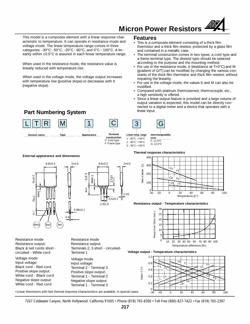
This model is a composite element with a linear response char-acteristic to temperature. It can operate in resistance mode andvoltage mode. The linear temperature range comes in three categories: -30°C,50°C, -20°C,80°C, and 0°C,100°C. A lin-earity within ±0.5°C is assured in each linear temperature range.
When used in the resistance mode, the resistance value is linearly reduced with temperature rise.
When used in the voltage mode, the voltage output increaseswith temperature rise (positive slope) or decreases with it (negative slope).
F e a t u re s• This is a composite element consisting of a thick film
thermistor and a thick film re s i s t o r, protected by a glass film and contained in a metallic case.
• The terminal construction comes in two types; a cord type and a frame terminal type. The desired type should be selected a c c o rding to the purpose and the mounting method.
• For use in the resistance mode, b (resistance at T=0°C) and M(gradient of Ω/T) can be modified by changing the various con-stants of the thick film thermistor and thick film re s i s t o r, withoutimpairing the linearity.
• For use in the voltage mode, the values b and M can also be m o d i f i e d .
• C o m p a red with platinum thermosensor, thermocouple, etc., a high sensitivity is off e re d .
• Since a linear output feature is provided and a large volume ofoutput variation is expected, this model can be directly con-nected to a digital meter and a device that operates with a linear input.
External appearance and dimensions
Resistance modeResistance output:Black & red cords short - circuited - White cord
Voltage modeInput voltage:Black cord - Red cordPositive slope output:White cord - Black cordNegative slope output:White cord - Red cord
Resistance modeResistance output:Terminals 2, 3 short - circuited-Terminal 1
Voltage modeInput voltage:Terminal 2 - Terminal 3Positive slope output:Terminal 1 - Terminal 2Negative slope output:Terminal 1 - Terminal 3
Thermal response characteristics
Resistance output - Temperature characteristics
-30 -20 0 20 40 60 80 100Temperature (C°)
400
300
200
100
0
30
25
20
15
10
5
0 10 20 30 40 50 60 70 80 90 100Temperature difference (%)
Voltage output - Temperature characteristics
-30 -20 0 20 40 60 80 100
1.0
0.8
0.6
0.4
0.2
0
8.8±0.3
0.86±0.1
0.5±0.1
2.5 2.5
0.25
0.5
2±0.5 8.8±0.3 2±0.5
White Black Red
•Linear thermistors with fast thermal response characteristics are available, in special cases.