Micromechanical modeling of crack propagation in nodular ... · Micromechanical modeling of crack...
14
Transcript of Micromechanical modeling of crack propagation in nodular ... · Micromechanical modeling of crack...

Micromechanical modeling of crack
propagation in nodular cast iron with
competing ductile and cleavage failureArticle published in Engineering Fracture Mechanics, 147(2015), 388�397. The
�nal publication is available at www.sciencedirect.com,doi:10.1016/j.engfracmech.2015.06.039
Geralf Hütter, Lutz Zybell, Meinhard Kuna
A micromechanical model is employed to simulate the fracture of nodular cast iron in theductile-brittle transition region. The microstructure is resolved discretely as voids in theprocess zone. Possible cleavage of the intervoid ligaments is modeled by a cohesive zone.This approach captures both the local fracture stress for cleavage and the energy requiredto drive the cleavage crack front thus allowing to simulate all stages of crack initiation andpropagation in the complete ductile-brittle transition region. A comparison with experi-ments from literature shows that the model captures the experimental results qualitativelyand quantitatively.Keywords: ductile-brittle transition; micromechanics; �nite element analysis; cohesive zone;nodular cast iron
1 Introduction
Due to its excellent grindability, cost-e�ective production and good strength and toughness properties,nodular cast iron1 is employed for numerous technical applications, e.g. for gear boxes or nuclear wastecasks. The particular values of strength and fracture toughness depend on the active damage mechanismand thus on temperature. In the range of room temperature nodular cast iron fails by a ductilemechanism like most engineering metals: the relatively weakly bonded nodular graphite particles (whichtypically have a volume fraction of about 10%) debond after low deformations. The thereby createdvoids grow by plastic deformations and coalesce �nally, Figure 1a. The necessary plastic deformationsresult in a high macroscopic fracture toughness. With decreasing temperature the yield stress increasesdue to the lower mobility of dislocations. That is why at lower temperatures the local stress level in themicroligaments between the voids reaches at some point a critical level whereupon grains with favorablyoriented crystallographic planes cleave. Corresponding fracture surfaces are shown in Figure 1c. Thecleavage mechanism dissipates considerable less energy and is thus associated with macroscopicallybrittle behavior. In the ductile-brittle transition region both mechanisms compete as can be seen inFigure 1b.The loss of fracture toughness associated with the transition from ductile failure to cleavage is a
severe problem in many engineering applications. For this reason considerable e�ort has been dedicated
1The material is also known as �ductile cast iron� (DCI). However, in order to avoid confusion with the damage mecha-nisms, this term is not used here.
1
(a) 20 � (b) -40 � (c) -60 �
Figure 1: Fracture surfaces of the ferritic nodular cast iron GJS-400 after tests at di�erent temperatures(courtesy of A. Ludwig and G. Pusch)
.
to the development of models for the ductile-brittle transition. Most of these models were developed forferritic steels. Especially Beremin-type models (Beremin, 1983) are established for evaluating cleavagefailure. In this type of models, cleavage initiation is assumed to coincide with complete failure of thestructure, the so-called �weakest-link assumption�. However, due to its heterogeneous microstructure,in nodular cast iron macroscopically stable crack propagation by cleavage is observed (Baer, 2014;Ludwig et al., 2012; Pusch, 2008; Pusch et al., 2016; Smirnova and Shcheglyuk, 1989). Thus, thismaterial provides a safety reserve which cannot be addressed by the established Beremin-type models.Associated with a macroscopically stable cleavage crack propagation is a lower scatter of the measuredfracture toughness values in the ductile-brittle transition region compared e.g. to ferritic steels. Recently,Baer (2014) formulated the following hypothesis as explanation of this behavior of nodular cast iron:�After initiation, the crack propagates by a cleavage mechanism through the small ferritic matrix areasin between the graphite nodules . . . Each time when the crack runs into the next graphite nodule thecrack tip is blunted signi�cantly due to the spheric shape of the particle and it is more or less arrestedwithin a short time. Thus, a number of microscopic pop-ins are superimposed and cause a macroscopicelastic-plastic appearance of the force-time record�.The aim of the present study is to provide a numerical model that accounts for the individual charac-
teristics of the microstructure of nodular cast iron in the ductile-brittle transition temperature regimeallowing to investigate the mechanisms qualitatively and to provide quantitative predictions for thementioned safety reserve. There are many studies in the literature which deal either with the ductile-brittle transition on the macroscopic scale by Beremin-type models or which resolve the microstructurefor the purely ductile mechanism. Reviews on both classes of models can be found in (Pineau, 2006,2008) and (Benzerga and Leblond, 2010; Tvergaard, 1989), respectively.However, compared with the large number of papers on these two classes of models, there are relatively
few studies where the microstructure and its interaction with cleavage is resolved in a numerical model.To the authors' knowledge the �rst models of this type were presented by Tvergaard, Needleman andco-workers (Gao et al., 1996; Needleman and Tvergaard, 1995, 2000; Tvergaard and Needleman, 1988,1993). These authors modeled the whole domain by the Gurson-Tvergaard-Needleman model (GTN-model) with the microstructure represented by �nite regions of nucleable porosity (�islands�). Cleavage isimplemented by a node-release technique with a criterion of Ritchie-Knott-Rice-type (�cleavage grains�).However, today it is well-known that constitutive theories within the framework of simple materials (i.e.the current state depends only on the local history of strains) like the GTN-model lead in the softeningregime to an ill-posed boundary-value problem. This problem applies also to the �CAFE-model� ofShterenlikht and Howard (2006). Petti and Dodds (2005) resolve the microstructure in front of the
2
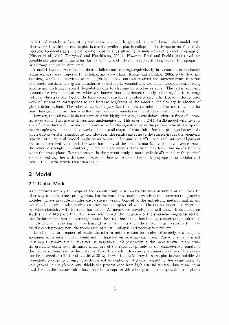
crack tip discretely in form of a priori existent voids. In general, it is well-known that models withdiscrete voids within an elastic-plastic matrix predict a plastic collapse and subsequent necking of theintervoid ligaments at su�cient level of loading thus allowing to simulate ductile crack propagation(Hütter et al., 2012; Tvergaard and Hutchinson, 2002). However, Petti and Dodds (2005) evaluatepossible cleavage only a posteriori locally by means of a Beremin-type criterion, i.e. crack propagationby cleavage cannot be simulated.A model that allows to model ductile failure and cleavage equivalently in a continuum mechanics
consistent way was proposed by Faleskog and co-workers (Kroon and Faleskog, 2005, 2008; Stec andFaleskog, 2009) and Hardenacke et al. (2012). These authors resolved the microstructure in termsof discrete particles and grain boundaries in cell model simulations, i.e. under homogeneous loadingconditions, modeling material degradation due to cleavage by a cohesive zone. The latter approachaccounts for two main features which are known from experiments: �rstly softening due to cleavageinitiates when a critical level of the local stress is reached, the cohesive strength. Secondly, the cohesivework of separation corresponds to the fracture toughness of the material for cleavage in absence ofplastic deformations. The cohesive work of separation thus forms a minimum fracture toughness forpure cleavage, a feature that is well-known from experiments (see e.g. Anderson et al., 1994).However, the cell models do not represent the highly inhomogeneous deformations in front of a crack
tip adequately. That is why the authors implemented in (Hütter et al., 2014b) a 2D model with discretevoids for the ductile failure and a cohesive zone for cleavage directly in the process zone at the tip of amacroscopic tip. This model allowed to simulate all stages of crack initiation and propagation over thewhole ductile-brittle transition region. However, the results gave rise to the suspicion that the geometricrepresentation by a 2D model might be an oversimpli�cation: in a 2D model each intervoid ligamenthas to be stretched anew until the work-hardening of the metallic matrix lets the local stresses reachthe cohesive strength. In contrast, in reality a continuous crack front may form that moves steadilyalong the crack plane. For this reason, in the present study a more realistic 3D model with sphericalvoids is used together with cohesive zone for cleavage to model the crack propagation in nodular castiron in the ductile-brittle transition region.
2 Model
2.1 Global Model
As mentioned already the scope of the present study is to resolve the microstructure at the crack tipdiscretely to model crack propagation. For the considered nodular cast iron this concerns the graphitenodules. These graphite nodules are relatively weakly bonded to the embedding metallic matrix andcan thus be modeled adequately as a priori existent spherical voids. The matrix material is describedby Mises plasticity with isotropic hardening. As mentioned already, it is well known from numerousstudies in the literature that after some void growth the reduction of the stress-carrying cross sectiondue the lateral contraction overcompensates the strain-hardening thus leading to macroscopic softening.That is why no further ingredients than a Mises-plastic matrix and discrete voids are necessary to modelductile crack propagation, the mechanism of plastic collapse and necking is su�cient.But of course in a numerical model the microstructure cannot be resolved discretely in a complete
specimen since such a model could not be handled on existing computers. Anyway, it is even notnecessary to resolve the microstructure everywhere. Only directly in the process zone at the cracktip gradients occur over distances which are of the same magnitude as the characteristic length ofthe microstructure, i.e. to the distance X0 of the voids. However, preliminary studies of the purelyductile mechanism (Hütter et al., 2012, 2013) showed that void growth in the plastic zone outside theimmediate process zone must nevertheless not be neglected. Although possibly of low magnitude, thevoid growth in the plastic zone shields the process zone from high triaxial stresses thus retarding atleast the ductile fracture initiation. In order to capture this e�ect possible void growth in the plastic
3
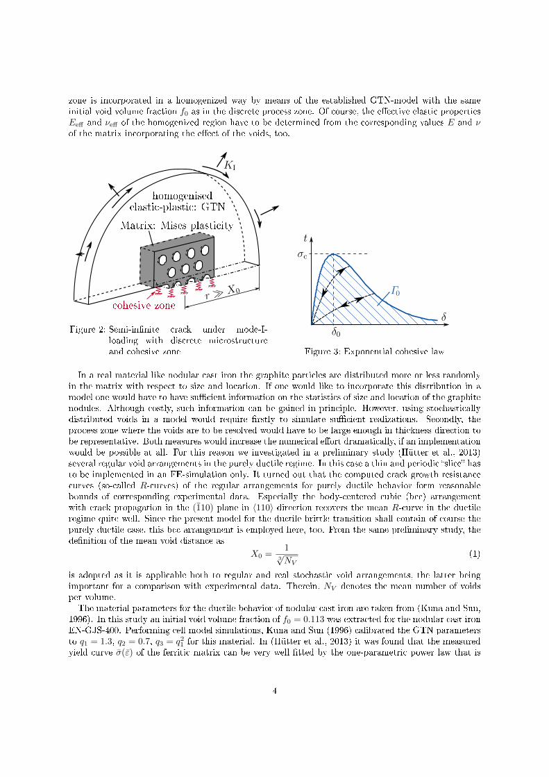
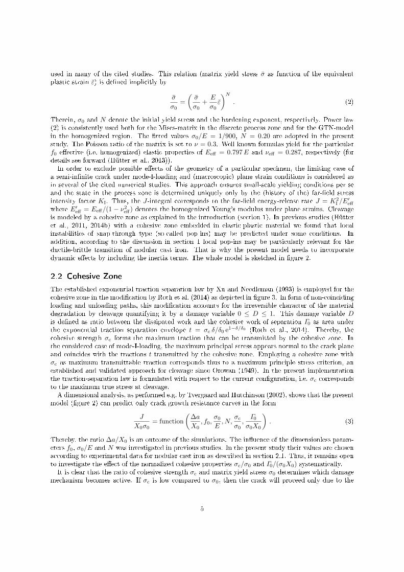
zone is incorporated in a homogenized way by means of the established GTN-model with the sameinitial void volume fraction f0 as in the discrete process zone. Of course, the e�ective elastic propertiesEeff and νeff of the homogenized region have to be determined from the corresponding values E and νof the matrix incorporating the e�ect of the voids, too.
KI
homogenised
Matrix: Mises plasti ity
r ≫ X0
ohesive zone
elasti -plasti : GTN
Figure 2: Semi-in�nite crack under mode-I-loading with discrete microstructureand cohesive zone
δ
t
σc
Γ0
δ0
Figure 3: Exponential cohesive law
In a real material like nodular cast iron the graphite particles are distributed more or less randomlyin the matrix with respect to size and location. If one would like to incorporate this distribution in amodel one would have to have su�cient information on the statistics of size and location of the graphitenodules. Although costly, such information can be gained in principle. However, using stochasticallydistributed voids in a model would require �rstly to simulate su�cient realizations. Secondly, theprocess zone where the voids are to be resolved would have to be large enough in thickness direction tobe representative. Both measures would increase the numerical e�ort dramatically, if an implementationwould be possible at all. For this reason we investigated in a preliminary study (Hütter et al., 2013)several regular void arrangements in the purely ductile regime. In this case a thin and periodic �slice� hasto be implemented in an FE-simulation only. It turned out that the computed crack growth resistancecurves (so-called R-curves) of the regular arrangements for purely ductile behavior form reasonablebounds of corresponding experimental data. Especially the body-centered cubic (bcc) arrangementwith crack propagation in the (1̄10) plane in 〈110〉 direction recovers the mean R-curve in the ductileregime quite well. Since the present model for the ductile-brittle transition shall contain of course thepurely ductile case, this bcc-arrangement is employed here, too. From the same preliminary study, thede�nition of the mean void distance as
X0 =1
3√NV
(1)
is adopted as it is applicable both to regular and real stochastic void arrangements, the latter beingimportant for a comparison with experimental data. Therein, NV denotes the mean number of voidsper volume.The material parameters for the ductile behavior of nodular cast iron are taken from (Kuna and Sun,
1996). In this study an initial void volume fraction of f0 = 0.113 was extracted for the nodular cast ironEN-GJS-400. Performing cell model simulations, Kuna and Sun (1996) calibrated the GTN parametersto q1 = 1.3, q2 = 0.7, q3 = q2
1 for this material. In (Hütter et al., 2013) it was found that the measuredyield curve σ̄(ε̄) of the ferritic matrix can be very well �tted by the one-parametric power law that is
4
used in many of the cited studies. This relation (matrix yield stress σ̄ as function of the equivalentplastic strain ε̄) is de�ned implicitly by
σ̄
σ0=
(σ̄
σ0+E
σ0ε̄
)N. (2)
Therein, σ0 and N denote the initial yield stress and the hardening exponent, respectively. Power law(2) is consistently used both for the Mises-matrix in the discrete process zone and for the GTN-modelin the homogenized region. The �tted values σ0/E = 1/900, N = 0.20 are adopted in the presentstudy. The Poisson ratio of the matrix is set to ν = 0.3. Well-known formulas yield for the particularf0 e�ective (i.e. homogenized) elastic properties of Eeff = 0.797E and νeff = 0.287, respectively (fordetails see forward (Hütter et al., 2013)).In order to exclude possible e�ects of the geometry of a particular specimen, the limiting case of
a semi-in�nite crack under mode-I-loading and (macroscopic) plane strain conditions is considered asin several of the cited numerical studies. This approach ensures small-scale yielding conditions per seand the state in the process zone is determined uniquely only by the (history of the) far-�eld stressintensity factor KI. Thus, the J-integral corresponds to the far-�eld energy-release rate J = K2
I /E′eff
where E′eff = Eeff/(1 − ν2eff) denotes the homogenized Young's modulus under plane strains. Cleavage
is modeled by a cohesive zone as explained in the introduction (section 1). In previous studies (Hütteret al., 2011, 2014b) with a cohesive zone embedded in elastic-plastic material we found that localinstabilities of snap-through type (so-called pop-ins) may be predicted under some conditions. Inaddition, according to the discussion in section 1 local pop-ins may be particularly relevant for theductile-brittle transition of nodular cast iron. That is why the present model needs to incorporatedynamic e�ects by including the inertia terms. The whole model is sketched in �gure 2.
2.2 Cohesive Zone
The established exponential traction-separation law by Xu and Needleman (1993) is employed for thecohesive zone in the modi�cation by Roth et al. (2014) as depicted in �gure 3. In form of non-coincidingloading and unloading paths, this modi�cation accounts for the irreversible character of the materialdegradation by cleavage quantifying it by a damage variable 0 ≤ D ≤ 1. This damage variable Dis de�ned as ratio between the dissipated work and the cohesive work of separation Γ0 as area underthe exponential traction separation envelope t = σc δ/δ0 e1−δ/δ0 (Roth et al., 2014). Thereby, thecohesive strength σc forms the maximum traction that can be transmitted by the cohesive zone. Inthe considered case of mode-I-loading, the maximum principal stress appears normal to the crack planeand coincides with the tractions t transmitted by the cohesive zone. Employing a cohesive zone withσc as maximum transmittable traction corresponds thus to a maximum principle stress criterion, anestablished and validated approach for cleavage since Orowan (1949). In the present implementationthe traction-separation law is formulated with respect to the current con�guration, i.e. σc correspondsto the maximum true stress at cleavage.A dimensional analysis, as performed e.g. by Tvergaard and Hutchinson (2002), shows that the present
model (�gure 2) can predict only crack growth resistance curves in the form
J
X0σ0= function
(∆a
X0, f0,
σ0
E,N,
σc
σ0,Γ0
σ0X0
). (3)
Thereby, the ratio ∆a/X0 is an outcome of the simulations. The in�uence of the dimensionless param-eters f0, σ0/E and N was investigated in previous studies. In the present study their values are chosenaccording to experimental data for nodular cast iron as described in section 2.1. Thus, it remains opento investigate the e�ect of the normalized cohesive properties σc/σ0 and Γ0/(σ0X0) systematically.It is clear that the ratio of cohesive strength σc and matrix yield stress σ0 determines which damage
mechanism becomes active. If σc is low compared to σ0, then the crack will proceed only due to the
5
softening in the cohesive zone without any plastic deformations and thus without any void growth,i.e. only by cleavage. In contrast, if σc is considerably larger than σ0, strong plastic deformations arerequired until the work-hardening drives the local stress level to σc corresponding thus to the ductileregime. In this context it has to be remarked that with the present model �nal failure of an intervoidligament will appear always in the cohesive zone due to the employed non-saturating hardening law(2). Thus, in the simulations single values of the damage D in the cohesive zone cannot be relatedto ductility. Rather, such information can only be gained from extracted R-curves which contain theplastic contribution to the dissipation during crack growth.Regarding the temperature dependence of the quantities σc and σ0, it can �rstly be stated that nodular
cast iron exhibits an increasing yield stress σ0 with decreasing temperature as typical engineering metalsdo. In contrast, it was found already in the beginning of the 1970s (Gri�ths and Owen, 1971; Knott,1973) that the cleavage fracture stress of mild steels is practically constant over a very wide temperaturerange. The matrix of mild steels is similar to the considered nodular cast iron so that the cohesivestrength σc can be assumed to be constant. Thus, the ratio σc/σ0 increases with the temperature andthe transition to brittle failure with decreasing temperature is mainly driven by the increasing yieldstress. In the following simulations the ratio σc/σ0 is varied systematically to investigate the in�uenceof temperature.The cohesive work of separation Γ0 represents the lower-bound fracture toughness for pure cleav-
age as already discussed. However, the practical determination of this value requires considerableexperimental e�ort. An extensive experimental investigation of the fracture toughness of nodular castiron in the ductile-brittle transition region for temperatures down to −140 ◦C was performed by Motzet al. (1980). They found no fracture toughness values (in terms of the stress intensity factor) belowKc ≈ 1000MPa mm1/2. This lower-bound fracture toughness corresponds to a work of separation ofabout Γ0 = 5N/mm. Eq. (3) shows that for the present model the normalized work of separationΓ0/(σ0X0) is important. For the ferritic nodular cast iron to be considered later for a comparison withexperimental data realistic values of the distance of voids and of the yield stress are X0 =30 µm to130 µm and σ0 =250MPa to 300MPa, respectively. Thus, the normalized work of separation lies in therange 0.1 < Γ0/(σ0X0) < 0.6. Out of this range we consider arbitrarily the values Γ0/(σ0X0) = 0.125and Γ0/(σ0X0) = 0.250 for the following simulations. Focusing on the temperature dependence byvarying the ratio σc/σ0, the results in section 3 will refer to Γ0/(σ0X0) = 0.125 if not stated otherwise.
2.3 Numerical Implementation
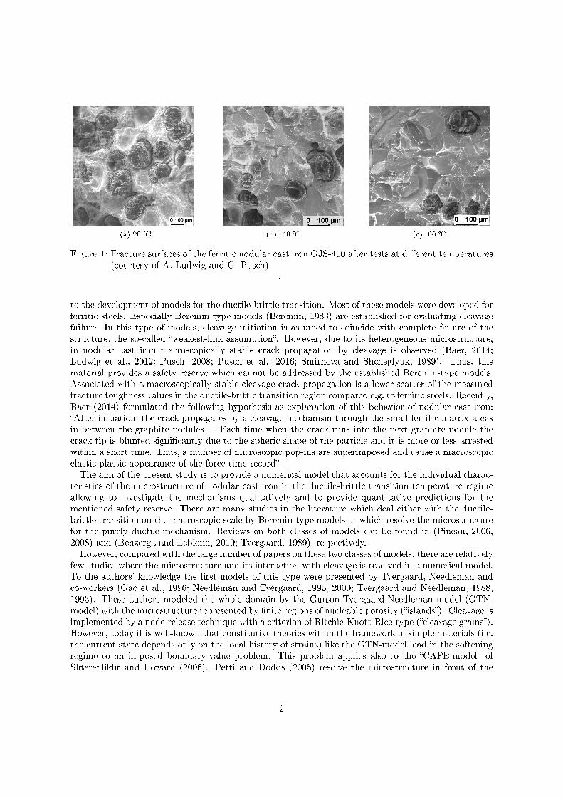
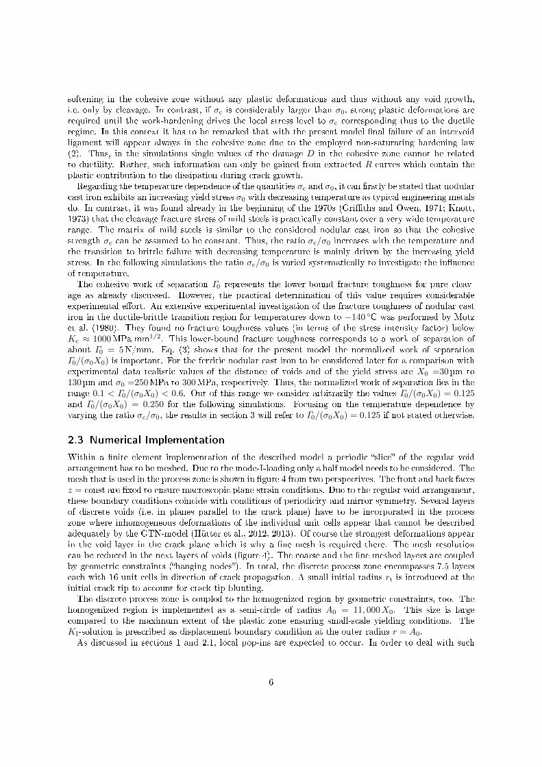
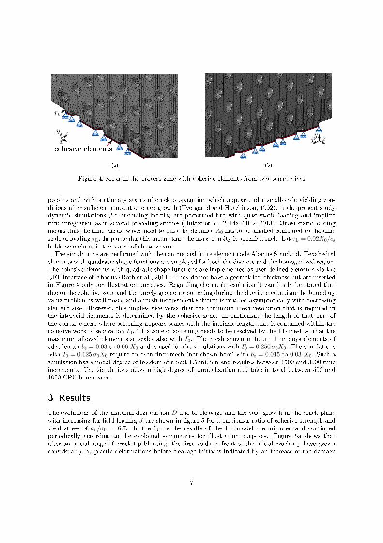
Within a �nite element implementation of the described model a periodic �slice� of the regular voidarrangement has to be meshed. Due to the mode-I-loading only a half model needs to be considered. Themesh that is used in the process zone is shown in �gure 4 from two perspectives. The front and back facesz = const are �xed to ensure macroscopic plane strain conditions. Due to the regular void arrangement,these boundary conditions coincide with conditions of periodicity and mirror symmetry. Several layersof discrete voids (i.e. in planes parallel to the crack plane) have to be incorporated in the processzone where inhomogeneous deformations of the individual unit cells appear that cannot be describedadequately by the GTN-model (Hütter et al., 2012, 2013). Of course the strongest deformations appearin the void layer in the crack plane which is why a �ne mesh is required there. The mesh resolutioncan be reduced in the next layers of voids (�gure 4). The coarse and the �ne meshed layers are coupledby geometric constraints (�hanging nodes�). In total, the discrete process zone encompasses 7.5 layerseach with 16 unit cells in direction of crack propagation. A small initial radius rt is introduced at theinitial crack tip to account for crack tip blunting.The discrete process zone is coupled to the homogenized region by geometric constraints, too. The
homogenized region is implemented as a semi-circle of radius A0 = 11, 000X0. This size is largecompared to the maximum extent of the plastic zone ensuring small-scale yielding conditions. TheKI-solution is prescribed as displacement boundary condition at the outer radius r = A0.As discussed in sections 1 and 2.1, local pop-ins are expected to occur. In order to deal with such
6
ohesive elements
x
y z
rt
(a)
xy
z
(b)
Figure 4: Mesh in the process zone with cohesive elements from two perspectives
pop-ins and with stationary states of crack propagation which appear under small-scale yielding con-ditions after su�cient amount of crack growth (Tvergaard and Hutchinson, 1992), in the present studydynamic simulations (i.e. including inertia) are performed but with quasi-static loading and implicittime integration as in several preceding studies (Hütter et al., 2014a, 2012, 2013). Quasi-static loadingmeans that the time elastic waves need to pass the distance A0 has to be smalled compared to the timescale of loading τL. In particular this means that the mass density is speci�ed such that τL = 0.02X0/csholds wherein cs is the speed of shear waves.The simulations are performed with the commercial �nite element code Abaqus Standard. Hexahedral
elements with quadratic shape functions are employed for both the discrete and the homogenized region.The cohesive elements with quadratic shape functions are implemented as user-de�ned elements via theUEL interface of Abaqus (Roth et al., 2014). They do not have a geometrical thickness but are insertedin Figure 4 only for illustration purposes. Regarding the mesh resolution it can �rstly be stated thatdue to the cohesive zone and the purely geometric softening during the ductile mechanism the boundaryvalue problem is well-posed and a mesh-independent solution is reached asymptotically with decreasingelement size. However, this implies vice versa that the minimum mesh resolution that is required inthe intervoid ligaments is determined by the cohesive zone. In particular, the length of that part ofthe cohesive zone where softening appears scales with the intrinsic length that is contained within thecohesive work of separation Γ0. This zone of softening needs to be resolved by the FE mesh so that themaximum allowed element size scales also with Γ0. The mesh shown in �gure 4 employs elements ofedge length be = 0.03 to 0.06 X0 and is used for the simulations with Γ0 = 0.250σ0X0. The simulationswith Γ0 = 0.125σ0X0 require an even �ner mesh (not shown here) with be = 0.015 to 0.03 X0. Such asimulation has a nodal degree of freedom of about 1.5 million and requires between 1500 and 3000 timeincrements. The simulations allow a high degree of parallelization and take in total between 500 and1000 CPU hours each.
3 Results
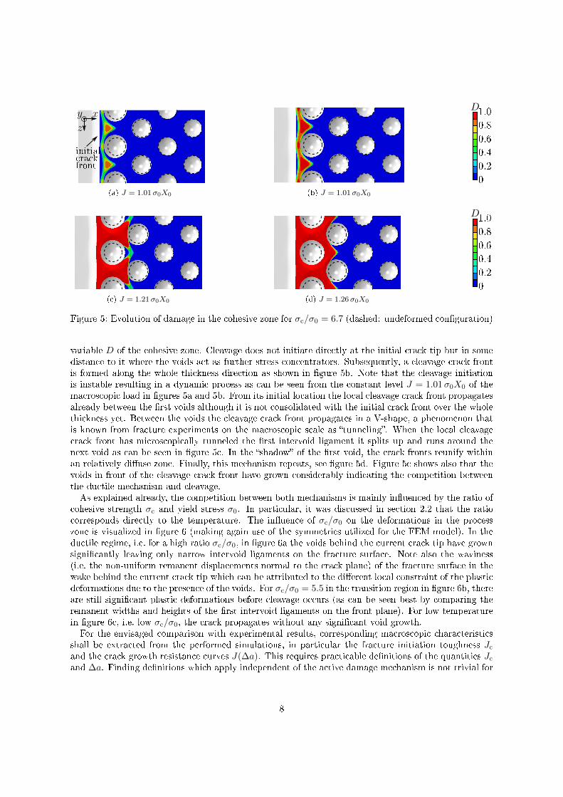
The evolutions of the material degradation D due to cleavage and the void growth in the crack planewith increasing far-�eld loading J are shown in �gure 5 for a particular ratio of cohesive strength andyield stress of σc/σ0 = 6.7. In the �gure the results of the FE model are mirrored and continuedperiodically according to the exploited symmetries for illustration purposes. Figure 5a shows thatafter an initial stage of crack tip blunting, the �rst voids in front of the initial crack tip have grownconsiderably by plastic deformations before cleavage initiates indicated by an increase of the damage
7
initial
ra k
front
x
z
y
(a) J = 1.01σ0X0 (b) J = 1.01σ0X0
0
0.2
0.4
0.6
0.8
1.0
D
(c) J = 1.21σ0X0 (d) J = 1.26σ0X0
0
0.2
0.4
0.6
0.8
1.0
D
Figure 5: Evolution of damage in the cohesive zone for σc/σ0 = 6.7 (dashed: undeformed con�guration)
variable D of the cohesive zone. Cleavage does not initiate directly at the initial crack tip but in somedistance to it where the voids act as further stress concentrators. Subsequently, a cleavage crack frontis formed along the whole thickness direction as shown in �gure 5b. Note that the cleavage initiationis instable resulting in a dynamic process as can be seen from the constant level J = 1.01σ0X0 of themacroscopic load in �gures 5a and 5b. From its initial location the local cleavage crack front propagatesalready between the �rst voids although it is not consolidated with the initial crack front over the wholethickness yet. Between the voids the cleavage crack front propagates in a V-shape, a phenomenon thatis known from fracture experiments on the macroscopic scale as �tunneling�. When the local cleavagecrack front has microscopically tunneled the �rst intervoid ligament it splits up and runs around thenext void as can be seen in �gure 5c. In the �shadow� of the �rst void, the crack fronts reunify withinan relatively di�use zone. Finally, this mechanism repeats, see �gure 5d. Figure 5c shows also that thevoids in front of the cleavage crack front have grown considerably indicating the competition betweenthe ductile mechanism and cleavage.As explained already, the competition between both mechanisms is mainly in�uenced by the ratio of
cohesive strength σc and yield stress σ0. In particular, it was discussed in section 2.2 that the ratiocorresponds directly to the temperature. The in�uence of σc/σ0 on the deformations in the processzone is visualized in �gure 6 (making again use of the symmetries utilized for the FEM model). In theductile regime, i.e. for a high ratio σc/σ0, in �gure 6a the voids behind the current crack tip have grownsigni�cantly leaving only narrow intervoid ligaments on the fracture surface. Note also the waviness(i.e. the non-uniform remanent displacements normal to the crack plane) of the fracture surface in thewake behind the current crack tip which can be attributed to the di�erent local constraint of the plasticdeformations due to the presence of the voids. For σc/σ0 = 5.5 in the transition region in �gure 6b, thereare still signi�cant plastic deformations before cleavage occurs (as can be seen best by comparing theremanent widths and heights of the �rst intervoid ligaments on the front plane). For low temperaturein �gure 6c, i.e. low σc/σ0, the crack propagates without any signi�cant void growth.For the envisaged comparison with experimental results, corresponding macroscopic characteristics
shall be extracted from the performed simulations, in particular the fracture initiation toughness Jc
and the crack growth resistance curves J(∆a). This requires practicable de�nitions of the quantities Jc
and ∆a. Finding de�nitions which apply independent of the active damage mechanism is not trivial for
8
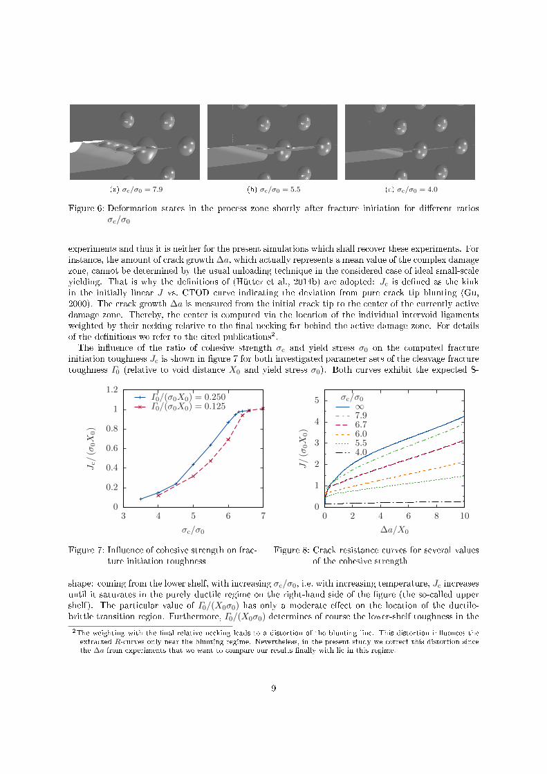
(a) σc/σ0 = 7.9 (b) σc/σ0 = 5.5 (c) σc/σ0 = 4.0
Figure 6: Deformation states in the process zone shortly after fracture initiation for di�erent ratiosσc/σ0
experiments and thus it is neither for the present simulations which shall recover these experiments. Forinstance, the amount of crack growth ∆a, which actually represents a mean value of the complex damagezone, cannot be determined by the usual unloading technique in the considered case of ideal small-scaleyielding. That is why the de�nitions of (Hütter et al., 2014b) are adopted: Jc is de�ned as the kinkin the initially linear J vs. CTOD curve indicating the deviation from pure crack tip blunting (Gu,2000). The crack growth ∆a is measured from the initial crack tip to the center of the currently activedamage zone. Thereby, the center is computed via the location of the individual intervoid ligamentsweighted by their necking relative to the �nal necking far behind the active damage zone. For detailsof the de�nitions we refer to the cited publications2.The in�uence of the ratio of cohesive strength σc and yield stress σ0 on the computed fracture
initiation toughness Jc is shown in �gure 7 for both investigated parameter sets of the cleavage fracturetoughness Γ0 (relative to void distance X0 and yield stress σ0). Both curves exhibit the expected S-
0
0.2
0.4
0.6
0.8
1
1.2
3 4 5 6 7
Jc/(σ
0X
0)
σc/σ0
Γ0/(σ0X0) = 0.250Γ0/(σ0X0) = 0.125
Figure 7: In�uence of cohesive strength on frac-ture initiation toughness
0
1
2
3
4
5
0 2 4 6 8 10
J/(σ
0X
0)
∆a/X0
σc/σ0∞7.96.76.05.54.0
Figure 8: Crack resistance curves for several valuesof the cohesive strength
shape: coming from the lower shelf, with increasing σc/σ0, i.e. with increasing temperature, Jc increasesuntil it saturates in the purely ductile regime on the right-hand side of the �gure (the so-called uppershelf). The particular value of Γ0/(X0σ0) has only a moderate e�ect on the location of the ductile-brittle transition region. Furthermore, Γ0/(X0σ0) determines of course the lower-shelf toughness in the
2The weighting with the �nal relative necking leads to a distortion of the blunting line. This distortion in�uences theextracted R-curves only near the blunting regime. Nevertheless, in the present study we correct this distortion sincethe ∆a from experiments that we want to compare our results �nally with lie in this regime.
9
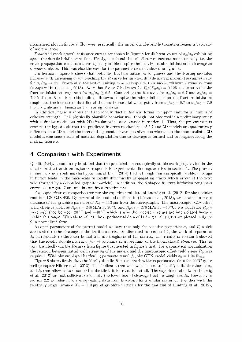
normalized plot in �gure 7. However, practically the upper ductile-brittle transition region is typicallyof more interest.Extracted crack growth resistance curves are shown in �gure 8 for di�erent values of σc/σ0 exhibiting
again the ductile-brittle transition. Firstly, it is found that all R-curves increase monotonically, i.e. thecrack propagation remains macroscopically stable despite the locally instable initiation of cleavage asdiscussed above. This was also the case for the parameter sets not shown in �gure 8.Furthermore, �gure 8 shows that both the fracture initiation toughness and the tearing modulus
increase with increasing σc/σ0 reaching the R-curve for an ideal ductile matrix material asymptoticallyfor σc/σ0 → ∞. Practically, the latter limiting case corresponds to a model without a cohesive zone(compare Hütter et al., 2013). Note that �gure 7 indicates for Γ0/(X0σ0) = 0.125 a saturation in thefracture initiation toughness for σc/σ0 & 6.5. Comparing the R-curves for σc/σ0 = 6.7 and σc/σ0 =7.9 in �gure 8 con�rms this �nding. However, despite the minor in�uence on the fracture initiationtoughness, the increase of ductility of the matrix material when going from σc/σ0 = 6.7 to σc/σ0 = 7.9has a signi�cant in�uence on the tearing behavior.In addition, �gure 8 shows that the ideally ductile R-curve forms an upper limit for all values of
cohesive strength. This physically plausible behavior was, though, not observed in a preliminary studywith a similar model but with 2D circular voids as discussed in section 1. Thus, the present resultscon�rm the hypothesis that the predicted fracture mechanisms of 2D and 3D models are qualitativelydi�erent: In a 2D model the intervoid ligaments cleave one after one whereas in the more realistic 3Dmodel a continuous zone of material degradation due to cleavage is formed and propagates along thematrix, �gure 5.
4 Comparison with Experiments
Qualitatively, it can �rstly be stated that the predicted macroscopically stable crack propagation in theductile-brittle transition region corresponds to experimental �ndings as cited in section 1. The presentnumerical study con�rms the hypothesis of Baer (2014) that although macroscopically stable, cleavageinitiation leads on the microscale to locally dynamically propagating cracks which arrest at the nextvoid (formed by a debonded graphite particle). In addition, the S-shaped fracture initiation toughnesscurves as in �gure 7 are well known from experiments.For a quantitative comparison we use the experimental data of Ludwig et al. (2012) for the nodular
cast iron EN-GJS-400. By means of the method outlined in (Hütter et al., 2013), we obtained a meandistance of the graphite particles of X0 = 113 µm from the micrographs. The macroscopic 0.2% o�setyield stress is given as Rp0.2 = 246MPa at 20 ◦C and Rp0.2 = 276MPa at −40 ◦C. No values for Rp0.2
were published between 20 ◦C and −40 ◦C which is why the necessary values are interpolated linearlywithin this range. With these values, the experimental data of Ludwig et al. (2012) are plotted in �gure9 in normalized form.As open parameters of the present model we have thus only the cohesive properties σc and Γ0 which
are related to the cleavage of the ferritic matrix. As discussed in section 2.2, the work of separationΓ0 corresponds to the lower-bound fracture toughness of the matrix. The results in section 3 showedthat the ideally ductile matrix σc/σ0 →∞ forms an upper limit of the (normalized) R-curves. That iswhy the ideally ductile R-curve from �gure 8 is inserted in �gure 9 �rst. For a consistent normalizationthe relation between initial yield stress σ0 of the matrix and the macroscopic o�set yield stress Rp0.2 isrequired. With the employed hardening parameters and f0, the GTN model yields σ0 = 1.04Rp0.2.Figure 9 shows �rstly that the ideally ductile R-curve matches the experimental data for 20 ◦C quite
well (compare Hütter et al., 2013). This indicates that we have a chance to identify suitable values of σc
and Γ0 that allow us to describe the ductile-brittle transition at all. The experimental data in (Ludwiget al., 2012) are not su�cient to identify the lower bound cleavage fracture toughness Γ0. However, insection 2.2 we referenced corresponding data from literature for a similar material. Together with therelatively large distance X0 = 113µm of graphite particles for the material of (Ludwig et al., 2012),
10
0
1
2
3
4
0 1 2 3 4 5 6
J/(R
p0.2X
0)
∆a/X0
Experiments20°C
0°C-20°C-40°CSimulationsσc/σ0 = ∞σc/σ0 = 7.6σc/σ0 = 7.0σc/σ0 = 6.4
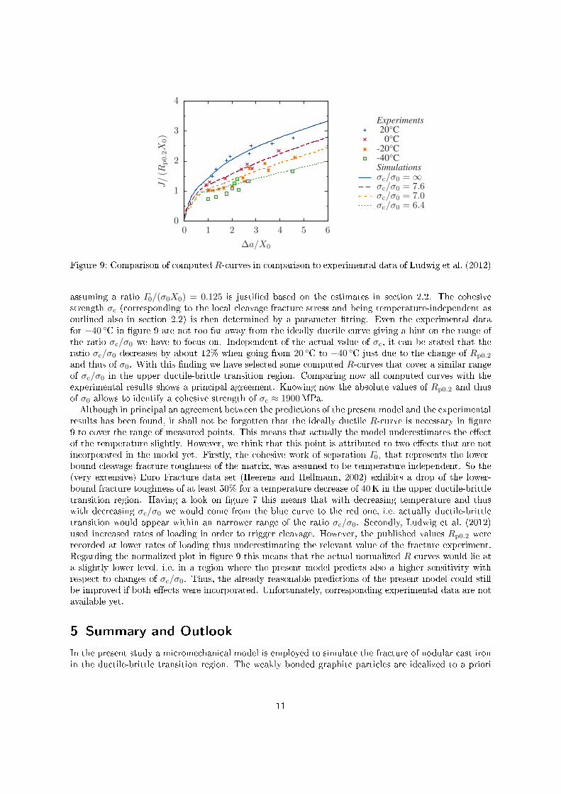
Figure 9: Comparison of computed R-curves in comparison to experimental data of Ludwig et al. (2012)
assuming a ratio Γ0/(σ0X0) = 0.125 is justi�ed based on the estimates in section 2.2. The cohesivestrength σc (corresponding to the local cleavage fracture stress and being temperature-independent asoutlined also in section 2.2) is then determined by a parameter �tting. Even the experimental datafor −40 ◦C in �gure 9 are not too far away from the ideally ductile curve giving a hint on the range ofthe ratio σc/σ0 we have to focus on. Independent of the actual value of σc, it can be stated that theratio σc/σ0 decreases by about 12% when going from 20 ◦C to −40 ◦C just due to the change of Rp0.2
and thus of σ0. With this �nding we have selected some computed R-curves that cover a similar rangeof σc/σ0 in the upper ductile-brittle transition region. Comparing now all computed curves with theexperimental results shows a principal agreement. Knowing now the absolute values of Rp0.2 and thusof σ0 allows to identify a cohesive strength of σc ≈ 1900MPa.Although in principal an agreement between the predictions of the present model and the experimental
results has been found, it shall not be forgotten that the ideally ductile R-curve is necessary in �gure9 to cover the range of measured points. This means that actually the model underestimates the e�ectof the temperature slightly. However, we think that this point is attributed to two e�ects that are notincorporated in the model yet. Firstly, the cohesive work of separation Γ0, that represents the lower-bound cleavage fracture toughness of the matrix, was assumed to be temperature independent. So the(very extensive) Euro Fracture data set (Heerens and Hellmann, 2002) exhibits a drop of the lower-bound fracture toughness of at least 50% for a temperature decrease of 40K in the upper ductile-brittletransition region. Having a look on �gure 7 this means that with decreasing temperature and thuswith decreasing σc/σ0 we would come from the blue curve to the red one, i.e. actually ductile-brittletransition would appear within an narrower range of the ratio σc/σ0. Secondly, Ludwig et al. (2012)used increased rates of loading in order to trigger cleavage. However, the published values Rp0.2 wererecorded at lower rates of loading thus underestimating the relevant value of the fracture experiment.Regarding the normalized plot in �gure 9 this means that the actual normalized R-curves would lie ata slightly lower level, i.e. in a region where the present model predicts also a higher sensitivity withrespect to changes of σc/σ0. Thus, the already reasonable predictions of the present model could stillbe improved if both e�ects were incorporated. Unfortunately, corresponding experimental data are notavailable yet.
5 Summary and Outlook
In the present study a micromechanical model is employed to simulate the fracture of nodular cast ironin the ductile-brittle transition region. The weakly bonded graphite particles are idealized to a priori
11
existing spherical voids that are resolved discretely in the process zone at the crack tip. Possible voidgrowth around the process zone is incorporated in a homogenized way by means of the GTN-model.Cleavage is modeled by a cohesive zone capturing both the local fracture stress for cleavage by thecohesive strength and the energy required to drive the cleavage by the cohesive work of separation.Investigating a regular void arrangement, it is su�cient to mesh a periodic slice of the con�guration inthe �nite element implementation thus keeping the numerical e�ort at a handleable level. A parameterstudy is performed with respect to the cohesive parameters. The results showed that the present modelcaptures qualitatively the behavior of nodular cast iron: the typical S-shape in the fracture initiationtoughness plotted versus the temperature with a well-de�ned lower-shelf toughness and the stable crackpropagation by cleavage in the ductile-brittle transition region. A comparison with experimental datafrom literature demonstrated that the proposed model allows in principle also quantitative predictionsof the fracture initiation and propagation in nodular cast iron. Remarkably, the results of the presentstudy di�er qualitatively from those of a preliminary study with a similar but two-dimensional model.Thus, it has to be concluded that the computationally more expensive three-dimensional models arenecessary for simulating the ductile-brittle transition adequately on the microscopic level. Presumably,this conclusion holds also if the ductile failure competes with other damage mechanisms like growth ofsecondary voids.In the present model the plastic behavior of the metallic matrix material was assumed to be rate-
independent in order to keep the number of model parameters as small as possible. However, in practicethe ductile-brittle transition under dynamic loading is a very important topic. So the next step wouldbe to extend the present model towards rate-dependent behavior. Under dynamic loading conditions,the competition between strain-rate hardening and adiabatic softening in the intervoid ligaments willbecome an interesting aspect. It will also be interesting to apply the present model to other materialslike steel. In steels the fracture initiation by cleavage is, in contrast to nodular cast iron, typicallyunstable. Compared to nodular cast iron the void nucleating particles in steels have a lower volumefraction and are harder than the graphite. So it remains open to investigate the roles of the volumefraction of particles as well as of their bulk and bonding properties on the ductile-brittle transition.
Acknowledgments
The present study was funded by the Deutsche Forschungsgemeinschaft (DFG, German Research Foun-dation) under contract KU 929/14. Furthermore, the �nancial support by the DFG for the computingfacilities under contract INST 267/81 FUGG is gratefully acknowledged. The authors thank StephanRoth for providing his cohesive zone implementation for the Abaqus interface UEL and the studentRostyslav Skrypnyk for preparing �nite element meshes.
References
Anderson, T., Stienstra, D., Dodds Jr, R., 1994. A theoretical framework for addressing fracture inthe ductile-brittle transition region, in: Fracture mechanics: twenty-fourth volume. number 1207 inASTM STP, pp. 186�214.
Baer, W., 2014. Performance of modern DCI materials � investigation of microstructural, temperatureand loading rate e�ects on mechanical and fracture mechanical properties. Mater. Sci. Forum. 783,2244�2249.
Benzerga, A.A., Leblond, J.B., 2010. Ductile fracture by void growth to coalescence. Adv. Appl. Mech.Volume 44, 169�305.
Beremin, F.M., 1983. A local criterion for cleavage fracture of a nuclear pressure vessel steel. Metall.Mater. Trans. A. 14A, 2277�2287.
12
Gao, X., Shih, C.F., Tvergaard, V., Needleman, A., 1996. Constraint e�ects on the ductile-brittletransition in small scale yielding. J. Mech. Phys. Solids. 44, 1255�1282.
Gri�ths, J., Owen, D., 1971. An elastic-plastic stress analysis for a notched bar in plane strain bending.J. Mech. Phys. Solids. 19, 419�431.
Gu, I., 2000. Finite element analyses of deformation around holes near a crack tip and their implicationsto the J-resistance curve. Fatigue. Fract. Eng. M. 23, 943�952.
Hardenacke, V., Hohe, J., Friedmann, V., Siegele, D., 2012. Enhancement of local approach modelsfor assessment of cleavage fracture considering micromechanical aspects, in: Proceedings of the 19th
European Conference on Fracture.
Heerens, J., Hellmann, D., 2002. Development of the euro fracture toughness dataset. Eng. Fract. Mech.69, 421�449.
Hütter, G., Linse, T., Roth, S., Mühlich, U., Kuna, M., 2014a. A modeling approach for the completeductile-brittle transition region: Cohesive zone in combination with a non-local Gurson-model. Int.J. Fracture. 185, 129�153.
Hütter, G., Mühlich, U., Kuna, M., 2011. Simulation of local instabilities during crack propagation inthe ductile-brittle transition region. Eur. J. Mech. A-Solid. 30, 195�203.
Hütter, G., Zybell, L., Kuna, M., 2014b. Micromechanical modeling of crack propagation with compet-ing ductile and cleavage failure. Procedia Mater. Sci. 3, 428�433.
Hütter, G., Zybell, L., Mühlich, U., Kuna, M., 2012. Ductile crack propagation by plastic collapse ofthe intervoid ligaments. Int. J. Fracture. 176, 81�96.
Hütter, G., Zybell, L., Mühlich, U., Kuna, M., 2013. Consistent simulation of ductile crack propagationwith discrete 3D voids. Comp. Mater. Sci. 80, 61�70.
Knott, J.F., 1973. Fundamentals of Fracture Mechanics. Butterworths, London � Boston.
Kroon, M., Faleskog, J., 2005. Micromechanics of cleavage fracture initiation in ferritic steels by carbidecracking. J. Mech. Phys. Solids. 53, 171�196.
Kroon, M., Faleskog, J., 2008. In�uence of crack de�ection into the carbide/ferrite interface on cleavagefracture initiation in ferritic steels. Mech. Mater. 40, 695�707.
Kuna, M., Sun, D.Z., 1996. Three-dimensional cell model analyses of void growth in ductile materials.Int. J. Fracture. 81, 235�258.
Ludwig, A., Pusch, G., Trubitz, P., Winkler, H.P., Hüggenberg, R., 2012. Ermittlung und De�nitiondynamischer Bruchzähigkeitswerte für ferritische Gusseisenwerksto�e. Giesserei-Praxis 63, 10�13.
Motz, J.M., Berger, D., Cohrt, G., Godehardt, E.K., Hüttebräucker, K., Kuhn, G., Reuter, H.,Schock, D., und D. Walters, W.S., 1980. Bruchmechanische Eigenschaften in groÿen Wanddickenvon Guÿstücken aus Guÿeisen mit Kugelgraphit. Giesserei-Forschung 32, 97�111.
Needleman, A., Tvergaard, V., 1995. Analysis of a brittle-ductile transition under dynamic shearloading. Int. J. Solids. Struct. 32, 2571�2590.
Needleman, A., Tvergaard, V., 2000. Numerical modeling of the ductile-brittle transition. Int. J.Fracture. 101, 73�97.
Orowan, E., 1949. Fracture and strength of solids. Rep. Prog. Phys. 12, 185�232.
13
Petti, J.P., Dodds, Jr., R.H., 2005. Ductile tearing and discrete void e�ects on cleavage fracture undersmall-scale yielding conditions. Int. J. Solids. Struct. 42, 3655�3676.
Pineau, A., 2006. Development of the local approach to fracture over the past 25 years: Theory andapplication. Int. J. Fracture. 138, 139�166.
Pineau, A., 2008. Modeling ductile to brittle fracture transition in steels � micromechanical andphysical challenges. Int. J. Fracture. 150, 129�156.
Pusch, G., 2008. Bruchmechanische Kennwerte von Gusseisenwerksto�en. Konstruieren + Giessen 33,2�34.
Pusch, G., Henkel, S., Biermann, H., Hübner, P., Ludwig, A., Trubitz, P., Mottitschka, T., Krüger,L., 2016. Determination of fracture mechanics parameters for cast iron materials under static, dy-namic and cyclic loading, in: Hütter, G., Zybell, L. (Eds.), Recent Trends in Fracture and DamageMechanics. Springer, pp. 159�196.
Roth, S., Hütter, G., Kuna, M., 2014. Simulation of fatigue crack growth with a cyclic cohesive zonemodel. Int. J. Fracture. 188, 23�45.
Shterenlikht, A., Howard, I.C., 2006. The CAFE model of fracture�application to a TMCR steel.Fatigue. Fract. Eng. M. 29, 770�787.
Smirnova, L.N., Shcheglyuk, N.I., 1989. Features of failure for ferritic cast iron with spheroidal graphite.Met. Sci. Heat. Treat. 31, 255�258.
Stec, M., Faleskog, J., 2009. In�uence of grain size on arrest of a dynamically propagating cleavagecrack in ferritic steels�micromechanics. Int. J. Fracture. 158, 51�71.
Tvergaard, V., 1989. Material failure by void growth to coalescence. Adv. Appl. Mech. 27, 83�151.
Tvergaard, V., Hutchinson, J.W., 1992. The relation between crack growth resistance and fractureprocess parameters in elastic-plastic solids. J. Mech. Phys. Solids. 40, 1377�1397.
Tvergaard, V., Hutchinson, J.W., 2002. Two mechanisms of ductile fracture: void by void growth versusmultiple void interaction. Int. J. Solids. Struct. 39, 3581�3597.
Tvergaard, V., Needleman, A., 1988. An analysis of the temperature and rate dependence of CharpyV-notch energies for a high nitrogen steel. Int. J. Fracture. 37, 197�215.
Tvergaard, V., Needleman, A., 1993. An analysis of the brittle-ductile transition in dynamic crackgrowth. Int. J. Fracture. 59, 53�67.
Xu, X.P., Needleman, A., 1993. Void nucleation by inclusion debonding in a crystal matrix. Model.Simul. Mater. Sc. 1, 111�132.
14