MICROMASTER 4, LC filter Sizes A to C - Siemens AG · MICROMASTER 4, LC Filter Sizes D to F...
6
© Siemens AG 2009 A5E00894743A 3 Issue 04/09 MICROMASTER 4, LC filter Sizes A to C Description This LC filter limits the voltage gradient and the capacitive re-charging currents which generally occur in inverter operation. This is the reason that when an LC filter is used, significantly longer screened motor feeder cables are possible and the motor lifetime reaches the same values which are achieved when the motor is connected directly on-line. CAUTION Correct installation is essential for safe operation. NOTES The LC filter, Sizes A to C, are designed as sub-chassis filters. These filters can be used for all MICROMASTER 4 drive inverters, Sizes A to C. Sizes A and B: A maximum of two sub-chassis components plus drive inverter are permissible. In this case, the LC filter must be mounted/installed as the lowest component. Size C: Only one sub-chassis component is permissible for Size C. If the line reactor and LC filter are used, then the line reactor must be installed left to the drive inverter. The following clearance is required: 7.5 cm. The following must be observed when using LC filters: Only V/f, FCC control is permissible. Use filter only under load ! Operation is only permissible with a pulse frequency of 4 kHz. Make shure that the automatic pulse frequency reductions are disabled. Coercing required parameter adjusting: P1800 = 4 kHz, P0290 = 0 or 1 CAUTION Operation with a pulse frequency of 2 kHz leads to overheating the LC Filter. If the motor data identification (Mot-ID) run is not properly completed (F0041) during commissioning the drive inverter, the LC filter must be disconnected from the motor circuit and the Mot-ID run repeated. The output frequency is limited to a maximum of 150 Hz (restrictions see Table 1). CAUTION Size A When operating with LC filter 6SE6400-3TD00-4AD0 the following output frequencies must not be exceeded: Table 1 Reduction of output frequency Rated output Output frequency Rated output Output frequency 0,37 kW, 380 … 480 V 90 Hz 0,75 kW, 380 … 480 V 110 Hz 0,55 kW, 380 … 480 V 100 Hz 1,1 kW, 380 … 480 V 130 Hz Technical data Table 2 Selection data Current [A] Order No. LC filter Size Voltage [V] 40 °C 50 °C 6SE6400-3TD00-4AD0 A 380 – 480 4.5 4.1 6SE6400-3TD01-0BD0 B 380 – 480 11.2 10.2 6SE6400-3TD03-2CD0 C 380 – 480 32.6 26.0 6SE6400-3TD01-0CE0 C ( 1 ) 500 – 600 9.0 6.1 6SE6400-3TD02-3CE0 C ( 2 ) 500 – 600 22.4 17 ( 1 ) = Use with inverter 0.75 kW up to 4.0 kW ( 2 ) = Use with inverter 5.0 kW up to 11 kW Fig. 1 LC filter, Size C Table 3 General electrical data Rated filter current See Table 2 Motor overvoltage limiting ≤ 1078 V dv/dt limiting ≤ 500 V/μs Pulse frequency 4 kHz Max. motor frequency 150 Hz Hz (restrictions see Table 1) Max. permissible motor feeder cable lengths Shielded 200 m Unshielded 300 m Insulation strength Overvoltage Category III acc. to VDE 0110 Electromagnetic compatibility Up to 200 m motor cables length with emission levels ( Conducted Emission ) acc. to Class A, acc. to EN 55011 in conjunction with filtered drive inverters and non-shielded feeder cables Table 4 General technical data Conformance CE according to the Low-Voltage Directive 73/23/EC Certification cUL E 219022 Mechanical strength EN 60068-2-31 Air humidity 95% air humidity, no moisture condensation Degree of protection IP20 (according EN60529) Insulation Class H (180 °C) Permissible temperature Storage: - 25 °C to + 70 °C Operation: - 10 °C to + 40 °C 100 % P rated to + 50 °C 80 % P rated Permissible installation altitude To 2000 m: 100 % P rated 2000 to 4000 m 62.5 % P rated Mounting position Vertical Installation clearance Top: 100 mm Bottom: 100 mm Side: 100 mm Connection system Input, finely-stranded: 1U1, 1V1, 1W1 Output, terminals: 1U2, 1V2, 1W2 Torque for power connections 1.5 Nm to 1.8 Nm
Transcript of MICROMASTER 4, LC filter Sizes A to C - Siemens AG · MICROMASTER 4, LC Filter Sizes D to F...

© Siemens AG 2009 A5E00894743A 3 Issue 04/09
MICROMASTER 4, LC filter Sizes A to C Description This LC filter limits the voltage gradient and the capacitive re-charging currents which generally occur in inverter operation. This is the reason that when an LC filter is used, significantly longer screened motor feeder cables are possible and the motor lifetime reaches the same values which are achieved when the motor is connected directly on-line.
CAUTION Correct installation is essential for safe operation.
NOTES The LC filter, Sizes A to C, are designed as sub-chassis filters. These filters can be used for all MICROMASTER 4 drive inverters, Sizes A to C. Sizes A and B: A maximum of two sub-chassis components plus drive inverter are permissible. In this case, the LC filter must be mounted/installed as the lowest component. Size C: Only one sub-chassis component is permissible for Size C. If the line reactor and LC filter are used, then the line reactor must be installed left to the drive inverter. The following clearance is required: 7.5 cm.
The following must be observed when using LC filters: Only V/f, FCC control is permissible. Use filter only under load ! Operation is only permissible with a pulse frequency of 4 kHz. Make
shure that the automatic pulse frequency reductions are disabled. Coercing required parameter adjusting: P1800 = 4 kHz, P0290 = 0 or 1
CAUTION Operation with a pulse frequency of 2 kHz leads to overheating the LC Filter.
If the motor data identification (Mot-ID) run is not properly completed (F0041) during commissioning the drive inverter, the LC filter must be disconnected from the motor circuit and the Mot-ID run repeated.
The output frequency is limited to a maximum of 150 Hz (restrictions see Table 1).
CAUTION Size A When operating with LC filter 6SE6400-3TD00-4AD0 the following output frequencies must not be exceeded: Table 1 Reduction of output frequency
Rated output Output frequency Rated output Output
frequency
0,37 kW, 380 … 480 V 90 Hz 0,75 kW, 380 … 480 V 110 Hz
0,55 kW, 380 … 480 V 100 Hz 1,1 kW, 380 … 480 V 130 Hz
Technical data Table 2 Selection data
Current [A] Order No. LC filter
Size Voltage [V] 40 °C 50 °C
6SE6400-3TD00-4AD0 A 380 – 480 4.5 4.1
6SE6400-3TD01-0BD0 B 380 – 480 11.2 10.2
6SE6400-3TD03-2CD0 C 380 – 480 32.6 26.0
6SE6400-3TD01-0CE0 C ( 1 ) 500 – 600 9.0 6.1
6SE6400-3TD02-3CE0 C ( 2 ) 500 – 600 22.4 17
( 1 ) = Use with inverter 0.75 kW up to 4.0 kW ( 2 ) = Use with inverter 5.0 kW up to 11 kW
Fig. 1 LC filter, Size C
Table 3 General electrical data
Rated filter current See Table 2
Motor overvoltage limiting
≤ 1078 V
dv/dt limiting ≤ 500 V/μs
Pulse frequency 4 kHz
Max. motor frequency 150 Hz Hz (restrictions see Table 1)
Max. permissible motor feeder cable lengths
Shielded 200 m Unshielded 300 m
Insulation strength Overvoltage Category III acc. to VDE 0110
Electromagnetic compatibility
Up to 200 m motor cables length with emission levels ( Conducted Emission ) acc. to Class A, acc. to EN 55011 in conjunction with filtered drive inverters and non-shielded feeder cables
Table 4 General technical data
Conformance CE according to the Low-Voltage Directive 73/23/EC
Certification cUL E 219022
Mechanical strength EN 60068-2-31
Air humidity 95% air humidity, no moisture condensation
Degree of protection IP20 (according EN60529)
Insulation Class H (180 °C)
Permissible temperature
Storage: - 25 °C to + 70 °C Operation: - 10 °C to + 40 °C 100 % Prated to + 50 °C 80 % Prated
Permissible installation altitude
To 2000 m: 100 % Prated 2000 to 4000 m 62.5 % Prated
Mounting position Vertical
Installation clearance Top: 100 mm Bottom: 100 mm Side: 100 mm
Connection system Input, finely-stranded: 1U1, 1V1, 1W1 Output, terminals: 1U2, 1V2, 1W2
Torque for power connections
1.5 Nm to 1.8 Nm

4 © Siemens AG 2009 A5E00894743A Issue 04/09
Dimension drawings
Fig. 2 Size A
138
120
340
150100
293
280
Fixing with M4 bolts
Drill pattern
Fig. 3 Size B
Fixing with M5 bolts
Drill pattern
174
156
382
185140
335
320
Fig. 4 Size C
Mounting examples
Fig. 5 Sub-chassis: LC filter, Size B
Fig. 6 Shield, LC filter, Size A
Fig. 7 Mounting sequence
© Siemens AG 2006 A5E00894743A
issue 04/09
© Siemens AG 2009 A5E00894751A 3
issue 04/09
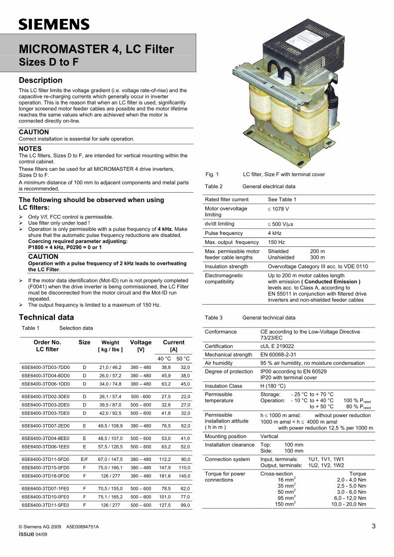
MICROMASTER 4, LC Filter Sizes D to F Description This LC filter limits the voltage gradient (i.e. voltage rate-of-rise) and the capacitive re-charging currents which generally occur in inverter operation. This is the reason that when an LC filter is used, significantly longer screened motor feeder cables are possible and the motor lifetime reaches the same values which are achieved when the motor is connected directly on-line.
CAUTION Correct installation is essential for safe operation.
NOTES The LC filters, Sizes D to F, are intended for vertical mounting within the control cabinet. These filters can be used for all MICROMASTER 4 drive inverters, Sizes D to F. A minimum distance of 100 mm to adjacent components and metal parts is recommended.
The following should be observed when using LC filters:
Only V/f, FCC control is permissible. Use filter only under load ! Operation is only permissible with a pulse frequency of 4 kHz. Make
shure that the automatic pulse frequency reductions are disabled. Coercing required parameter adjusting: P1800 = 4 kHz, P0290 = 0 or 1
CAUTION Operation with a pulse frequency of 2 kHz leads to overheating the LC Filter.
If the motor data identification (Mot-ID) run is not properly completed (F0041) when the drive inverter is being commissioned, the LC Filter must be disconnected from the motor circuit and the Mot-ID run repeated.
The output frequency is limited to a maximum of 150 Hz.
Technical data Table 1 Selection data
Current [A]
Order No. LC filter
Size Weight [ kg / Ibs ]
Voltage [V]
40 °C 50 °C6SE6400-3TD03-7DD0 D 21,0 / 46,2 380 – 480 38,8 32,0
6SE6400-3TD04-8DD0 D 26,0 / 57,2 380 – 480 45,9 38,0
6SE6400-3TD06-1DD0 D 34,0 / 74,8 380 – 480 63,2 45,0 6SE6400-3TD02-3DE0 D 26,1 / 57,4 500 - 600 27,5 22,0
6SE6400-3TD03-2DE0 D 39,5 / 87,0 500 – 600 32,6 27,0
6SE6400-3TD03-7DE0 D 42,0 / 92,5 500 – 600 41,8 32,0 6SE6400-3TD07-2ED0 E 49,5 / 108,9 380 – 480 76,5 62,0 6SE6400-3TD04-8EE0 E 48,5 / 107,0 500 – 600 53,0 41,0
6SE6400-3TD06-1EE0 E 57,5 / 126,5 500 – 600 63,2 52,0 6SE6400-3TD11-5FD0 E/F 67,0 / 147,5 380 – 480 112,2 90,0
6SE6400-3TD15-0FD0 F 75,0 / 166,1 380 – 480 147,9 110,0
6SE6400-3TD18-0FD0 F 126 / 277 380 – 480 181,6 145,0 6SE6400-3TD07-1FE0 F 70,5 / 155,0 500 – 600 78,5 62,0
6SE6400-3TD10-0FE0 F 75,1 / 165,2 500 – 600 101,0 77,0
6SE6400-3TD11-5FE0 F 126 / 277 500 – 600 127,5 99,0
Fig. 1 LC filter, Size F with terminal cover
Table 2 General electrical data
Rated filter current See Table 1
Motor overvoltage limiting
≤ 1078 V
dv/dt limiting ≤ 500 V/μs
Pulse frequency 4 kHz
Max. output frequency 150 Hz
Max. permissible motor feeder cable lengths
Shielded 200 m Unshielded 300 m
Insulation strength Overvoltage Category III acc. to VDE 0110
Electromagnetic compatibility
Up to 200 m motor cables length with emission ( Conducted Emission ) levels acc. to Class A, according to EN 55011 in conjunction with filtered drive inverters and non-shielded feeder cables
Table 3 General technical data
Conformance CE according to the Low-Voltage Directive 73/23/EC
Certification cUL E 219022 Mechanical strength EN 60068-2-31 Air humidity 95 % air humidity, no moisture condensation Degree of protection IP00 according to EN 60529
IP20 with terminal cover Insulation Class H (180 °C) Permissible temperature
Storage: - 25 °C to + 70 °C Operation: - 10 °C to + 40 °C 100 % Prated to + 50 °C 80 % Prated
Permissible installation altitude ( h in m )
h ≤ 1000 m amsl: without power reduction1000 m amsl < h ≤ 4000 m amsl
with power reduction 12,5 % per 1000 mMounting position Vertical Installation clearance Top: 100 mm
Side: 100 mm Connection system Input, terminals: 1U1, 1V1, 1W1
Output, terminals: 1U2, 1V2, 1W2 Torque for power connections
Cross-section Torque 16 mm2 2,0 - 4,0 Nm 35 mm2 2,5 - 5,0 Nm 50 mm2 3,0 - 6,0 Nm 95 mm2 6,0 - 12,0 Nm 150 mm2 10,0 - 20,0 Nm
4 © Siemens AG 2009 A5E00894751A Issue 04/09
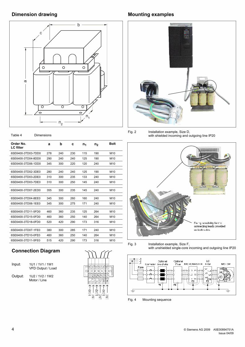
Dimension drawing
Table 4 Dimensions
Order No. LC filter
a b c n1 n2 Bolt
6SE6400-3TD03-7DD0 278 240 230 115 190 M10
6SE6400-3TD04-8DD0 290 240 240 125 190 M10
6SE6400-3TD06-1DD0 345 300 220 120 240 M10
6SE6400-3TD02-3DE0 280 240 240 125 190 M10
6SE6400-3TD03-2DE0 310 300 235 133 240 M10
6SE6400-3TD03-7DE0 310 300 250 145 240 M10
6SE6400-3TD07-2ED0 355 300 235 145 240 M10
6SE6400-3TD04-8EE0 345 300 260 160 240 M10
6SE6400-3TD06-1EE0 345 300 275 171 240 M10
6SE6400-3TD11-5FD0 460 360 235 125 264 M10
6SE6400-3TD15-0FD0 460 360 250 140 264 M10
6SE6400-3TD18-0FD0 520 420 290 173 316 M10
6SE6400-3TD07-1FE0 380 300 285 171 240 M10
6SE6400-3TD10-0FE0 460 360 250 140 264 M10
6SE6400-3TD11-5FE0 515 420 290 173 316 M10
Connection Diagram Input: 1U1 / 1V1 / 1W1 VFD Output / Load Output: 1U2 / 1V2 / 1W2 Motor / Line
Mounting examples
Fig. 2 Installation example, Size D, with shielded incoming and outgoing line IP20
Fig. 3 Installation example, Size F, with unshielded single-core incoming and outgoing line IP20
Fig. 4 Mounting sequence

© Siemens AG 2009 A5E00894755A 3 Issue 04/09
MICROMASTER 4, Sinusoidal Filter Sizes FX and GX
Description This Sinusoidal Filter limits the voltage gradient (i.e. voltage rate-of-rise) and the capacitive re-charging currents which generally occur in inverter operation. The Motor lifetime reaches the same values which are achieved when the motor is connected directly on-line.
CAUTION Correct installation is essential for safe operation.
NOTES The Sinusoidal Filter, Sizes FX to GX , are intended for vertical mounting within the control cabinet. These Sinusoidal Filter can be used by the following type of inverter: MICROMASTER 430/440. A minimum distance of 100 mm to adjacent components and metal parts is recommended.
The following should be observed when using Sinusoidal Filter:
Only V/f, FCC control is permissible. Use filter only under load ! Operation is only permissible with a pulse frequency of 4 kHz. Make
shure that the automatic pulse frequency reductions are disabled. Coercing required parameter adjusting: P1800 = 4 kHz, P0290 = 0 or 1
CAUTION Operation with a pulse frequency of 2 kHz leads to overheating the Sinusoidal Filter.
If the motor data identification (Mot-ID) run is not properly completed (F0041) when the drive inverter is being commissioned, the Sinusoidal Filter must be disconnected from the motor circuit and the Mot-ID run repeated.
The output frequency is limited to a maximum of 150 Hz. Due to higher pulse frequencies when using Sinusoidal Filter a
derating must be implemented (refer to Operating Instructions).
Technical data Table 1 Selection data
Current [A]
Order No. Sinusoidal Filter
Size Weight [kg]
Voltage [V]
40 °C 55 °C
6SL3000-2CE32-3AA0 FX 135 380 … 480 225 191
6SL3000-2CE32-8AA0 GX 138 380 … 480 276 235
6SL3000-2CE33-3AA0 GX 144 380 … 480 333 283
6SL3000-2CE34-1AA0 GX 208 380 … 480 408 347
Fig. 1 Sinusoidal Filter, Size FX
Table 2 General electrical data
Rated filter current See Table 1
Motor overvoltage limiting
≤ 1078 V
dv/dt limiting ≤ 500 V/μs
Pulse frequency 4 kHz
Max. output frequency 150 Hz
Max. permissible motor feeder cable lengths
Shielded 300 m Unshielded 450 m
Insulation strength Overvoltage Category III acc. to VDE 0110
Electromagnetic compatibility
Up to 150 m motor cables lengthwith emission levels ( Conducted Emission ) acc. to Class A, according to EN 55011 in conjunction with filtered drive inverters and non-shielded feeder cables
Table 3 General technical data
Conformance CE according to the Low-Voltage Directive 73/23/EC
Certification cUL E 219022 Mechanical strength EN 60068-2-31 Air humidity 95 % air humidity, no moisture condensation Degree of protection IP00 Insulation Class H (180 °C) Permissible temperature
Storage: - 40 °C to + 70 °C Operation: - 10 °C to + 40 °C 100 % Prated to + 55 °C 85 % Prated
Permissible installation altitude (h in m)
h ≤ 2000 m amsl: without power reduction2000 m amsl < h ≤ 4000 m amsl
with power reduction 7,5 % per 1000 mMounting position Vertical Installation clearance Top: 100 mm
Side: 100 mm Connection system Input, bus bar: 1U1,1V1, 1W1
Output, bus bar: 1U2, 1V2, 1W2 The bus barr terminals are prepared for screws M12
Torque for power connections 14,0 up to 31,0 Nm

4 © Siemens AG 2009 A5E00894755A Issue 04/09
Dimension drawing
Order No. Sinusoidal Filter a b c n1 n2 n3 n4
6SL3000-2CE32-3AA0 300 620 320 280 105 225 150
6SL3000-2CE32-8AA0 300 620 320 280 105 225 150
Order No. Sinusoidal Filter a b c n1 n2 n3 n4
6SL3000-2CE33-3AA0 370 620 360 320 105 225 150
6SL3000-2CE34-1AA0 370 620 360 320 105 225 150
L3L2L1
PE
MICROMASTER
PE
L3
L2
L1
U
V
W
MOTOR
PE
LCFilter
1U1
1V1
1W1
PE
1U2
1V2
1W2
FuseContactor
Optional Filter
Optionalline choke
Fig. 2 Mounting sequence