
Microhardness Tester 2100 Series...
59
MICROMET ® 2100 SERIES MICROHARDNESS TESTER MA2100-3 10/29/2001
-
Upload
dinhkhuong -
Category
Documents
-
view
232 -
download
1
Transcript of Microhardness Tester 2100 Series...

MICROMET® 2100 SERIES MICROHARDNESS TESTER
MA2100-3 10/29/2001

Declaration of Conformity
Manufacturer: BUEHLER, Ltd.
Of: 41 Waukegan Road Lake Bluff, Illinois 60044
Declares the following product: MICROMET® 2100 Series To be in accordance with EC Directive(s); Safety of Machinery: EMC Directive:
89/392/EEC and 91/368/EEC and 93/44/EEC according to the following standards:
89/336/EEC and 92/231/EEC according to the following standards:
EN 292 PART 1 1991 EN 292 PART 2 1991 EN 60204 PART 1 1993
EN 50081-1: 1992 EN 50082-1: 1992
Position: Director of Engineering
Name: Arnie Buchanan
Signature: Arnie Buchanan Date: 10/29/2001
This Manual is a custom generated document. It includes all revisions relative to this specific BUEHLER item as of the date shown below. MICROMET®2100 is a registered trademark of Buehler, Ltd.
The items covered in this communication including all attachments may be subject to the export laws of the United States of America, including without limitation the Export Administration Regulations and the Office of Foreign Asset Control Regulations. The export, re-export or diversion of these items in contravention of these or other applicable regulations is strictly prohibited.
This information contained in this communication is intended only for the use of the individual or entity to which it is addressed and may contain information that is privileged, confidential and exempt from disclosure under applicable law.
MA2100-3 10/29/2001

Table of Contents Warranty ...........................................................................................................................................5 Unpacking.........................................................................................................................................6 Assembly ..........................................................................................................................................6 MICROMET® Setup..........................................................................................................................7 Operation of MICROMET® 2101 ......................................................................................................9 Measurement of Standard Model MICROMET® 2101 ...................................................................11
Caution.....................................................................................................................................12 Maintenance of Standard Model MICROMET® 2101.....................................................................13
Alignment of Standard Model MICROMET® 2101...................................................................13 Indentation Centering .....................................................................................................................14 Measuring Microscope ...................................................................................................................15 Specimen........................................................................................................................................16
Specimen shape................................................................................................................16 Specimen Preparation .......................................................................................................16 Microstructural Etching......................................................................................................17 Specimen thickness...........................................................................................................17 Flat specimen if indentation is not Equilateral Square ......................................................17 Curved (spherical or cylindrical) specimen if indentation is not Equilateral Square .........17
Assembly of the MICROMET® 2103 ..............................................................................................18
Operation of the MICROMET® 2103 ..............................................................................................19 Measurement Screen for Digital Models ........................................................................................21
Screen Buttons.........................................................................................................................22 HV Operation.....................................................................................................................23 HK Operation.....................................................................................................................23
Error Messages........................................................................................................................23 Testing ............................................................................................................................................24
Center the Field of View ....................................................................................................24 Vickers Hardness Measurement .......................................................................................25 Knoop Hardness Measurement.........................................................................................26
SET UP, UTILITY, and EDIT Mode Screens for Digital Units ........................................................27 Main Menu Screen .........................................................................................................................28 Set Up Mode Menu Screen ............................................................................................................29
Calendar Screen ......................................................................................................................30 Load Holding Time Screen ......................................................................................................31 Print Mode Screen ...................................................................................................................32
3 MA2101-3 10/29/2001

Hardness Limit Screen.............................................................................................................33 Measuring Screen....................................................................................................................34 Lot Number Screen..................................................................................................................35
Utility Mode Screen ........................................................................................................................36 Select Printer Screen ...............................................................................................................37 RS 232C Transmission Rate and Parity Screen .....................................................................38 Information Screen...................................................................................................................39 Information Input Screen..........................................................................................................40 Select Unit Screen ...................................................................................................................41 Select Calculation Screen........................................................................................................42
Edit Mode Screen ...........................................................................................................................43 Edit Measuring Data Screen ....................................................................................................44 Display Conversion Data Screen.............................................................................................45 Select Conversion Scale Screen .............................................................................................46 Display Total Data Screen .......................................................................................................47 Print Out Mode Screen ............................................................................................................48
Printout Formats .............................................................................................................................49 Precautions and Adjustments.........................................................................................................50
Indenter ....................................................................................................................................50 Cleaning indenter ..............................................................................................................50 Replacing indenter.............................................................................................................50 Adjusting indentation center ..............................................................................................51 Adjust the object lens position to move the D1 and D2 indentations to the center of indentation rotation. ...........................................................................................................51 Adjust t Data Edit Mode the center of indentation to the center of the visual field............52
Microscope Bulb Replacement.......................................................................................................54 Before Requesting Repair Services ...............................................................................................55 Accessories and Supplies ..............................................................................................................56
Indenters/Hardness Conversion Tables ..................................................................................56 Objectives ................................................................................................................................56 Miscellaneous ..........................................................................................................................56 Test Blocks (Vickers) ..............................................................................................................56 Test Blocks (Knoop)................................................................................................................57 Test Blocks (Dual)...................................................................................................................57
Repackaging...................................................................................................................................58
4 MA2101-3 10/29/2001

Operation and Maintenance Instructions BUEHLER®
MICROMET ® 2100 SERIES MICROHARDNESS TESTER
MICROMET ® 2100 SERIES SPECIFICATIONS
MICROMET ® 2101 • Manual nosepiece • Manual filar
MICROMET ® 2103 • Digital unit • Manual nosepiece • RS232 output • Built-in data storage and conversions
MICROMET ® 2104 • Digital unit • Automatic nosepiece rotation • RS232 output • Built-in data storage and conversions
Warranty
This unit is guaranteed against defective material and workmanship for a period of two (2) years from the date of receipt by the customer. The warranty is void if inspection shows evidence of abuse, misuse, or unauthorized repair. This warranty covers only replacement of defective materials.
If for any reason this unit must be returned to Buehler Ltd. for warranty service, please apply for prior authorization with shipping instructions. Please include the following information:
• Customer Purchase Order Number
• Buehler Invoice Number and Date
• Serial Number
• Reason for return
5 MA2101-3 10/29/2001

Unpacking
Carefully unpack and check the contents. If any components are missing or damaged save the packing list and materials then advise the carrier and Buehler Ltd. of the discrepancy.
Assembly
The MICROMET® 2101 should be placed in a room that is clean and has a relatively constant temperature. The location should be free from dust and vibration. It is recommended that the instrument be placed on a rigid wood or steel desk in a controlled laboratory environment.
The MICROMET® 2101 is shipped assembled except for the filar eyepiece and self-leveling vise.
The standard filar eyepiece is included in the black accessory case. Remove the eyepiece from its protective shipping package and place it in the eyepiece tube. Be sure to check the lens for dust or debris. The eyepiece must be fully inserted to provide proper magnification and accurate measurements.
The self-leveling vise is packaged in a white accessory box with the tester. Using an allen wrench, remove the lock screw and bracket from the stage.
Caution: Install the self-leveling vise with the fixing arms in a front-to-back position. Secure the vise in position with the four (4) screws included.
MICROMET® 2101
6 MA2101-3 10/29/2001

MICROMET® Setup
Before operation, the feet of the Microhardness Tester must be screwed into the corners of the tester base. The feet can be found in the black accessory box. Adjust the feet until the tester appears level according to the supplied bubble level.
Next remove the top panel (see Figure 1) to access the weight loading system using a Phillips screwdriver. The MICROMET is shipped without the weights installed. The weight loading system is secured with three (3) brackets and two (2) rubber pads (see Figure 1a). This packaging must be removed prior to operation.
Figure 1 MICROMET® 2101 (top panel removed)
Brackets1 & 2
Weight Saucer
RubberSupport (2) Bracket 3
Figure 1a Diagram to remove brackets and rubber pads
7 MA2101-3 10/29/2001
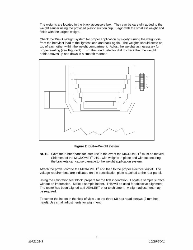
The weights are located in the black accessory box. They can be carefully added to the weight saucer using the provided plastic suction cup. Begin with the smallest weight and finish with the largest weight.
Check the Dial-A-Weight system for proper application by slowly turning the weight dial from the heaviest load to the lightest load and back again. The weights should settle on top of each other within the weight compartment. Adjust the weights as necessary for proper seating (see Figure 2). Turn the Load Selector dial to check that the weight holder moves up and down in a smooth manner.
Figure 2 Dial-A-Weight system
NOTE: Save the rubber pads for later use in the event the MICROMET® must be moved. Shipment of the MICROMET® 2101 with weights in place and without securing the brackets can cause damage to the weight application system.
Attach the power cord to the MICROMET® and then to the proper electrical outlet. The voltage requirements are indicated on the specification plate attached to the rear panel.
Using the calibration test block, prepare for the first indentation. Locate a sample surface without an impression. Make a sample indent. This will be used for objective alignment. The tester has been aligned at BUEHLER® prior to shipment. A slight adjustment may be required.
To center the indent in the field of view use the three (3) hex head screws (2 mm hex head). Use small adjustments for alignment.
8 MA2101-3 10/29/2001
Operation of MICROMET® 2101
Place the specimen to be tested in the vise with the test surface perpendicular to the diamond indenter. If the sample moves during the test or if the impression is not uniform due to improper alignment, the test results should be disregarded and the test repeated.
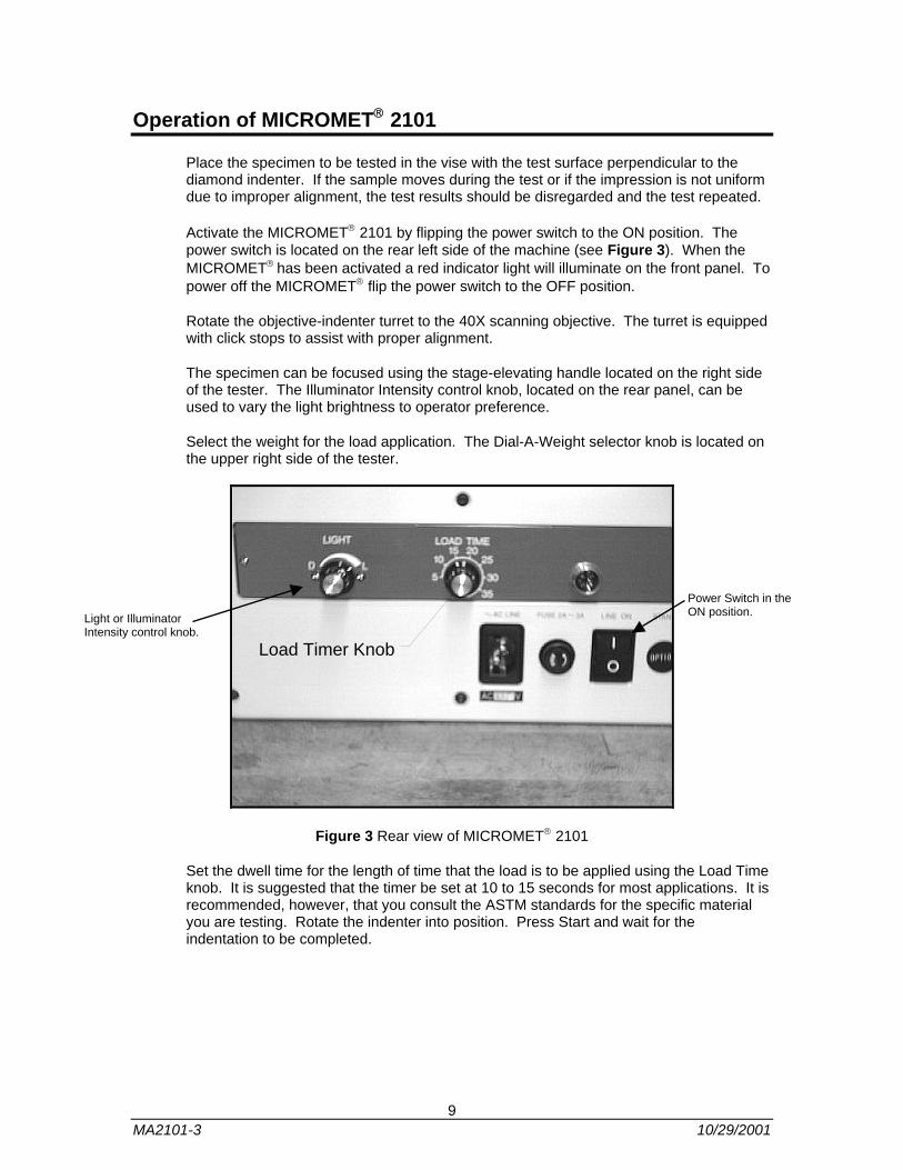
Activate the MICROMET® 2101 by flipping the power switch to the ON position. The power switch is located on the rear left side of the machine (see Figure 3). When the MICROMET® has been activated a red indicator light will illuminate on the front panel. To power off the MICROMET® flip the power switch to the OFF position.
Rotate the objective-indenter turret to the 40X scanning objective. The turret is equipped with click stops to assist with proper alignment.
The specimen can be focused using the stage-elevating handle located on the right side of the tester. The Illuminator Intensity control knob, located on the rear panel, can be used to vary the light brightness to operator preference.
Select the weight for the load application. The Dial-A-Weight selector knob is located on the upper right side of the tester.
Load Timer Knob
Power Switch in the ON position. Light or Illuminator
Intensity control knob.
Figure 3 Rear view of MICROMET® 2101
Set the dwell time for the length of time that the load is to be applied using the Load Time knob. It is suggested that the timer be set at 10 to 15 seconds for most applications. It is recommended, however, that you consult the ASTM standards for the specific material you are testing. Rotate the indenter into position. Press Start and wait for the indentation to be completed.
9 MA2101-3 10/29/2001

Select an area of the sample to be tested. Since the MICROMET® 2101 indentation placement is consistent, the sample can be moved so that the exact point of impression can be selected. The area to be tested should be placed in the center of the field of view (see Figure 4 and Figure 5).
Figure 4 Centering the field of view for a Knoop indent
Figure 5 Centering the field of view for a Vickers indent
10 MA2101-3 10/29/2001
Measurement of Standard Model MICROMET® 2101
Rotate the Objective-Indenter Turret to the 40x Objective. If the impression does not appear in the center of the field of view consult the maintenance instructions.
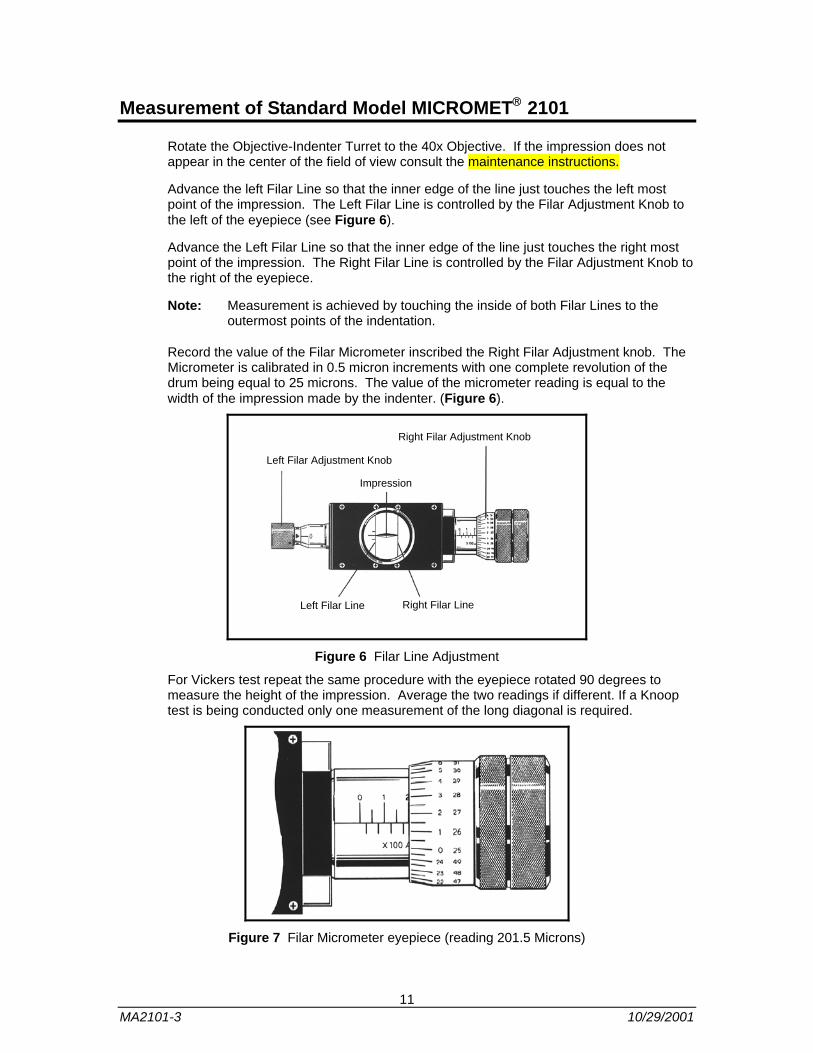
Advance the left Filar Line so that the inner edge of the line just touches the left most point of the impression. The Left Filar Line is controlled by the Filar Adjustment Knob to the left of the eyepiece (see Figure 6).
Advance the Left Filar Line so that the inner edge of the line just touches the right most point of the impression. The Right Filar Line is controlled by the Filar Adjustment Knob to the right of the eyepiece.
Note: Measurement is achieved by touching the inside of both Filar Lines to the outermost points of the indentation.
Record the value of the Filar Micrometer inscribed the Right Filar Adjustment knob. The Micrometer is calibrated in 0.5 micron increments with one complete revolution of the drum being equal to 25 microns. The value of the micrometer reading is equal to the width of the impression made by the indenter. (Figure 6).
Left Filar Line Right Filar Line
Impression
Left Filar Adjustment Knob
Right Filar Adjustment Knob
Figure 6 Filar Line Adjustment
For Vickers test repeat the same procedure with the eyepiece rotated 90 degrees to measure the height of the impression. Average the two readings if different. If a Knoop test is being conducted only one measurement of the long diagonal is required.
Figure 7 Filar Micrometer eyepiece (reading 201.5 Microns)
11 MA2101-3 10/29/2001
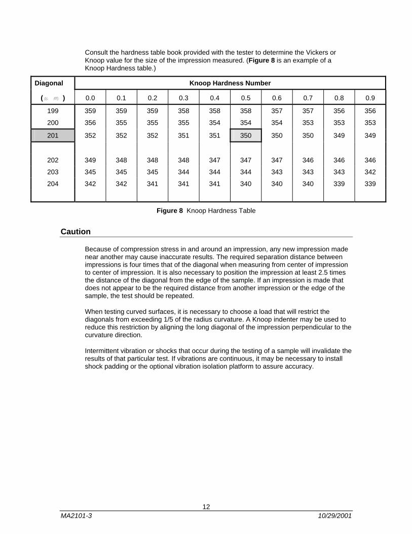
Consult the hardness table book provided with the tester to determine the Vickers or Knoop value for the size of the impression measured. (Figure 8 is an example of a Knoop Hardness table.)
Diagonal Knoop Hardness Number
( ) 0.0 0.1 0.2 0.3 0.4 0.5 0.6 0.7 0.8 0.9
199 359 359 359 358 358 358 357 357 356 356
200 356 355 355 355 354 354 354 353 353 353
201 352 352 352 351 351 350 350 350 349 349
202 349 348 348 348 347 347 347 346 346 346
203 345 345 345 344 344 344 343 343 343 342
204 342 342 341 341 341 340 340 340 339 339
Figure 8 Knoop Hardness Table
Caution
Because of compression stress in and around an impression, any new impression made near another may cause inaccurate results. The required separation distance between impressions is four times that of the diagonal when measuring from center of impression to center of impression. It is also necessary to position the impression at least 2.5 times the distance of the diagonal from the edge of the sample. If an impression is made that does not appear to be the required distance from another impression or the edge of the sample, the test should be repeated.
When testing curved surfaces, it is necessary to choose a load that will restrict the diagonals from exceeding 1/5 of the radius curvature. A Knoop indenter may be used to reduce this restriction by aligning the long diagonal of the impression perpendicular to the curvature direction.
Intermittent vibration or shocks that occur during the testing of a sample will invalidate the results of that particular test. If vibrations are continuous, it may be necessary to install shock padding or the optional vibration isolation platform to assure accuracy.
12 MA2101-3 10/29/2001

Maintenance of Standard Model MICROMET® 2101
The MICROMET® 2101 requires minimal maintenance to provide accurate results for many years. The accuracy of the instrument should be checked periodically against the test block included with each tester.
Maintenance is accomplished by performing a hardness test on the test block and comparing the measurement of the instrument against the known hardness of the test block. If the tester does not agree with the certified value of the block, recalibration may be necessary and can be arranged by calling the Buehler® Ltd. Sales Office nearest you or by contacting Buehler® Headquarters in Lake Bluff, IL at (847) 295-4542. It is recommended that the tester be re-calibrated annually to certify its accuracy.
Alignment of Standard Model MICROMET® 2101
The MICROMET® 2101 is shipped with the indenter and objectives aligned so that the indentations made will appear in the center of the field of view. If the indenter or objectives are replaced or dislocated, it may be necessary to realign the objectives so that the impression is centered.
NOTE: The MICROMET® 2101 Indenter is fixed and cannot be moved or adjusted. Alignment is achieved by moving the objective so that it is centered in relation to the impression.
13 MA2101-3 10/29/2001
Indentation Centering
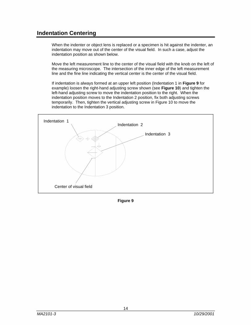
When the indenter or object lens is replaced or a specimen is hit against the indenter, an indentation may move out of the center of the visual field. In such a case, adjust the indentation position as shown below.
Move the left measurement line to the center of the visual field with the knob on the left of the measuring microscope. The intersection of the inner edge of the left measurement line and the fine line indicating the vertical center is the center of the visual field.
If indentation is always formed at an upper left position (Indentation 1 in Figure 9 for example) loosen the right-hand adjusting screw shown (see Figure 10) and tighten the left-hand adjusting screw to move the indentation position to the right. When the indentation position moves to the Indentation 2 position, fix both adjusting screws temporarily. Then, tighten the vertical adjusting screw in Figure 10 to move the indentation to the Indentation 3 position.
Indentation 3
Indentation 2Indentation 1
Center of visual field
Figure 9
14 MA2101-3 10/29/2001

Right and Left adjusting screws
Object lensFront adjusting screw
Figure 10
Adjustment is completed. To move the indentation position to the left, loosen the left-hand screw. To move it up, loosen the vertical adjusting screw. If the right and left adjusting screws are tightened, the vertical adjusting screw does not move. Loosen the right or left adjusting screw slightly.
Measuring Microscope
a. Measurement requires two measurement lines to be adjusted to the apices of an indentation. Thus, the inner edges of the measurement lines must be kept in focus. Diopter adjustment should be checked by each new user of the tester.
b. The measuring microscope should always be fully inserted to the stopper. Use care not to draw it out when turning it by 90 degrees.
c. Keep the object lens and eyepiece clean at all times for easy indentation reading.
If the lenses are dirty and an image is unclear, clean them with a soft cloth moistened with high quality glass cleaner without ammonia. If the lenses are still dirty, detach the objective lens and check it for flaws or scratches. If it is flawed or cracked, replace it.
Keep the eyepiece covered while not in use.
Objects are easily damaged by hitting the specimen or vise.
15 MA2101-3 10/29/2001

Measuring microscope mounting tube
Filament
Figure 11
Place a specimen (or test block) on the stage and focus sample using the measuring microscope. Looking through the measuring microscope adjust the two optical axis-adjusting screws. Remove the filar eyepiece to view the filament and adjust the bulb alignment for proper illumination. (Figure 11)
Adjust the brightness with the brightness control dial to the users preference. Too bright a visual field causes eye fatigue.
Specimen
Specimen shape
Place a specimen so that its surface is at the right angle to the indenter shaft. If a specimen is unstable and could move during measurement, use the vise to secure it. For a thin or fine specimen it is recommended to use a special vise or fixture.
Specimen Preparation
Microhardness testing may be performed on either mounted or un-mounted specimens but the test surface must be parallel to the anvil surface within 50 microns. If the curved surfaces are tested, an appropriate correction must be applied. The surface to be tested must be prepared according to the guidelines described in ASTM E3-80, or as described in the Metals Handbook, Volume 9, Metallography and Microstructures or the BUEHLER DIGEST Volume 20, No. 2 and 3. These methods will produce a polished surface that is bright and free of surface deformation and coarse scratches.
16 MA2101-3 10/29/2001

Microstructural Etching
Micro etching should generally be avoided because it can lead to error from two sources. First, a heavy etch could attack the surface enough to soften it and produce lower hardness values. Second, the darkened surface may make the indentation difficult to see and read because the indentation also appears dark in the microscope.
However, if it is important to locate a particular area as a hardened case, a very light etch may be applied to delineate the phase areas without affecting the hardness values.
Specimen thickness
Each specimen should have a thickness (or the hardened layer thickness for a surface hardened specimen) ten times as large as the indentation depth. Since the indentation depth is approximately 1/7 of the diagonal length, the specimen thickness should be more than approximately 1.5 times as large as the diagonal length of an indentation.
At any rate, the rear surface of a specimen must be free from deformation caused by indentation.
Flat specimen if indentation is not Equilateral Square
Failure to make an equilateral square indentation on a flat specimen may be caused by surface roughness or unevenness. If indentations formed at different positions are deformed in the same direction, the specimen is tilted. Place a specimen so that its surface is at the right angle to the indenter shaft. For the tilted specimen, it is recommended to use a specimen-inclining device (option) to get level surface.
Curved (spherical or cylindrical) specimen if indentation is not Equilateral Square
Failure to make an equilateral square indentation in a curved specimen may be caused by discordance of the curve vertex and the indenter. Move the microtest table for careful centering then retry testing.
17 MA2101-3 10/29/2001
MICROMET®2103
Assembly of the MICROMET® 2103
The MICROMET® 2103 should be placed in a room that is clean and has a relatively constant temperature. The location should be free from dust and vibration. It is recommended that the instrument be placed on a rigid wood or steel desk in a controlled laboratory environment.
The MICROMET® 2103 is shipped assembled except for the filar eyepiece and self-leveling vise.
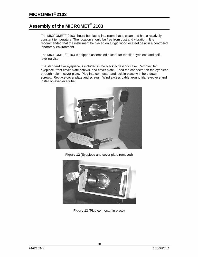
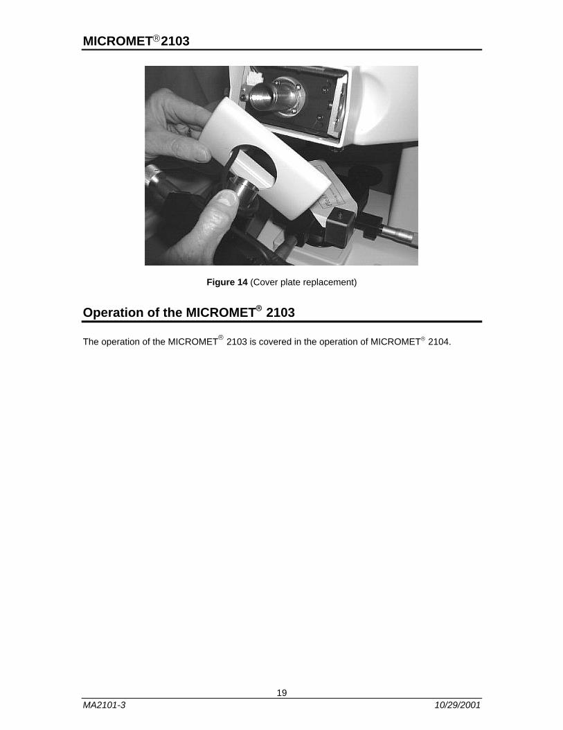
The standard filar eyepiece is included in the black accessory case. Remove filar eyepiece, front cover plate screws, and cover plate. Feed the connector on the eyepiece through hole in cover plate. Plug into connector and lock in place with hold-down screws. Replace cover plate and screws. Wind excess cable around filar eyepiece and install on eyepiece tube.
Figure 12 (Eyepiece and cover plate removed)
Figure 13 (Plug connector in place)
18 MA2101-3 10/29/2001
MICROMET®2103
Figure 14 (Cover plate replacement)
Operation of the MICROMET® 2103
The operation of the MICROMET® 2103 is covered in the operation of MICROMET® 2104.
19 MA2101-3 10/29/2001
MICROMET ® 2104
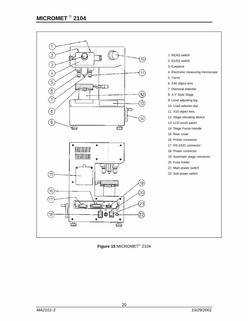
1 READ switch
2 D1/D2 switch
3 Eyepiece
4 Electronic measuring microscope
5 Turret
6 X40 object lens
7 Diamond indenter
8 X-Y Style Stage
9 Level adjusting leg
10 Load selector dial
11 X10 object lens
12 Stage elevating device
13 LCD touch panel
14 Stage Focus Handle
15 Rear cover
16 Printer connector
17 RS-232C connector
18 Power connector
19 Automatic stage connector
20 Fuse holder
21 Main power switch
22 Sub power switch
Figure 15 MICROMET® 2104
20 MA2101-3 10/29/2001
MICROMET ® 2104
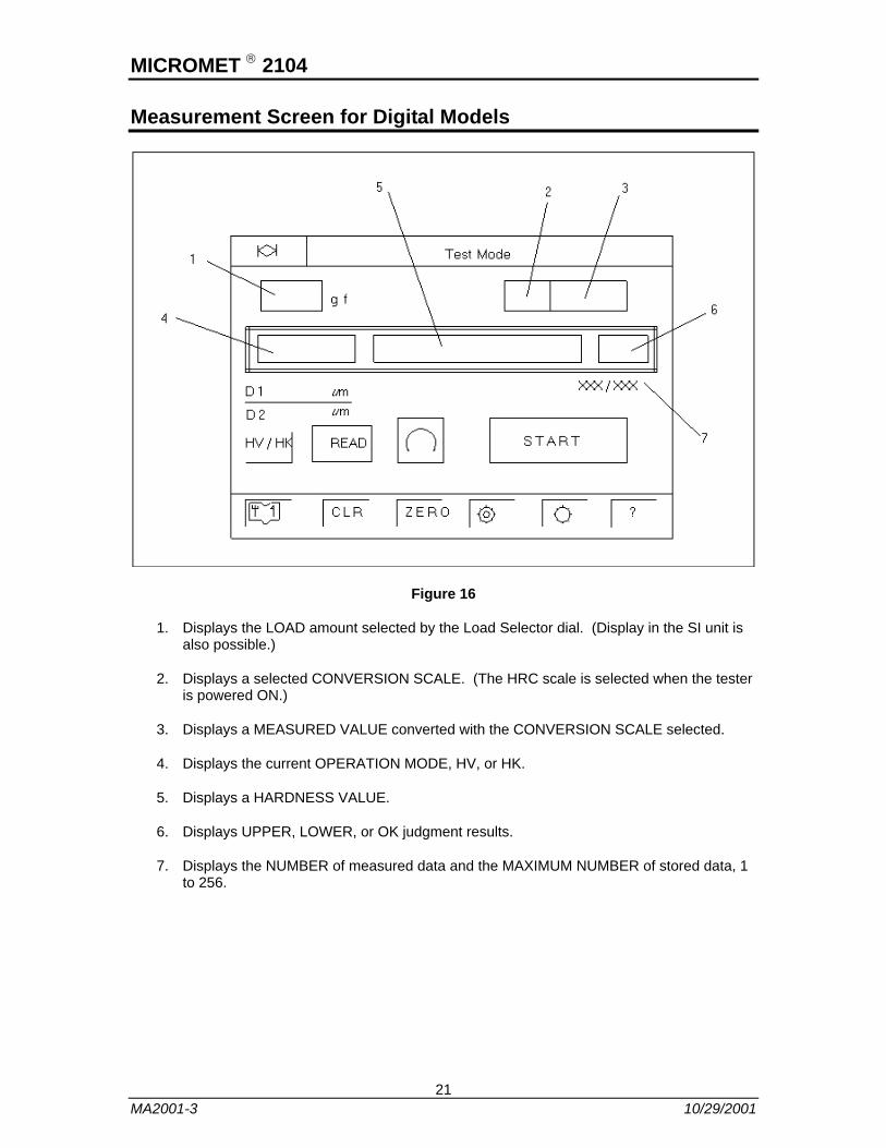
Measurement Screen for Digital Models
Figure 16
1. Displays the LOAD amount selected by the Load Selector dial. (Display in the SI unit is also possible.)
2. Displays a selected CONVERSION SCALE. (The HRC scale is selected when the tester is powered ON.)
3. Displays a MEASURED VALUE converted with the CONVERSION SCALE selected.
4. Displays the current OPERATION MODE, HV, or HK.
5. Displays a HARDNESS VALUE.
6. Displays UPPER, LOWER, or OK judgment results.
7. Displays the NUMBER of measured data and the MAXIMUM NUMBER of stored data, 1 to 256.
21 MA2001-3 10/29/2001
MICROMET ® 2104
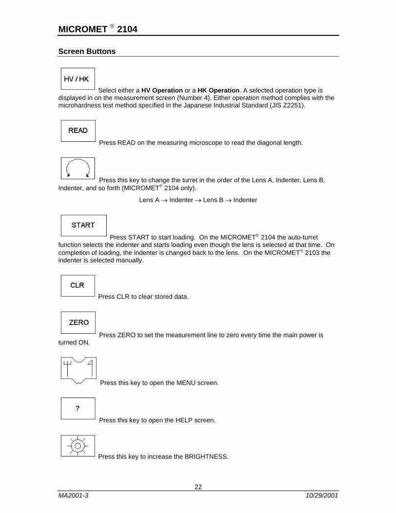
Screen Buttons
Select either a HV Operation or a HK Operation. A selected operation type is displayed in on the measurement screen (Number 4). Either operation method complies with the microhardness test method specified in the Japanese Industrial Standard (JIS Z2251).
Press READ on the measuring microscope to read the diagonal length.
Press this key to change the turret in the order of the Lens A, Indenter, Lens B, Indenter, and so forth (MICROMET® 2104 only).
Lens A → Indenter → Lens B → Indenter
Press START to start loading. On the MICROMET® 2104 the auto-turret function selects the indenter and starts loading even though the lens is selected at that time. On completion of loading, the indenter is changed back to the lens. On the MICROMET® 2103 the indenter is selected manually.
Press CLR to clear stored data.
Press ZERO to set the measurement line to zero every time the main power is turned ON.
Press this key to open the MENU screen.
Press this key to open the HELP screen.
Press this key to increase the BRIGHTNESS.
22 MA2001-3 10/29/2001
MICROMET ® 2104
Press this key to decrease the BRIGHTNESS.
HV Operation
When Diagonal 1 (D1) and Diagonal 2 (D2) values are read the HV operation is executed. In Measurement Mode, the current Diagonal 1 or Diagonal 2 value blinks on the display.
Pressing the READ key in the HV operation mode rotates the measurement diagonal length from D1 to D2 or vice versa. (This function is available on the MICROMET® 2103 only.)
HK Operation
When the longer diagonal length is read the HK operation is executed. In the Measurement Mode only the D1 value blinks on the display.
By pressing the D1/D2 key on the measuring microscope, the indentation observed through the microscope is rotated 90 degrees without rotating the microscope. (This function is available on the MICROMET® 2104 only.)
Error Messages
In the event of a Motor or Sensor error, the following error messages will be displayed.
ERR3 • • Load Motor or Sensor error
ERR7 • • Turret Motor or Sensor error
ERR8 • • Finder Motor or Sensor error
Load missing position • • Loading dial set at improper position.
NOTE: When an error occurs, press the ? (HELP) key for the help screen.
23 MA2001-3 10/29/2001
MICROMET ® 2104
Testing
Before starting a test verify the adjustment and settings of the machine.
a. Control the brightness of the microscope visual field with the brightness control key on the LCD panel. Too bright of a visual field causes eye fatigue. We recommend that you turn down the brightness slightly for long-term observations.
b. Turn the eyepiece until the inner edges of two measurement lines in the visual field are observed clearly (Diopter adjustment).
c. Select a proper test load suitable to the specimen with the Load Selector dial.
d. Set the Dwell Time on the Load Holding Time Setting screen.
When the adjustments are completed start testing.
1. Place a specimen on the micro test table. If the specimen is unstable, secure it with the self-leveling vise supplied with the tester. Whether the self-leveling vise is used or not, the specimen should be maintained with great care so that its surface is always at the right angle to the diamond indenter.
2. Rotate the stage focus handle slowly to bring the specimen surface into focus. For focusing, bring the specimen surface close to the objective lens then look through the microscope and adjust the specimen until its surface is brought into focus. Move the sample with the X-Y controls table to bring the test point to the center of the field of view.
Use the 10X objective lens for coarse adjustment and then change to the 40X objective lens for measurement.
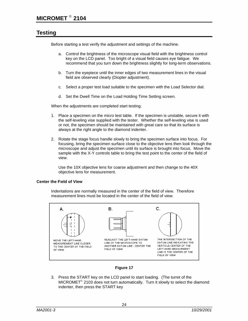
Center the Field of View
Indentations are normally measured in the center of the field of view. Therefore measurement lines must be located in the center of the field of view.
Figure 17
3. Press the START key on the LCD panel to start loading. (The turret of the MICROMET® 2103 does not turn automatically. Turn it slowly to select the diamond indenter, then press the START key
24 MA2001-3 10/29/2001

MICROMET ® 2104
If you use the MICROMET® 2104, the objective lens automatically changes to the diamond indenter, which moves down slowly and is pressed against the specimen surface until the preset test load is applied to the specimen. When the test load is fully applied, the Dwell Time timer starts. When the preset time has passed, the indenter moves up slowly to release the load. The objective is then rotated back for observation and measurement.
The Japanese Industrial Standards recommend dwell time of 10 to 15 seconds.
NOTE: Never touch the turret while the START key is blinking.
4. If you use the MICROMET® 2104, the turret rotates automatically to change the indenter to the 40X objective lens for measurement. If you use the MICROMET® 2103 rotate the turret manually to select the 40X objective lens for measurement. For measurement make sure that the four apices of the indentation are in clear focus.
5. Measure the diagonal length of the indentation.
Vickers Hardness Measurement
Figure 18
Adjust the focus of the inner edges of two measurement lines and four apices of the indentation.
First, turn the knob on the left of the measuring microscope to adjust the inner edge (i.e., right side) of the left measurement line to the left apex of the indentation accurately.
Second, turn the knob on the right of the measuring microscope to adjust the inner edge (i.e. left side) of the right measurement line to the right apex of the indentation accurately.
Then, press the READ key. D1 length is displayed (MICROMET® 2104) on the digital display and the indentation rotates automatically. Carry out the same adjustments for the other diagonal line and press the READ key. D2 length is displayed on the digital display. Then, press the READ key again and a Hardness Value (HV) is displayed. (If you use the MICROMET® 2103, rotate the measuring microscope manually and carry out D2 measurement).
25 MA2001-3 10/29/2001

MICROMET ® 2104
Knoop Hardness Measurement
Figure 19
Adjust the focus of the inner edges of two measurement lines and two apices of the longer diagonal of the indentation.
First, turn the knob on the left of the measuring microscope to adjust the inner edge (i.e. right side) of the left measurement line to the left apex of the indentation accurately.
Second, turn the knob of the right of the measuring microscope to adjust the inner edge (i.e., left side) of the right measurement line to the right apex of the indentation accurately.
Then press the READ key. The diagonal length is entered and a Hardness Value is displayed on the digital display.
Hardness values are normally expressed as:
Vickers hardness: HV 250
Knoop hardness HK 250
Hardness values at a test load of 0.3 kgf for example, is expressed as:
Vickers hardness: 250 HV 0.3
Knoop hardness 250 HK 0.3
26 MA2001-3 10/29/2001
MICROMET ® 2104
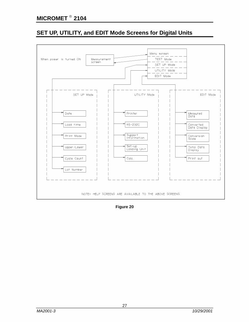
SET UP, UTILITY, and EDIT Mode Screens for Digital Units
Figure 20
27 MA2001-3 10/29/2001
MICROMET ® 2104
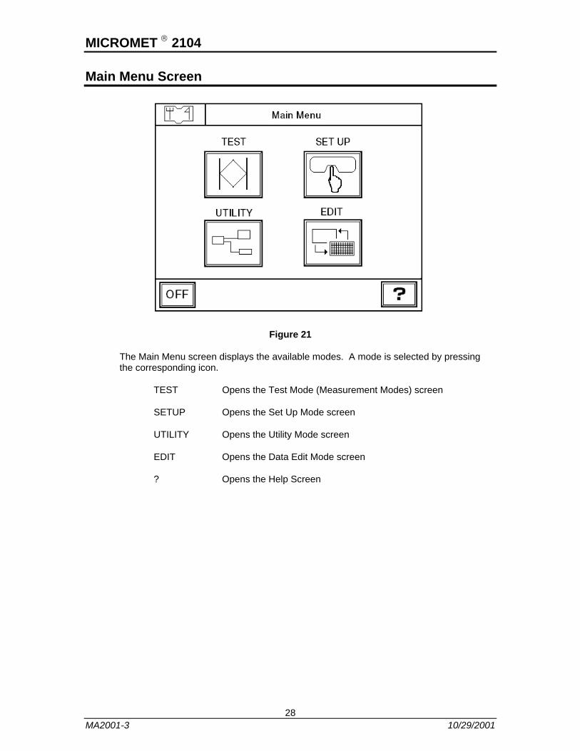
Main Menu Screen
Figure 21
The Main Menu screen displays the available modes. A mode is selected by pressing the corresponding icon.
TEST Opens the Test Mode (Measurement Modes) screen
SETUP Opens the Set Up Mode screen
UTILITY Opens the Utility Mode screen
EDIT Opens the Data Edit Mode screen
? Opens the Help Screen
28 MA2001-3 10/29/2001
MICROMET ® 2104
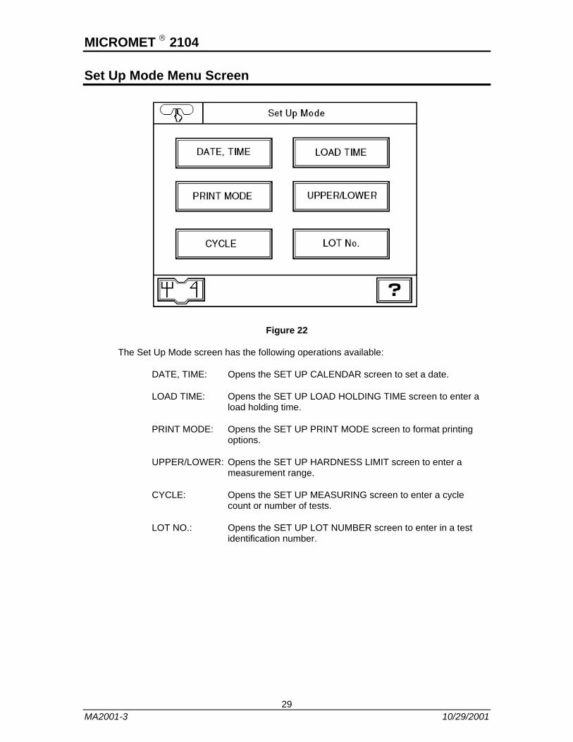
Set Up Mode Menu Screen
Figure 22
The Set Up Mode screen has the following operations available:
DATE, TIME: Opens the SET UP CALENDAR screen to set a date.
LOAD TIME: Opens the SET UP LOAD HOLDING TIME screen to enter a load holding time.
PRINT MODE: Opens the SET UP PRINT MODE screen to format printing options.
UPPER/LOWER: Opens the SET UP HARDNESS LIMIT screen to enter a measurement range.
CYCLE: Opens the SET UP MEASURING screen to enter a cycle count or number of tests.
LOT NO.: Opens the SET UP LOT NUMBER screen to enter in a test identification number.
29 MA2001-3 10/29/2001

MICROMET ® 2104
Calendar Screen
Figure 23
Use the arrow buttons to select the DAY, MONTH, YEAR, HOUR, and MINUTE fields.
Set a value for the selected field using the or key.
When finished press the ENT key to store the selected values.
Press the ESC key to return to the Set Up Mode screen.
The Date and Time set in the Set Up Calendar screen set date will be stored by the backup power supply even after the power is turned off.
30 MA2001-3 10/29/2001

MICROMET ® 2104
Load Holding Time Screen
Figure 24
Use the arrow keys to select a field.
Set a value for the selected field using or key.
The Dwell Time may be set between 5 and 99 seconds in one-second steps. (10 to 15 seconds is recommended)
When finished press the ENT key to store the selected values.
Press the ESC key to return to the Set Up Mode screen.
31 MA2001-3 10/29/2001
MICROMET ® 2104
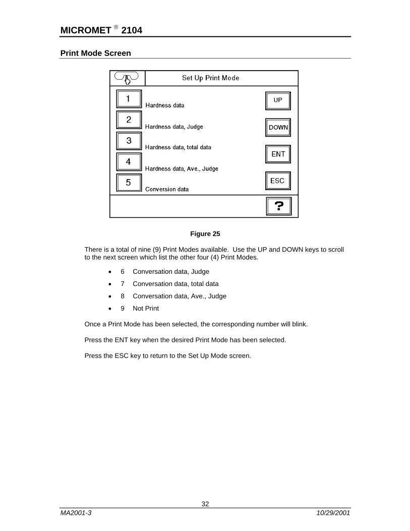
Print Mode Screen
Figure 25
There is a total of nine (9) Print Modes available. Use the UP and DOWN keys to scroll to the next screen which list the other four (4) Print Modes.
• 6 Conversation data, Judge
• 7 Conversation data, total data
• 8 Conversation data, Ave., Judge
• 9 Not Print
Once a Print Mode has been selected, the corresponding number will blink.
Press the ENT key when the desired Print Mode has been selected.
Press the ESC key to return to the Set Up Mode screen.
32 MA2001-3 10/29/2001

MICROMET ® 2104
Hardness Limit Screen
Figure 26
Use the arrow keys to select a field.
Set a value for the selected field using or key.
The UPPER LIMIT and LOWER LIMIT range can be set between 0 and 9999.9.
Press the ENT key when the desired measurement range has been entered.
Press the ESC key to return to the Setup Mode screen.
33 MA2001-3 10/29/2001

MICROMET ® 2104
Measuring Screen
Figure 27
Use the arrow keys to select a field.
Set a value for the selected field using or key.
The Cycle Count values can be between 1 and 256.
Press the ENT key when the value range has been entered.
Press the ESC key to return to the Setup Mode screen.
34 MA2001-3 10/29/2001
MICROMET ® 2104
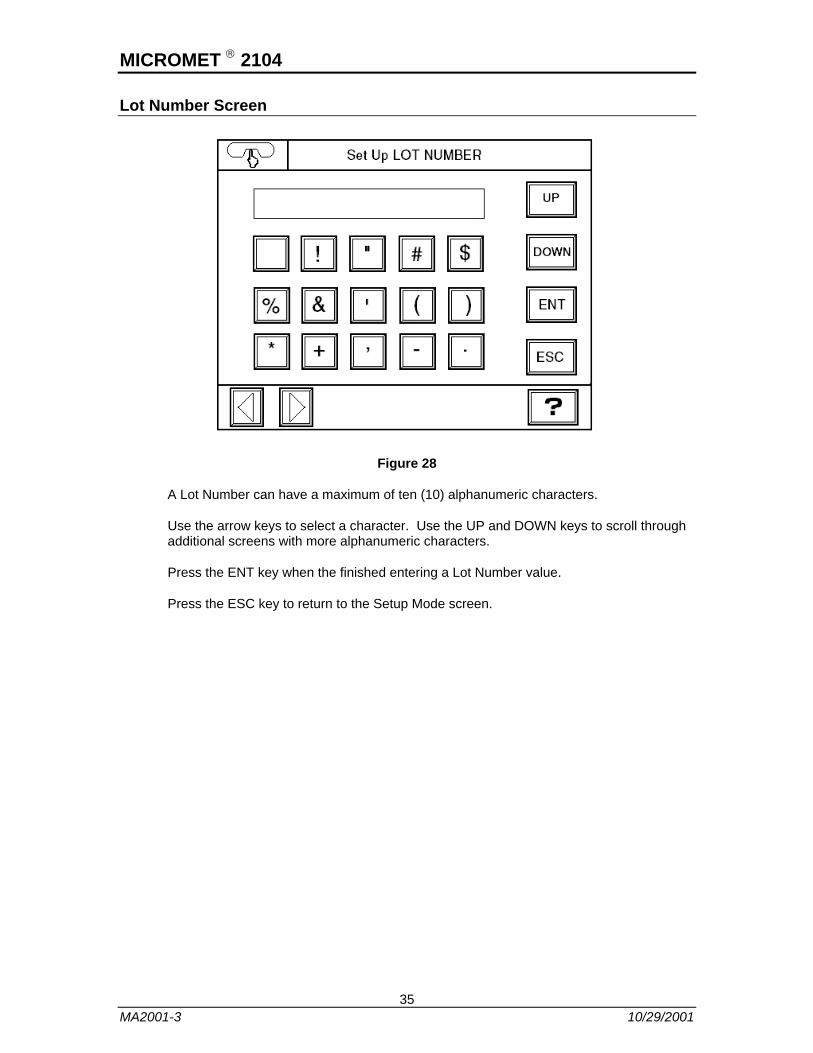
Lot Number Screen
Figure 28
A Lot Number can have a maximum of ten (10) alphanumeric characters.
Use the arrow keys to select a character. Use the UP and DOWN keys to scroll through additional screens with more alphanumeric characters.
Press the ENT key when the finished entering a Lot Number value.
Press the ESC key to return to the Setup Mode screen.
35 MA2001-3 10/29/2001
MICROMET ® 2104
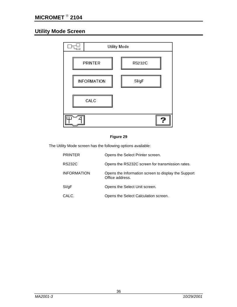
Utility Mode Screen
Figure 29
The Utility Mode screen has the following options available:
PRINTER Opens the Select Printer screen.
RS232C Opens the RS232C screen for transmission rates.
INFORMATION Opens the Information screen to display the Support Office address.
SI/gF Opens the Select Unit screen.
CALC. Opens the Select Calculation screen.
36 MA2001-3 10/29/2001

MICROMET ® 2104
Select Printer Screen
Figure 30
The available printout formats depend on the printer types. Select one of the following printers:
• CENTRO for Centronics printer
• BCD printer
• Serial printer
The select printer will be displayed in the top field.
Press the ENT key to store the selected printer and to return to the Utility Mode screen.
37 MA2001-3 10/29/2001

MICROMET ® 2104
RS 232C Transmission Rate and Parity Screen
Figure 31
Specify the RS232C transmission conditions shown below.
1. Synchronization Start-stop: Start bit: 1 bit
Data bit: 8 bits
Stop bit: 1 bit
2. Transmission rate: 9600, 4800, 2400, or 1200bps
3. Error detection: Even parity or no parity
4. Code: JIS 8-bit code
The select values will be displayed in the top field.
Press the ENT key to store the selected values and to return to the Utility Mode screen.
38 MA2001-3 10/29/2001

MICROMET ® 2104
Information Screen
Figure 32
The Information screen displays the name, address, and telephone number of the Support Office responsible for after sale services.
If you find any problems or have questions, contact the company displayed on the Information screen.
Press the ESC key to return to the Utility Mode screen.
NOTE: Do not press the INPUT key to try to change the setting. If the INPUT key is pressed, the Information Input screen will open.
39 MA2001-3 10/29/2001

MICROMET ® 2104
Information Input Screen
Figure 33
The user should not attempt to set up this screen. Press the ESC key to return to the Information screen.
The name, address, and telephone number of a support company are set on this screen. Each item consists of the following number of characters.
NAME key Company name 25 alphanumeric characters
Adr key Address 90 alphanumeric characters
Tel key Telephone number 20 alphanumeric characters
When the NAME, Adr, or Tel parameter is selected, parameter will be displayed in the upper left corner of the screen.
40 MA2001-3 10/29/2001

MICROMET ® 2104
Select Unit Screen
Figure 34
Select from following load units.
• gf for Grams force units
• SI for Newtonian units
The select value will be displayed in the top field.
The Measurement screen and output through the RS232C interface or to a selected printer will display measurements in the selected unit (gf or SI).
Press the ENT key to return to the Utility Mode screen.
41 MA2001-3 10/29/2001
MICROMET ® 2104
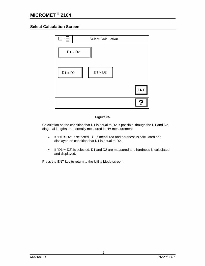
Select Calculation Screen
Figure 35
Calculation on the condition that D1 is equal to D2 is possible, though the D1 and D2 diagonal lengths are normally measured in HV measurement.
• If "D1 = D2" is selected, D1 is measured and hardness is calculated and displayed on condition that D1 is equal to D2.
• If "D1 ≠ D2" is selected, D1 and D2 are measured and hardness is calculated and displayed.
Press the ENT key to return to the Utility Mode screen.
42 MA2001-3 10/29/2001
MICROMET ® 2104
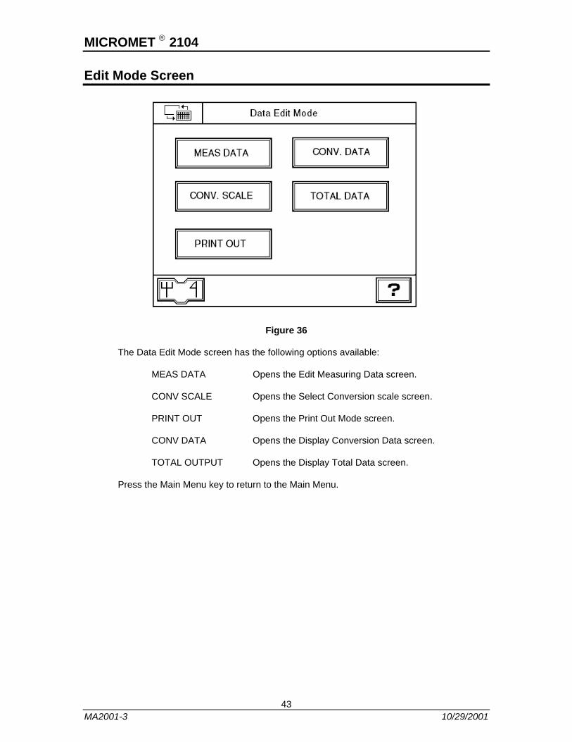
Edit Mode Screen
Figure 36
The Data Edit Mode screen has the following options available:
MEAS DATA Opens the Edit Measuring Data screen.
CONV SCALE Opens the Select Conversion scale screen.
PRINT OUT Opens the Print Out Mode screen.
CONV DATA Opens the Display Conversion Data screen.
TOTAL OUTPUT Opens the Display Total Data screen.
Press the Main Menu key to return to the Main Menu.
43 MA2001-3 10/29/2001

MICROMET ® 2104
Edit Measuring Data Screen
Figure 37
Use the Edit Measuring Data screen to edit measured data.
1. Select a Hardness field by pressing the corresponding numbered button.
2. Select a value with the < or > key.
3. Edit data using the or key.
4. Press the ENT key to enter the edited data.
5. If two or more data fields need to be edited, repeat Steps 1 to 4.
6. To scroll through additional Edit Measuring Data screens use the UP or DOWN key.
7. Press the ESC key to return to the Data Edit Mode screen.
8. To reference data, repeat Step 6.
NOTE: If data is edited, the diagonal length is converted on the condition that D1 is equal to D2 and the converted data is stored.
44 MA2001-3 10/29/2001
MICROMET ® 2104
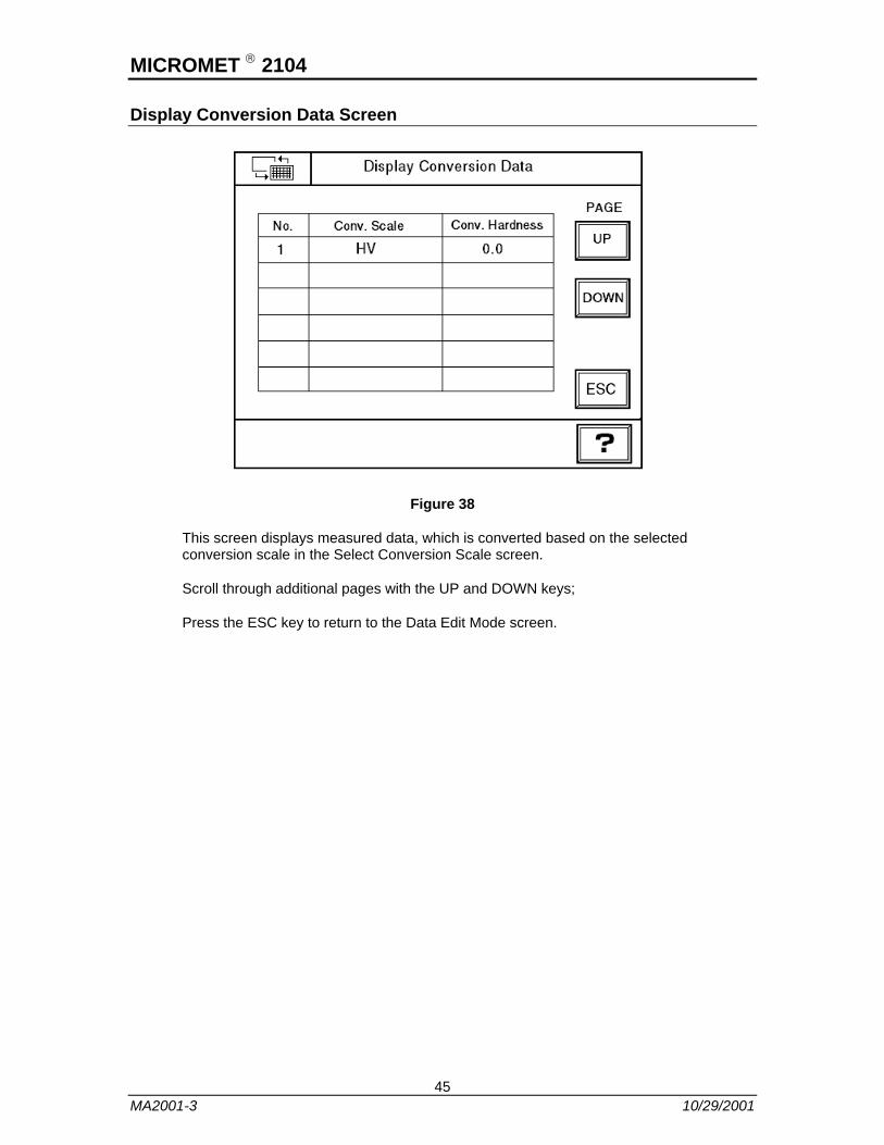
Display Conversion Data Screen
Figure 38
This screen displays measured data, which is converted based on the selected conversion scale in the Select Conversion Scale screen.
Scroll through additional pages with the UP and DOWN keys;
Press the ESC key to return to the Data Edit Mode screen.
45 MA2001-3 10/29/2001

MICROMET ® 2104
Select Conversion Scale Screen
Figure 39
The Select Conversion Scale screen is used to select the type of measurement.
Select a conversion scale (HARD or SOFT) using the key.
The H/S key will change the screen to display to either Hardened Steel or Soft Steel parameters.
HARD
HK HBS HBW HRA
HRB HRC HRD 15N
30N 45N HS TSA
SOFT
HK HBS HRB HRF
HRG HRE HRK 15T
30T 45T HS TSA
Press the ENT key to enter the selected conversion scale.
Press the ESC key to return to the Data Edit Mode screen.
46 MA2001-3 10/29/2001

MICROMET ® 2104
Display Total Data Screen
Figure 40
The Display Total Data screen displays measurement data for the following calculation methods:
• MAX for Maximum
• MIN for Minimum
• RNG for Dispersion
• AVE for Mean Value
• DEV for Standard Deviation
Press the ENT key to return to the Data Edit Mode screen.
47 MA2001-3 10/29/2001

MICROMET ® 2104
Print Out Mode Screen
Figure 41
There is a total of nine (9) Print Out Modes available. Use the UP and DOWN keys to scroll to the next screen which list the other four (4) Print Out Modes.
• 6 Conversation data, Judge
• 7 Conversation data, total data
• 8 Conversation data, Ave., Judge
• 9 Not Print
Press the PRINT key to print the selected data to a printer.
When finished printing, press the ESC to return to the Data Edit Mode screen.
48 MA2001-3 10/29/2001
MICROMET ® 2104
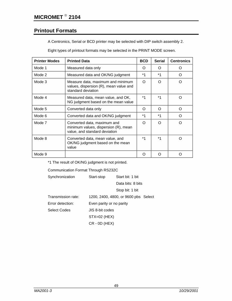
Printout Formats
A Centronics, Serial or BCD printer may be selected with DIP switch assembly 2.
Eight types of printout formats may be selected in the PRINT MODE screen.
Printer Modes Printed Data BCD Serial Centronics
Mode 1 Measured data only O O O
Mode 2 Measured data and OK/NG judgment *1 *1 O
Mode 3 Measure data, maximum and minimum values, dispersion (R), mean value and standard deviation
O O O
Mode 4 Measured data, mean value, and OK, NG judgment based on the mean value
*1 *1 O
Mode 5 Converted data only O O O
Mode 6 Converted data and OK/NG judgment *1 *1 O
Mode 7 Converted data, maximum and minimum values, dispersion (R), mean value, and standard deviation
O O O
Mode 8 Converted data, mean value, and OK/NG judgment based on the mean value
*1 *1 O
Mode 9 O O O
*1 The result of OK/NG judgment is not printed.
Communication Format Through RS232C
Synchronization Start-stop Start bit: 1 bit
Data bits: 8 bits
Stop bit: 1 bit
Transmission rate: 1200, 2400, 4800, or 9600 pbs Select
Error detection: Even parity or no parity
Select Codes JIS 8-bit codes
STX=02 (HEX)
CR - 0D (HEX)
49 MA2001-3 10/29/2001
MICROMET ® 2104
Precautions and Adjustments
Indenter
Cleaning indenter
Always keep the diamond indenter clean. Lightly wipe the indenter tip with a clean cloth to keep out dust or oil. Oil on the indenter tip will result in unclear indentation contours and inaccurate measurements. Wipe the indenter with clean cloth moistened with benzine, alcohol, etc. for secure cleaning.
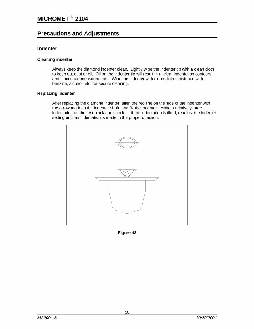
Replacing indenter
After replacing the diamond indenter, align the red line on the side of the indenter with the arrow mark on the indenter shaft, and fix the indenter. Make a relatively large indentation on the test block and check it. If the indentation is tilted, readjust the indenter setting until an indentation is made in the proper direction.
Figure 42
50 MA2001-3 10/29/2001
MICROMET ® 2104
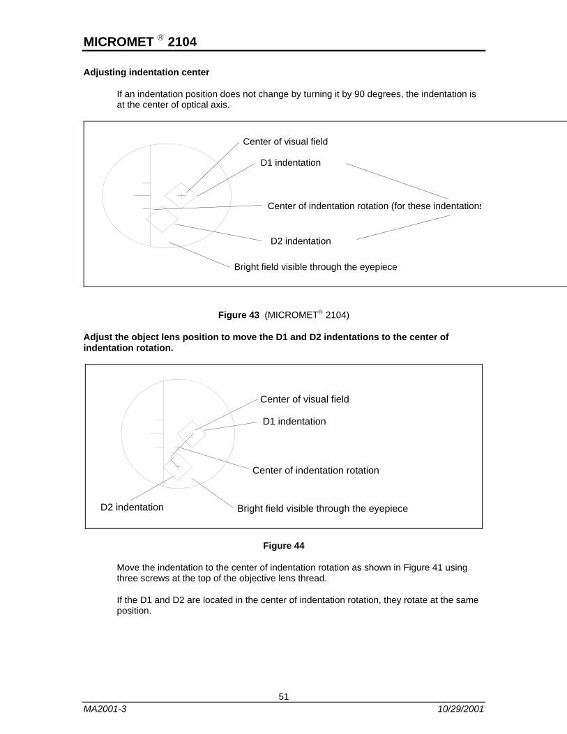
Adjusting indentation center
If an indentation position does not change by turning it by 90 degrees, the indentation is at the center of optical axis.
Center of visual field
D1 indentation
Center of indentation rotation (for these indentations
D2 indentation
Bright field visible through the eyepiece
Figure 43 (MICROMET® 2104)
Adjust the object lens position to move the D1 and D2 indentations to the center of indentation rotation.
Center of visual field
Center of indentation rotation
D1 indentation
Bright field visible through the eyepieceD2 indentation
Figure 44
Move the indentation to the center of indentation rotation as shown in Figure 41 using three screws at the top of the objective lens thread.
If the D1 and D2 are located in the center of indentation rotation, they rotate at the same position.
51 MA2001-3 10/29/2001
MICROMET ® 2104
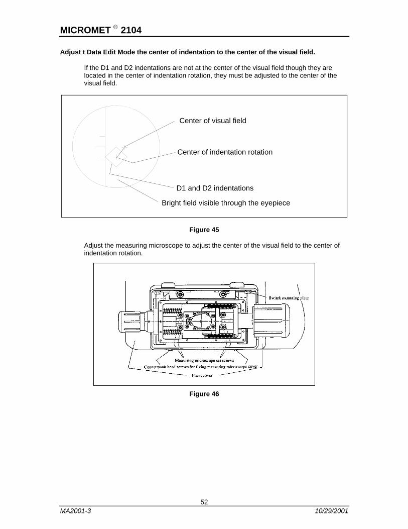
Adjust t Data Edit Mode the center of indentation to the center of the visual field.
If the D1 and D2 indentations are not at the center of the visual field though they are located in the center of indentation rotation, they must be adjusted to the center of the visual field.
Center of visual field
Center of indentation rotation
D1 and D2 indentations
Bright field visible through the eyepiece
Figure 45
Adjust the measuring microscope to adjust the center of the visual field to the center of indentation rotation.
Figure 46
52 MA2001-3 10/29/2001
MICROMET ® 2104
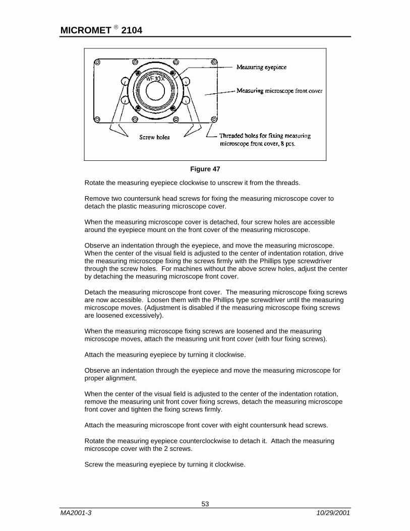
Figure 47
Rotate the measuring eyepiece clockwise to unscrew it from the threads.
Remove two countersunk head screws for fixing the measuring microscope cover to detach the plastic measuring microscope cover.
When the measuring microscope cover is detached, four screw holes are accessible around the eyepiece mount on the front cover of the measuring microscope.
Observe an indentation through the eyepiece, and move the measuring microscope. When the center of the visual field is adjusted to the center of indentation rotation, drive the measuring microscope fixing the screws firmly with the Phillips type screwdriver through the screw holes. For machines without the above screw holes, adjust the center by detaching the measuring microscope front cover.
Detach the measuring microscope front cover. The measuring microscope fixing screws are now accessible. Loosen them with the Phillips type screwdriver until the measuring microscope moves. (Adjustment is disabled if the measuring microscope fixing screws are loosened excessively).
When the measuring microscope fixing screws are loosened and the measuring microscope moves, attach the measuring unit front cover (with four fixing screws).
Attach the measuring eyepiece by turning it clockwise.
Observe an indentation through the eyepiece and move the measuring microscope for proper alignment.
When the center of the visual field is adjusted to the center of the indentation rotation, remove the measuring unit front cover fixing screws, detach the measuring microscope front cover and tighten the fixing screws firmly.
Attach the measuring microscope front cover with eight countersunk head screws.
Rotate the measuring eyepiece counterclockwise to detach it. Attach the measuring microscope cover with the 2 screws.
Screw the measuring eyepiece by turning it clockwise.
53 MA2001-3 10/29/2001
Microscope Bulb Replacement
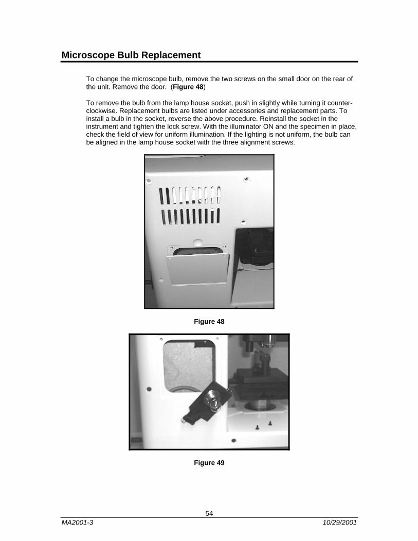
To change the microscope bulb, remove the two screws on the small door on the rear of the unit. Remove the door. (Figure 48)
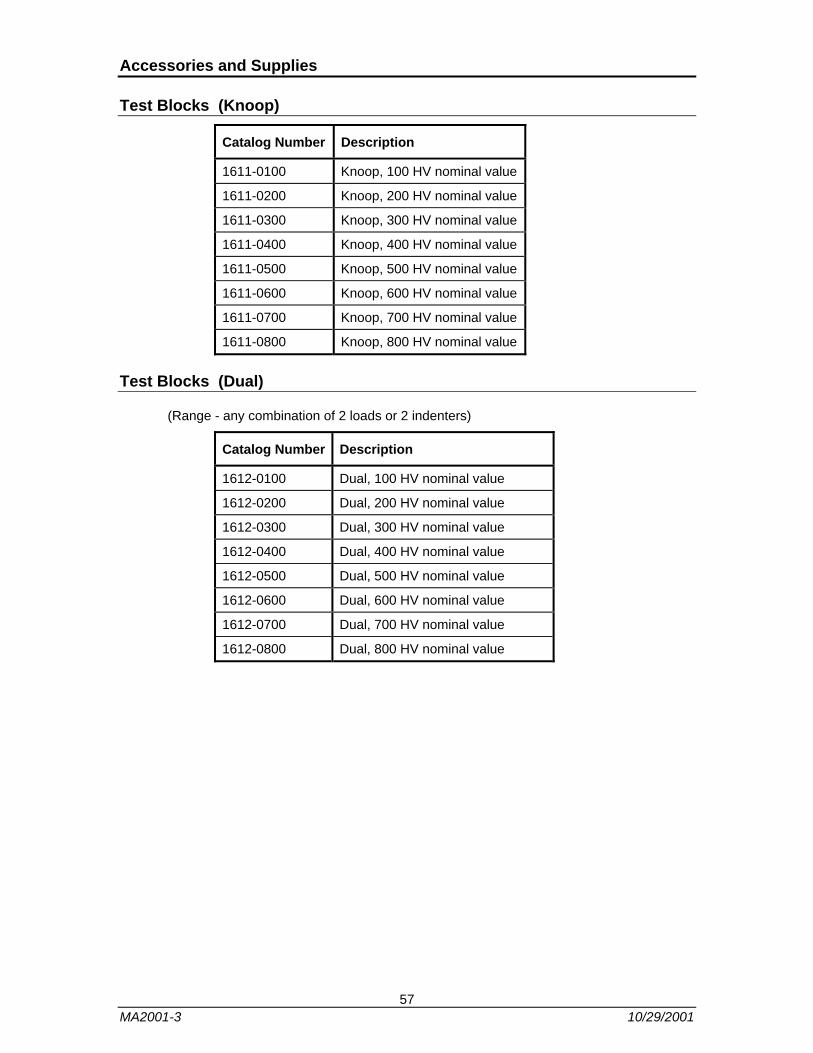
To remove the bulb from the lamp house socket, push in slightly while turning it counter-clockwise. Replacement bulbs are listed under accessories and replacement parts. To install a bulb in the socket, reverse the above procedure. Reinstall the socket in the instrument and tighten the lock screw. With the illuminator ON and the specimen in place, check the field of view for uniform illumination. If the lighting is not uniform, the bulb can be aligned in the lamp house socket with the three alignment screws.
Figure 48
Figure 49
54 MA2001-3 10/29/2001

Before Requesting Repair Services
Before requesting repair service recheck the tester carefully and read through the check Points detailed below. If the tester is still experiencing a problem after reviewing the Check Pointes, contact Buehler or your dealer.
Problem Check Points Actions
Failure to power on. Check if the power cord is connected properly.
Check if the fuse(s) has/have not blown.
Connect power cord to the connector properly.
Replace the fuse(s).
Dim or invisible visual field of microscope.
Check if the lamp hasn't burnt.
Check if the power is on.
See the Microscope Bulb Replacement section in the manual to replace lamp.
Turn the power on.
Failure to move indentation to center of visual field.
See manual section on Precautions and Adjustments to carry out adjustments.
Contact Buehler's service department even if the indentation cannot be moved to the center after adjustment.
Incorrect hardness. Check if the tester is installed on a level surface.
Check the indenter or specimen surface for dirt.
Check if the specimen is not level.
Level the tester using the level.
Wipe the indenter and specimen with a clean cloth or cotton swab moistened with glass cleaner without ammonia.
Fix the specimen at the right angle to the indenter shaft.
Stopping during operation. Check for an error message displayed on the screen.
Check if a power failure or instantaneous power failure occurred.
Check if the motor generates abnormal smell.
Open the Help screen and check the error.
Turn the power off and on once. The motor may burn out. Contact Buehler's service department
55 MA2001-3 10/29/2001

Accessories and Supplies
Accessories and Supplies
Indenters/Hardness Conversion Tables
Catalog Number Description
1600-2200 Vickers Indenter
1600-2201 Knoop Indenter
Objectives
Catalog Number Description
1600-2330 Achromatic M 5X
1600-2331 Achromatic M 10X
1600-2332 Achromatic M 20X
1600-2333 Achromatic M Plan 40X
1600-2334 Achromatic M Plan 100X (Dry)
Miscellaneous
Catalog Number Description
1600-2396 Self Leveling Vise
1600-2353 Microscope Bulb 4.5V, 20W Fiber
1600-2354 Microscope Bulb 4.5V, 17W
Test Blocks (Vickers)
Catalog Number Description
1610-0100 Vickers, 100 HV nominal value
1610-0200 Vickers, 200 HV nominal value
1610-0300 Vickers, 300 HV nominal value
1610-0400 Vickers, 400 HV nominal value
1610-0500 Vickers, 500 HV nominal value
1610-0600 Vickers, 600 HV nominal value
1610-0700 Vickers, 700 HV nominal value
1610-0800 Vickers, 800 HV nominal value
56 MA2001-3 10/29/2001
Accessories and Supplies
Test Blocks (Knoop)
Catalog Number Description
1611-0100 Knoop, 100 HV nominal value
1611-0200 Knoop, 200 HV nominal value
1611-0300 Knoop, 300 HV nominal value
1611-0400 Knoop, 400 HV nominal value
1611-0500 Knoop, 500 HV nominal value
1611-0600 Knoop, 600 HV nominal value
1611-0700 Knoop, 700 HV nominal value
1611-0800 Knoop, 800 HV nominal value
Test Blocks (Dual)
(Range - any combination of 2 loads or 2 indenters)
Catalog Number Description
1612-0100 Dual, 100 HV nominal value
1612-0200 Dual, 200 HV nominal value
1612-0300 Dual, 300 HV nominal value
1612-0400 Dual, 400 HV nominal value
1612-0500 Dual, 500 HV nominal value
1612-0600 Dual, 600 HV nominal value
1612-0700 Dual, 700 HV nominal value
1612-0800 Dual, 800 HV nominal value
57 MA2001-3 10/29/2001
Addendum
Repackaging
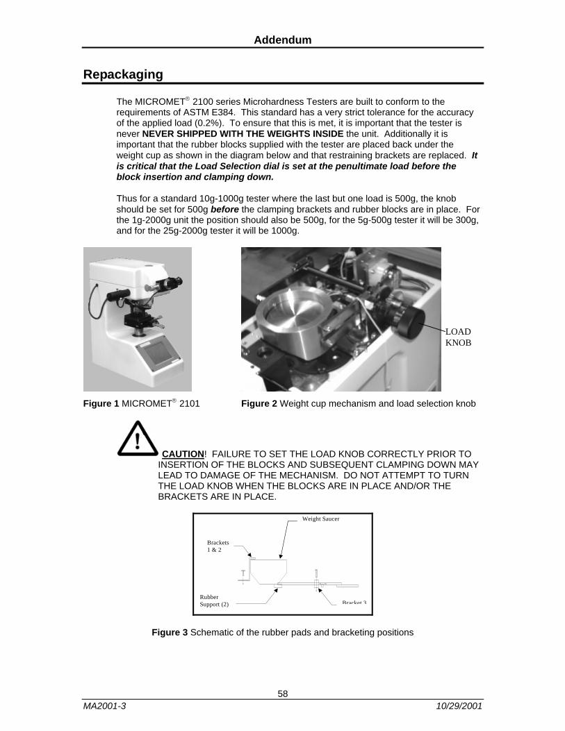
The MICROMET® 2100 series Microhardness Testers are built to conform to the requirements of ASTM E384. This standard has a very strict tolerance for the accuracy of the applied load (0.2%). To ensure that this is met, it is important that the tester is never NEVER SHIPPED WITH THE WEIGHTS INSIDE the unit. Additionally it is important that the rubber blocks supplied with the tester are placed back under the weight cup as shown in the diagram below and that restraining brackets are replaced. It is critical that the Load Selection dial is set at the penultimate load before the block insertion and clamping down.
Thus for a standard 10g-1000g tester where the last but one load is 500g, the knob should be set for 500g before the clamping brackets and rubber blocks are in place. For the 1g-2000g unit the position should also be 500g, for the 5g-500g tester it will be 300g, and for the 25g-2000g tester it will be 1000g.
LOAD KNOB
Figure 1 MICROMET® 2101 Figure 2 Weight cup mechanism and load selection knob
CAUTION! FAILURE TO SET THE LOAD KNOB CORRECTLY PRIOR TO INSERTION OF THE BLOCKS AND SUBSEQUENT CLAMPING DOWN MAY LEAD TO DAMAGE OF THE MECHANISM. DO NOT ATTEMPT TO TURN THE LOAD KNOB WHEN THE BLOCKS ARE IN PLACE AND/OR THE BRACKETS ARE IN PLACE.
Brackets1 & 2
Weight Saucer
Rubber Support (2) Bracket 3
Figure 3 Schematic of the rubber pads and bracketing positions
58 MA2001-3 10/29/2001

Notes
59 MA2001-3 10/29/2001