Microgrid / Smartgrid Research Facility US Department of Energy, Energy Systems Integration Facility...
30
Microgrid/Smartgrid Research Facility US Department of Energy, Energy Systems Integration Facility Photo by Dennis Schroeder, NREL Dave Sereno, PE, LEED AP Kevin Krause, PE, LEED AP 2015 IDEA Conference Clean Campus Energy for the Next Generation Denver, Colorado
-
Upload
aei-affiliated-engineers -
Category
Engineering
-
view
288 -
download
1
Transcript of Microgrid / Smartgrid Research Facility US Department of Energy, Energy Systems Integration Facility...
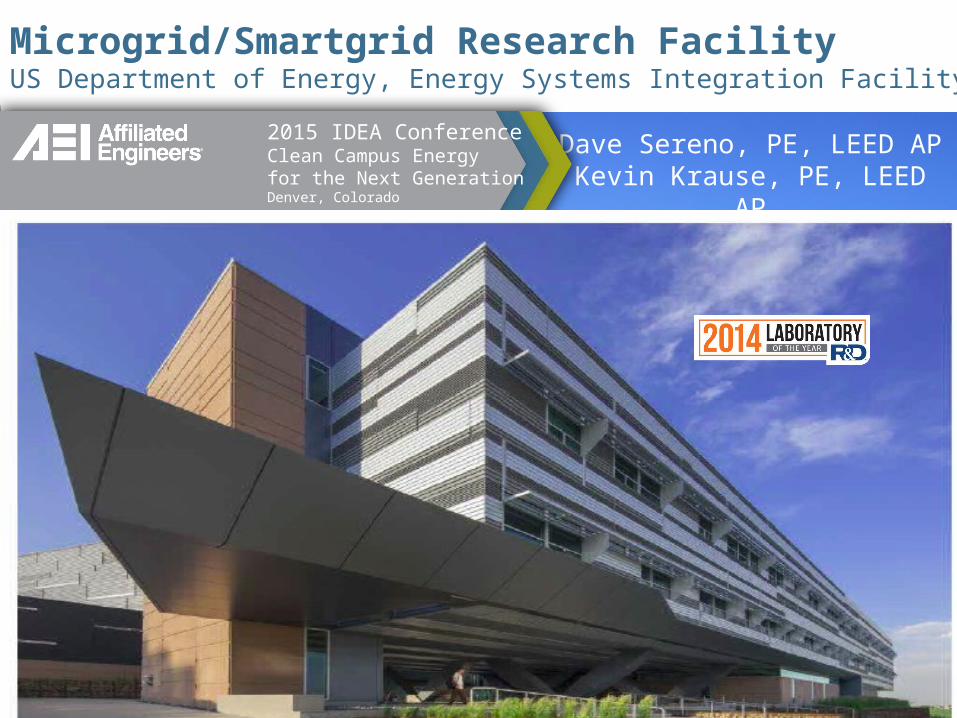
Microgrid/Smartgrid Research FacilityUS Department of Energy, Energy Systems Integration Facility Case Study
Photo by Dennis Schroeder, NREL
Dave Sereno, PE, LEED APKevin Krause, PE, LEED AP
2015 IDEA ConferenceClean Campus Energyfor the Next Generation Denver, Colorado

Learning Objectives
• Understand research and associated infrastructure requirements to advance smartgrids and microgrids.• Understand extents of DC components and
power converters and their associated challenges and hazards.• Understand key component challenges in the
optimization of safe, reliable and sustainable smartgrids and microgrids.
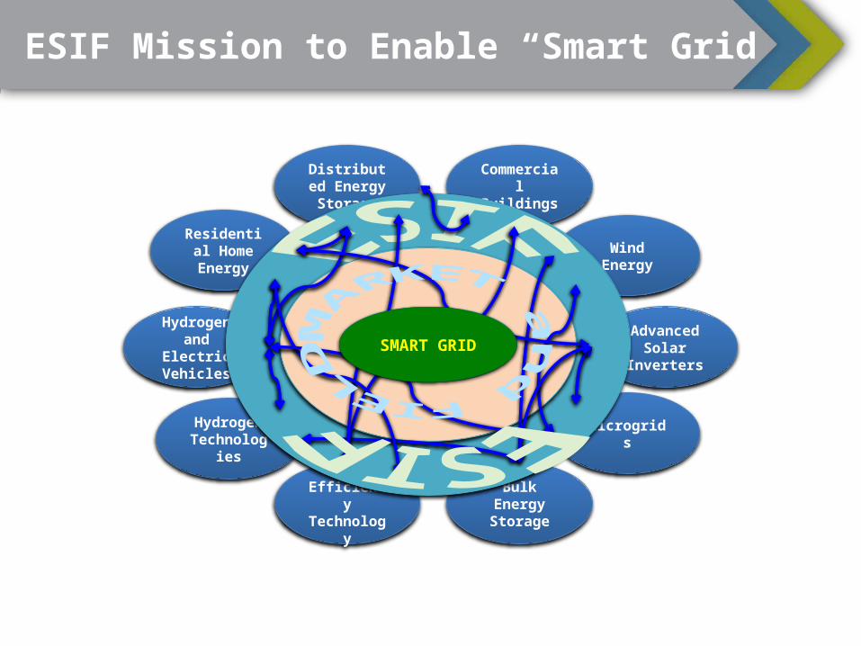
Residential Home Energy
Distributed Energy Storage
Bulk Energy Storage
Advanced Solar
Inverters
Hydrogen Technolog
ies
Commercial
Buildings
Wind Energy
Hydrogen and
Electric Vehicles
Microgrids
Energy Efficiency Technolog
y
ESIF Mission to Enable “Smart Grid”
SMART GRID
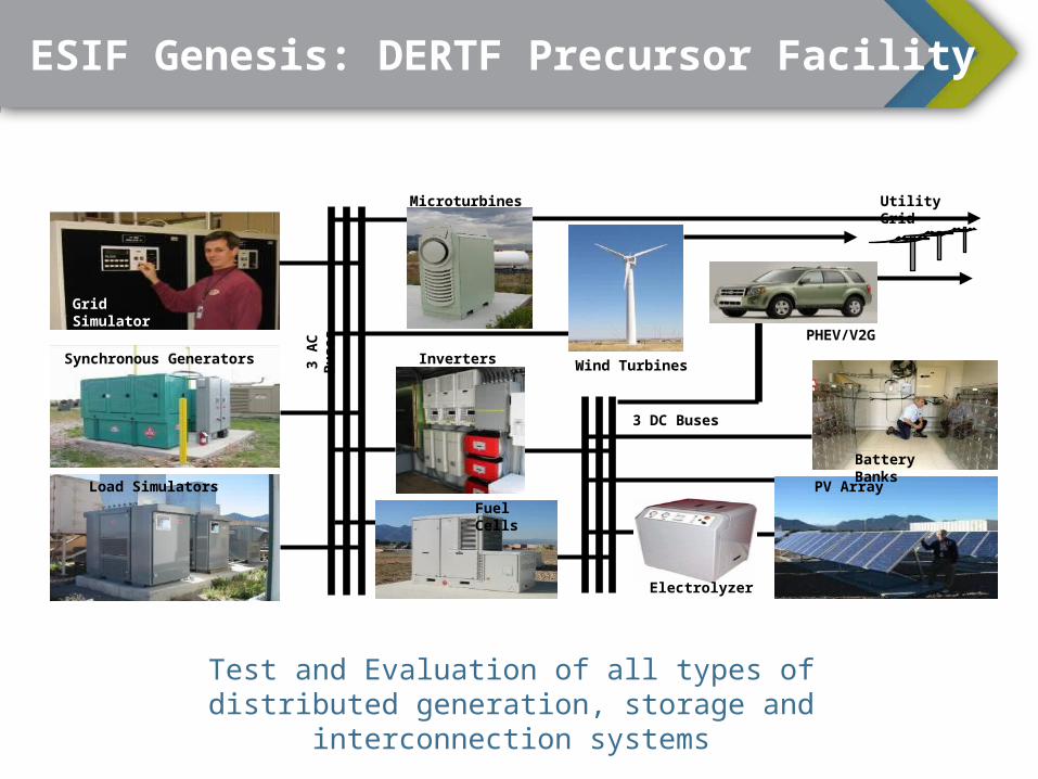
Test and Evaluation of all types of distributed generation, storage and interconnection
systems
Grid Simulator
Load Simulators
Synchronous Generators
PV Array
3 AC
Bu
ses
Utility Grid
Battery Banks
3 DC Buses
Inverters
Fuel Cells
Electrolyzer
Microturbines
Wind Turbines
PHEV/V2G
ESIF Genesis: DERTF Precursor Facility
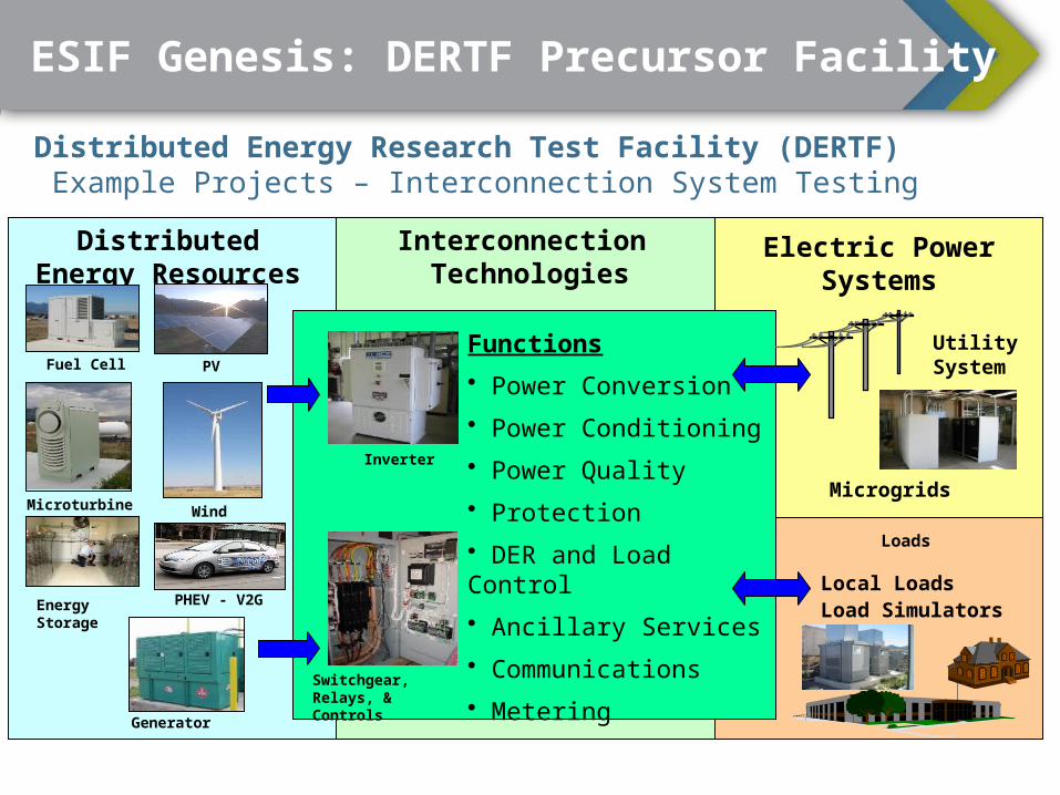
Distributed Energy Research Test Facility (DERTF) Example Projects – Interconnection System Testing
Distributed Energy Resources
Interconnection Technologies
Electric Power Systems
Fuel Cell PV
Microturbine Wind
Generator
Inverter
Switchgear, Relays, & Controls
Functions• Power Conversion• Power Conditioning• Power Quality• Protection• DER and Load Control• Ancillary Services• Communications• Metering
Microgrids
Energy Storage
Loads
Local LoadsLoad Simulators
Utility System
PHEV - V2G
ESIF Genesis: DERTF Precursor Facility
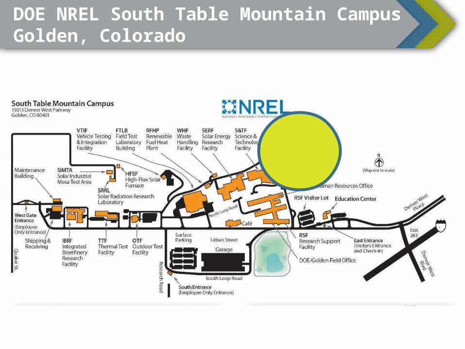
DOE NREL South Table Mountain CampusGolden, Colorado
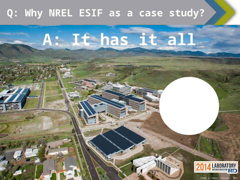
Q: Why NREL ESIF as a case study?
A: It has it all
Photo by Dennis Schroeder, NREL

Three Building Components: East Elevation
Office Data Center
High Bay Laboratories
Photo by Dennis Schroeder, NREL
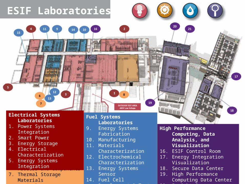
ESIF Laboratories
High Performance Computing, Data Analysis, and Visualization
16. ESIF Control Room17. Energy Integration
Visualization 18. Secure Data Center19. High Performance
Computing Data Center20. Insight Center
Visualization21. Insight Center
Collaboration
Fuel Systems Laboratories
9. Energy Systems Fabrication
10. Manufacturing11. Materials
Characterization12. Electrochemical
Characterization13. Energy Systems Sensor14. Fuel Cell Development
& Test15. Energy Systems High
Pressure Test
Thermal Systems Laboratories
6. Thermal Storage Process and Components
7. Thermal Storage Materials8. Optical Characterization
Electrical Systems Laboratories
1. Power Systems Integration
2. Smart Power3. Energy Storage4. Electrical Characterization5. Energy Systems
Integration
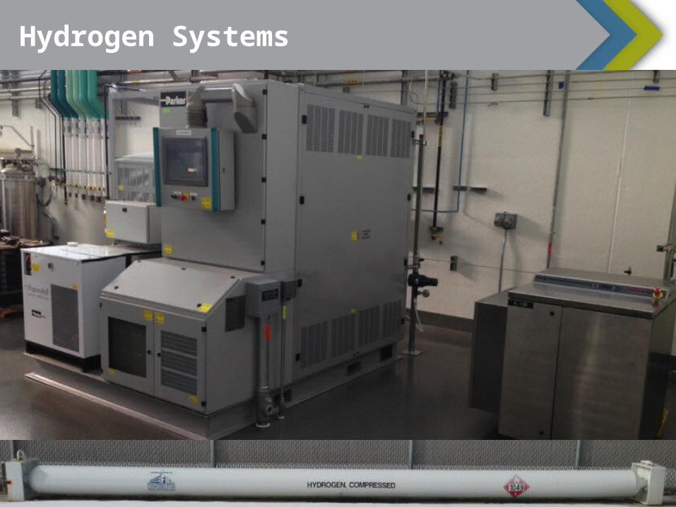
Hydrogen Systems
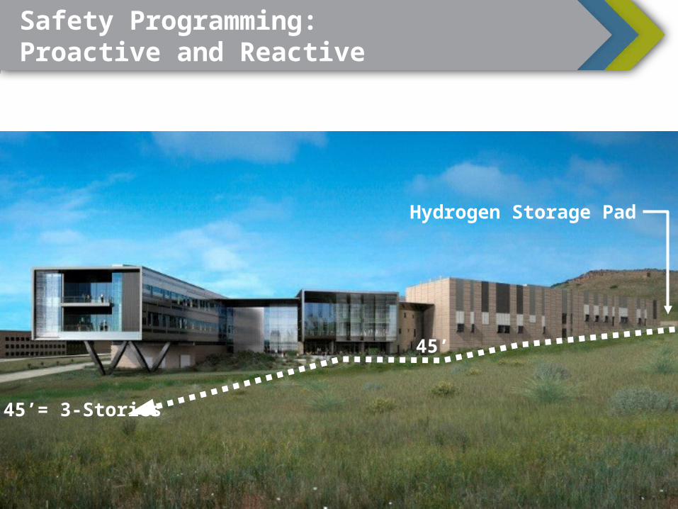
Hydrogen Storage Pad
45’= 3-Stories
45’
Safety Programming: Proactive and Reactive

Conceptual Site Plan
H2 Fueling
Pad
H2Storage
MVOTA LVOTA
ResidentialCommercial
Utility/Grid/Industrial
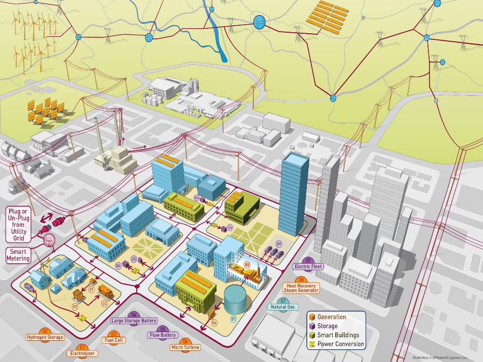
Three Scales:Residential, Commercial & Industrial/Grid

SPLSmart Home Loads
PSILLarge Scale Inverters
PV SimulatorsMicrogrid Power Distribution
ESLEnergy Storage
ESILFuel Cells
Electrolyzer
MVOTAMedium Voltage
Distribution Equipment
Controller
LVOTADiesel Gensets
Programmable Load Banks
Conceptual Connectivity
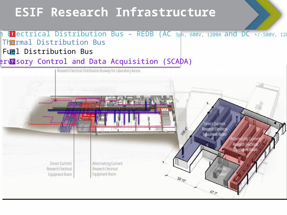
ESIF Research InfrastructureResearch Electrical Distribution Bus – REDB (AC 3ph, 600V, 1200A and DC +/-500V, 1200A)
Thermal Distribution BusFuel Distribution BusSupervisory Control and Data Acquisition (SCADA)

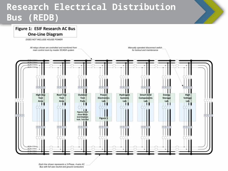
Research Electrical Distribution Bus (REDB)
17

Research Electrical Distribution Bus (REDB)AC• Rated 600Vac 3ϕ, 2ϕ, or 1ϕ• 5-wire design: neutral with
selectable ground bonding location
• 16 Hz to 400 Hz• 250A and 1600A installed• 250A and 2500A planned
(future)• Experiment connection via
cart CB, bus plug CB or fuse, or direct (main lug only)
• Connects PSIL, SPL, ESL, GSE, LBE, LVOTA, MVOTA, ESIL
DC• Rated ±500Vdc or 1000Vdc• 4-wire design: positive,
negative, common, and ground
• Any pole may be tied to ground at selectable location
• 250A and 1600A installed• 250A and 2500A planned
(future)• Experiment connection via
cart contactor/fuse or direct (main lug only)
• Connects PSIL, SPL, ESL, PVE, LVOTA, MVOTA, ESIL
Research Electrical Distribution Bus (REDB)
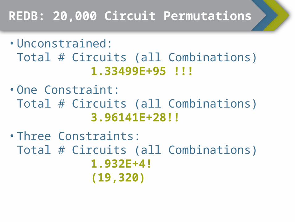
REDB: 20,000 Circuit Permutations
• Unconstrained: Total # Circuits (all Combinations)
1.33499E+95 !!!• One Constraint:
Total # Circuits (all Combinations)3.96141E+28!!
• Three Constraints: Total # Circuits (all Combinations)
1.932E+4! (19,320)

REDB: One Permutation Example

ESIF Laboratory Control Room

ESIF SCADASupervisory Control And Data Acquisition• Electrical
systems• High speed data
capture• Thermal controls• Gas valving and
process controls

IEEE 1547.1 Testing
Abnormal voltage (5.2)Abnormal frequency
(5.3)Synchronization (5.4)DC injection (5.6)Unintentional islanding
(5.7)Reverse power (5.8)Reconnect (5.10)Harmonics (5.11)
Planned Capabilities• Temperature stability (5.1)• Open phase (5.9)
Not Currently Planned• Interconnection integrity (5.5)• Flicker (5.12)

Inverter/Power Electronics Testing Capabilities
• Interconnection Standard Testing (e.g. IEEE 1547) o Over / Under Voltage and Frequencyo Power Qualityo Islanding, etc.
• Steady-state Performance• PLL Response• Maximum Power Point
Tracking• Efficiency• Battery cycling
• Advanced Functionso LVRTo FRTo Volt/VARo Frequency/Watto Volt/Watt
• 4-quadrant Operation• Abnormal Grid Conditions
o Loss of phaseo Sags, Swellso Fault
Basic Advanced

Additional Testing Efforts
• Electric vehicles• Battery energy storage• Other energy storage• Microgrids• Home energy, appliances• Fuel cell vehicles• Hydrogen production and utilization systems

Large Advanced Inverter Development/Testing

Team Participants
DESIGN CONSTRUCTIONSmithGroupJJR Affiliated Engineers, IncMartin & Martin
JE Dunn Construction CompanyMTech MechanicalEncore Electric, Inc.
Courtesy of SmithGroupJJR
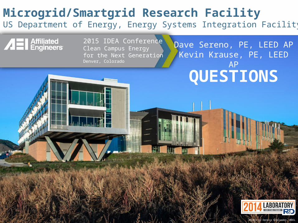
Microgrid/Smartgrid Research FacilityUS Department of Energy, Energy Systems Integration Facility Case Study
QUESTIONS
Photo by Dennis Schroeder, NREL
2015 IDEA ConferenceClean Campus Energyfor the Next Generation Denver, Colorado
Dave Sereno, PE, LEED APKevin Krause, PE, LEED AP