
Microdyn-Nadir Spiral-Wound Element Technical Manual
84
Spiral-Wound Elements Technical Manual
Transcript of Microdyn-Nadir Spiral-Wound Element Technical Manual

Spiral-Wound Elements
Technical Manual

Spiral-Wound Elements | TECHNICAL MANUAL MICRODYN-NADIR | REVISION DATE: 11/12/2020 2
Contact Europe Germany: +49 611 962 6001 Italy: +39 0721 1796201 [email protected]
Americas USA: +1 805 964 8003 [email protected]
Asia Singapore: +65 6457 7533 China: +86 10 8413 9860 [email protected]

Spiral-Wound Elements | TECHNICAL MANUAL MICRODYN-NADIR | REVISION DATE: 11/12/2020 3
Table of Content
1 Membrane Basics .......................................................................................................................... 8
1.1 WHAT IS A MEMBRANE & HOW DO THEY WORK? ........................................................................ 8 1.1.1 What is a Membrane? ..................................................................................................................................8 1.1.2 Osmosis .......................................................................................................................................................8 1.1.3 Reverse Osmosis ........................................................................................................................................ 9
1.2 THE HISTORY OF MEMBRANES ...................................................................................................... 9 1.3 REVERSE OSMOSIS & NANOFILTRATION MEMBRANES ............................................................... 9
1.3.1 Reverse Osmosis ....................................................................................................................................... 10 1.3.2 Nanofiltration ............................................................................................................................................. 10
1.4 RO & NF MEMBRANE CHEMISTRY ................................................................................................. 11 1.4.1 Cellulose Acetate ........................................................................................................................................ 11 1.4.2 Thin-Film Composite ................................................................................................................................. 12
1.5 ULTRAFILTRATION & MICROFILTRATION MEMBRANES .............................................................. 13 1.5.1 Size Exclusion Principles .......................................................................................................................... 13 1.5.2 Ultrafiltration .............................................................................................................................................. 14 1.5.3 Microfiltration ............................................................................................................................................ 15
1.6 UF & MF MEMBRANE CHEMISTRY ................................................................................................ 16 1.6.1 Polyethersulfone ........................................................................................................................................ 16 1.6.2 Polyvinylidene Fluoride ............................................................................................................................. 16 1.6.3 Polyacrylonitrile ......................................................................................................................................... 16 1.6.4 Other Chemistries ...................................................................................................................................... 16
1.7 MEMBRANE FILTRATION PROCESSES ......................................................................................... 16 1.7.1 Dead-End Filtration .................................................................................................................................... 16 1.7.2 Cross-Flow Filtration ................................................................................................................................. 17
1.8 SPIRAL-WOUND ELEMENTS ........................................................................................................... 18 1.8.1 Construction .............................................................................................................................................. 18 1.8.2 Advantages ................................................................................................................................................ 19
2 Membrane Products ................................................................................................................. 21
2.1 REVERSE OSMOSIS (RO) ................................................................................................................ 21 2.2 NANOFILTRATION (NF) ................................................................................................................... 21 2.3 ULTRAFILTRATION (UF) ................................................................................................................. 22 2.4 MICROFILTRATION (MF) ................................................................................................................ 23 2.5 MEMBRANE SUPPORT CHEMICALS ............................................................................................. 23
2.5.1 TriPol™ Antiscalants ................................................................................................................................ 23 TRIPOL™ ANTISCALANTS ......................................................................................................................... 23
2.5.2 TriClean™ Cleaners .................................................................................................................................. 23

Spiral-Wound Elements | TECHNICAL MANUAL MICRODYN-NADIR | REVISION DATE: 11/12/2020 4
TRIPOL™ MEMBRANE CLEANERS ............................................................................................................ 24
3 Pretreatment .............................................................................................................................. 25
3.1 WHAT IS PRETREATMENT & WHEN IS IT NECESSARY? ............................................................. 25 3.1.1 Fouling ...................................................................................................................................................... 25 3.1.2 Scaling ...................................................................................................................................................... 25 3.1.3 Chemical Attack ........................................................................................................................................ 26 3.1.4 Mechanical Damage .................................................................................................................................. 26
3.2 FEED WATER PARAMETERS: ASSESSING RO & NF FEED WATER QUALITY ............................ 26 3.3 PRETREATMENT FOR WATER APPLICATION RO & NF ELEMENTS............................................30
3.3.1 Acid Addition ............................................................................................................................................ 30 3.3.2 Antiscalants / Scale Inhibitors .................................................................................................................. 30 3.3.3 Granular Activated Carbon ........................................................................................................................ 31 3.3.4 Lime Softening ........................................................................................................................................... 31 3.3.5 Ultrafiltration & Microfiltration ................................................................................................................... 31 3.3.6 Multi-Media Filter ....................................................................................................................................... 31 3.3.7 Sodium Bisulfite ....................................................................................................................................... 32 3.3.8 Water Softening ........................................................................................................................................ 32
3.4 CONTROLLING HIGH LEVELS OF SILICA...................................................................................... 32 3.4.1 Silica Pretreatment ................................................................................................................................... 32 3.4.2 Operational Considerations...................................................................................................................... 33 3.4.3 Cleaning Procedure .................................................................................................................................. 33
3.5 CARBONATE SCALE PRETREATMENT ......................................................................................... 33 3.5.1 Determining Scaling Potential .................................................................................................................. 34 3.5.2 Pretreatment ............................................................................................................................................. 34 3.5.3 Operational Considerations...................................................................................................................... 35 3.5.4 Cleaning Procedure .................................................................................................................................. 35
3.6 SULFATE SCALE PRETREATMENT ............................................................................................... 35 3.6.1 Pretreatment ............................................................................................................................................. 36 3.6.2 Operational Considerations...................................................................................................................... 36 3.6.3 Cleaning Procedure .................................................................................................................................. 37
3.7 ALUMINUM PRETREATMENT ......................................................................................................... 37 3.7.1 Causes & Recommendations to Prevent Aluminum Fouling ................................................................... 37
3.8 PHOSPHATE SCALE PRETREATMENT ......................................................................................... 37 TABLE 1. PHOSPHATE COMPOUNDS WITH LOW SOLUBILITIES (ARRANGED FROM MOST SOLUBLE TO LEAST SOLUBLE). ................................................................................................................................ 38
3.8.1 Pretreatment ............................................................................................................................................. 38 3.8.2 Operational Considerations...................................................................................................................... 38 3.8.3 Cleaning Procedure .................................................................................................................................. 38
3.9 IRON, MANGANESE & TRANSITION METALS ............................................................................... 39 3.9.1 Sources of Fouling ................................................................................................................................... 39 3.9.2 Pretreatment ............................................................................................................................................. 39 3.9.3 Operational Considerations...................................................................................................................... 40 3.9.4 Cleaning Procedure .................................................................................................................................. 40
3.10 DECHLORINATION USING SODIUM METABISULFITE ................................................................. 40 3.10.1 Importance of Dechlorination ............................................................................................................... 40 3.10.2 Dosing SMBS Solution ......................................................................................................................... 40 3.10.3 SMBS Dechlorination Reaction ............................................................................................................ 40 3.10.4 Chlorine Monitoring ............................................................................................................................... 41
3.11 CHLORAMINE PRETREATMENT .................................................................................................... 41 3.11.1 Chloramine ................................................................................................................................................ 41
3.12 CHLORINE DIOXIDE PRETREATMENT .......................................................................................... 42

Spiral-Wound Elements | TECHNICAL MANUAL MICRODYN-NADIR | REVISION DATE: 11/12/2020 5
4 System Design ......................................................................................................................... 43
4.1 PERFORMANCE & DESIGN CHARACTERISTICS .......................................................................... 43 4.1.1 System Parameters ................................................................................................................................... 43 4.1.2 Salt Rejection ............................................................................................................................................ 43 4.1.3 Salt Passage ............................................................................................................................................. 43 4.1.4 Recovery ................................................................................................................................................... 43 4.1.5 Concentration Factor ................................................................................................................................ 44 4.1.6 Flux ........................................................................................................................................................... 44 4.1.7 Mass Balance ............................................................................................................................................ 44 4.1.8 Stages & Passes in System Design .......................................................................................................... 45
4.2 TEMPERATURE CORRECTION FACTORS: TRISEP® ELEMENTS ................................................ 47 4.2.1 Temperature Correction Equation ............................................................................................................ 47 4.2.2 Temperature Correction Factors by Membrane Type .............................................................................. 47
TABLE 2. TEMPERATURE CORRECTION FACTORS FOR TRISEP MEMBRANES BY MEMBRANE TYPE. ..................................................................................................................................................................... 47 4.3 TESTING PRIOR TO SYSTEM DESIGN: RO & NF SYSTEMS ......................................................... 47
4.3.1 Flat Cell Testing ........................................................................................................................................ 47 4.3.2 Lab-Scale Element Testing ....................................................................................................................... 48 4.3.3 Pilot Testing .............................................................................................................................................. 48
4.4 MEMBRANE SYSTEM COMPONENTS: RO & NF SYSTEMS .......................................................... 48 4.4.1 Pretreatment Components ....................................................................................................................... 48 4.4.2 Membrane Skid Frame .............................................................................................................................. 48 4.4.3 Pressure Vessels ...................................................................................................................................... 48 4.4.4 Feed Pumps .............................................................................................................................................. 49 4.4.5 Valves ....................................................................................................................................................... 49 4.4.6 Instrumentation & Controls ...................................................................................................................... 49 4.4.7 CIP System ............................................................................................................................................... 49
5 System Operation .................................................................................................................... 50
5.1 LOADING OF PRESSURE VESSELS ............................................................................................. 50 5.1.1 Safety Equipment ..................................................................................................................................... 50 5.1.2 Installation Preparation ............................................................................................................................ 50 5.1.3 Element Loading ....................................................................................................................................... 50
5.2 SHIMMING ELEMENTS .................................................................................................................... 51 5.3 START-UP ........................................................................................................................................ 51
5.3.1 System Start-Up ......................................................................................................................................... 51 TABLE 3. RECOMMENDED CLEANING, SANITIZING, AND FLUSH WATER QUALITY. ............................ 52 TABLE 4. SUGGESTED FLOW RATES DURING CLEANING AND RINSING. ............................................. 52
5.3.2 Heat-Sanitizable Element Start-Up Procedure ......................................................................................... 53 TABLE 5. HEAT-SETTING PROCEDURE FOR TRISEP HEAT-SANITIZABLE RO, NF, UF, AND MF ELEMENTS FOR HIGH PURITY APPLICATIONS. ....................................................................................... 53
5.3.3 RO & NF Process Element Start-Up Procedure ........................................................................................ 54 TABLE 6. START-UP CLEANING PROCEDURE FOR TRISEP® RO & NF ELEMENTS USED IN PROCESS APPLICATIONS. .......................................................................................................................................... 54
5.3.4 UF & MF Process Element Start-Up Procedure ........................................................................................ 54 TABLE 7. START-UP CLEANING PROCEDURE FOR TRISEP AND SPIRA-CEL UF & MF ELEMENTS USED IN FOOD & DAIRY APPLICATIONS. ............................................................................................................ 54
5.3.5 Water Purification Element Start-Up Procedure ....................................................................................... 54 5.4 OPERATING CONDITIONS FOR WATER PURIFICATION ELEMENTS ........................................... 55
5.4.1 Biological Matter ....................................................................................................................................... 55 5.4.2 Chlorine / Bromine .................................................................................................................................... 55
Spiral-Wound Elements | TECHNICAL MANUAL MICRODYN-NADIR | REVISION DATE: 11/12/2020 6
5.4.3 Miscellaneous Chemicals ......................................................................................................................... 55 5.4.4 Solubility Limits ........................................................................................................................................ 55 5.4.5 Suspended Solids ..................................................................................................................................... 55 5.4.6 Silt Density Index ...................................................................................................................................... 55 5.4.7 System Design: Target Flux ..................................................................................................................... 55
TABLE 8. DESIGN RECOMMENDATIONS FOR RO AND NF ELEMENTS. .................................................. 56 5.4.8 Operating Conditions: Flow Rates ........................................................................................................... 56
TABLE 9. RECOMMENDED FLOW RATES PER PRESSURE VESSEL FOR 4”, 8”, AND 8.5” ELEMENTS. ..................................................................................................................................................................... 56
5.4.9 Operating Conditions ............................................................................................................................... 56 5.4.10 Flushing ................................................................................................................................................ 57
TABLE 10. FLUSH WATER QUALITY RECOMMENDATIONS. .................................................................... 57 5.5 SYSTEM SHUTDOWN ..................................................................................................................... 57
5.5.1 Safety Equipment ..................................................................................................................................... 57 5.5.2 Shutting Down Procedure ........................................................................................................................ 57
5.6 STORAGE ........................................................................................................................................ 57 5.6.1 Storage of Flat Sheet Membrane .............................................................................................................. 57 5.6.2 Storage for Offline Elements .................................................................................................................... 58 5.6.3 Storage & Re-wetting ................................................................................................................................ 59
6 Cleaning & Sanitization .......................................................................................................... 60
TABLE 11. CLEANING & DISINFECTING WATER QUALITY RECOMMENDATIONS. ................................ 60 TABLE 12. RECOMMENDED FLOW RATES FOR FLUSHING, CLEANING & RINSING. ............................ 60 6.1 RO & NF PROCESS ELEMENT CLEANING & SANITIZATION ........................................................ 61
6.1.1 Cleaning Precautions ................................................................................................................................ 61 6.1.2 Cleaning Method ........................................................................................................................................ 61 6.1.3 Disinfection ................................................................................................................................................ 61
6.2 UF & MF PROCESS ELEMENT CLEANING & SANITIZATION ........................................................ 62 6.2.1 Cleaning Precautions ............................................................................................................................... 62 6.2.2 Cleaning Method ....................................................................................................................................... 62
6.3 TURBOCLEAN® EXTREME (XT) ELEMENT CLEANING & SANITIZATION .................................... 62 6.3.1 Cleaning Method ....................................................................................................................................... 62 6.3.2 Disinfection ............................................................................................................................................... 63
6.4 WATER APPLICATION ELEMENTS ................................................................................................ 63 6.4.1 Cleaning Tips ............................................................................................................................................ 63 6.4.2 Alkaline Cleaning ...................................................................................................................................... 64 6.4.3 Acid Cleaning ........................................................................................................................................... 64 6.4.4 UF & MF Chlorine Cleaning ...................................................................................................................... 65 6.4.5 Cleaning Temperature & pH Limits .......................................................................................................... 65
TABLE 13. TEMPERATURE AND PH LIMITS BY MEMBRANE TYPE. ........................................................ 65 6.4.6 High & Low pH Cleaning Solutions .......................................................................................................... 65
TABLE 14. COMMONLY USED ACIDS AND BASES FOR PH ADJUSTMENT. ........................................... 65 6.4.7 Specialty Cleaners .................................................................................................................................... 65 6.4.8 Membrane Disinfection ............................................................................................................................. 66
TABLE 15. COMMON DISINFECTANTS COMPATIBLE WITH TRISEP® MEMBRANES. ............................ 66 6.4.9 Hot Water Sanitization .............................................................................................................................. 66
6.5 CELLULOSE ACETATE ELEMENTS ............................................................................................... 66 6.5.1 Low pH Cleaning ....................................................................................................................................... 66 6.5.2 Organic Cleaning ...................................................................................................................................... 66 6.5.3 Post Cleaning Rinse ................................................................................................................................. 67 6.5.4 Element Start-Up Rinse ............................................................................................................................ 67

Spiral-Wound Elements | TECHNICAL MANUAL MICRODYN-NADIR | REVISION DATE: 11/12/2020 7
6.5.5 Cleaning Temperature & pH Limits .......................................................................................................... 67 TABLE 16. TEMPERATURE AND PH LIMITS BY MEMBRANE TYPE. ........................................................ 67 6.6 MEMBRANE DISINFECTION ........................................................................................................... 68
6.6.1 Precautions ............................................................................................................................................... 68 6.6.2 General Disinfection Procedure ............................................................................................................... 68 6.6.3 Check Cleaning Effectiveness .................................................................................................................. 68
7 Troubleshooting ........................................................................................................................ 69
7.1 GENERAL TROUBLESHOOTING MATRIX ...................................................................................... 69 7.2 EVALUATION OF SYSTEM PERFORMANCE..................................................................................70
7.2.1 Initial Performance Evaluation ................................................................................................................. 70 7.2.2 Troubleshooting Checklist ....................................................................................................................... 70
7.3 ON-SITE DIAGNOSTIC TESTING ..................................................................................................... 71 7.3.1 System Troubleshooting Tests ................................................................................................................. 71
7.4 LOW PERMEABILITY ...................................................................................................................... 72 7.4.1 Biofouling ................................................................................................................................................. 72 7.4.2 Colloidal Fouling ....................................................................................................................................... 73 7.4.3 Compaction / Intrusion ............................................................................................................................. 73 7.4.4 Incomplete Wetting / Drying Out .............................................................................................................. 73 7.4.5 Metal Oxide Fouling .................................................................................................................................. 74 7.4.6 Organic Fouling ........................................................................................................................................ 74 7.4.7 Scaling ...................................................................................................................................................... 74
7.5 HIGH SOLUTE PASSAGE ............................................................................................................... 75 7.5.1 Membrane or Element Defect ................................................................................................................... 75 7.5.2 Leaking O-Ring ......................................................................................................................................... 75 7.5.3 Membrane Oxidation ................................................................................................................................ 75 7.5.4 Membrane Surface Abrasion .................................................................................................................... 76 7.5.5 Permeate Backpressure ........................................................................................................................... 76 7.5.6 Telescoping .............................................................................................................................................. 76
7.6 HIGH DIFFERENTIAL PRESSURE .................................................................................................. 76 7.6.1 Causes & Preventative Measures for High Differential Pressure ............................................................ 77
7.7 COMPACTION & INTRUSION .......................................................................................................... 78 7.7.1 Compaction .............................................................................................................................................. 78 7.7.2 Intrusion .................................................................................................................................................... 78 7.7.3 Special Construction ................................................................................................................................ 79
7.8 JAR TESTING PROCEDURE .......................................................................................................... 80 7.8.1 Equipment ................................................................................................................................................. 80
TABLE 17. NECESSARY EQUIPMENT FOR JAR TEST PROCEDURE. ..................................................... 80 7.8.2 Alum Solution Preparation ....................................................................................................................... 80 7.8.3 Procedure .................................................................................................................................................. 81
TABLE 18. INCREASING DOSAGES OF ALUM. .......................................................................................... 81 TABLE 19. PLANT OPERATION VS. JAR TEST PROCEDURE OPERATING PARAMETERS. .................... 81 7.9 PRESSURE VESSEL PROBING PROCEDURE ............................................................................... 82
7.9.1 Procedure ................................................................................................................................................. 82 7.10 MEASURING SILT DENSITY INDEX (SDI) ....................................................................................... 83
7.10.1 Equipment ................................................................................................................................................. 83 7.10.2 Test Procedure ..................................................................................................................................... 84 7.10.3 Calculation ............................................................................................................................................ 84

Spiral-Wound Elements | TECHNICAL MANUAL MICRODYN-NADIR | REVISION DATE: 11/12/2020 8
1 Membrane Basics 1.1 WHAT IS A MEMBRANE & HOW DO THEY WORK?
1.1.1 What is a Membrane?
A membrane is a semi-permeable barrier that allows some molecules to pass through while retaining (or rejecting) others.
1.1.2 Osmosis
Osmosis is the natural migration of pure water across a membrane. Figure 1 illustrates this phenomenon. A semi-permeable membrane is placed between two compartments in a tank; the left side containing water of high purity (low salt content) and the right side containing water of lower purity (high salt content). Assuming the membrane is only permeable to water and not dissolved salts, the system will naturally try to achieve equilibrium resulting in two compartments of equal salt concentration. To accomplish this, pure water from the dilute solution naturally travels through the membrane (which retains salts) towards the concentrated solution. As water from the dilute solution passes through the membrane to the concentrated solution, the liquid levels change. The dilute solution loses water so the liquid level drops, whereas the compartment containing the concentrated solution gains water allowing the liquid level to rise. The concentrated solution’s liquid level continues to rise until enough pressure (caused by the difference in levels between the two compartments) is generated to stop the process of osmosis. This pressure is referred to as osmotic pressure and is equivalent to the force that osmosis exerts in order to equalize concentrations on both sides of the membrane.
Osmosis
Membrane
Solvent
Solute Osmotic
Pressure, P0
Dilute Solution
Concentrated Solution
Figure 1. Osmosis is the natural migration of pure water (of a region of low solute concentration) across a semi-permeable membrane to a region of higher solute concentration.

Spiral-Wound Elements | TECHNICAL MANUAL MICRODYN-NADIR | REVISION DATE: 11/12/2020 9
1.1.3 Reverse Osmosis
Reverse osmosis (RO) on the other hand, is when pressure (greater than the solution’s osmotic pressure) is applied to the highly concentrated solution forcing pure water to flow through the membrane in the opposite direction towards the compartment of lower concentration. This process is illustrated in Figure 2.
1.2 THE HISTORY OF MEMBRANES Microfiltration (MF) was developed in the early 1900s – the first of the membranes – and has become increasingly essential in medicine, pharmaceutical production and microbiology. RO was the next class of membranes to be invented in 1959 by Loeb and Sourirajan at the University of California, Los Angeles with an initial purpose of producing drinking water from brackish water and seawater. They succeeded in producing a functional synthetic RO membrane from cellulose acetate which behaved much like a filter, allowing only water molecules to pass through while rejecting NaCl and TDS (total dissolved solids). Not much later, ultrafiltration (UF) was born and fit nicely between the salt-rejecting RO and salt-passing, particle-retaining MF. RO and UF membranes worked well for many applications, but there was an increasing need for a membrane with performance characteristics between those of RO and UF membranes. NF membranes were developed years after RO, and were initially developed as “loose RO” and “RO/UF hybrid” membranes in order to bridge the gap between RO which essentially rejects all salt ions and most uncharged organic solutes, and UF which allows complete passage of ionic species, but retains uncharged solutes above as small as several thousand Daltons. New applications required the development of a new membrane since neither RO nor UF membranes could perform the necessary separations. The earliest documented application being a water softening application in Florida in the late 1970s and the first documented process NF membrane was commercialized for the purpose of desalting a small food-grade dye in 1983. In 1984, FilmTec Corporation coined the term “nanofiltration” based on the estimated size of the pores in a NF membrane, queuing the birth of the fourth class of pressure-driven membranes. 1.3 REVERSE OSMOSIS & NANOFILTRATION MEMBRANES In a cross-flow membrane system, three types of streams exist: feed, permeate and concentrate (Figure 3). The feed stream is the water that enters the membrane system. The permeate stream consists of the “clean” water where the majority of contaminants and dissolved salts have been removed. The permeate is also sometimes referred to as the product water. The concentrate stream consists of the “reject” water that exits a system; it contains most of the contaminants and dissolved salts that were unable to pass through the membrane. It is also often referred to as the retentate, reject or brine. Figure 3 is a simple schematic illustrating how a membrane system works. As the feed water enters the membrane element under pressure (a feed pressure higher than the solution’s osmotic pressure, P > P0), the water molecules pass through the semi-
Reverse Osmosis
Applied Pressure,
P > P0
Figure 2. Reverse osmosis is when an applied pressure forces pure water from a region of high solute concentration to travel across a membrane to a region of lower solute concentration.

Spiral-Wound Elements | TECHNICAL MANUAL MICRODYN-NADIR | REVISION DATE: 11/12/2020 10
permeable membrane. The salts and other contaminants are not allowed to pass and are discharged through the concentrate stream, which goes to drain or can be fed back into the feed water supply as a recycle stream to save water. The water that makes it through the membrane is called permeate
1.3.1 Reverse Osmosis
Reverse osmosis (RO) is capable of rejecting over 99% dissolved salts (ions), particles, colloids, sugars, organics, pesticides/herbicides and endotoxins/pyrogens from the feed water. An RO membrane rejects contaminants based on both their size and charge. Any contaminant in the feed that has a molecular weight greater than 100 Da is likely to be rejected by an RO membrane. Likewise, the greater the ionic charge of the contaminant, the more likely it will be unable to pass through the RO membrane. For example, an RO membrane easily rejects magnesium and sulfate ions which have a 2+ and 2- charge (divalent), whereas sodium or chloride ions are not as easily rejected because they have a 1+ and 1- charge (monovalent). RO is very effective in treating brackish, surface and ground water for both large and small flow applications. Some examples of industries that use RO water include municipal drinking water, pharmaceutical, boiler feed water, food and beverage, metal finishing and semiconductor manufacturing. Some of the above process applications use RO membranes to concentrate proteins and sugars. In these types of applications, the concentrate becomes the valuable product and the permeate is the unwanted stream.
1.3.2 Nanofiltration
Similar to RO, NF is a pressure-driven membrane filtration process that utilizes a semi-permeable membrane and cross-flow filtration to separate a feed into a purified permeate stream and a concentrate stream containing a high percentage of the impurities found in the raw water. NF requires lower operating pressures than RO and has a slightly more open structure allowing predominantly monovalent ions to pass through the membrane, while largely rejecting divalent ions. This has been especially relevant in the application of water softening where NF membrane technology is used to reduce hardness (calcium and magnesium) and remove organics, color, bacteria, THM (trihalomethane) precursors and other impurities from the raw water supply. This has also been especially relevant in process applications including divalent ion concentration, dextrose purification, food and dairy applications where piperazine NF membranes are typically used to pass 50 to 90% monovalent ions while still rejecting the majority of divalent ions. Although RO is necessary for seawater desalination and brackish water treatment containing very high levels of dissolved solids (TDS), many water supplies do not require the almost total salt removal provided by RO. NF membranes partially demineralize water, removing between 10 to 90% of dissolved salts compared to >99% for RO.
Feed Water
Pump
Membrane Element
Concentrate
Permeate
Recycle
Figure 3. A schematic of a cross-flow membrane system.

Spiral-Wound Elements | TECHNICAL MANUAL MICRODYN-NADIR | REVISION DATE: 11/12/2020 11
1.4 RO & NF MEMBRANE CHEMISTRY
1.4.1 Cellulose Acetate
Cellulose acetate (CA) membranes, originally developed in the early 1960s, were the first type of membrane used in commercial RO desalination plants. CA membranes are made from acetylated cellulose. Cellulose is a naturally occurring, asymmetric polymer; it is a linear, rod-like material that is relatively inflexible, which renders CA membranes their mechanically robust structure. Acetylation of cellulose occurs when in the presence of acetic anhydride and a catalyst (such as H2SO4) via the following reaction (Figure 4):
Acetylation describes the process where an acetyl functional group is transferred from one molecule to another. In this particular case, an acetyl group (-CH3COO) from the acetic anhydride is transferred to the cellulose, replacing the alcohol group (-OH). The degree of acetylation of cellulose describes the number of –OH groups on the cellulose that are replaced with -CH3COO groups. The degree of acetylation can range from 0 to 3, where 0 represents unreacted cellulose and 3 corresponds to a completely substituted cellulose, also known as cellulose triacetate (CTA). The degree of acetylation has a large effect on how the membrane performs as a whole. A high degree of acetylation produces a membrane with high salt rejection, but low permeability. A lower degree yields membranes with lower rejection, but higher flux. Commercial membranes used for reverse osmosis typically have a degree of acetylation of about 2.7; providing a membrane with a good balance between salt rejection and permeate flux. TRISEP® CA membranes comprise of a blend of CA and CTA. Blending CA with CTA increases mechanical stability and resistance to hydrolysis, but decreases the permeability slightly. Cellulose acetate reverse osmosis and nanofiltration membranes comprise of two layers: a cellulose acetate layer and a support layer (Figure 5A). The cellulose acetate layer becomes denser farther away from the support layer, meaning the membrane surface is the densest part of the layer itself (creating a thin barrier layer much like that in thin-film composite membranes). The pores of this dense cellulose acetate layer dictate the permeability of particular dissolved solids and impurities. The support layer (commonly a non-woven polyester) provides a hard, smooth surface free of loose fibers allowing the membrane to withstand high operating pressures and resist mechanical stresses and chemical degradation. CA membranes offer several advantages over other RO membranes on the market today. CA membranes are considered “uncharged” because their functional groups are not polar. Because CA membranes are non-polar, they do not attract foulants to the surface as easily. Additionally, less fouling is observed with CA membranes due to a smoother membrane surface. CA membranes Another advantage of CA membranes is their relative tolerance to chlorine. MICRODYN-NADIR’s CA membranes can tolerate up to 0.5 ppm (nominal) and 1 ppm maximum of chlorine, which is much higher than the tolerance shown by other
Cellulose
Acetylated Cellulose
Acetic Acid
Acetic Anhydride
+
+
Catalyst
Figure 4. When cellulose reacts with acetic anhydride, acetylated cellulose and acetic acid are formed. Commercially available CA membranes are made from acetylated cellulose of varying degrees.

Spiral-Wound Elements | TECHNICAL MANUAL MICRODYN-NADIR | REVISION DATE: 11/12/2020 12
membranes. This is largely beneficial for systems to control biofouling, where free chlorine is used to maintain a sanitary environment or for systems that have feed streams containing trace amounts of chlorine. CA membranes have some shortcomings. CA membranes are extremely sensitive to pH and are only stable in operating pH ranges of 4 to 7. These membranes also operate at higher pressures and should not treat feed water temperatures exceeding 35°C. CA membranes also tend to hydrolyze over time, which decreases their performance and operating life.
1.4.2 Thin-Film Composite
Thin-film composite (also referred to as thin-film) membranes, developed in the late 1960s, proved to surpass the membrane fluxes and rejections of the CA membrane. Thin-film membranes are able to tolerate a wide operating pH range (1 – 12) as well as operate at a higher temperature (up to 80°C). They also operate at lower pressures and have greater hydrolytic resistance for improved membrane stability and membrane life. Although thin-film membranes have proven to address the disadvantages of CA membranes, thin-film membranes have limited tolerance to chlorine. Continuous chlorination causes attack on the polyamide barrier layer. Thin-film reverse osmosis and nanofiltration membranes comprise of three layers: a thin, dense polyamide barrier layer (from which the term “thin-film composite” was derived), a microporous polysulfone substrate and a support layer (as illustrated in Figure 5B above). The polyamide layer is responsible for the membrane’s overall salt rejection and is selected for its permeability to water and relative impermeability to various dissolved salts and other impurities. MICRODYN-NADIR produces two general types of polyamide membrane chemistries. The first is an aromatic polyamide and is used in most TRISEP® thin-film RO membranes. The other is a mixed aromatic, aliphatic polyamide membrane (also referred to as polypiperazine membrane) used in most TRISEP thin-film NF membranes. TRISEP® ACM™ membranes are made using 1,3 phenylene diamine and tri acid chloride of benzene (Figure 6). This resistant, long and stable polymer contains a carboxylic acid and free amines. Due to its high chemical stability, this membrane is very durable and easy to clean.
Support Layer
Cellulose Acetate
Dense Polyamide or Piperazine Barrier Layer
Microporous Polysulfone Substrate
Support Layer
A)
B)
Figure 5. Cross sections of A) cellulose acetate membranes and B) thin-film composite membranes.

Spiral-Wound Elements | TECHNICAL MANUAL MICRODYN-NADIR | REVISION DATE: 11/12/2020 13
The piperazine membrane used in most TRISEP® thin-film NF membranes (Figure 7 below) contains trace additives within its chemistry, allowing for the development of a wide range of nanofiltration membranes with different monovalent and divalent salt transport characteristics. Piperazine NF membranes are typically used in divalent ion concentration, food and dairy, dextrose purification and process applications rather than aromatic polyamide NF membranes since the piperazine membrane allows for a greater passage of monovalent ions while still maintaining a high rejection of divalent ions.
Similar to the cellulose acetate membrane, thin-film membranes also incorporate a support layer (commonly a non-woven polyester) which provides a hard, smooth surface free of loose fibers (Figure 2B). However, since the web is too irregular and porous to provide a suitable substrate for the barrier layer, a microporous polysulfone substrate serves as an interlayer. The combination of the microporous polysulfone substrate and support layer allows the barrier layer to withstand high operating pressures for high water permeability. The supportive backing layers also allow the membrane as a whole to be highly resistant to mechanical stresses and chemical degradation. 1.5 ULTRAFILTRATION & MICROFILTRATION MEMBRANES
1.5.1 Size Exclusion Principles
Filtration is defined as the process of separating suspended solid matter from a liquid. As described in Reverse Osmosis & Nanofiltration – How Membranes Work (TSG-B-016), reverse osmosis (RO) and nanofiltration (NF) membranes pass and reject molecules primarily based on charge characteristics. In terms of ultrafiltration (UF) and microfiltration (MF) however, the main role of the membrane is to reject particles based on size.
Figure 6. The approximate structure of the aromatic polyamide membrane.
Figure 7. The approximate structure of the piperazine membrane.

Spiral-Wound Elements | TECHNICAL MANUAL MICRODYN-NADIR | REVISION DATE: 11/12/2020 14
Depending on the pore size of the UF or MF membrane and the size of the particles suspended in the feed water, certain particles will pass through the membrane while others are rejected (Figure 8). Particles in the feed water will be rejected if they are larger in size than the UF/MF membrane pore size; the particles are physically unable to fit through the small pores of the membrane. Particles that are smaller than the membrane pore size will pass through the membrane. Due to their unique chemistries and rejection mechanisms, RO, NF, UF and MF membranes permit and reject different molecules/particles. Figure 9 illustrates a filtration spectrum between RO, NF, UF and MF membranes and what each of the membranes typically reject. RO and NF membranes are generally used to remove dissolved salts whereas UF and MF membranes are utilized for their capability to remove bigger components such as proteins, bacteria and suspended solids. As such, the membranes are used in a variety of unique applications. Figure 10 illustrates a classification of various separation processes based on particle or molecular size. The spiral-wound membrane separation processes—RO, NF, UF and MF—cover a wide range of particle/molecular sizes and applications. UF retains only macromolecules or particles larger than about 1,000 Daltons whereas MF is designed to retain particles in the micron range (typically 0.10 to 5 micron). In addition to removing suspended solids, UF is often used as a method for purifying, concentrating and fractionating macromolecules or fine colloidal suspensions whereas MF is mainly used as a clarification technique, separating suspended solids from dissolved solids (provided the particles are larger than the membrane pore size).
1.5.2 Ultrafiltration
Because UF and MF membranes reject particles based on size exclusion principles, they are often classified according to the size of the separated components. UF membranes may be classified by molecular weight cut off (MWCO) in Daltons (1 Dalton is equivalent to 1 atomic mass unit) or by pore size in micron. UF membranes are typically classified by a range from about 1,000 to 500,000 Daltons (Da), but as the membrane becomes more open (greater than 100,000 Da), it is common to see UF membranes classified by pore size.
MF
UF
NF
RO
Water Monovalent Ions
Multivalents Proteins Bacteria Suspended Solids
Figure 9. The filtration spectrum between RO, NF, UF and MF.
UF or MF Membrane
Figure 8. Particles that are larger than the UF or MF membrane pore size will be rejected by the membrane. Particles that are smaller than the pore size will pass through the membrane.

Spiral-Wound Elements | TECHNICAL MANUAL MICRODYN-NADIR | REVISION DATE: 11/12/2020 15
Since UF and MF membranes deal with the separation of fairly large molecules including proteins, starch and gums, clays, paints, pigments, suspended solids, etc., the osmotic pressures involved in UF and MF processes are extremely low. Because of this, UF and MF systems require much lower operating pressures than RO or NF systems. UF membranes are asymmetric, characterized by a thin “skin” on the surface of the membrane. The layers underneath the skin may consist of voids, serving as a support for the skin layer. Because rejection occurs at the surface of the membrane, retained particles or macromolecules above the nominal MWCO do not enter the voids or main body of the membrane. As a result, asymmetric membranes rarely get “plugged”. However, they are susceptible to fouling. Asymmetric UF membranes are given “nominal” ratings. These ratings refer to the molecular size or molecular weight above which a certain percentage of the solute in the feed solution (of a specific molecular size or weight) will be retained by the membrane.
Figure 10. This chart illustrates various common RO, NF, UF and MF separation processes and the average particle/molecule size found within these applications.
1.5.3 Microfiltration
MF membranes are typically classified according to pore size, typically rejecting particles in the 0.10 to 5 micron range. TRISEP® polymeric MF membranes are classified as asymmetric microporous, designed to retain particles above their ratings. For example, a 0.10 micron MF membrane implies that it will not allow particles larger than 0.10 micron to pass through it. In fact, there is a distribution of pore sizes on the membrane surface. Because of this, particles that are approximately the same size as the pores may partially penetrate the pores and block them, resulting in a drop in flux. It is important to have a cleaning regime in place to keep the membrane surface free of pore-plugging particles. If enough of the membrane pores get blocked, it may become irreversibly plugged.
Spiral-Wound Elements | TECHNICAL MANUAL MICRODYN-NADIR | REVISION DATE: 11/12/2020 16
1.6 UF & MF MEMBRANE CHEMISTRY
1.6.1 Polyethersulfone
Polyethersulfone (PES) membrane is widely used in MF and UF spiral-wound elements as well as hollow-fiber designs and is commonly used for process applications including food & dairy. Although PES membrane is hydrophilic in nature, membrane manufacturers offer PES membranes of varying degrees of hydrophilicity. PES membranes are widely available in a wide range of MWCO and pore sizes ranging from 1,000 Da to 0.2 micron.
1.6.2 Polyvinylidene Fluoride
Polyvinylidene fluoride (PVDF) membrane exhibits extremely low protein and color binding. Because of this, it has been known to be a more fouling-resistant membrane. It is a very popular material for MF and UF elements in wastewater treatment applications for this reason and because it has better resistance to chlorine than the polysulfone family. PVDF membrane is used in a variety of configurations including spiral-wound, hollow fiber and tubular designs.
1.6.3 Polyacrylonitrile
Polyacrylonitrile (PAN) membrane is ideal for oily wastewater and applications where tolerance to solvents and oils is required. It is available in spiral-wound and hollow fiber configurations.
1.6.4 Other Chemistries
Due to the many different applications membranes are used in today, membrane manufacturers have produced numerous unique UF and MF membranes to meet specific needs and requirements. Because of this, various other UF and MF membrane chemistries exist on the market today including (and not limited to) regenerated cellulose, ceramic composites, polyvinyl alcohol (PVA), cellulose acetate (CA), cellulose triacetate (CTA), polyamide (PA), polyimide (PI), polytetrafluoroethylene (PTFE), polypropylene (PP) and polycarbonate. 1.7 MEMBRANE FILTRATION PROCESSES Many filtration processes use a dead-end technique, where the feed stream is directed perpendicular to the filter surface. A common example of dead-end filtration is a coffee filter. The coffee flows through the filter, but the coffee grounds remain on top of the filter’s surface. Municipal and industrial wastewater treatment plants, as well as other applications, use screens as a means of pretreatment to remove large solids, preventing possible equipment damage downstream. Like coffee filters, screens remove solids using dead-end filtration. Furthermore, wastewater screens are classified into two categories: coarse and fine screens. In some wastewater plants, a coarse screen (screen openings generally ranging from 6.35 – 152.4 mm or 0.25 – 6 inches) is used to remove the larger solids and is followed by a fine screen (screen openings typically range from 1.5 – 6.35 mm or 0.06 – 0.25 inches) to remove smaller solids. Contrastingly, many process streams with high concentrations of small particles and molecules may rapidly coat the filter surface when operated in a dead-end mode. In doing so, the flow of liquid drops quickly as it has difficulties navigating through the build-up of particles. In these applications, a cross-flow membrane system provides a means of stable flow rates. Cross-flow membranes may be provided in tubular, flat sheet, hollow fiber and spiral wound configurations, each of which provides certain advantages for specific processes.
1.7.1 Dead-End Filtration
The most basic form of filtration is dead-end filtration. In dead-end filtration, the feed water is forced through the filter surface via an applied pressure. Retained particles stay behind on the filter surface while water flows through (Figure 11A). The retained particles accumulate on the filter surface and consequently, the water experiences a greater resistance to passing through the filter. This may result in a decrease in flux. Because the removed solids accumulate on the surface of the filter, filters and/or screens require cleaning to restore performance. For this reason, larger and newer treatment facilities tend to install mechanically, self-cleaning screens whereas smaller and older treatment facilities tend to install manually-cleaned screens. Self-cleaning screens come in a variety of configurations that allow for regular cleanings and solids removal from the screen’s openings.

Spiral-Wound Elements | TECHNICAL MANUAL MICRODYN-NADIR | REVISION DATE: 11/12/2020 17
1.7.2 Cross-Flow Filtration
Cross-flow filtration (also known as tangential-flow filtration) is a filtration technique in which the feed solution passes along the surface of the membrane (Figure 11B). The constant turbulent flow along the membrane surface prevents the accumulation of matter on the membrane surface. A pressure difference across the element drives water through the membrane (permeate) while particles that are retained (concentrate) by the membrane continue to pass along the membrane surface. The process is referred to as “cross-flow” because the feed (and concentrate) flow(s) and permeate flow are perpendicular (90°) to one another.
Whereas dead-end flow has two streams, cross-flow filtration has three streams: feed (raw water going through the element), permeate (treated water) and concentrate (water with retained particles). Cross-flow filtration is an excellent way to filter liquids with a high concentration of filterable matter. The feed and concentrate flows help keep the membrane surface clean and free of accumulated matter so the membrane may continue to perform with less frequent cleanings.
Concentrate Feed
Membrane
Perm
eate
Cross-Flow Filtration
Feed
Filter Surface
Perm
eate
Dead-End Filtration
A)
B)
Figure 11. A) Dead-end filtration is a batch process in which the feed water is forced through the membrane. Retained particles stay behind on the membrane surface while water flows through. B) Cross-flow filtration is a process where the feed stream passes along the surface of a membrane. A pressure difference across the element drives water perpendicularly through the membrane while rejected particles continue to pass along the membrane surface.

Spiral-Wound Elements | TECHNICAL MANUAL MICRODYN-NADIR | REVISION DATE: 11/12/2020 18
In cross-flow filtration, it is important to maintain a high cross-flow velocity (or concentrate flow) to keep the membrane surface free of accumulated matter. For 4-inch diameter spiral-wound reverse osmosis (RO) and nanofiltration (NF) elements, it is recommended to keep the concentrate flow at 1.1 m3/hr (5 gpm) or higher per pressure vessel. For 8-inch diameter spiral-wound RO and NF elements, it is recommended to maintain a concentrate flow of at least 4.5 m3/hr (20 gpm) per pressure vessel. 1.8 SPIRAL-WOUND ELEMENTS Spiral-wound elements offer many advantages compared to other designs including tubular, plate and frame and hollow fiber. Typically, a spiral-wound configuration offers significantly lower replacement costs, simpler plumbing systems, easier maintenance, the highest membrane-packing density with the smallest footprint and greater design freedom than other configurations.
1.8.1 Construction
Spiral-wound elements are made from layers of flat sheet membrane, feed spacer, permeate carrier and a single perforated permeate tube. TRISEP® elements are constructed based on their intended use. Depending on the application, feed water quality and operating parameters, the element is constructed using multiple membrane leaves, a specified feed spacer thickness and geometry, a chosen permeate carrier and is wrapped in either tape, fiberglass, net wrap or a TurboClean® shell. First, a sheet of membrane is laid out and folded in half with the membrane facing inward (and the substrate facing outward). A sheet of feed spacer is then put in-between the folded sheet of membrane as shown in Figure 12 below. This forms a “membrane-feed spacer-membrane sandwich”. The purpose of the feed spacer is to provide enough room for water to flow uniformly between the membrane surfaces. Different feed spacer thicknesses, materials and geometries are available for unique feed viscosities and applications. The permeate carrier is then attached to the permeate tube (which collects the permeate). Next, the “membrane-feed spacer-membrane sandwich” is glued on three sides forming an envelope, open to the permeate tube to allow permeate water to flow. This gluing process is repeated until all of the required permeate carriers have been attached to folded sheets of membrane to form multiple membrane envelopes. As illustrated in Figure 12, the membrane envelopes create a combination comprised of two sheets of membrane glued together back-to-back with a sheet of permeate carrier in-between. This combination is referred to as a membrane leaf.
Figure 13A illustrates a cross-section of a membrane element and the direction of flows. Feed water (shown in green) travels through the channels of the feed spacer, tangentially across the length of the element. The water that passes through the membrane becomes permeate (shown in blue) and travels through the permeate carrier and into the perforated permeate tube where permeate is collected. The untreated water exits the end of the element and is known as the concentrate (also referred to as retentate, reject or brine) stream.
Perforated Permeate
Tube Feed Spacer
Glue
Permeate Carrier
Folded Membrane
Membrane Leaf
Figure 12. Membrane leaves separated by feed spacers.

Spiral-Wound Elements | TECHNICAL MANUAL MICRODYN-NADIR | REVISION DATE: 11/12/2020 19
Once all folded membrane has been glued into membrane envelopes, the finished membrane layers are then tightly wrapped around the permeate tube creating the spiral shape shown in Figure 13B. After the membrane layers are completely wound around the permeate tube, an outerwrap is applied to the outside of the element (Figure 13C). Depending on the application, elements can be wrapped in fiberglass, tape, or sanitary-style outerwrap materials (net wrap or TurboClean® shell) to keep the membrane leaves in their spiral-wound configuration.
1.8.2 Advantages
TRISEP® spiral-wound elements are available in a multitude of configurations with different feed spacer geometries and thicknesses; various permeate carrier thicknesses and materials; over 25 different membranes and chemistries; fiberglass, tape, net wrap or TurboClean® shell outerwraps; and a wide range of element lengths and diameters that allow them to fit multiple applications.
Feed Spacer
Folded Membrane
Permeate Carrier
Membrane Leaf
Figure 13. A) Cross-section of a membrane leaf. B) The finished membrane leaves are wrapped around the permeate tube ultimately creating a spiral-wound element. C) Finished spiral-wound element.
Perforated Permeate Tube
Feed
A)
Permeate Carrier
Feed Spacer
Folded Membrane
B)
C)

Spiral-Wound Elements | TECHNICAL MANUAL MICRODYN-NADIR | REVISION DATE: 11/12/2020 20
Spiral-wound elements have a very high packing density, offering a small footprint and greater design freedom than other membrane configurations. Spiral-wound elements also offer lower replacement costs, simpler operating systems and easier maintenance due to cleaning in place (CIP) systems.

Spiral-Wound Elements | TECHNICAL MANUAL MICRODYN-NADIR | REVISION DATE: 11/12/2020 21
2 Membrane Products MICRODYN-NADIR offers a full line of reverse osmosis (RO), nanofiltration (NF), ultrafiltration (UF) and microfiltration (MF) membranes for rolling spiral wound membrane elements and for use in plate & frame devices. TRISEP® and NADIR® membranes are used in a wide variety of process separations in addition to water purification. A general description of these membranes is presented below. 2.1 REVERSE OSMOSIS (RO) TRISEP® X-20™ Low Fouling RO: X-20 membrane’s proprietary polyamide-urea formulation results in low fouling characteristics. The unique barrier layer chemistry does not degrade over time like competitive “fouling resistant” membranes that are often standard membranes treated with a surface coating. Excellent for wastewater and other high fouling applications, the X-20 membrane is extremely durable and offers consistent high salt rejection while lowering cleaning frequency and extending membrane life. TRISEP® ACM2 High Rejection Brackish Water RO: ACM2 is a standard brackish water RO membrane, offering high rejection and durability. ACM2 membrane is suitable for water purification and process applications where high solute rejection is required. TRISEP® ACM3 Low Energy Brackish Water RO: ACM3 is a brackish water RO membrane that offers high solute rejection at moderately lower pressure. TRISEP® ACM4 Low Energy Brackish Water RO: ACM4 is a low energy brackish water RO membrane which offers high rejection at lower operating pressures to reduce operating expenses. TRISEP® SB20 Cellulose Acetate RO: SB20 is a cellulose acetate / triacetate blend membrane and has a nominal salt rejection of 98% and can tolerate continuous free chlorine at up to 1.0 ppm. SB20 is not available in flat sheet, but is available in a number of strong and durable spiral-wound element designs. TRISEP® SB50 Cellulose Acetate RO: SB50 is a cellulose acetate / triacetate blend with a nominal solute rejection of 95% NaCl and greater than 99% for MgSO4 and sucrose. SB50 membrane can tolerate continuous free chlorine at up to 1.0 ppm and offers 20% higher flux than SB20 membrane. 2.2 NANOFILTRATION (NF) TRISEP® TS80: TS80 is a semi-aromatic polyamide NF membrane with a nominal monovalent ion rejection of 80-90% and >99% divalent ion rejection. It is a versatile membrane that offers high solute rejection of both salts and uncharged organic solutes while operating at lower pressure than reverse osmosis membranes. In many water purification applications, TS80 is considered a “softening” membrane and operates at a feed pressure of about 7.0 bar (100 psi). TRISEP® TS40: TS40 is a piperazine NF membrane with a molecular weight cut-off (MWCO) in the 200-300 Dalton range. Its nominal solute rejection is 40-60% NaCl, depending on feed concentration, and greater than 99% for MgSO4 and sucrose. TS40 is primarily used in food & dairy and other process applications. TRISEP® TS50: TS50 is a piperazine NF membrane that is designed to reject organics with a MWCO above 300 Daltons while passing monovalent ions. It is often used in food & dairy processes, desalting, purification and other separations. TRISEP® XN45: XN45 is a piperazine NF membrane that has a high rejection of divalent ions while allowing the great majority of monovalent ions to pass through the membrane. Its nominal solute rejection is 10-30% NaCl and 94-98% for MgSO4. With a MWCO in the range of 300-500 Daltons, XN45 is ideal for demineralization of organic solutes and has the versatility to be used in process streams as well as lower pressure water purification. TRISEP® UA60: UA60 is a piperazine, thin-film composite membrane with a similar chemistry to XN45. It has been considered both a “tight” UF membrane as well as an “open” or “loose” NF membrane. UA60 has a MWCO in the 1,000 Dalton range and has limited monovalent salt rejection. Its MgSO4 rejection is nominally 80%. This product is frequently used in process applications requiring a tight UF membrane or open NF membrane. TRISEP® SB90: SB90 is a cellulose acetate / triacetate blend NF membrane that delivers an excellent combination of solute rejection, fouling resistance and chlorine tolerance. SB90 has a nominal solute rejection of 85% NaCl and >97% MgSO4 and can tolerate continuous free chlorine at up to 1.0 ppm and operates at about half the pressure (14.0 bar; 200 psi) of cellulose acetate RO membranes. This high flow cellulose acetate NF membrane is used primarily in beverage applications where free chlorine is used to maintain a sanitary environment.

Spiral-Wound Elements | TECHNICAL MANUAL MICRODYN-NADIR | REVISION DATE: 11/12/2020 22
TRISEP® SBNF: SBNF is a cellulose acetate membrane with a nominal MWCO of 2,000 Daltons and can tolerate continuous free chlorine up to 1.0 ppm. SBNF was developed specifically for customers treating surface waters in Northern Europe and is well-suited for removal of organics and color. NADIR® NP030: NP030 is a polyethersulfone (PES) membrane that exhibits NF characteristics when exposed to high pressure. Its stabilized MWCO and nominal solute rejection is in the range of 500-600 Daltons (Da) and 80-95% Na2SO4 after operation at 40 bar (580 psi). NP030 membrane is durable enough to be used in concentrated acid environments and caustic recovery systems with a pH range of 0-14. NADIR® NP010: NP010 is a PES membrane that exhibits NF characteristics when exposed to high pressure. With a stabilized MWCO in the range of 1,000-1,200 Daltons after operation at 40 bar (580 psi) and solute rejection of 35-75% Na2SO4, NP010 is a membrane that is stable in acid and caustic solutions. 2.3 ULTRAFILTRATION (UF) TRISEP® UF5: With a nominal MWCO of 5,000 Daltons, UF5 is a PES membrane that is suited for process separations, particularly applications involving protein concentration to high solids levels. In these applications, a tighter UF membrane is often used to maximize product yield. TRISEP® UF10: UF10 is a 10K Daltons MWCO PES UF membrane developed for use in food, dairy and process applications. Combined with MICRODYN-NADIR’s sanitary TurboClean® outer shell, these membranes are ideal for milk and whey protein concentration. UF10 is also used in pharmaceutical process streams and purification of water for dialysis. TRISEP® UE50: UE50 membrane is a PES UF membrane with a MWCO of 100,000 Daltons used for both water and process applications. TRISEP® UB50: UB50 is a PES UF membrane with a nominal pore size of 0.03 microns. This membrane is used in SpiraSep™ and iSep™ modules and is used in applications including industrial wastewater and tertiary wastewater. TRISEP® UB70: UB70 is a polyvinylidene fluoride (PVDF) membrane with a nominal pore size of 0.03 microns. This membrane is used in SpiraSep™ and iSep™ modules and is used in applications including produced water, MBR peak flow management, industrial wastewater, tertiary wastewater, phosphorous removal and food & dairy wastewater. NADIR® UH004: UH004 is a hydrophilic polyethersulfone (PESH) membrane with a nominal MWCO of 4,000 Daltons. It is suited for process separations, particularly applications involving protein concentration, as well as water purification. NADIR® UP005: UP005 is a PES membrane with a nominal 5,000 Daltons MWCO, offering the highest protein rejection in the industry. When combined with UP005 membrane, TurboClean® UF elements feature the highest protein rejecting membrane with the best sanitary element configuration on the market. NADIR® UP010: UP010 is a PES membrane with a nominal MWCO of 10K Daltons. This UF membrane is used in many different applications ranging from food and dairy process applications to industrial water purification. NADIR® UP020: UP020 is a 20K Daltons MWCO PES UF membrane used in many different applications ranging from food and dairy processes to industrial water purification. NADIR® UH030: UH030 is a hydrophillic polyethersulfone (PESH) UF membrane with a nominal MWCO of 30K Daltons. UH030 is used in a wide variety of element designs for process separations and water purification. NADIR® UH050: UH050 is a PESH UF membrane with a nominal MWCO of 50K Daltons and is suited for food, dairy and process separations as well as water purification applications. NADIR® UP150: UP150 is a PES UF membrane with a MWCO of 150K Daltons. UP150 membrane is commonly used in the removal of macromolecules or concentration of large organic solutes in both water and process applications and can be used for membrane bioreactor (MBR) applications. NADIR® UV150: UV150 is a PVDF membrane with a nominal MWCO of 150K Daltons. It is used in e-coat applications to reduce wastewater, allow for paint recovery, and reduce chemical and discharge costs.

Spiral-Wound Elements | TECHNICAL MANUAL MICRODYN-NADIR | REVISION DATE: 11/12/2020 23
NADIR® UC500: UC500 is a regenerated cellulose (RC) UF membrane with a nominal MWCO of 500K Daltons. This membrane is commonly used in environmental, metal, paint, paper and pharmaceutical applications. 2.4 MICROFILTRATION (MF) NADIR® MP005: MP005 is a PES MF membrane with a pore size of 0.05 micron. This high-flux membrane is often used to remove macromolecules and concentrate large organic solutes. NADIR® MV020: MV020 is a PVDF MF membrane with a pore size of 0.20 micron. This membrane is used to remove macromolecules and concentrate large organic solutes. 2.5 MEMBRANE SUPPORT CHEMICALS MICRODYN-NADIR reached an agreement with Xelera to service our membrane support chemical customers. Virginia-based distributor Xelera has been a blending partner of MICRODYN-NADIR for years. Their team has years of field experience, emphasizes a service-oriented offering, and blends a complete line of chemical products. To place an order for membrane support chemicals, email [email protected] or call +1 (540) 389-5232.
2.5.1 TriPol™ Antiscalants
Extensive knowledge of membrane fouling characteristics allowed MICRODYN-NADIR to develop its own line of membrane support chemicals including cleaners, antiscalants and other support chemicals. TriPol™ antiscalants provide maximum protection against membrane scale and have the following features and benefits:
• NSF certified drinking water treatment chemicals • Guaranteed compatibility with today’s membrane technologies • Chemical dosing projections available upon request • Concentrated versions available to reduce shipping costs
MICRODYN-NADIR’s Technical Service Team is always available to create an antiscalant dosing regimen to help improve your membrane system’s performance. Please do not hesitate to contact MICRODYN-NADIR regarding your membrane support chemical needs. TRIPOL™ ANTISCALANTS
Product NSF Certified Concentrated Chemical Available Sizes (gal) Target Species
TriPol™ 9510 ✔ - 5, 55 Carbonates, sulfates, silica
TriPol™ 9010 ✔ - 5, 55 Carbonates, sulfates, phosphates
TriPol™ 8510 ✔ - 5, 55 Carbonates, sulfates, metals
TriPol™ 9525 - ✔ 55 Carbonates, sulfates, silica
TriPol™ 9025 - ✔ 55 Carbonates, sulfates, phosphates
TriPol™ 8525 - ✔ 55 Carbonates, sulfates, metals
2.5.2 TriClean™ Cleaners
Extensive knowledge of membrane fouling characteristics allowed MICRODYN-NADIR to develop its own line of membrane support chemicals including cleaners, antiscalants and other support chemicals. TriClean™ cleaners help your system reach optimum performance while offering the following features and benefits:
• Guaranteed compatibility with today’s membrane technologies • High quality ingredients • Liquids available in 19 L (5 gal) and/or 208 L (55 gal) sizes • Powders available in 18 kg (40 lb) and/or 45 kg (100 lb) sizes
MICRODYN-NADIR’s Technical Service Team is available to determine which membrane cleaner is appropriate for your system. Please feel free to contact MICRODYN-NADIR regarding your membrane support chemical needs.

Spiral-Wound Elements | TECHNICAL MANUAL MICRODYN-NADIR | REVISION DATE: 11/12/2020 24
TRIPOL™ MEMBRANE CLEANERS
Product pH Type Membrane Carbonates Sulfates Iron Hydroxides Organics Particulates/Silt Silica
TriClean™ 210 Acidic Powder TF, CA* ✔ ✔ ✔ ✔
TriClean™ 212TF Basic Powder TF ✔ ✔ ✔
TriClean™ 214TF Basic Liquid TF ✔ ✔ ✔
TriClean™ 310 Acidic Liquid TF, CA ✔ ✔ ✔ ✔
* TF = thin-film, CA = cellulose acetate In addition to the general purpose cleaners above, MICRODYN-NADIR offers several specialty cleaners to target unique applications. These include:
• TriClean™ 211: additive to low pH cleaners for removal of polymers, dyes and organics • TriClean™ 217: removes manganese dioxide or sulfate scale • TriClean™ 510: cleaner for removing organic material

Spiral-Wound Elements | TECHNICAL MANUAL MICRODYN-NADIR | REVISION DATE: 11/12/2020 25
3 Pretreatment 3.1 WHAT IS PRETREATMENT & WHEN IS IT NECESSARY? Often times, feed water to reverse osmosis and nanofiltration systems have substantially more particulate matter, organic substances and other solids which may not be compatible with RO and NF membrane processes. Proper pretreatment plays a critical role in the performance, life expectancy and the overall operating costs of these systems. Depending on the source, feed water may contain various concentrations of suspended solids and dissolved matter (refer to Feed Water Parameters – Assessing RO & NF Feed Water Quality (TSG-C-010)). Suspended solids may consist of inorganic particles, colloids and biological debris such as microorganisms and algae whereas dissolved matter may consist of highly soluble salts, such as chlorides, and sparingly soluble salts, such as carbonates, sulfates and silica. Suspended particles may settle on the membrane surface and block feed channels, which is referred to as membrane fouling and may result in an increased pressure drop across the system. Sparingly soluble salts may precipitate from the concentrate stream, create scale on the membrane surface and result in lower water permeability through the membranes. The primary objectives of pretreatment include allowing the membrane system to run more efficiently and lowering operating costs. This is achieved by improving the quality of the feed water, optimizing permeate flow and recovery, and preventing fouling, scaling and premature membrane failure and frequent cleaning requirements. The type of pretreatment largely depends on the feed water source (i.e., well water, surface water or municipal water), the feed water composition and the application. For example, well water is a consistent feed source with low fouling potential and typically requires a very simple pretreatment scheme compared to surface water or industrial and municipal wastewaters. This is because surface waters are variable feed water sources that are easily affected by seasonal factors. Surface waters typically have a high fouling potential, requiring a more elaborate pretreatment regimen than well waters. Industrial and municipal wastewaters, on the other hand, have a wide variety of organic and inorganic constituents and require an entirely different pretreatment scheme. Lastly, the application often determines the type or extent of pretreatment required. For example, an industrial wastewater application may require a different pretreatment than that of a pharmaceutical, high-purity application due to the unique product water requirements. Once the feed water source and application have been determined, it is critical to design the proper pretreatment for the RO/NF system.
3.1.1 Fouling
Fouling is primarily caused by the combination of a biologically active feed water and improper pretreatment. It occurs when contaminants accumulate on the membrane surface, effectively plugging the membrane. Fouling typically occurs at the front end of a system and may result in an increased pressure drop across the system, lower permeate flow, and/or increased salt passage (refer to Troubleshooting – Low Permeability (TSG-T-004)). This typically translates to higher operating costs and may eventually lead to a system cleaning or element replacement. Having proper pretreatment in place reduces the fouling potential of the raw feed water. Fouling can be caused by the following:
1. Particulate or colloidal matter (dirt, silt, clay, etc.) 2. Organics (humic/fulvic acids, etc.) 3. Microorganisms (bacteria, etc.). Bacteria is one of the most common foulants because many membranes cannot tolerate
the necessary disinfectants (i.e. chlorine) used to eliminate it. Microorganisms are therefore often able to thrive and multiply on the membrane surface, producing biofilms and resulting in heavy fouling.
4. Filter media upstream of the membranes.
3.1.2 Scaling
Scaling may occur if the concentration of certain dissolved (inorganic) compounds are concentrated beyond their solubility limits and precipitate on the membrane surface as scale. As a rule of thumb, as the recovery of the plant is increased, so is the risk of scaling. For example, if an RO plant is operated at 50% recovery, the concentration in the concentrate stream will be almost double the concentration in the feed stream. In a brackish water RO/NF system, the most common sparingly soluble salts encountered include CaSO4, CaCO3 and silica. Other salts that may create a potential scaling problem include CaF2, BaSO4, SrSO4 and Ca3(PO4)2. Scaling often times results in a higher pressure drop across the system, higher salt passage, low permeate flow and lower permeate water quality.

Spiral-Wound Elements | TECHNICAL MANUAL MICRODYN-NADIR | REVISION DATE: 11/12/2020 26
3.1.3 Chemical Attack
Thin-film composite membranes are not tolerant to chlorine. Oxidizers such as free chlorine or bromine may catalyze the reaction between oxidizing agents and the membrane surface. Continuous exposure to oxidizers may eventually damage the membrane causing the membrane to be susceptible to a higher permeate flow and higher salt passage. This is why it is highly recommended to prevent chlorine from entering a thin-film composite membrane system. Granular Activated Carbon or sodium bisulfite may be used to remove residual chlorine prior to the RO or NF system. If a disinfection is necessary to sanitize a thin film composite system, please refer to MICRODYN-NADIR’s Membrane Disinfection Guide – Hydrogen Peroxide/Peracetic Acid Mixtures (TSG-C-006).
3.1.4 Mechanical Damage
It is highly recommended to assess a system’s plumbing and controls. If “hard starts” occur, mechanical damage known as water hammer may occur to the membranes. Likewise, if there is too much backpressure on the system, mechanical damage to the membranes may also occur. These potential issues may be addressed by using variable frequency drive motors to start high pressure pumps and by installing check valve(s) and/or pressure relief valves to prevent excessive back pressure on the unit that can cause permanent membrane damage. 3.2 FEED WATER PARAMETERS: ASSESSING RO & NF FEED WATER QUALITY The quality of the feed water is typically defined in terms of concentration of dissolved and suspended particles, and saturation levels of the sparingly soluble salts. Below is a list of the most common parameters that are seen in many water quality analyses. Alkalinity: Alkalinity consists of anions (specifically carbonate, bicarbonate and hydroxide ions) that remove hydrogen ions from solution causing the water to have a higher pH. Alkalinity can be reported as M-Alkalinity and P-Alkalinity. M-Alkalinity (also known as Total Alkalinity) measures the amount of carbonate, bicarbonate and hydroxide present. The M-Alkalinity measurement is based on a sulfuric acid titration using a Methyl orange indicator that goes from yellow at a pH of 4.5 to orange at pH of 4.4 at the end point. P-Alkalinity measures the amount of carbonate and hydroxide alkalinity present. The P-Alkalinity measurement is based on a sulfuric acid titration using a Phenolphthalein indicator that goes from pink at a pH of 8.3 to colorless at pH of 8.2 at the endpoint. Aluminum (Al3+): Due to its valence charge of +3 and relatively small size (which results in aluminum metal ions having a particularly high charge density), aluminum is very reactive. Aluminum will combine with oxygen to form an insoluble oxide. It also tends to complex with negatively charged organic colloids and will readily precipitate when silica is present. Because of this, it is recommended to limit the amount of aluminum in contact with the membranes to 0.05 mg/L (maximum). Ammonia (NH3): Ammonia is a dissolved gas and will not be rejected by an RO or NF membrane. However, ammonia is in equilibrium with the ammonium cation (NH4+). As long as the temperature and pH are less than 40°C (104°F) and 7 respectively, more than 95% will be present as NH4+ and the rejection should be better than 98%. However, if both the temperature and pH are allowed to increase, the amount of ammonia will increase and rejection will decrease. Ammonium (NH4+): Ammonium is a monovalent cation (i.e. it has a valence charge of +1). Ammonium salts are very soluble and generally do not cause scaling problems. Barium (Ba2+): Barium is a divalent cation (i.e. it has a valence charge of +2). When in the presence of sulfates, barium sulfate (BaSO4) easily falls out of solution due to its low solubility and may lead to a scaling problem. Barium sulfate solubility is lower with increasing sulfate levels and decreasing temperatures. Barium sulfate scale is extremely difficult to redissolve; barium is generally controlled with antiscalants. Bicarbonate (HCO3-): Bicarbonate is a monovalent anion (i.e. it has a valence charge of -1). The solubility of calcium bicarbonate is low and can cause a scaling problem. Calcium bicarbonate solubility is measured using LSI (Langelier Saturation Index) for brackish waters or the Stiff-Davis Index for seawaters and is lower with increasing temperature and pH. Bicarbonate is one component of alkalinity. Its concentration is in a balance with carbon dioxide between the pH range of 4.4 and 8.2 and in a balance with carbonate between the pH range of 8.2 and 9.6. BOD (Biological Oxygen Demand): BOD is a non-specific test that measures the quantity of biologically-degradable organic matter in the water source. The test measures the quantity of oxygen depletion resulting from the ability of common bacteria to digest organic matter during a five day incubation period at 20°C. As a rough rule of thumb, it is recommended to keep BOD levels below 5 ppm using pretreatment (typically some sort of filtration) to prevent organic fouling in natural water sources. Boron (B): Unlike most of the other elements in water, boron is not ionized (has no charge). Boron takes two forms in water: boric acid, B(OH)3, or borate ion, B(OH)4-. The relative concentrations of boric acid and borate ion are dependent on pH,

Spiral-Wound Elements | TECHNICAL MANUAL MICRODYN-NADIR | REVISION DATE: 11/12/2020 27
temperature and salinity. Boric acid becomes more prevalent at pH < 8, whereas the borate ion will become dominant at pH > 10. Because RO and NF membranes are much better at removing charged ions, the removal of borate ion is easier than the removal of boric acid. Brackish Water: Brackish water can be defined as feed water with low to medium TDS (Total Dissolved Solids) levels (up to 15,000 ppm) that can be treated with a brackish water RO element designed for 41 bar (600 psi) maximum feed pressure (high pressure elements also available). Calcium (Ca2+): Calcium is a divalent cation. Calcium, along with magnesium, is a major component of hardness in brackish water. Hardness can fall out of solution, leaving behind scale formation. The solubility of calcium sulfate, CaSO4, is typically limited to a LSI (Langelier Saturation Index) value of positive 1.8 to 2.5 when using an antiscalant; and LSI of < 0 is recommended when no antiscalant is employed. Additionally, the positive charge characteristics of calcium may cause it to bind up with phosphate ions, which are strongly anionic. Carbon Dioxide (CO2): Carbon dioxide is a gas that when dissolved in water reacts with the water to form weak carbonic acid, H2CO3. The concentration of carbon dioxide in water is typically indirectly determined by graphical comparison to the bicarbonate concentration and pH. Carbon dioxide and the bicarbonate ion are in equilibrium between the pH range of 4.4 and 8.2. At pH 4.4, the equilibrium reaction favors carbon dioxide, whereas at pH 8.2, the reaction favors bicarbonate. Carbon dioxide levels are calculated based on the bicarbonate levels and pH of the water. Carbon dioxide, being a gas, is not rejected or concentrated by a RO membrane, therefore its concentration will be the same in the feed, permeate and concentrate. Carbonate (CO32-): Carbonate is a divalent anion. The solubility of calcium carbonate is low and may cause a scaling problem. Calcium carbonate solubility is measured using LSI (Langelier Saturation Index) for brackish waters or SDSI (Stiff-Davis index) for seawaters. Calcium carbonate is unusual in that its solubility lowers with increasing temperature and increasing pH. Carbonate is one component of alkalinity and its concentration is in equilibrium with bicarbonate between the pH range of 8.2 and 9.6. At a pH of 9.6 and higher, all alkalinity is in carbonate form. Chloride (Cl-): Chloride is a monovalent anion. Nearly all chloride salts are soluble in water and pose little threat to a membrane system. However, if the system concentrate is heavily concentrated with chloride, a higher grade stainless steel may be required for the high-pressure piping (or housings if stainless steel) to prevent corrosion. Chloride is also the anion used to automatically balance a feed water analysis. COD (Chemical Oxygen Demand): COD is a non-specific test that measures the quantity of both biodegradable and non-biodegradable organic matter. The test measures the ability of a hot chromic acid solution to oxidize organic matter. As a rough rule of thumb, it is recommended to keep COD levels below 8 ppm to prevent organic fouling in natural water sources. Color & True Color: Color is a non-specific test that measures the relative level of organic compounds in water based on their contribution to adding color and is reported in APHA units relative to the platinum standard. True color is the color that remains after the sample is filtered through a 0.45 micron filter. True color can irreversibly adsorb to the membrane, resulting in permanent flux loss. For that reason, true color should be less than 3 APHA units in RO feed water. Conductivity: Conductivity is a measurement of the ability of water to transmit electricity due to the presence of dissolved ions. Conductivity is measured by a conductivity meter and is reported as micromhos/cm or microSiemens/cm. Conductivity is a convenient method of determining the level of ions in a water but is non-specific in what the ions are. Absolute pure water with no ions will not conduct an electrical current. Copper (Cu2+): Copper is usually not present in natural water sources, but it is possible to pick up trace concentrations from piping materials. Copper tends to fall out of solution with increasing pH. As a transition metal, copper may increase the oxidation potential of oxidizing agents. Fluoride (F-): Fluoride is a monovalent anion. Fluoride concentrations are usually low in most water sources. Calcium fluoride is fairly insoluble. Antiscalants do not generally do a good job at inhibiting formation of calcium fluoride, so acid feed is typically recommended to minimize formation of this scale on RO membranes. Free Chlorine: Under certain conditions, the presence of chlorine and other oxidizing agents will cause premature membrane failure. It is highly recommended to removal residual free chlorine by pretreatment prior to membrane exposure.* * Note: Cellulose acetate membranes are able to tolerate a small amount of free chlorine in the feed water whereas thin-film composite membranes cannot.

Spiral-Wound Elements | TECHNICAL MANUAL MICRODYN-NADIR | REVISION DATE: 11/12/2020 28
Hardness: Calcium and magnesium make up the vast majority of what is called water hardness. Hardness can fall out of solution, leaving behind scale formation. The positive charge characteristics of hardness can also cause it to bind up with phosphate ions (which are strongly anionic). Calcium phosphate scale is also not inhibited well by antiscalants, so removal of calcium hardness or acid feed is recommended to control formation of this scale. Hydroxide (OH-): Alkalinity consists of anions that remove hydrogen ions from solution and causing the water to have a higher pH. These anions include carbonate, bicarbonate and hydroxide. Iron (Fe2+ or Fe3+): Iron is a water contaminant that takes two major forms. The water-soluble form, known as its divalent ferrous state (Fe2+) is a divalent cation. Ferrous iron (when it isn’t exposed to air) behaves much like calcium or magnesium in that it can be removed by softeners or its precipitation can be controlled by the use of a dispersant chemical in the feed water (note that ferrous iron concentrations of over 1 ppm can foul softener resin). The water-insoluble form, known as its ferric state (Fe3+) has a +3 valence charge. Typically, membrane manufacturers will recommend that combined iron levels be less than 0.05 ppm in the feed. If all iron is in the soluble ferrous state, iron levels up to 0.5 ppm in the feed can be tolerated if the pH is less than 7.0 (though an iron dispersant is recommended). The introduction of air into water with soluble ferrous will result in the oxidation to insoluble ferric iron. Soluble iron can be treated with dispersants or can be removed by iron filters, softeners or lime softening. Insoluble ferric iron oxides or ferric hydroxides, being colloidal in nature, will foul the front end of a system. It can also catalyze the oxidative effects of residual oxidizing agents which may lead to membrane degradation. Insoluble iron can be removed by various pretreatment methods, but precautions must be taken to prevent membrane damage. LSI (Langelier Saturation Index): LSI is a method of reporting the scaling or corrosive potential of low TDS brackish water based on the level of saturation of calcium carbonate. LSI is important in determining whether a water is corrosive (has a negative LSI) or will tend to scale calcium carbonate (has a positive LSI). The LSI value is calculated by subtracting the calculated pH of saturation of calcium carbonate from the actual feed pH. Calcium carbonate solubility decreases with increasing temperature, higher pH, higher calcium concentration and higher alkalinity levels. The LSI value can be lowered by reducing pH by the injection of an acid (typically sulfuric or hydrochloric) into the RO feed water. A recommended target LSI in the RO concentrate is -0.2 without use of antiscalant (which indicates that the concentrate is a pH of 0.2 below the point of calcium carbonate saturation) which allows for pH excursions in actual plant operation. The use of an antiscalant allows for a concentrate LSI of up to 2.5. Magnesium (Mg2+): Magnesium is a divalent cation and accounts for about a third of the hardness in brackish water, but can have a concentration five times higher than calcium in sea water. Hardness can fall out of solution, leaving behind scale formation. The positive charge characteristics of hardness can also cause it to bind up with phosphate ions which are strongly anionic. Manganese (Mn2+): Manganese is a divalent cation and a water contaminant present in both well and surface waters, with levels up to 3 ppm. Manganese, like iron, can be found in organic complexes in surface waters. In oxygen-free water, it is soluble. In the oxidized state, it is insoluble and usually in the form of black manganese dioxide (MnO2) precipitate. If the manganese concentration is greater than 0.05 mg/L, means for removal should be heavily considered to prevent fouling and possible membrane degradation. Dispersants used to control iron fouling can be used to help control manganese fouling. NOM (Natural Organic Matter): NOM is the organic material in surface or ground water and typically consists of negatively charged colloids or suspended solids comprised of tannins or lignins (water soluble humic acid compounds resulting from the decay of certain vegetative matter). Naturally occurring organic material can be a foulant to RO and NF membranes, particularly to negatively charged polyamide thin-film composite membranes. Neutrally charged RO and NF membranes (i.e. neutrally charged thin-film and cellulose acetate) are more resistant to organic fouling. A RO and NF membrane will reject organic compounds and generally, organic compounds with a molecular weight greater than 200 are rejected at levels greater than 99%. The rejection of compounds with molecular weights less than 200 will vary based on molecular weight, shape and ionic charge. Nitrate (NO3-): Nitrate is a monovalent anion. Nitrate salts are highly soluble and generally do not cause a scaling problem. It is desirable to maintain a nitrate concentration below 40 mg/L in drinking water. Because nitrates are weakly charged, they typically exhibit higher passage rates compared to other monovalent ions such as chloride. Oil & Grease: Oil & Grease can easily foul an RO or NF membrane. It is therefore highly recommended to completely remove oil and grease prior to the membrane via pretreatment. Effective pretreatment will target complete removal of oil & grease to prevent membrane fouling. pH: The pH of the feed water measures the concentration of hydrogen ions which determines whether the water is acidic or basic. A pH of 7.0 is considered neutral. A pH between 0.0 and 7.0 is acidic, while a pH between 7.0 and 14.0 is basic. pH is important in defining the alkalinity equilibrium levels of carbon dioxide, bicarbonate, carbonate and hydroxide ions. The concentrate pH is typically higher than the feed due to the higher concentration of bicarbonate/carbonate ions relative to the concentration of carbon dioxide. Feed and concentrate (reject) pH can also effect the solubility and fouling potential of calcium carbonate, silica,

Spiral-Wound Elements | TECHNICAL MANUAL MICRODYN-NADIR | REVISION DATE: 11/12/2020 29
aluminum, organics and oil. Variations in feed pH can also affect the rejection of ions. For example, fluoride, boron and silica rejection are lower when the pH becomes more acidic. Phosphate & Orthophosphate (PO43-): Phosphates, with a valence charge of -3, have a strongly negative charge and a tendency to react with multivalent cations. Calcium phosphate has a very limited solubility at neutral pH, and an even lower solubility at higher pH. If phosphates are present in a feed water to any appreciable extent, unless the water is acidified, the phosphate will likely fall out of solution. Orthophosphate readily forms a very insoluble scale with calcium. Potassium (K+): Potassium is a monovalent cation and is typically found at much lower concentrations than sodium. The salts of potassium are highly soluble and do not cause a scaling problem. SDI (Silt Density Index): SDI is an empirical test developed for membrane systems to measure the rate of fouling of a 0.45 micron filter pad by the suspended and colloidal particles in a feed water. This test involves the time required to filter a specified volume of feed at a constant 2.0 bar (30 psi) at time zero and then after 5, 10 and 15 minutes of continuous filtration. Typical RO element warranties list a maximum SDI of 5.0 at 15 minutes for the feed water. If the SDI test is limited to only 5 or 10 minute readings due to plugging of the filter pad, the user can expect a high level of fouling for the RO. Surface sources typically require pretreatment for removal of colloidal and suspended solids to achieve acceptable SDI. SDSI (Stiff Davis Saturation Index): SDSI, in similar fashion as LSI, is a method of reporting the scaling or corrosion potential of high TDS seawater based on the level of saturation of calcium carbonate. The primary difference between SDSI for high TDS seawater and LSI for low TDS brackish water is the effect that increasing ionic strength has on increasing solubility. The solubility of sparingly soluble salts increases with higher TDS and ionic strength, based on the theory that a denser ion population interferes in the formation and/or precipitation of the sparingly soluble salt. Silica (SiO2): Silica (or silicon dioxide), is a complex and somewhat unpredictable subject. Silica reports the total concentration of silicon (as silica) without detailing what the silicon compounds are. The “total silica” content of a water is composed of molybdate “reactive silica” and “unreactive silica”. Reactive silica is dissolved silica that is slightly ionized and has not been polymerized into a long chain. Reactive silica, though it has anionic characteristics, is not counted as an anion in terms of balancing a water analysis but it is counted as a part of total TDS. Unreactive silica is polymerized or colloidal silica, acting more like a solid than a dissolved ion. Silica, in the colloidal form, can be removed by a RO but it can cause colloidal fouling at the front-end of a RO. Colloidal silica, with sizes as small as 0.008 micron can be measured empirically by the SDI (Silt Density Index) test, but only the portion that is 0.45 micron or larger. Particulate silica compounds (i.e. clay, silts and sand) are usually 1 micron or larger and can be measured using the SDI test. Polymerized silica, which uses silicon dioxide as the building block, exists in nature (i.e. quartzes and agates) and can also result from exceeding the reactive silica saturation level. Reactive silica solubility increases with increasing temperature, increases at a pH less than 7.0 or more than 7.8, and decreases in the presence of iron which acts as a catalyst in the polymerization of silica. Silica rejection is pH sensitive, with increasing rejection at a more basic pH as the reactive silica exists more in the salt form than in the acidic form. If silica is present in the feed water at a concentration greater than 20 ppm, the potential for silica precipitation should be evaluated. Silica concentrations in the reject stream should be limited to less than 200 ppm at 25°C and near neutral pH values. Sodium (Na+): Sodium is a monovalent cation. The solubility of sodium salts is high and typically does not cause a RO scaling problem. Strontium (Sr2+): Strontium is a divalent cation. If strontium is present in relatively small concentrations (0.01 mg/L or more) along with sulfates, they can easily fall out of solution as scale on the membrane surface. Strontium sulfate scale is extremely difficult to redissolve, therefore it is generally controlled with antiscalants. Sulfate (SO42-): Sulfate is a divalent anion. Sulfates have limited solubility in water, depending on the concentrations of divalent cations also present. The prevention of sulfate scale formation in an RO system is usually performed by reducing or controlling the divalent cations in the raw water. Note that when using sulfuric acid for pH control, the potential for forming sulfate-based scales may increase. Sulfide (S2-): Sulfides present as a dissolved gas (hydrogen sulfide, H2S), will fall out of solution as elemental sulfur if oxidized by oxygen from the atmosphere or by chlorine injected into the water for biological control. Hydrogen sulfide gas can be removed by running the water through a degasifier or intentionally oxidizing it using chlorine injection and removing the precipitated sulfur with media filtration prior to the membranes. TDS (Total Dissolved Solids): TDS, in water treatment, is the inorganic residue left after the filtration of colloidal and suspended solids and then the evaporation of a known volume of water. TDS is reported as ppm or mg/L. TDS is determined by calculation using the sum of the cations, anions and silica ions. Feed or permeate TDS can also be estimated by applying a

Spiral-Wound Elements | TECHNICAL MANUAL MICRODYN-NADIR | REVISION DATE: 11/12/2020 30
conversion factor to the conductivity of the solution. TDS can also be determined in the field by use of a TDS meter. TDS meters measure the conductivity of the water and then apply a conversion factor that reports TDS to a known reference solution (i.e. ppm sodium chloride or ppm potassium chloride). The user is cautioned that TDS levels for waters with a mixture of ions and determined from conductivity measurements may not agree with TDS calculated as a sum of the ions. As a rough rule of thumb for brackish waters, one ppm of total ions in solution correlates to a conductivity of 1.6 micromhos/cm (microSiemens/cm). Temperature: Temperature is a critical design parameter. It has significant effects on feed pump pressure requirements, hydraulic flux balance between stages, permeate quality and solubility of sparingly soluble salts. As a rule of thumb, every 5°C decrease in feed temperature increases the feed pump pressure requirement 10 – 15%. The hydraulic flux balance between stages (or in other words the amount of permeate produced by each stage) is impacted by temperature. When water temperature increases, the elements located in the front end of the system produce more permeate which results in reduced permeate flow by the elements located at the rear of the system. A better hydraulic flux balance between stages occurs at colder temperatures. At warmer temperatures, salt passage increases due to the increased mobility of the ions through the membrane. Warmer temperatures decrease the solubility of calcium carbonate. Colder temperatures decrease the solubility of calcium sulfate, barium sulfate, strontium sulfate and silica. In practice, RO system design projections should be run at both the highest and lowest expected temperatures. TOC (Total Organic Carbon): TOC, an acronym for Total Organic Carbon or Total Oxidizable Carbon, is a non-specific test that measures the amount of carbon bound in organic material and is reported in units of “ppm as carbon”. Since the TOC only measures the amount of carbon in organic matter, the actual weight of the organic mass can be up to 3 times higher in natural surface waters. Organics are compounds that contain carbon (with the exception of carbon dioxide, bicarbonate and carbonate), however in water treatment, organics can be classified as naturally occurring (NOM) or man-made. A RO and NF membrane will reject organic compounds and generally, organic compounds with a molecular weight greater than 200 are rejected at levels greater than 99%. The rejection of compounds with molecular weights less than 200 will vary based on molecular weight, shape and ionic charge. As a rough rule of thumb, it is recommended to keep TOC levels below 3 ppm to prevent organic fouling in natural water sources. Turbidity: Turbidity is a suspension of fine colloidal particles that do not readily settle out of solution and can result in a “cloudiness”. Turbidity is determined by a Nepholometer that measures the relative amount of light able to pass through a solution and is reported as NTU (Nepholometer Turbidity Units). The maximum turbidity levels for RO and NF elements is 1.0 NTU for the feed water. Zinc (Zn2+): Zinc is usually not present in natural water sources, but it is possible to pick up trace concentrations from piping materials. Zinc tends to fall out of solution with increasing pH. As a transition metal, zinc can increase the oxidation potential of oxidizing agents. 3.3 PRETREATMENT FOR WATER APPLICATION RO & NF ELEMENTS Below are some pretreatment solutions for RO and NF systems that may help minimize fouling, scaling and chemical attack.
3.3.1 Acid Addition
Most natural surface and ground waters contain high levels of CaCO3. The solubility of CaCO3 depends on pH as shown in the following equation: Ca2+ + HCO3- ↔ H+ + CaCO3
By adding H+ ions using acid (food-grade acid is typically recommended), the equilibrium can be shifted to the left in order to keep calcium carbonate dissolved. Sulfuric acid is typically easier to handle and is more readily available than hydrochloric acid, however, this means additional sulfate is added to the feed stream which may potentially cause sulfate scaling. To control calcium carbonate scaling by acid addition alone, the Langelier Saturation Index (LSI) for brackish waters and the Stiff & Davis Stability Index (S&DSI) for seawaters in the concentrate stream must be negative. Acid addition is useful to control carbonate scale only.
3.3.2 Antiscalants / Scale Inhibitors
Antiscalants and scale inhibitors are chemicals that can be dosed to the feed water prior to an RO or NF unit to help reduce scaling potential. Antiscalants and scale inhibitors increase the solubility limits of sparingly soluble salts, preventing those compounds from precipitating onto the membrane surface. By increasing the solubility limits, the salts can be concentrated further and

Spiral-Wound Elements | TECHNICAL MANUAL MICRODYN-NADIR | REVISION DATE: 11/12/2020 31
therefore a higher recovery rate can be achieved and the system may run at a higher concentration factor. Antiscalants and scale inhibitors work by interfering with scale formation and crystal growth. The choice of antiscalant or scale inhibitor to use and the correct dosage depends on the feed water chemistry and system design. The use of an antiscalant allows for the concentrate LSI of up to 2.5 (or 1.8 for more conservative design).
3.3.3 Granular Activated Carbon
Granular Activated Carbon (GAC) is used for both removing organic constituents and residual disinfectants (such as chlorine and chloramines) from the water. GAC media is derived of coal, nutshells or wood. Activated carbon removes residual chlorine and chloramines by a chemical reaction that involves a transfer of electrons from the surface of the GAC to the residual chlorine or chloramines. The chlorines or chloramines end up as chloride ions that are no longer oxidizers. The disadvantage of using a GAC prior to the RO or NF unit is that the GAC will remove chlorine quickly at the very top of the GAC bed. This will leave the remainder of the GAC bed without any biocide to kill microorganisms. A GAC bed will absorb organics throughout the bed, which may become food for bacteria and create a breeding ground for bacteria growth which can easily pass through to the membranes. Likewise, a GAC bed may produce very small carbon fines that may have the potential to foul membranes. Because of its cost and disposal requirements, GAC is more commonly found in small systems.
3.3.4 Lime Softening
In most raw water sources, hardness is present as calcium and magnesium bicarbonate (sometimes referred to as carbonate hardness or temporary hardness). Lime softening can be used to remove carbonate hardness by adding hydrated lime, Ca(OH)2: Ca(HCO3)2 + Ca(OH)2 2 CaCO3- + 2 H2O Mg(HCO3)2 + 2 Ca(OH)2 Mg(OH)2- + 2 CaCO3- + 2 H2O Noncarbonate calcium hardness (hardness that is present as a sulfate or chloride salt, referred to as noncarbonated or permanent hardness), on the other hand, may be reduced by a combination of lime and sodium carbonate (soda ash), along with coagulant and flocculent chemicals to promote a precipitation reaction. The lime-soda ash process can also be used to reduce high silica concentrations. When sodium aluminate and ferric chloride are added, the precipitate includes calcium carbonate and a complex with silica acid, aluminum oxide and iron. Lime softening may be performed at different temperature ranges to increase the solubilities of calcium, magnesium and silica. Cold lime softening is performed at ambient temperatures, warm lime softening is performed in the temperature range of 49 – 60°C (120 – 140°F) and hot process softening is performed at temperatures of 108 – 116°C (227 – 240°F).
3.3.5 Ultrafiltration & Microfiltration
Ultrafiltration (UF) and microfiltration (MF) are an effective way to remove suspended solids, colloidal particles and bacteria. UF and MF membranes are helpful in reducing fouling potential for a RO or NF system. Various ultrafiltration and microfiltration configurations are commercially available including hollow fiber, plate and frame as well as spiral- wound.
3.3.6 Multi-Media Filter
A multi-media filter (MMF) is often used to help prevent fouling of an RO or NF system. A MMF typically contains three layers of media including anthracite coal, sand and garnet, with a supporting layer of gravel at the bottom. These are the media of choice due to the differences in size and density. The larger (but lighter) anthracite coal is placed at the top and the heavier (but smaller) garnet will remain at the bottom of the filter. The filter media arrangement allows the largest dirt particles to be removed near the top of the media bed with the smaller dirt particles being retained deeper into the media. This allows the entire bed to act as a filter allowing for more efficient particulate removal. A well-operated MMF can remove particulates as small as 15 – 20 microns in size. A MMF which uses a coagulant to bind tiny particles together to form particles large enough to be filtered, can remove particles as small as 5 – 10 microns. Often times, it is recommended to install a MMF when the Silt Density Index (SDI) value of the feed water is greater than 3 or when the turbidity is greater than 0.2 NTU. These guidelines will help prevent premature fouling of the RO membranes.

Spiral-Wound Elements | TECHNICAL MANUAL MICRODYN-NADIR | REVISION DATE: 11/12/2020 32
It is important to have a 5 micron cartridge filter placed directly after the MMF unit in case the MMF fails. This will prevent the MMF media from damaging downstream pumps and from fouling the RO or NF system.
3.3.7 Sodium Bisulfite
Adding sodium bisulfite (SBS or SMBS) to the water stream before an RO or NF unit at the proper dose may remove residual chlorine and chloramines. In fact, sodium bisulfite is the most common means of removing chlorine. For more information on sodium bisulfite dosing as a pretreatment method, please refer to Pretreatment – Dechlorination Using Sodium Metabisulfite (TSG-C0012).
3.3.8 Water Softening
A water softener can be used to help prevent scaling in an RO or NF system by exchanging scale forming ions with non-scale forming ions. As with a MMF unit, it is important to have a 5 micron cartridge filter placed directly after the water softener in the event the softener fails. Due to its cost and disposal requirements, water softeners are more commonly found in small systems. 3.4 CONTROLLING HIGH LEVELS OF SILICA Silica can be present in feed waters as particulate silica, colloidal silica (also called unreactive or amorphous silica) or dissolved silica (also known as molybdate-reactive silica). Particulate silica (i.e. clays, soils and sand) are typically introduced into a surface water source via runoff and are usually 1 micron or larger and can be measured using the SDI (Silt Density Index) test. Particulate silica may foul an RO/NF system by physically blocking the element flow channels. This blockage essentially results in an increase in pressure drop across the elements. Removing silica can be difficult, but a standard alkaline cleaning solution may be able to remove enough of the build-up if the scale formation is not too severe. Unreactive silica is colloidal or polymerized silica, acting more like a solid than a dissolved ion and tends to be present in acidic water conditions. It is well-rejected by an RO/NF membrane, but may cause the front end of the system to foul or the back end of the system to scale. Since it is well rejected, silica becomes heavily concentrated in the reject stream and may foul the membrane. Colloidal silica, with sizes as small as 0.008 micron can be measured empirically by the SDI test, but only the portion that is 0.45 micron or larger. Polymerized silica, which uses silicon dioxide as its building block, exists in nature (i.e. quartzes and agates) and can also result from exceeding the reactive silica saturation level. Reactive silica is dissolved silica that is slightly ionized and has not been polymerized into a long chain. Reactive silica, though it has anionic characteristics, is not counted as an anion in terms of balancing a water analysis, but is counted as a part of total TDS (Total Dissolved Solids). The solubility of dissolved silica will depend on pH and temperature. Once the solubility limit is exceeded, silica scale is slow to crystallize. Silica is challenging for RO and NF systems because of its stability once it falls out of solution. There are many factors involved in controlling fouling in a membrane system with high concentrations of silica in the feed and concentrate water. Specific temperature and pH ranges are as important as the use of silica inhibitor or antiscalant in order to keep silica in solution. If silica is present in the feed water at a concentration greater than 20 mg/L, the potential for silica precipitation should be evaluated. Reactive silica solubility increases with increasing temperature, increases at a pH less than 7.0 or more than 7.8, and decreases in the presence of iron which acts as a catalyst in the polymerization of silica.
3.4.1 Silica Pretreatment
If the maximum allowable recovery is lower than desired, lime plus soda ash softening employing either magnesium oxide or sodium aluminate can be used in the pretreatment system to decrease the SiO2 concentration in the feed stream and thus permit higher conversion with respect to scaling by silica. It is important that the softening process be performed properly in order to prevent formation of insoluble metal silicates in the RO/NF system. A high quality silica control scale inhibitor may be used in the feed stream prior to the membrane system. For extremely high silica applications, the dosage rate should be predetermined by the chemical manufacturer. Many installations worldwide operate at lower recoveries to lower the potential for silica scale. In many applications, the tendency for silica scale formation has the effect of lowering the system recovery that may adversely affect the system economics. TriPol™ 9510 is a scale and silica inhibitor and dispersant that protects and enhances the operation of RO and NF systems by controlling
Spiral-Wound Elements | TECHNICAL MANUAL MICRODYN-NADIR | REVISION DATE: 11/12/2020 33
mineral scale formation due to silica, carbonate, sulfate and fluoride compounds. TriPol 9510, when used properly, may significantly increase the allowable system recovery. Please refer to the specification sheet for TriPol 9510 for more information or contact MICRODYN-NADIR Technical Service.
3.4.2 Operational Considerations
Temperature The feed water temperature for a membrane system with greater than 200 mg/L of silica in the concentrate stream should always be above 21°C (70°F). Silica is less likely to stay in solution below this temperature. The maximum allowable recovery with respect to silica scaling can be increased significantly by increasing the water temperature using a heat exchanger. The maximum temperature permitted for continuous use is 45°C (113°F) for standard water application elements. pH Since the solubility of silica increases below a pH of about 7.0 and above a pH of about 7.8, pH adjustment with either acid or base can permit a higher recovery with respect to silica scaling. For high pH, however, CaCO3 scaling must be prevented. Lowering the RO permeate recovery may also lower the concentration of hardness and silica. Permeate Flush The membrane elements should be flushed for a minimum of 3 minutes with permeate water each time that the membrane system shuts down. This will flush out the highly concentrated water in the tail-end of the system which will prohibit precipitation during this stagnant flow period.
3.4.3 Cleaning Procedure
A customized cleaning procedure is recommended on a scheduled maintenance basis. This will ensure complete removal of any precipitated silica. Silica, although it can be extremely difficult to clean when precipitated, can be successfully cleaned under the proper conditions. Please refer to MICRODYN-NADIR’s Membrane Cleaning Guide – Water Application Elements (TSG-C-001) for cleaning recommendations using alkaline cleaners TriClean™ 214TF or TriClean™ 212TF (for thin-film composite RO and NF membranes) to battle silica. 3.5 CARBONATE SCALE PRETREATMENT Due to water’s ability to dissolve calcium carbonate (CaCO3) from the ground, most natural surface and ground waters contain, among other ions, calcium and carbonate ions. As these waters are concentrated in an RO/NF system, calcium carbonate becomes one of the first salts to precipitate and scale the membrane surface. Scaling is when sparingly soluble salts precipitate and deposit on the surface of a membrane element. Scaling typically first affects the elements in the last stage and then gradually affects the stages upstream. Calcium carbonate scale tends to occur on the membrane surface where the salts are most concentrated. It often results as a loss in normalized permeate flow and a slight decline in salt rejection. The increased salt passage is the result of calcium carbonate’s ability to form an equilibrium reaction with the water. Some of the calcium carbonate continuously passes into and out of solution, and because of this, it appears that there is a large concentration of calcium and carbonate ions present at the membrane surface. Due to the higher concentration of ions at the surface, the membrane tends to pass a greater concentration of the ions. In order to control calcium carbonate scale in RO/NF systems, it is highly recommended to determine the scaling potential for calcium carbonate of the particular feed water and design a pretreatment and cleaning regime.
Spiral-Wound Elements | TECHNICAL MANUAL MICRODYN-NADIR | REVISION DATE: 11/12/2020 34
3.5.1 Determining Scaling Potential
For brackish waters, the Langelier Saturation Index (LSI) is used to express the scaling potential for calcium carbonate. In most natural waters, the LSI of the concentrate is a positive value without pretreatment. For seawaters, the Stiff & Davis Stability Index (S&DSI) is used to determine calcium carbonate scaling potential. To control calcium carbonate scaling, the LSI and S&DSI values of the concentrate have to be adjusted to a negative value, except if adding a scale inhibitor or antiscalant. The definitions of LSI and S&DSI are: LSI = pH – pHs (TDS < 10,000 mg/L) S&DSI = pH – pHs (TDS > 10,000 mg/L) Where pHs is the pH of saturation; when water is in equilibrium with calcium carbonate. The methods for predicting pHs are different for LSI and S&DSI. A recommended target LSI in the RO concentrate for brackish waters is -0.2 (which indicates that the concentrate is 0.2 units below the point of calcium carbonate saturation in terms of pH). A -0.2 LSI allows for small fluctuations in pH during plant operation. When using a scale inhibitor or antiscalant, the LSI is recommended to be around 1.8. If the scaling potential for calcium carbonate is high, the most common methods to help control scaling potential include:
• The use of a sclae inhibitor or antiscalant. • Decreasing the calcium and alkalinity concentrations in the feed solution by means of lime or lime-soda ash softening to
lower pHs (the pH of saturation). • Adusting operational parameters including pH, system recovery, temperature and incorporating a permeate flush.
3.5.2 Pretreatment
Scale Inhibitor or Antiscalant A high quality scale inhibitor or antiscalant for carbonate scale may be helpful to use in the feed stream prior to the membrane system. For extremely high calcium or magnesium carbonate applications, the dosage rate may be predetermined by the chemical manufacturer. MICRODYN-NADIR offers several antiscalants that battle carbonate species and helps protect and enhance the operation of RO and NF systems by controlling carbonate scale as well as other mineral scale. These antiscalants may significantly increase the allowable system recovery. For more information, please see product spec sheets at www.microdyn-nadir.com or contact MICRODYN-NADIR Technical Service. Lime Softening In most raw water sources, hardness is present as calcium and magnesium bicarbonate (sometimes referred to as carbonate hardness or temporary hardness). Lime softening can be used to remove carbonate hardness by adding hydrated lime, Ca(OH)2: Ca(HCO3)2 + Ca(OH)2 2 CaCO3 + 2 H2O Mg(HCO3)2 + 2 Ca(OH)2 Mg(OH)2 + 2 CaCO3 + 2 H2O Noncarbonate calcium hardness (hardness that is present as a sulfate or chloride salt, referred to as noncarbonated or permanent hardness), on the other hand, may be reduced by a combination of lime and sodium carbonate (soda ash), along with coagulant and flocculent chemicals to promote a precipitation reaction. The lime-soda ash process can also be used to reduce high silica concentrations. When sodium aluminate and ferric chloride are added, the precipitate includes calcium carbonate and a complex with silica acid, aluminum oxide and iron. Lime softening may be performed at different temperature ranges to increase the solubilities of calcium, magnesium and silica. Cold lime softening is performed at ambient temperatures, warm lime softening is performed in the temperature range of 49 – 60°C (120 – 140°F) and hot process softening is performed at temperatures of 108 – 116°C (227 – 240°F).

Spiral-Wound Elements | TECHNICAL MANUAL MICRODYN-NADIR | REVISION DATE: 11/12/2020 35
3.5.3 Operational Considerations
pH The solubility of calcium carbonate depends on the pH: Ca2+ + HCO3- ↔ H+ + CaCO3
By adding H+ as acid, the equilibrium can be shifted to the left side to keep calcium carbonate dissolved. Adding acid (H2SO4 or HCl) to the feed stream will decrease the pH as well as the LSI (as explained in Determining Scaling Potential above). Acid may be added either with or without lime or lime-soda ash softening. Sulfuric acid (H2SO4) is easier to handle and in many countries more readily available than hydrochloric acid (HCl). However, when using sulfuric acid, additional sulfate is added to the feed stream and may potentially cause sulfate scaling. It is recommended to use food-grade quality acid. Recovery The system’s recovery may be lowered. At a lower operating recovery, the concentration of calcium carbonate in the concentrate decreases and lowers scaling potential. Temperature Calcium carbonate solubility decreases as temperature increases. Typically, when water is saturated with carbon dioxide, calcium carbonate solubility increases due to the formation of more soluble calcium bicarbonate. However, due to the fact that the solubility of carbon dioxide decreases with increasing temperature, the solubility of calcium carbonate also decreases. Permeate Flush The membrane elements should be flushed for a minimum of 3 minutes with permeate water each time that the membrane system shuts down. This will flush out the highly concentrated water in the tail-end of the system which will prohibit precipitation during this stagnant flow period.
3.5.4 Cleaning Procedure
A customized cleaning procedure may be implemented on a scheduled maintenance basis. This will ensure complete removal of any precipitated carbonate. If calcium carbonate is present in a cellulose acetate (CA) system, it is recommended to clean the system as soon as possible as calcium carbonate scale may hydrolyze the membrane. An acidic cleaning solution (and the presence of a surfactant in the cleaning solution) should be able to remove the scale from both a thin-film composite as well as a CA membrane surface. Please refer to MICRODYN-NADIR’s Membrane Cleaning Guide – Water Application Elements (TSG-C-001) for cleaning recommendations using low pH cleaners TriClean™ 210 or TriClean™ 310 to battle carbonate. 3.6 SULFATE SCALE PRETREATMENT Scaling is when sparingly soluble salts precipitate and deposit on the surface of a membrane element. The solubility of barium, calcium and strontium is low and may lead to scale formation on the membrane surface where the salts are most concentrated. This typically affects the elements in the last stage first and then gradually affects the stages upstream. Barium sulfate (BaSO4) is the most insoluble of all the alkaline-earth sulfates. When present in water, it may precipitate and act as a catalyst for calcium and strontium sulfate scaling. Typically, barium can be found in well waters, with typical concentrations less than 0.05 ppm to 0.2 ppm. However, in most natural waters, barium is present at a level that may cause barium sulfate scaling. The critical feed concentration of barium may be as low as 0.015 ppm in seawaters, 0.005 ppm in brackish waters or even 0.002 ppm if sulfuric acid is dosed to brackish waters. Early detection of sulfate scaling is essential to prevent possible damage on the membrane surface. A number of factors can affect the rate of scale formation including temperature and pH control, as well as the use of antiscalants.

Spiral-Wound Elements | TECHNICAL MANUAL MICRODYN-NADIR | REVISION DATE: 11/12/2020 36
If the scaling potential for barium, calcium and/or strontium sulfates is high, some common methods to control scaling potential include:
• The use of a scale inhibitor or antiscalant is the most common method to reduce sulfate scale. • Decreasing the calcium and alkalinity concentrations in the feed solution by means of lime or lime-soda ash softening to
lower pHs (the pH of saturation). Decreasing the calcium (Ca2+) concentration will allow the system to operate at higher recovery with respect to CaSO4 scaling.
• Adjusting operational parameters including pH, system recovery, temperature and incorporating a permeate flush.
3.6.1 Pretreatment
Scale Inhibitor or Antiscalant The use of a scale inhibitor or antiscalant is the most common method to reduce sulfate scaling potential. A high quality scale inhibitor or antiscalant for sulfate scale may be helpful to use in the feed stream prior to the membrane system. For extremely high barium, calcium and/or strontium sulfate applications, the dosage rate may be predetermined by the chemical manufacturer. MICRODYN-NADIR offers several antiscalants that battle sulfate species and helps protect and enhance the operation of RO and NF systems by controlling sulfate scale as well as other mineral scale. These antiscalants may significantly increase the allowable system recovery. For more information, please see product spec sheets at www.microdyn-nadir.com or contact MICRODYN-NADIR Technical Service. Lime Softening In most raw water sources, hardness is present as calcium and magnesium bicarbonate (sometimes referred to as carbonate hardness or temporary hardness). Lime softening can be used to remove carbonate hardness by adding hydrated lime, Ca(OH)2:
Ca(HCO3)2 + Ca(OH)2 2 CaCO3 + 2 H2O Mg(HCO3)2 + 2 Ca(OH)2 Mg(OH)2 + 2 CaCO3 + 2 H2O
Noncarbonate calcium hardness (hardness that is present as a sulfate or chloride salt, referred to as noncarbonated or permanent hardness), on the other hand, may be reduced by a combination of lime and sodium carbonate (soda ash), along with coagulant and flocculent chemicals to promote a precipitation reaction. The lime-soda ash process can also be used to reduce high silica concentrations. When sodium aluminate and ferric chloride are added, the precipitate includes calcium carbonate and a complex with silica acid, aluminum oxide and iron. Lime softening may be performed at different temperature ranges to increase the solubilities of calcium, magnesium and silica. Cold lime softening is performed at ambient temperatures, warm lime softening is performed in the temperature range of 49 – 60°C (120 – 140°F) and hot process softening is performed at temperatures of 108 – 116°C (227 – 240°F).
3.6.2 Operational Considerations
pH Barium, calcium and/or strontium sulfate scale may occur if there is an over-feed of sulfuric acid in the system’s pH adjustment process. Typically, sulfuric acid (H2SO4) is used to perform a system pH adjustment as it is easier to handle and in many countries, more readily available than hydrochloric acid (HCl). However, when using sulfuric acid, additional sulfate is added to the feed stream and may potentially cause sulfate scaling. If sulfate scaling is a concern, it is highly recommended to use HCl as the preferred acid for pH adjusting. HCl is typically available as a 30 to 37% solution and is sometimes referred to as muriatic acid. Recovery The system’s recovery may be lowered. At a lower operating recovery, the concentration of barium, calcium and/or strontium sulfate in the concentrate decreases and lowers scaling potential. Temperature Lower temperatures reduce the solubility of sulfate scale. The solubility of sparingly soluble salts increases with higher TDS levels. This is due to the increased interference by other ions in the process of scale formation.

Spiral-Wound Elements | TECHNICAL MANUAL MICRODYN-NADIR | REVISION DATE: 11/12/2020 37
Permeate Flush The membrane elements should be flushed for a minimum of 3 minutes with permeate water each time that the membrane system shuts down. This will flush out the highly concentrated water in the tail-end of the system which will prohibit precipitation during this stagnant flow period.
3.6.3 Cleaning Procedure
A customized cleaning procedure may be implemented on a scheduled maintenance basis. This will ensure removal of precipitated sulfate. Please refer to MICRODYN-NADIR’s Membrane Cleaning Guide – Water Application Elements (TSG-C-001) for cleaning recommendations using low pH cleaners TriClean™ 210 or TriClean™ 310 to battle sulfate. 3.7 ALUMINUM PRETREATMENT
3.7.1 Causes & Recommendations to Prevent Aluminum Fouling
Aluminum fouling is typically found in the first and last stage of RO and NF systems. Even concentrations as small as 50 ppb of aluminum may result in a decline in membrane or system performance. Aluminum fouling may occur due to the following:
• Residual flocs that remain in the system from a pretreatment process using aluminum-based coagulants. Because aluminum is very reactive, it reacts with silica to form aluminum silicates. Silica concentrations of even 10 mg/L may result in aluminum silicate fouling. The use of aluminum-based products (i.e. coagulants in the pretreatment regime) may increase the risk of aluminum fouling due to the added aluminum ions. It is highly recommended to use other products if this is a concern.
• Precipitation of aluminum coagulants due to poor pH control. Aluminum is more soluble at low or high pH, and is less soluble at a pH range of 5.3 to 8.0. Because of this, it is recommended to operate the system at a pH in the 7 – 9 range (this depends on the feed water as other means of scaling should be avoided) to keep aluminum in solution. If the system utilizes both a coagulant and acid injection, it is recommended that the acid is injected upstream to prevent aluminum fouling.
• Antiscalants containing polymers are sensitive to the presence of metals such as aluminum. The antiscalant may deactivate in the presence of aluminum and may lead to scaling and antiscalant fouling. It is very important to select the right antiscalant for the system.
• Mineral silt, fine clay and sand particles. It is recommended to remove these through pretreatment either by multimedia filtration, ultrafiltration or microfiltration. Coagulants may be used to help form larger particles for easier removal.
3.8 PHOSPHATE SCALE PRETREATMENT Scaling is when sparingly soluble salts precipitate and deposit on the surface of a membrane element. The solubility of phosphate is low and may lead to scale formation on the membrane surface where the salts are most concentrated. This typically affects the elements in the last stage first and then gradually affects the stages upstream. With dwindling water supply, regulators have begun to impose tighter restrictions on water use and increased penalty rates for waste disposal. Such restrictions have encouraged industrial plants to reuse wastewater and operate their systems at higher recoveries, presenting a challenge for systems originally designed to operate at low recovery. Because of this, phosphate scaling has occurred more frequently. In municipal wastewater, phosphate levels can range from 1 ppm to more than 20 ppm depending on the treatment process, resulting in calcium phosphate scaling in particular. Phosphorus is a common element in nature and can exist in the following forms in natural water and wastewater streams:
• Particulate phosphate: suspended inorganic phosphorus particles. • Orthophosphate (PO4-): inorganic phosphorus that may be present as H3PO4, H2PO4-, HPO42 or PO43- depending on the
pH. H2PO4- and HPO42- are the most common in neutral waste water. Orthophosphates form complexes, chelates and insoluble salts with metal ions. It is highly recommended to remove as many orthophosphates from the RO/NF system as possible to prevent phosphate scaling.
• Polyphosphates: polyphosphates may contain 2 to 7 phosphorus atoms per molecule. Polyphosphates are common components in textile washing powders and other detergents.
• Organic phosphorus: the major form of total dissolved phosphorus, but can be present as dissolved or particulate organic phosphorus. It is an essential element for living organisms.
• Apatite: the most common mineral form of phosphorus. Apatite is a calcium phosphate with variable amounts of OH-, Cl-, and F- (hydroxyl-, chloro- or fluorapatite). Some other phosphate minerals can contain aluminum and/or iron. Because of

Spiral-Wound Elements | TECHNICAL MANUAL MICRODYN-NADIR | REVISION DATE: 11/12/2020 38
apatite’s low solubility, a list of compounds are considered as causes of phosphate scaling (Table 1). Calcium phosphate and apatites are less soluble in neutral and alkaline conditions and dissolve in acid. Aluminum and iron phosphates, however are less soluble at moderately acidic conditions. This is another reason why it is highly recommended to remove aluminum and iron before the RO/NF system. To minimize the risk of phosphate scaling, it is also important to reduce calcium and fluoride.
TABLE 1. PHOSPHATE COMPOUNDS WITH LOW SOLUBILITIES (ARRANGED FROM MOST SOLUBLE TO LEAST SOLUBLE).
Compound Name Compound Formula pKsp
Brushite CaHPO4·2H2O 6.7
Magnesium Ammonium Phosphate MgNH4PO4 12.6
Iron Phosphate FePO4 15.0
Aluminum Phosphate AlPO4 20.0
Calcium Phosphate Ca3(PO4)2 28.9
Octacalcium Phosphate Ca4H(PO4)3·3H2O 46.9
Hydroxyapatite Ca5(PO4)3OH 57.7
Fluorapatite Ca5(PO4)3F 60.0
If high concentrations of phosphates exist in the feed and concentrate streams, the following pretreatment methods may help control scaling potential:
• The use of a scale inhibitor or antiscalant. • Removal of aluminum, iron, calcium and fluoride to minimize the risk of phosphate scaling (please refer to the
appropriate Pretreatment Guides for removal methods). • Adjusting operational parameters including system recovery and incorporating a permeate flush.
3.8.1 Pretreatment
Scale Inhibitor or Antiscalant A high quality scale inhibitor or antiscalant for phosphate scale may be helpful to use in the feed stream prior to the membrane system. For extremely high phosphate applications, the dosage rate may be predetermined by the chemical manufacturer. MICRODYN-NADIR offers several antiscalants that battle phosphate species and helps protect and enhance the operation of RO and NF systems by controlling phosphate scale as well as other mineral scale. These antiscalants may significantly increase the allowable system recovery. For more information, please see product spec sheets at www.microdyn-nadir.com or contact MICRODYN-NADIR Technical Service.
3.8.2 Operational Considerations
Recovery The system’s recovery may be lowered. At a lower operating recovery, the concentration of phosphate in the concentrate decreases and lowers scaling potential. Permeate Flush The membrane elements should be flushed for a minimum of 3 minutes with permeate water each time that the membrane system shuts down. This will flush out the highly concentrated water in the tail-end of the system which will prohibit precipitation during this stagnant flow period.
3.8.3 Cleaning Procedure
A customized cleaning procedure may be implemented on a scheduled maintenance basis. This will ensure complete removal of any precipitated carbonate. Please refer to MICRODYN-NADIR’s Membrane Cleaning Guide – Water Application Elements (TSG-C-001) for cleaning recommendations using low pH cleaners TriClean™ 210 or TriClean™ 310 to battle phosphate.

Spiral-Wound Elements | TECHNICAL MANUAL MICRODYN-NADIR | REVISION DATE: 11/12/2020 39
3.9 IRON, MANGANESE & TRANSITION METALS Iron and manganese may be found in water in two different states: either in a reduced state which tends to be soluble, or in an oxidized state which tends to be insoluble. Of the two metals, iron is usually the most prevalent in naturally occurring water sources. Iron may be heavily prevalent in a well water source, especially if the pump is starting to rust. Black iron or carbon steel used for piping, tanks or tank internals may also contribute to the iron concentration in the feed water. If the iron or manganese concentration is greater than 0.05 mg/L in the feed water, its removal is highly recommended. If the iron or manganese is in the reduced (soluble) state, it may not cause any fouling problems with the element system. However, if air enters the system or if any oxidizing agents are introduced, the iron or manganese will oxidize into their insoluble states and may foul the membrane elements. In their insoluble state, iron and manganese may also catalyze the oxidative effects of residual oxidizing agents and lead to membrane degradation.
3.9.1 Sources of Fouling
Iron fouling occurs more frequently than manganese fouling because iron oxidizes at a much lower pH. Typical sources of iron fouling include:
• Anoxic waters (waters that are depleted of oxygen) typically contain soluble divalent iron or manganese, or both. If water containing iron or manganese has come into contact with more than 5 mg/L of oxygen or has been chlorinated, the metals convert from their soluble, reduced state (i.e. ferrous, Fe2+) to an insoluble oxidized state (i.e. ferric, Fe3+). As a result, hydroxide flocs (oxidized iron and/or manganese) form, which in turn may foul the RO/NF membranes. The oxidation of iron and manganese is given by:
4 Fe(HCO3)2 + O2 + 2 H2O 4 Fe(OH)3 + 8 CO2
4 Mn(HCO3)2 + O2 + 2 H2O 4 Mn(OH)3 + 8 CO2
If an anoxic process is used, it is highly recommended to avoid the following to prevent iron fouling:
o Oxygen leakage into the feed water, o Reaction of iron with silica to form insoluble iron silicate, o Oxidation by iron-reducing bacteria. This may result in the acceleration of biofilm growth and iron deposit on
the membrane surface. o Blending water containing ferrous iron with water containing hydrogen sulfide (H2S). This mixture may lead to
the formation of an insoluble black ferrous sulfide, FeS.
Regular cleaning may be necessary for an anoxic process to restore membrane performance. An alternative method of handling anoxic waters includes oxidation-filtration.
• Natural organic matter (NOM) containing iron complexes. • Hydroxide flocs from coagulation process. • Corrosion products from piping materials used for the feed water. When pipes or other pieces of equipment begin to
corrode, the concentration of iron and other transition metals in the feed water increases. As a result, the potential for iron fouling increases.
• Silicates containing iron.
3.9.2 Pretreatment
Iron fouling is very common. Fortunately, iron fouling can be cleaned fairly easily, but there are some pretreatment methods that may help prevent fouling from occurring:
• Oxidation with filtration. Manganese greensand or oxidizing agent injection oxidizes the transition metal to an insoluble state. Once contaminants are oxidized to their insoluble states, the greensand acts as an excellent filter to remove them prior to the RO/NF systems. Media filters that include greensand are able to remove iron, manganese or hydrogen sulfide down to concentrations as low as 0.01 mg/L.
• Prevent oxidation and precipitation of iron and manganese by keeping the feed water in a reduced state. To do so, it is recommended to prevent exposure of the water to air or to any oxidizing agents (i.e. chlorine).

Spiral-Wound Elements | TECHNICAL MANUAL MICRODYN-NADIR | REVISION DATE: 11/12/2020 40
3.9.3 Operational Considerations
pH A low pH is favorable in attempt to slow Fe2+ oxidation. Optimal conditions to keep iron in solution include a pH less than 6 and oxygen concentrations less than 0.5 mg/L. Permeate Flush The membrane elements should be flushed for a minimum of 3 minutes with permeate water each time that the membrane system shuts down. This will flush out the highly concentrated water in the tail-end of the system which will prohibit precipitation during this stagnant flow period.
3.9.4 Cleaning Procedure
A customized cleaning procedure must be implemented on a scheduled maintenance basis. This will ensure removal of any iron or manganese fouling. Please refer to MICRODYN-NADIR’s Membrane Cleaning Guide – Water Application Elements (TSG-C-001) for cleaning recommendations using alkaline cleaners TriClean™ 214TF or TriClean™ 212TF (for thin-film composite RO and NF membranes). 3.10 DECHLORINATION USING SODIUM METABISULFITE TRISEP® RO & NF thin-film composite membranes require the complete removal of free chlorine from the feed water. Sodium Metabisulfite (SMBS) is often used as pretreatment to large RO systems for free chlorine removal and as a biostatic. Carbon filters are a common alternative for small systems, but SMBS has an advantage for larger systems due to a lower risk of bacteria growth that can cause biological fouling.
3.10.1 Importance of Dechlorination
Feed water to an RO/NF system using TRISEP thin-film composite membranes must have all free chlorine removed to prevent membrane oxidation. Chlorine oxidation of the membrane surface can cause increased flux through the membrane and decreased salt rejection. MICRODYN-NADIR recommends total removal of chlorine during operation of the RO/NF system. A common rule of thumb is that degradation can occur from about 1,000 to 2,000 ppm-hours of chlorine exposure, although the rate of membrane oxidation will vary for different feed waters. Higher temperatures and heavy metals such as iron can catalyze membrane oxidation and significantly reduce the membranes resistance to chlorine degradation.
3.10.2 Dosing SMBS Solution
SMBS is commercially available as a solid in various % purities, typically up to 99%. Food-grade quality SMBS that is free from impurities is preferred. Under dry, cool storage conditions, solid SMBS can be stored for about 5 months. SMBS solutions generally have a short shelf life, as it reacts with oxygen as well as chlorine, with a shelf life of only about 5 days for a 2% solution and about 1 month for a 20% solution. While theoretically about 1.5 ppm SMBS will neutralize 1.0 ppm chlorine, typically 3.0 ppm SMBS per 1.0 ppm chlorine is used to account for incomplete mixing. The SMBS should be dosed downstream of cartridge filters so that the cartridges can still be disinfected by the chlorine. A separate cartridge should be used on the SMBS solution before dosing into the RO/NF feed water. The SMBS solution should be dosed well enough in advance of the RO system to allow for about 25 seconds of reaction time. A static mixer is recommended for enhanced in-line mixing.
3.10.3 SMBS Dechlorination Reaction
Sodium metabisulfite (SMBS) initially reacts with water to form sodium bisulfite (SBS):
Na2S2O5 + H2O 2 NaHSO3
Next, SBS reacts with hypochlorous acid to form byproducts free from free chlorines:
2 NaHSO3 + 2 HOCl H2SO4 + 2 HCl + Na2SO4
These byproducts are all readily removed by the RO system.

Spiral-Wound Elements | TECHNICAL MANUAL MICRODYN-NADIR | REVISION DATE: 11/12/2020 41
3.10.4 Chlorine Monitoring
Chlorine levels in the RO/NF feed should be monitored continuously to prevent chlorine passing into the RO/NF system. An oxidation-reduction potential (ORP) electrode is recommended to be used downstream of the dosing plant to monitor the presence of chlorine or other oxidants. If the ORP meter reading exceeds 300 mV, a warning should notify operators to take action to reduce the chlorine levels in the feed water. If the ORP meter exceeds 350 mV, the electrode signal should disable the high pressure pump until a safe oxidant concentration can be reached. 3.11 CHLORAMINE PRETREATMENT Chlorine (Cl2) has been used for many years to treat municipal and industrial wastewaters as a disinfectant, however free chlorine may react with the membrane surface leading to possible decline in membrane performance. Because of this, dechlorination prior to the reverse osmosis (RO) or nanofiltration (NF) membrane system is highly recommended to prevent oxidation of the membrane. Please refer to MICRODYN-NADIR’s Pretreatment – Dechlorination Using Sodium Metabisulfite (TSG-C-012) guide for more information on dechlorination methods. Chlorine is most commonly available as chlorine gas and the hypochlorites of sodium and calcium. In water, they hydrolyze to produce hypochlorous acid (HOCl): Cl2 + H2O HOCl + HCl NaOCl + H2O HOCl + NaOH Ca(OCl)2 + 2 H2O 2 HOCl + Ca(OH)2
Hypochlorous acid dissociates in water to hydrogen ions and hypochlorite ions:
HOCl ↔ H+ + OCl-
The sum of Cl2, NaOCl, Ca(OCl)2, HOCl and OCl- is referred to as free available chlorine (FAC) or free residual chlorine (FRC), given as mg/L Cl2.
Because free chlorine may react with the membrane surface, many applications look to chloramine as a disinfectant.
3.11.1 Chloramine
Chloramine, like chlorine, is an oxidizing biocide used for disinfection. When chlorine and ammonia react, inorganic chloramines (also known as combined chlorine) are formed. Inorganic chloramines consist of three species: monochloramine (NH2Cl), dichloramine (NHCl2) and trichloramine (NCl3): HOCl + NH3 ↔ NH2Cl + H2O (monochloramine) 2 HOCl + NH2Cl ↔ NHCl2 + H2O (dichloramine) 3 HOCl + NHCl2 ↔ NCl3 + H2O (trichloramine) The relative amounts of chloramines formed are dependent on the chlorine-to-ammonia ratio, temperature and pH. In general, monochloramine is formed above pH 7 and predominates at pH 8.4 (at 25°C). Dichloramine predominates at pH 4.5. Between these pH values, a mixture of monochloramines and dichloramines exist. Below pH 4.5, trichloramine is the primary product. Of these, monochloramine has the highest standard reduction potential and is less prone to yield chlorinous taste and odor to water like other forms of chloramine. As a result, monochloramine is the preferred form of chloramine for disinfection applications. In fact, monochloramine may be just as effective as chlorine in terms of disrupting the metabolism of microorganisms and oxidizing compounds such as disulfides. However, monochloramine has only 0.4% of the biocidal capability as hypochlorous acid and has slower kinetics. The slow kinetics of monochloramine is desirable for municipal water systems because residuals remain in the system longer than with the use of chlorine. On the other hand, the slower kinetics also means that it might take days or weeks to accomplish acceptable disinfection. Although thin-film composite membranes may tolerate up to 300,000 ppm-hrs, this exposure is calculated based on pure chloramine. Because most RO and NF systems operate at a pH of around 7, most of the chloramine present will be in the form of monochloramine, as explained above. If operated at a pH closer to 4.5 however, increasing amounts of dichloramines and trichloramines will be present. Since dichloramines and trichloramines are more aggressive towards the membrane, the membrane’s tolerance becomes less than 300,000 ppm-hrs.

Spiral-Wound Elements | TECHNICAL MANUAL MICRODYN-NADIR | REVISION DATE: 11/12/2020 42
Because free chlorine is in equilibrium with monochloramine, dichloramine and trichloramine, as shown in the equations above, it is highly recommended to remove all chloramines prior to RO and NF membranes. In addition, the presence of iron, aluminum and other transition metals may act as catalysts to significantly accelerate polyamide oxidation reactions in the presence of chloramines and other oxidizing agents. For these reasons, it is not recommended to consider use of chloramines without dechlorination prior to the RO/NF system. There are several methods to remove chloramine (i.e. sodium thiosulfate, UV and ascorbic acid), but the most common methods include carbon filtration and sodium bisulfite (please refer to Pretreatment – Dechlorination Using Sodium Metabisulfite (TSG-C-012)). 3.12 CHLORINE DIOXIDE PRETREATMENT Like chlorine and chloramine, chlorine dioxide is also an oxidizing biocide that is used for disinfection, color reduction and taste and odor control. It has been shown that less than 0.1 ppm of chlorine dioxide can successfully inactivate common water pathogens in only five minutes of exposure. Chlorine dioxide forms chlorite and chlorate, both of which are considered disinfection by-products (DBPs). In fact, the EPA has established a maximum contaminant level goal (MCLG) for chlorite of 0.8 ppm. Because 75% of chlorine dioxide that is applied to water forms chlorite, the maximum chlorine dioxide concentration allowable is 1.3 ppm unless a chlorate removal process is employed. While chlorate does not have a MCLG established, studies indicate that it is a potential health hazard. Chlorine dioxide is a highly volatile compound and is not stable in concentrated solutions. This is because the gas may detonate upon compression. For this reason, it is recommended to generate carbon dioxide on site by mixing sodium chlorite with chlorine gas or hypochlorous acid: 2 NaClO2 + Cl2 2 ClO2 + 2 NaCl 2 NaClO2 + HOCl + HCl 2 ClO2 +H2O + 2 NaCl The above mixing methods have the potential for leaving behind unreacted chlorine gas or hypochlorite which may damage RO membranes. Because of this, other methods of forming chlorine dioxide (or using pure chlorine dioxide) may be used: 2 NaClO2 + H2O2 + H2SO4 2 ClO2 + NaSO4 + O2 + 2 H2O 5 NaClO2 + 4 HCl 4 ClO2 + 5 NaCl + 2 H2O Despite the lack of free chlorine shown in the above equations, the effects of chlorine dioxide on the integrity of RO and NF membranes have yet to be fully understood. If used improperly or if in the presence of oxidant-demanding species such as iron, manganese or organics, the use of chlorine dioxide is capable of damaging RO and NF membranes. Even though chlorine dioxide’s many advantages including its biocidal effectiveness and lack of harmful by-products, it is recommended to remove all chlorine dioxide prior to the RO and NF systems or use another form of disinfectant to prevent membrane degradation.

Spiral-Wound Elements | TECHNICAL MANUAL MICRODYN-NADIR | REVISION DATE: 11/12/2020 43
4 System Design 4.1 PERFORMANCE & DESIGN CHARACTERISTICS There are a handful of calculations that can be used for design considerations and to judge the performance of a reverse osmosis (RO) or nanofiltration (NF) system.
4.1.1 System Parameters
A system has instrumentation that displays stream quality, flow, pressure and sometimes other data like temperature or hours of operation. In order to accurately measure the performance of a system, the following operation parameters are helpful to have:
1. Feed pressure 2. Permeate pressure 3. Concentrate pressure 4. Feed water analysis* 5. Permeate water analysis* 6. Feed flow 7. Permeate flow 8. Concentrate flow 9. Recycle flow 10. Operating temperature
*Feed and permeate water analyses will provide accurate solute concentrations. Frequently, feed and permeate conductivity readings are used to estimate the TDS (total number of inorganic salts) entering and exiting the system.
4.1.2 Salt Rejection
Percent salt rejection reveals how effective the membrane elements are at removing particular dissolved solids and other contaminants. It does not reflect the performance of each individual membrane element, but rather how the system as a whole is performing. A well-designed system with properly functioning elements will reject the majority of most feed water impurities depending on the membrane type (please refer to the corresponding specification sheet for a particular element). To determine how effective the elements are at removing contaminants, use the following equation:
Salt Rejection % = Concentration of Feed Water − Concentration of Permeate WaterConcentration of Feed Water
∗ 100%
The higher the salt rejection, the better the system is performing. A low salt rejection for the particular element may suggest that the membranes require cleaning or replacement (refer to MICRODYN-NADIR’s various Troubleshooting Guides for more information).
4.1.3 Salt Passage
Salt passage is simply the inverse of salt rejection; it is the amount of salts (expressed as a percentage) that are passing through the elements. The lower the salt passage, the better the system is performing. A high salt passage may suggest that the membranes require cleaning or replacement.
Salt Passage (%) = 1 − Salt Rejection (%)
4.1.4 Recovery
Percent recovery is the percentage of feed water which becomes permeate. A higher recovery rate means less feed water is sent to the drain as concentrate. However, if the recovery rate is too high for the system design, larger problems may arise due to scaling and fouling. System recovery is established in the system design, taking into consideration numerous factors such as feed water chemistry, pre-treatment and cross-flow velocity. Therefore, the proper recovery at which the system should operate depends on what the system was designed for. By calculating the system recovery, it is easy to quickly determine if the system is operating outside of the intended design. To calculate percent recovery:
% Recovery = Permeate Flow RateFeed Flow Rate
∗ 100%
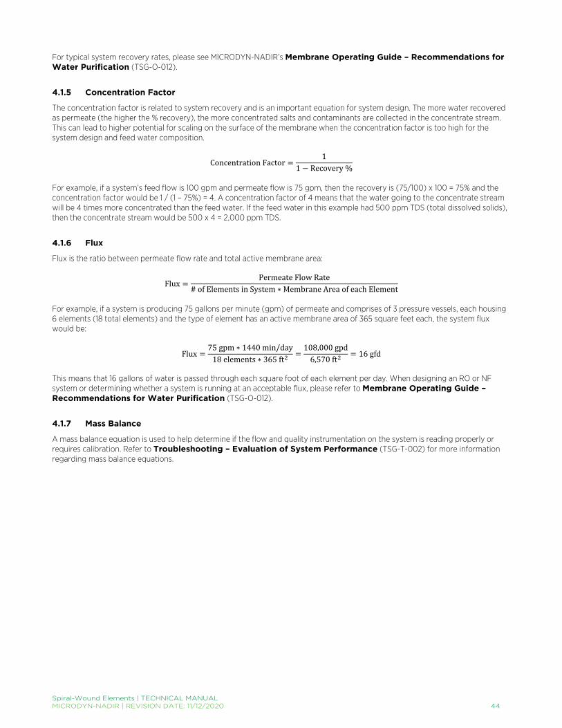
Spiral-Wound Elements | TECHNICAL MANUAL MICRODYN-NADIR | REVISION DATE: 11/12/2020 44
For typical system recovery rates, please see MICRODYN-NADIR’s Membrane Operating Guide – Recommendations for Water Purification (TSG-O-012).
4.1.5 Concentration Factor
The concentration factor is related to system recovery and is an important equation for system design. The more water recovered as permeate (the higher the % recovery), the more concentrated salts and contaminants are collected in the concentrate stream. This can lead to higher potential for scaling on the surface of the membrane when the concentration factor is too high for the system design and feed water composition.
Concentration Factor =1
1 − Recovery %
For example, if a system’s feed flow is 100 gpm and permeate flow is 75 gpm, then the recovery is (75/100) x 100 = 75% and the concentration factor would be 1 / (1 – 75%) = 4. A concentration factor of 4 means that the water going to the concentrate stream will be 4 times more concentrated than the feed water. If the feed water in this example had 500 ppm TDS (total dissolved solids), then the concentrate stream would be 500 x 4 = 2,000 ppm TDS.
4.1.6 Flux
Flux is the ratio between permeate flow rate and total active membrane area:
Flux =Permeate Flow Rate
# of Elements in System ∗ Membrane Area of each Element
For example, if a system is producing 75 gallons per minute (gpm) of permeate and comprises of 3 pressure vessels, each housing 6 elements (18 total elements) and the type of element has an active membrane area of 365 square feet each, the system flux would be:
Flux =75 gpm ∗ 1440 min/day
18 elements ∗ 365 ft2 =108,000 gpd
6,570 ft2 = 16 gfd
This means that 16 gallons of water is passed through each square foot of each element per day. When designing an RO or NF system or determining whether a system is running at an acceptable flux, please refer to Membrane Operating Guide – Recommendations for Water Purification (TSG-O-012).
4.1.7 Mass Balance
A mass balance equation is used to help determine if the flow and quality instrumentation on the system is reading properly or requires calibration. Refer to Troubleshooting – Evaluation of System Performance (TSG-T-002) for more information regarding mass balance equations.

Spiral-Wound Elements | TECHNICAL MANUAL MICRODYN-NADIR | REVISION DATE: 11/12/2020 45
4.1.8 Stages & Passes in System Design
The terms “stage” and “pass” are often mistaken for one another, but it is important to understand the difference between the two. Stages treat the concentrate multiple times whereas passes treat the permeate multiple times. Below are images and descriptions of the two. Stage In a single-stage system, the feed water enters the system as one stream and exits the system as either concentrate or permeate water (Figure 14).
In a two-stage system, the concentrate (or reject) from the first stage becomes the feed water to the second stage (Figure 15). The permeate water collected from the first stage is combined with the permeate water from the second stage. Additional stages increase the overall recovery of the system.
Array In a system, an array describes the physical arrangement of the pressure vessels in a multi-stage system. In a multi-stage system, each stage can have a determined amount of pressure vessels (which typically house 6 elements each). The reject of each stage then becomes the feed stream for the next successive stage. For example, the two-stage system displayed above is a 2:1 array, meaning that the concentrate (or reject) of the first two vessels is fed to the next single vessel.
Feed Water Pressure Vessel
Concentrate
Permeate
Figure 14. A single-stage (and single-pass).
Feed Water
Pressure Vessel Permeate
Pressure Vessel
Concentrate
Permeate
Pressure Vessel
Concentrate
Permeate
Concentrate
1st Stage 2nd Stage
Figure 15. A two-stage system; the concentrate from the first stage becomes the feed to the second stage.

Spiral-Wound Elements | TECHNICAL MANUAL MICRODYN-NADIR | REVISION DATE: 11/12/2020 46
System with Concentrate Recycle If the feed water chemistry and system design allows for it, a concentrate recycle stream can be utilized where a portion of the concentrate stream is fed back to the feed water of the first stage to help increase the system recovery as well as the cross-flow within the pressure vessels (Figure 16).
Single Pass vs. Double Pass System Think of a “pass” as a stand-alone system. As shown in Figure 17, the difference then between a single pass system and a double pass system is that for the latter, the permeate from the first pass becomes the feed water to the second pass (or second stand-alone system). This results in a higher permeate quality because the water has essentially gone through two systems (the water has passed through the membrane twice). Some or all of the second pass concentrate may be recycled back to the feed to increase overall system recovery.
Feed Water
Pressure Vessel Permeate
Pressure Vessel
Concentrate
Permeate
Pressure Vessel Permeate
Concentrate
Concentrate Recycle
Figure 16. A two-stage system with a concentrate recycle stream back to the feed stream.
1st Stage 2nd Stage 1st Stage 2nd Stage
1st Pass 2nd Pass
Figure 17. A two-pass system; the permeate of the first pass becomes the feed to the second pass.

Spiral-Wound Elements | TECHNICAL MANUAL MICRODYN-NADIR | REVISION DATE: 11/12/2020 47
4.2 TEMPERATURE CORRECTION FACTORS: TRISEP® ELEMENTS Permeability of a membrane is partially dependent on feed water temperature. Other factors that may influence membrane permeate flow include driving pressure, osmotic pressure, differential pressure and pH. The dependency of a membrane on temperature will vary between the membrane type and manufacturer. Below are temperature correction factors for TRISEP membranes to estimate the effects of feed water temperature on permeate flow rates by membrane type.
4.2.1 Temperature Correction Equation
To project the estimated effects of temperature alone (all other factors constant) on permeate flow of TRISEP reverse osmosis (RO) membranes, the following equation may be used (the reference temperature is 25°C (77°F)):
TCF = 𝑒𝑒U�1 298� −1 T� � where: TCF = Temperature Correction Factor,
U = 2900 for ACM™, X-20™, XN45 and TS80 membranes, U = 2800 for SB50 and SB20 (cellulose acetate) membranes and T = °C + 273
4.2.2 Temperature Correction Factors by Membrane Type
TABLE 2. TEMPERATURE CORRECTION FACTORS FOR TRISEP MEMBRANES BY MEMBRANE TYPE.
Temperature Temperature Correction Factor by Membrane Type
°C °F SB (cellulose acetate) ACM™, X-20™, XN45 and TS80
1.7 35 0.50 0.44
4.4 40 0.55 0.49
7.2 45 0.60 0.54
10.0 50 0.65 0.60
12.8 55 0.71 0.66
15.6 60 0.77 0.73
18.3 65 0.83 0.80
21.1 70 0.90 0.88
23.9 75 0.97 0.96
26.7 80 1.05 1.06
29.4 85 1.13 1.15
32.2 90 1.21 1.26
35.0 95 1.30 1.37
4.3 TESTING PRIOR TO SYSTEM DESIGN: RO & NF SYSTEMS In water purification applications with a well-pretreated feed, the expected performance of TRISEP® RO & NF membranes can be reasonably projected using MICRODYN-NADIR’s projection software, TROI. However, many situations require various qualification and testing steps prior to the start-up of a full-scale system. Some such situations include: variable or difficult feed quality, process applications, large plant sizes, the presence of organics or silica, and unique or novel applications. Small-scale testing to ensure that the desired separation is achievable at appropriate pressures, membrane flux, and recovery rates is critical to verify the sustainability of full-scale operation, minimize risk, and fine-tune appropriate operating conditions.
4.3.1 Flat Cell Testing
Flat cell testing can be performed in the lab in order to guide the membrane selection process and begin to quantify the rejection and flux properties of the selected membrane with the feed for the project. Coupons cut out of flat sheet membrane are placed in testing cells, and pressurized feed is run through the system in a tangential flow pattern. While this is a quick, inexpensive method to obtain a rough idea of the applicability of a membrane for a separation, this method does not demonstrate long-term usability or fouling effects of the membrane with the feed, nor do the results necessarily translate directly to a scaled-up system.

Spiral-Wound Elements | TECHNICAL MANUAL MICRODYN-NADIR | REVISION DATE: 11/12/2020 48
4.3.2 Lab-Scale Element Testing
Lab-scale element testing is performed in a test system that allows for modifications to the feed pressure, flow, and temperature in order to better understand the membrane performance capabilities under different operating conditions. These systems typically use one 2540 or 4040 size element. Operation of a lab-scale element test system allows for the determination of two important operating conditions: the operating flux and recovery rate. Design flux can be determined by adjusting the feed pressure and flow rate until the desired permeate quality and permeate flux rate are reached. Flux rates for TRISEP® RO & NF membranes are generally between 10 – 35 lmh (6 – 20 gfd), depending on the feed source and application. While determining the flux, the recovery rate should be kept under 15% for a single pass through the membrane system, with the concentrate and permeate both recycled into the feed tank. Once the operating pressure and flux rate are determined they can be used in the next test for determining the recovery rate, as explained below. Recovery rate can be determined by running a batch system at the operating pressure and flux, where the feed line runs to the membrane system, the concentrate line runs back in to the feed tank, and the permeate stream is collected separately. During operation, the permeate quality and the permeate flow should be monitored. Once the permeate quality no longer meets requirements or the permeate flowrate has declined past a reasonable threshold for the project, the testing is ended. Recovery rate and concentration factor can then be calculated using the volumes of feed processed. Recovery rate is equal to the original feed tank volume minus the final feed tank volume, all divided by the original feed tank volume. The concentration factor is simply the original feed tank volume divided by the final feed tank volume.
4.3.3 Pilot Testing
Pilot testing is the most effective testing method used to assess a membrane’s feasibility for a specific feed supply. The goals of piloting can include gathering pretreatment data, determining scaled-up operational characteristics and costs, testing cleaning regimens, ensuring stable operation over time with adequate permeate quality, familiarizing operators with the membrane technology, and demonstrating regulatory compliance. Pilot plants should use at least one 40 inch long element, and the system configuration should mimic that of the scaled system. Pilot systems should run for a minimum of one month, although longer durations allow for a more accurate study of membrane fouling effects. The permeate flow rate of the pilot should be no less than 1% of the scaled system permeate flow rate. One of the most important goals of a pilot plant is studying the fouling effects over time and ensuring that an effective and economic cleaning regimen can be implemented to maintain membrane performance. Cleaning cycles, controls, chemical feed equipment, and post treatment, should all be considered. A site-specific understanding of fouling tendencies is especially necessary for complex feed qualities. 4.4 MEMBRANE SYSTEM COMPONENTS: RO & NF SYSTEMS In order for TRISEP® reverse osmosis & nanofiltration elements to perform safely and efficiently, they must be installed in an appropriate operating environment with the correct components and controls. This guide review the various RO & NF membrane system components common to the membrane filtration industry.
4.4.1 Pretreatment Components
The pretreatment components necessary prior to an RO or NF system are highly site specific, based on the feed water quality. These can include coagulation, sedimentation, media filters, MF/UF membrane filtration, antiscalants, cartridge filters, etc. See Pretreatment – Water Application RO & NF Elements (TSG-C-O11) for an overview of various pretreatment options.
4.4.2 Membrane Skid Frame
Many different membrane skid frame materials are available, including Structural Fiberglass Reinforced Plastic (FRP), Stainless Steel, Steel, and Aluminum. Corrosion resistance is extremely important in order to keep maintenance at a minimum. RO & NF systems are intricate and therefore difficult to coat or paint after installation, so it is critical that corrosion resistant materials are chosen during initial design. The most corrosion resistant frame material is FRP, which requires virtually zero maintenance.
4.4.3 Pressure Vessels
Pressure vessels are available in various different lengths, fitting anywhere from 1 to 8 membrane elements. Material of construction is again critical; fiberglass is the most common and preferred material. Pressure ratings vary by material; fiberglass vessels can generally withstand pressure up to about 83 bar (1,200 psig). The selected pressure vessel should be chosen based on
Spiral-Wound Elements | TECHNICAL MANUAL MICRODYN-NADIR | REVISION DATE: 11/12/2020 49
a pressure rating that accounts for changes in pressure with temperature changes, and allows for increased pressure over time in compensation for fouling. In many systems, normalized operating pressure may increase as much as 15% between cleanings. Pressure vessels are available with either side feed/concentrate ports or end ports. Side ports are more commonly used because they allow vessels to be connected directly together, which reduces piping requirements and the footprint. Note that the static permeate backpressure should never exceed 0.35 bar (5 psi).
4.4.4 Feed Pumps
Multistage centrifugal pumps are the most common choice for the high-pressure feed pumps to a brackish water RO or NF system. Fixed speed motors on centrifugal pumps with throttling valves are common to the membrane industry, although variable frequency drives (VFDs) can be used to minimize power consumption and to control permeate flow. Control systems should be in place to ramp-up to operating pressure smoothly. If there is significant difference in feed temperature during different periods of operation, a VFD should be considered. Most brackish water applications should consider stainless steel for all wetted pump parts.
4.4.5 Valves
Valve selection will be site specific, and heavily depend on the operating pressure of the system. Each RO/NF system will need the following valves: a feed inlet valve, pump throttling valve, pump discharge check valve, permeate line check valve(s), atmospheric drain valve, concentrate line flow control valve, permeate drain valve for start-up and cleanings, and valves for connecting a CIP skid. Butterfly valves are commonly used for the large process valves in the feed, permeate, and concentrate lines. Resilient-seat butterfly valves are typical in low-pressure piping, while high-performance butterfly valves are common to high-pressure piping. Globe or V-Port valves are used for throttling with modulation in high-pressure piping.
4.4.6 Instrumentation & Controls
Installation of the correct process instrumentation is critical for safe membrane operation. All instrumentation should be calibrated to the manufacturer’s specifications, and re-calibrated on a long term schedule. Pressure gauges should be installed on the high-pressure pump inlet and discharge side, the feed, concentrate, and permeate lines, and to measure the pressure drop across the membrane elements in each stage. Pressure switches should initiate shut down for low pump suction or high pump discharge pressure. Pressure relief should be switched on if permeate backpressure exceeds 0.35 bar (5 psi). Flow gauges should be used to monitor the feed, concentrate, and permeate flowrates of each stage, along with the total feed, concentrate, and permeate flowrates. Most membrane systems are ran at constant flows. While magnetic flow meters are preferable to monitor the main process flows, paddlewheel flow meters can be used to save costs in smaller systems or for secondary type flow such as the cleaning flow rate. Conductivity meters should be installed in the feed, concentrate, and permeate line. While, conductivity data can be used to track performance in real-time and schedule cleanings, samples should be taken regularly and analyzed more thoroughly to determine the TDS and constituent ions. pH monitoring is critical in the feed line if acids or antiscalants are being fed to the system. pH meters have a finite lifetime and should be installed in areas with easy access for maintenance and replacement. Oil detection, turbidity control, and oxidation reduction potential monitoring should also take place in the feed line to prevent damage to the membrane elements. Sampling ports should be installed in the feed, concentrate, and permeate lines, as well as in the permeate line directly following each pressure vessel.
4.4.7 CIP System
CIP systems are generally comprised of a cleaning tank, separate pump, cartridge filter, flow meters, and valves. Ports should be installed in the main RO/NF system to allow for easy connection of the CIP skid. For more details on CIP cleaning for RO and NF systems, see Membrane Cleaning Guide – Water Application Elements (TSG-C-O01).

Spiral-Wound Elements | TECHNICAL MANUAL MICRODYN-NADIR | REVISION DATE: 11/12/2020 50
5 System Operation 5.1 LOADING OF PRESSURE VESSELS
5.1.1 Safety Equipment
Having proper equipment is essential for safely executing the following loading procedure. Appropriate gloves, shoes, and safety glasses should be worn at all times. The following additional equipment for installation is recommended:
• Silicone • Glycerin* • Permeate quality water to flush vessel • Sponge/swab, long stick or PVC pipe, and rope to clean vessel • Spare o-rings to replace any damaged o-rings during loading • Shims (please refer to MICRODYN-NADIR’s Element Loading Guide – Shimming Elements (TSG-O-008) for
guidelines) • Instructions and tools recommended by the pressure vessel manufacturer for removing and installing end cap assemblies
*Note: When loading elements into a system, use a silicone based gel or glycerin to lubricate o-rings and brine seals. Do not use oil, grease, or petroleum based compounds as they may cause damage to the membrane or element.
5.1.2 Installation Preparation
1. Check that all items (membrane elements, interconnectors, adapters, and o-rings) are present and in the correct quantities.
2. Carefully remove all dust, dirt, and foreign matter from the pressure vessels before opening them. 3. Disassemble and wash all end cap parts (o-rings, adapters, etc.) with fresh water and keep parts clean for re-installation. 4. Flush permeate or fresh water through the open pressure vessels to remove any dust or debris present in the vessels. If
additional cleaning is necessary, create a sponge/swab large enough to fill the inside diameter of the pressure vessel. Soak the sponge or swab in a 50-75% glycerin/water solution and move it back and forth through the pressure vessel with a piece of rope or long PVC pipe until the vessel is clean and lubricated. Be sure to avoid scraping the inside of the pressure vessel.
5. After cleaning and lubricating the pressure vessel, re-install the concentrate side end cap assemblies of the pressure vessels.
5.1.3 Element Loading
1. Stage the elements prior to loading and record each element’s serial number by position so that each element location within the pressure vessel is known.
2. Open the element bag in a well-ventilated area and remove the element. Refer to the Safety Equipment section and minimize direct contact with the storage solution.
3. Gently place the first element into the feed end of the first pressure vessel and slide the element in approximately one-half to three-quarters of the way. Always load elements into the feed end of the pressure vessel because the brine seal (on fiberglass or tape wrapped elements) makes it difficult to install the element in the opposite direction. Be sure that the U-cup brine seal (if present) is properly seated in the groove of the ATD of the element such that the brine seal opens in the upstream direction.
4. To load elements, lubricate the o-ring seals on the interconnector and the inside of the permeate tube with a thin layer of lubricant and insert the interconnector into the permeate tube of the element. Note: When installing o-rings, expand them slightly, do not roll them into position.
5. If a lubricant is required to ease the loading of elements, apply a thin layer of lubricant to each brine seal to avoid drag. 6. Lift the next element into position and install the previous element into the interconnector to connect elements. Hold the
next element with care so that the weight is not supported by the interconnector, and push the element into the pressure vessel until about one-half of the element extends outside the vessel.
7. Repeat steps 2 through 6 until all elements are loaded into the pressure vessels. 8. After all the elements have been loaded, install the downstream end cap assembly on the end of the pressure vessel.
Carefully position the downstream end cap assembly in the vessel and push the end cap assembly as a unit squarely into the end of the element. Avoid pinching or rolling of the o-rings when seating the o-ring seal on the adapter. Rotate the end cap assembly to ensure proper alignment with the connecting piping.
9. Gently push the element stack from the feed end (upstream) towards the downstream end.

Spiral-Wound Elements | TECHNICAL MANUAL MICRODYN-NADIR | REVISION DATE: 11/12/2020 51
10. After the elements have been installed, determine if it is necessary to add shims before re-installing the upstream end cap. Shims reduce the amount of “freeboard”, or space between the face of the lead element and the face of the adapter hub. Shimming helps prevent elements from moving during system start-up and shutdown. Please refer to Element Loading Guide – Shimming Elements (TSG-O-008) for additional detail.
11. Continue steps 8 through 10 for each pressure vessel in the train or system. 12. Re-install the feed end cap assembly on each of the pressure vessels. Close each pressure vessel with the clean parts
from Step 4 in Installation Preparation above. 5.2 SHIMMING ELEMENTS All pressure vessels are built with some tolerance, known as “freeboard”, to allow for slight variations in the length of elements. During operation, the pressure vessel elongates slightly when pressurized, increasing freeboard. Shimming the elements in a pressure vessel, therefore, helps prevent the elements from sliding back and forth during start-up and shutdown and ensures that the adapters are properly seated in the permeate tubes of the lead and tail elements, preventing leaks. Shims are plastic spacer rings that look like washers. Shims are typically about 5 mm (0.20 inches) thick with an inner diameter slightly larger than the pressure vessel head end of the adapter. Figure 18 shows a diagram of the placement of multiple shims on the feed end adapter between the adapter hub and the pressure vessel head. After fully loaded, the elements should be pushed completely into the vessel such that the downstream element is firmly seated against the thrust ring at the concentrate end of the vessel. The process of shimming is then performed:
1. Remove the adapter o-ring and head seal from the feed end cap assembly. 2. Remove the adapter from the head assembly and gently lubricate the adapter seal with lubricant (see approved
lubricants in Element Loading Guide – Loading of Pressure Vessels (TSG-O-006)). 3. Insert the adapter into the element permeate tube. 4. Remove the end cap on the adapter and slide shims over adapter. Add enough spacers so it is not possible to install the
retaining rings after seating the head. 5. Remove one spacer at a time until you can just install the retaining rings. The slight remaining movement, or a gap of ~2
mm between the end plate and the shims, is acceptable and will not cause problems in performance. 6. Insert the adapter into the end cap permeate port and re-install o-rings, lubricating them gently with lubricant. 7. Install the end cap assembly. Lubricate as necessary. 8. Close the vessel. 9. Repeat steps 1 through 8 for all pressure vessels.
5.3 START-UP The following is intended to provide information on system start-up with TRISEP®, SPIRA-CEL® and MICRODYN RO elements.
5.3.1 System Start-Up
Safety Equipment Having proper equipment is essential for safely executing the following start-up procedure. Appropriate gloves, shoes and safety glasses should be worn at all times. Additional equipment may be necessary depending on specific system design. Mechanical Inspection A mechanical inspection of the system is recommended prior to start-up. This inspection should ensure that valves are positioned correctly, lines are free of air, safety precautions are functioning, instrumentation is calibrated, pumps are lubricated and have proper rotation and all pretreatment is operating properly.
Figure 18. Placement of shims on the adapter between the element and pressure vessel.
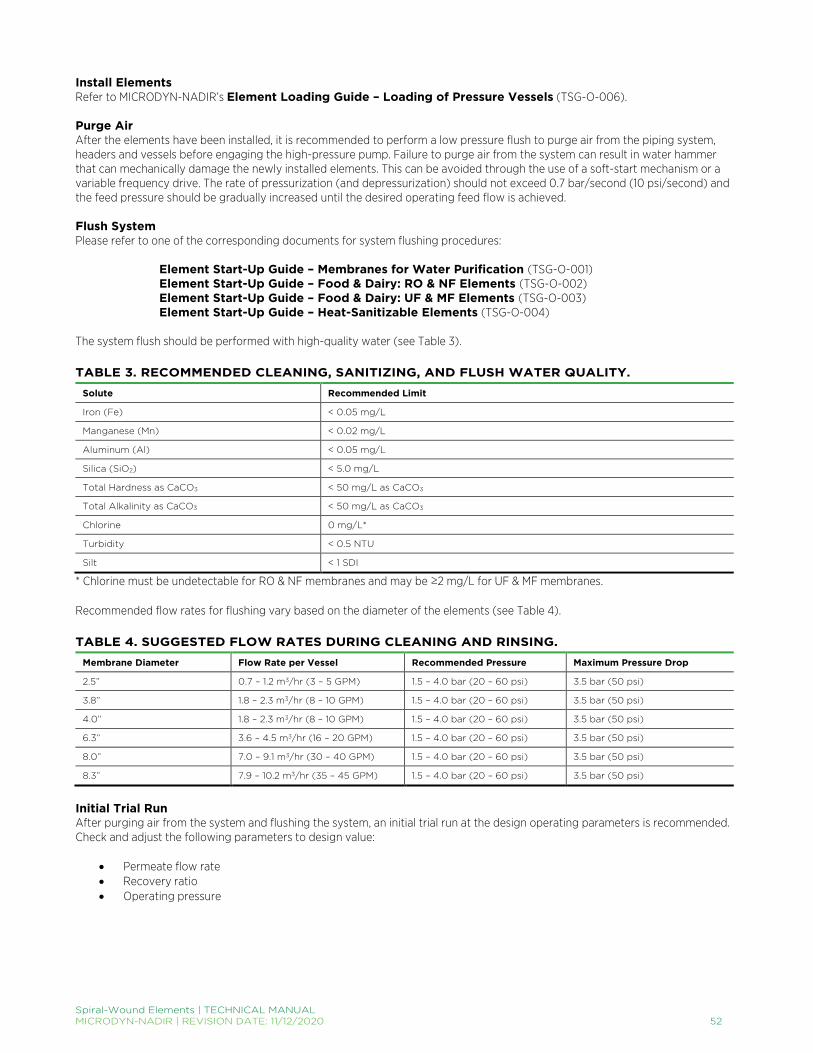
Spiral-Wound Elements | TECHNICAL MANUAL MICRODYN-NADIR | REVISION DATE: 11/12/2020 52
Install Elements Refer to MICRODYN-NADIR’s Element Loading Guide – Loading of Pressure Vessels (TSG-O-006). Purge Air After the elements have been installed, it is recommended to perform a low pressure flush to purge air from the piping system, headers and vessels before engaging the high-pressure pump. Failure to purge air from the system can result in water hammer that can mechanically damage the newly installed elements. This can be avoided through the use of a soft-start mechanism or a variable frequency drive. The rate of pressurization (and depressurization) should not exceed 0.7 bar/second (10 psi/second) and the feed pressure should be gradually increased until the desired operating feed flow is achieved. Flush System Please refer to one of the corresponding documents for system flushing procedures:
Element Start-Up Guide – Membranes for Water Purification (TSG-O-001) Element Start-Up Guide – Food & Dairy: RO & NF Elements (TSG-O-002) Element Start-Up Guide – Food & Dairy: UF & MF Elements (TSG-O-003) Element Start-Up Guide – Heat-Sanitizable Elements (TSG-O-004)
The system flush should be performed with high-quality water (see Table 3). TABLE 3. RECOMMENDED CLEANING, SANITIZING, AND FLUSH WATER QUALITY.
Solute Recommended Limit
Iron (Fe) < 0.05 mg/L
Manganese (Mn) < 0.02 mg/L
Aluminum (Al) < 0.05 mg/L
Silica (SiO2) < 5.0 mg/L
Total Hardness as CaCO3 < 50 mg/L as CaCO3
Total Alkalinity as CaCO3 < 50 mg/L as CaCO3
Chlorine 0 mg/L*
Turbidity < 0.5 NTU
Silt < 1 SDI
* Chlorine must be undetectable for RO & NF membranes and may be ≥2 mg/L for UF & MF membranes. Recommended flow rates for flushing vary based on the diameter of the elements (see Table 4). TABLE 4. SUGGESTED FLOW RATES DURING CLEANING AND RINSING.
Membrane Diameter Flow Rate per Vessel Recommended Pressure Maximum Pressure Drop
2.5” 0.7 – 1.2 m3/hr (3 – 5 GPM) 1.5 – 4.0 bar (20 – 60 psi) 3.5 bar (50 psi)
3.8” 1.8 – 2.3 m3/hr (8 – 10 GPM) 1.5 – 4.0 bar (20 – 60 psi) 3.5 bar (50 psi)
4.0” 1.8 – 2.3 m3/hr (8 – 10 GPM) 1.5 – 4.0 bar (20 – 60 psi) 3.5 bar (50 psi)
6.3” 3.6 – 4.5 m3/hr (16 – 20 GPM) 1.5 – 4.0 bar (20 – 60 psi) 3.5 bar (50 psi)
8.0” 7.0 – 9.1 m3/hr (30 – 40 GPM) 1.5 – 4.0 bar (20 – 60 psi) 3.5 bar (50 psi)
8.3” 7.9 – 10.2 m3/hr (35 – 45 GPM) 1.5 – 4.0 bar (20 – 60 psi) 3.5 bar (50 psi)
Initial Trial Run After purging air from the system and flushing the system, an initial trial run at the design operating parameters is recommended. Check and adjust the following parameters to design value:
• Permeate flow rate • Recovery ratio • Operating pressure

Spiral-Wound Elements | TECHNICAL MANUAL MICRODYN-NADIR | REVISION DATE: 11/12/2020 53
Prior to final evaluation of the trial run, operate the system for a minimum of two hours at the design operating conditions. All permeate and concentrate produced during the trial run should be discarded to drain. Product Quality Check the quality of the product and system performance as following:
• Check product quality for each vessel. If the product quality does not meet specification, check o-rings and brine seals of the affected vessel. Log all data and corrective measures taken within the first 24 – 48 hours. Although membrane performance should stabilize after the first couple hours of operation, monitoring feed pressure, differential pressure, flows, recovery, and product quality will help indicate if the elements are performing as expected. This data may be used to normalize and track system performance.
• Recommended data to be logged: o Feed: feed pressure, temperature, feed quality (i.e. TDS or conductivity), pH o Differential pressure across each vessel o Concentrate: flow, concentrate quality, pH o Permeate: flow and permeate quality of each vessel and total system.
• It is also recommended to take water samples for analysis for individual ions and to compare operation results with projected data.
5.3.2 Heat-Sanitizable Element Start-Up Procedure
After the elements have been removed from their packaging and have been installed into their pressure vessels (please refer to Element Loading Guide – Loading of Pressure Vessels (TSG-O-006) for loading instructions), the following heat-setting procedure must be performed prior to initial use of elements. The procedure below will remove residual storage solution and will prepare membranes for start-up (Table 5). This same procedure may also be used for subsequent heat-sanitizations. Heat-sanitizable RO and NF elements will have high water permeability before being exposed to the initial heat-setting procedure. After the initial heat-setting, the elements will experience a one-time flux loss and attain the specified flow and salt rejection performance characteristics listed on the product data sheet. The performance will remain stable despite subsequent additional heat-sanitization cycles. TABLE 5. HEAT-SETTING PROCEDURE FOR TRISEP HEAT-SANITIZABLE RO, NF, UF, AND MF ELEMENTS FOR HIGH PURITY APPLICATIONS.
Step Procedure
1 Flush system with high quality water to drain for 30 min at low pressure and low permeate flow rate (see Tables 3 & 4).
2 Recirculate near-neutral (pH 6 – 8) water through the system at a pressure not exceeding 1.7 bar (25 psi). Maximum pressure drop through a single element is 0.5 bar (7.3 psi).
3 Ramp temperature up at a rate no faster than 5°C/min until a temperature between 80 – 90°C (176 – 194°F) for one hour.
4 Maintain temperature between 80 – 90°C (176 – 194°F) for one hour.
5 Ramp temperature down at a rate no faster than 5°C/min until a temperature below 45°C (113°F) is achieved.
6 Flush system with high quality water to drain at very low pressure (Table 3).
Note: DO NOT recycle permeate during the heat-setting procedure. Note: DO NOT start-up a second pass RO before the first pass RO has been heat-set.

Spiral-Wound Elements | TECHNICAL MANUAL MICRODYN-NADIR | REVISION DATE: 11/12/2020 54
5.3.3 RO & NF Process Element Start-Up Procedure
After the elements have been removed from their packaging and have been installed into their pressure vessels (please refer to Element Loading Guide – Loading of Pressure Vessels (TSG-O-006) for loading instructions), a cleaning procedure must be performed prior to initial use of elements per FDA regulation. According to the Code of Federal Regulations (CFR) Title 21 Section 177.2550, “to assure their safe use, reverse osmosis membranes and their supports shall be thoroughly cleaned prior to their first use in accordance with current good manufacturing practice.” The cleaning procedure below meets 21 CFR Section 177.2550 specifications and prepares membranes for start-up (Table 6). TABLE 6. START-UP CLEANING PROCEDURE FOR TRISEP® RO & NF ELEMENTS USED IN PROCESS APPLICATIONS.
Step Cycle pH Temperature Duration (min) Procedure
1 Flush Neutral 30 – 40°C (86 – 104°F) 10
Flush system with high quality water (see Tables 2 & 3) using a minimum of three times the system hold-up volume, sending concentrate and permeate to drain.
2 Alkaline 10.0 – 10.5 30 – 40°C (86 – 104°F) 20
Add high pH cleaner or sodium hydroxide to adjust pH. Circulate alkaline solution at standard pressure and flow conditions as shown in Table 3 for 20 minutes.
3 Flush Neutral 30 – 40°C (86 – 104°F) 10
Flush system with high quality water using a minimum of three times the system hold-up volume, sending concentrate and permeate to drain.
5.3.4 UF & MF Process Element Start-Up Procedure
After the elements have been removed from their packaging and have been installed into their pressure vessels (please refer to Element Loading Guide – Loading of Pressure Vessels (TSG-O-006) for loading instructions), the following cleaning procedure must be performed prior to initial use of elements. According to the Code of Federal Regulations (CFR) Title 21 Section 177.2550, dairy elements should be thoroughly cleaned prior to their first use in accordance with current good manufacturing practice. The cleaning procedure below meets 21 CFR Section 177.2550 specifications and prepares membranes for start-up (Table 7). TABLE 7. START-UP CLEANING PROCEDURE FOR TRISEP AND SPIRA-CEL UF & MF ELEMENTS USED IN FOOD & DAIRY APPLICATIONS.
Step Cycle pH Temperature Duration (min) Procedure
1 Flush Neutral 30 – 40°C (86 – 104°F) 10
Flush system with high quality water (see Table 2) using a minimum of three times the system hold-up volume, sending concentrate and permeate to drain.
2 Alkaline / Chlorine 10.5 – 11.0 30 – 40°C (86 – 104°F) 15
Add high pH cleaner to adjust pH and then add 180-200 ppm total chlorine.* Circulate solution at standard pressure and flow conditions listed in Table 3 for 15 minutes. *Note: Do not add chlorine until the pH has been adjusted to at least 10.5.
3 Flush Neutral 30 – 40°C (86 – 104°F) 10
Flush system with high quality water using a minimum of three times the system hold-up volume, sending concentrate and permeate to drain.
5.3.5 Water Purification Element Start-Up Procedure
After the elements have been removed from their packaging and installed into their pressure vessels (please refer to Element Loading Guide – Loading of Pressure Vessels (TSG-O-006) for loading instructions), it is important to flush out any residual storage solution before start-up. This flush also ensures that any other contaminants existing in the system are removed. The system flush should be performed with high-quality water (see Table 3). The recommended flow rates for flushing vary based on the diameter of the elements (see Table 4). Generally, flushing for 30 minutes is sufficient to prepare elements for operation. All fluid produced during the system flush should be discarded to a drain.

Spiral-Wound Elements | TECHNICAL MANUAL MICRODYN-NADIR | REVISION DATE: 11/12/2020 55
5.4 OPERATING CONDITIONS FOR WATER PURIFICATION ELEMENTS The following are operating recommendations for TRISEP® and MICRODYN RO spiral-wound elements used in water purification. It is the user’s responsibility to determine the appropriateness of TRISEP, SPIRA-CEL® and MICRODYN RO products for the user’s specific end uses. For questions or additional information, please contact MICRODYN-NADIR Technical Service.
5.4.1 Biological Matter
Biological activity inside the element must be controlled during operation so that system water quality and quantity are not affected.
5.4.2 Chlorine / Bromine
• MICRODYN-NADIR recommends that the total free chlorine and bromine content of water entering thin-film composite element(s) be non-detectable.
• Total free chlorine tolerance for TRISEP thin-film composite membranes is in the range of 1000 – 2000 ppm-hrs, when exposed at concentrations less than 1 ppm.
• The total free chlorine and bromine content of all water entering cellulose acetate (CA), polyethersulfone (PES) and polyvinylidene fluoride (PVDF) ultrafiltration (UF) and microfiltration (MF) element(s) is recommended to be <1.0 mg/L.
• The presence of iron and other transition metals, such as ferric hydroxide, may reduce the oxidation tolerance substantially of all membranes. Elevated temperatures will also reduce the oxidation tolerance of all membranes.
5.4.3 Miscellaneous Chemicals
• Prevent chemicals which form a water-immiscible phase in the feed or concentrate from entering the element. • Avoid use of cationic, anionic, or non-ionic polyelectrolytic compounds in elements. • Keep all water entering the element free of strong oxidants such as O3 and KMnO4. • Use caution when using hydrogen peroxide/peracetic acid sanitization solutions. Refer to Membrane Disinfection
Guide – Hydrogen Peroxide/Peracetic Acid Mixtures (TSG-C-006) and consult the cleaning chemical supplier’s instructions.
• Be sure that impurities present in chemicals added to the feed water do not affect element performance. • Membrane damage caused by chemical compounds (e.g. surfactants, solvents, soluble oils, free oils, lipids, and high
molecular weight natural polymers) shall nullify and void the warranty. Use with caution.
5.4.4 Solubility Limits
• The Langelier Saturation Index (LSI) of the brackish water concentrate stream should be negative to prevent scaling. • The LSI may be positive if an antiscalant is being used to combat scaling. When an antiscalant is used, flushing the system
within 15 minutes after shutdown is recommended to remove the supersaturated salt solutions.
5.4.5 Suspended Solids
The recommended feed turbidity is <1.0 NTU for all elements. Operation at turbidities higher than 1.0 NTU may require more frequent membrane cleanings and may reduce membrane life.
5.4.6 Silt Density Index
The Silt Density Index (SDI) value of the feed water entering a system correlates fairly well with the amount of fouling material present. Table 8 below lists recommended SDI values for different feed waters.
5.4.7 System Design: Target Flux
The fouling tendency of the feed water has the greatest influence on system design. Membrane fouling is caused by particles and colloidal material present in the feed water and are concentrated at the membrane surface. Fouling increases at the membrane surface with increasing flux (permeate flow rate per unit membrane area) and increasing element recovery (ratio of permeate flow rate to feed flow rate for a single element). Higher flux rates could lead to higher fouling rates and more frequent chemical cleanings.

Spiral-Wound Elements | TECHNICAL MANUAL MICRODYN-NADIR | REVISION DATE: 11/12/2020 56
A membrane system should be designed such that each element of the system operates within a frame of recommended operating conditions to minimize the fouling rate and to avoid mechanical damage. These element operating conditions are limited by the maximum recovery, maximum permeate flow rate, minimum concentrate flow rate and the maximum feed flow rate per element. The higher the fouling tendency of the feed water, the stricter the limits of these parameters become. The target flux of a system is a useful number to quickly estimate the required number of elements for a project. Systems operating on high quality feed waters are typically designed at high flux values whereas systems operating on poor quality feed waters are designed at low flux values. However, systems can be designed with higher or lower flux values depending on capital or operational expenses. A continuous process designed around these considerations will show stable performance with no more than about four cleanings per year in standard applications. Exceeding the recommended limits may result in more frequent cleanings, reduced capacity, increased feed pressure and reduced membrane life. Table 8 lists the typical ranges of flux values for the majority of systems. TABLE 8. DESIGN RECOMMENDATIONS FOR RO AND NF ELEMENTS.
Feed Source RO Permeate Well Water Softened Municipal Surface Wastewater (filtered tertiary effluent)
Feed Silt Density Index (SDI) < 1 < 3 < 3 < 5 < 3
Typical Target Flux Lmh (gfd) 37 (22) 26 – 31 (15 – 18) 27 – 31 (16 – 18) 20 – 24 (12 – 14) 17 – 22 (10 – 13)
Maximum Element Recovery % 30 19 17 15 14
5.4.8 Operating Conditions: Flow Rates
• TRISEP®, SPIRA-CEL® and MICRODYN RO product specification sheets list the permeate flows (m3/day and gpd) for each element, however Table 9 lists the recommended flow rates per pressure vessel for 4, 8, and 8.5 inch diameter elements:
TABLE 9. RECOMMENDED FLOW RATES PER PRESSURE VESSEL FOR 4”, 8”, AND 8.5” ELEMENTS.
Model Minimum Concentrate m3/h (gpm) Maximum Feed m3/h (gpm)
4” 1.1 (50) 4.5 (20.0)
8” 4.5 (20.0) 18.2 (80.0)
8.5” 4.5 (20.0) 19.3 (85.0)
• For cleaner streams, systems may be successfully operated at lower concentrate flow. For streams that are more prone
to fouling or scaling, systems may be successfully operated at higher concentrate flow.
5.4.9 Operating Conditions
Although the MICRODYN-NADIR product specification sheets list the maximum operating pressures and temperatures, it is recommended to keep the following in mind when operating a membrane system:
• The product pressure must never exceed the feed or concentrate pressure. • For operation outside the limits listed on the product specification sheet, consult MICRODYN-NADIR.

Spiral-Wound Elements | TECHNICAL MANUAL MICRODYN-NADIR | REVISION DATE: 11/12/2020 57
5.4.10 Flushing
• Flush water must be of good quality and of low TDS (<2000 ppm). See Table 10 below. • The product side must be open to atmosphere when flushing or adding water to the element. • When scale inhibitor is used, the element must be flushed at shutdown within 15 minutes to remove antiscalant and the
supersaturated salt solution. TABLE 10. FLUSH WATER QUALITY RECOMMENDATIONS.
Solute Recommended Limit
Iron (Fe) < 0.05 mg/L
Manganese (Mn) < 0.02 mg/L
Aluminum (Al) < 0.05 mg/L
Silica (SiO2) < 5.0 mg/L
Total Hardness as CaCO3 < 50 mg/L as CaCO3
Total Alkalinity as CaCO3 < 50 mg/L as CaCO3
Chlorine 0 mg/L*
Turbidity < 0.5 NTU
Silt < 1 SDI
* Chlorine must be undectable for RO & NF membranes and may be ≥2 mg/L for UF & MF membranes. 5.5 SYSTEM SHUTDOWN
5.5.1 Safety Equipment
Having proper equipment is essential for safely executing the following shutdown procedure. Appropriate gloves, shoes and safety glasses should be worn at all times. Additional equipment may be necessary depending on specific system design.
5.5.2 Shutting Down Procedure
1. Ensure that all chemical injections used for pretreatment have been stopped. 2. Flush the system at low pressure with permeate quality water (see Table 10) to remove high salt concentration from the
pressure vessels and until the concentrate conductivity matches the feed water conductivity. 3. After flushing the system, make sure all feed valves are completely closed. 4. If the concentrate line ends into a drain below the level of the pressure vessels, employ an air break in the concentrate
line at a position higher than the highest pressure vessel to prevent a siphoning effect. 5. If the permeate line is pressurized during operation and the system is shut down, the membrane might become exposed
to a static permeate backpressure, which may damage the membrane and void the warranty. Check valves or atmospheric drain valves in the permeate line can be used.
6. When the system is shut down for longer than 48 hours, be sure that the elements do not dry out. Dry elements will irreversibly lose flux. Please refer to MICRODYN-NADIR’s Element Storage Guide – Storage for Offline Elements (TSG-O-009).
5.6 STORAGE
5.6.1 Storage of Flat Sheet Membrane
Dry Membrane Most TRISEP® and NADIR® flat sheet membrane is shipped dry. Dry membrane is bagged and sealed in a plastic bag and does not require any preservation solution. It is recommended to keep the dry membrane in its sealed bag until its intended use. For storage of dry flat sheet membrane, the following steps are recommended:
• Store membrane inside a cool building or warehouse and not in direct sunlight. • TRISEP temperature limits for storage: -4°C to 35°C (22°F to 95°F). • NADIR temperature limits for storage: 5°C to 30°C (41°F to 86°F ). • All new membrane being stored prior to use should remain in its original packaging.

Spiral-Wound Elements | TECHNICAL MANUAL MICRODYN-NADIR | REVISION DATE: 11/12/2020 58
Wet Membrane Some TRISEP flat sheet membrane is supplied wet, in a rolled format for shipment.
• Membranes must be kept away from direct sunlight and are best kept refrigerated at 4°C to 7°C (40°F to 45°F). This prevents biological growth and oxidation of the residual organic amines in the membrane.
• If membrane is kept in refrigerated storage, it should be used within 60-90 days of receipt. If membrane is not kept in refrigerated storage, it should be used within 30 days to avoid biological growth.
Handling Flat Sheet Membrane When handling TRISEP and NADIR flat sheet, use butyl or nitrile gloves to prevent contact with residual organic amines as well as preventing oil from hands coming into contact with the membrane. IMPORTANT: The first one to two (1 – 2) wraps of membrane may be damaged in shipment and should be inspected for damage or discarded.
5.6.2 Storage for Offline Elements
Short-Term Storage For short-term storage of membrane elements in place within a water treatment system, the elements should be cleaned and then flushed daily with high-quality water. The following steps to minimize biogrowth or scale formation are recommended:
1. When taking the membrane system offline, it is suggested that a full cleaning and flush of the system be performed. High-quality water is recommended for both cleaning and flush water.
2. During the storage period, it is recommended that the membrane system be flushed once daily with RO quality water to maintain an environment free from biological growth, oxidants and sparingly soluble salts that may scale the membrane.
3. Precautions should be taken to prevent exposing membranes to permeate backpressure when the high pressure pump is turned off (especially in cases where the permeate line is pressurized).
4. Precautions should also be taken to ensure the elements remain wet and are protected from temperature extremes during the shut-down period.
Long-Term Storage If the system is not to be operated for over 5 days, long-term storage is recommended. For long-term storage of the membrane elements in place within a system, it is recommended that the elements be cleaned and then preserved using a solution of sodium metabisulfite. The following steps are recommended:
1. When taking the membrane system offline, it is suggested that a full cleaning and flush of the system be performed. High-quality water meeting the recommended flush water quality should be used for both cleaning and flushing.
2. During the storage period, it is recommended that the membrane system be preserved using a 1% food-grade sodium metabisulfite (SMBS) solution to inhibit microbial growth. The SMBS solution should be recirculated through the membrane system for 30-60 minutes.
3. Vent air from the system and recirculate in a manner to minimize air in the system as oxygen will cause the SMBS to oxidize, dropping the pH and increasing the potential for microbial growth.
4. Following preservation, the feed, permeate and concentrate valves should be closed to isolate the system. During the storage period, the system should be periodically checked to insure that pH does not drop below 3. The recommended frequency of checks is every 30 days. If the pH should drop below 3 during storage, or if the preservative solution becomes discolored, the system should be flushed and the preservation process should be repeated.
5. Precautions should be taken to prevent exposing membranes to permeate backpressure when the high pressure pump is turned off (especially in cases where the permeate line is pressurized).
6. Precautions should also be taken to ensure the elements remain wet and protected from temperature extremes during the shut-down period.
7. When returning the membrane system to service, the preserved elements should be flushed to remove the SMBS solution prior to restart. Permeate from the first hour of operation should be discarded.

Spiral-Wound Elements | TECHNICAL MANUAL MICRODYN-NADIR | REVISION DATE: 11/12/2020 59
5.6.3 Storage & Re-wetting
Element Storage TRISEP®, SPIRA-CEL® and MICRODYN RO elements have a warrantable shelf life of one year. Wet elements will maintain their flux/rejection characteristics for a minimum of 12 months upon arrival, while dry elements will maintain their flux/rejection characteristics for a minimum of 2 years upon arrival if stored in optimum conditions. The following are general guidelines for storage of TRISEP, SPIRA-CEL and MICRODYN RO elements:
• Store elements inside a cool building or warehouse and not in direct sunlight. • TRISEP and MICRODYN RO temperature limits for storage: -4°C to 35°C (22°F to 95°F). Elements are stored in a
preservative solution which may freeze in cold weather; however they will not be damaged. If freezing occurs, thaw the elements before loading.
• SPIRA-CEL and TRISEP DS temperature limits for storage: 5°C to 30°C (41°F to 86°F). Elements may not be exposed to freezing conditions.
• All new elements being stored prior to use should remain in their original packaging. Dry elements are vacuum sealed in a plastic bag, whereas wet elements are packaged in a storage solution that both protects the membrane’s performance and prevents biological growth.
• Wet elements that have been removed from their packaging should be re-bagged with a storage solution to prevent the elements from drying out and to maintain a sterile storage environment.
Re-wetting of Dried Out Membranes Elements that have dried out after use may irreversibly lose water permeability. Although there aren’t many published re-wetting procedures, customers have reported successful methods. Re-wetting may be successful with one of the following:
• Soak the elements in an alcohol solution. Though safety precautions should be taken, methanol may be most effective. • Pressurize the element with the permeate port nearly closed.

Spiral-Wound Elements | TECHNICAL MANUAL MICRODYN-NADIR | REVISION DATE: 11/12/2020 60
6 Cleaning & Sanitization During operation, the surface of a membrane is subject to fouling by mineral scale, biological matter, colloidal particles, and insoluble organic constituents. The term “fouling” includes the build-up of any type of material on the membrane surface, including mineral scaling. Membrane surface fouling results in lower permeate flow rate, increased pressure drop between the feed and concentrate, and/or higher solute passage. Safety Precautions When using the chemicals indicated below, please follow these accepted safety practices:
1. Always wear eye protection. In the case of handling corrosive chemicals, wear full-face masks and protective clothing. Consult the chemical manufacturer for detailed information about safety, handling, and disposal.
2. When preparing cleaning solutions, ensure that all chemicals are dissolved and well mixed before circulating the solutions to the elements.
3. High-quality water must be used for flushing, cleaning, and disinfecting TRISEP® and NADIR® membranes. See Water Quality for Membrane Cleaning & Disinfecting (Table 11).
4. Cleaning chemicals will be present on both the permeate and concentrate sides of the membrane immediately after cleaning. Properly flush the system prior to operation with the feed stream and divert permeate to drain for at least 30 minutes or until the water is clear when starting up after cleaning.
Water Quality for Membrane Cleaning & Disinfecting The quality of water used for CIP is important in order to avoid unwanted deposits on the membrane. RO quality water is recommended for flushing, cleaning, and disinfecting of TRISEP and NADIR membranes, but prefiltered water may be used. Table 11 outlines the quality of water suitable for the above cleaning procedure. TABLE 11. CLEANING & DISINFECTING WATER QUALITY RECOMMENDATIONS.
Solute Recommended Limit
Iron (Fe) < 0.05 mg/L
Manganese (Mn) < 0.02 mg/L
Aluminum (Al) < 0.05 mg/L
Silica (SiO2) < 5.0 mg/L
Total Hardness as CaCO3 < 50 mg/L as CaCO3
Total Alkalinity as CaCO3 < 50 mg/L as CaCO3
Chlorine 0 mg/L*
Turbidity < 0.5 NTU
Silt < 1 SDI
* Chlorine must be undectable for RO & NF membranes and may be ≥2 mg/L for UF & MF membranes. Flow Rates High fluid flow rates improve the effectiveness of cleanings by flushing foulants removed during the process from the membrane system. Recommended flow rates vary based on the diameter of the membrane elements being cleaned. Table 12 summarizes the recommended flow rates and cleaning pressures. Please note that pressure drop during cleaning should not be allowed to exceed 3.5 bar (50 psi) across a pressure vessel or 1.0 bar (15 psi) per installed element within a vessel. TABLE 12. RECOMMENDED FLOW RATES FOR FLUSHING, CLEANING & RINSING.
Membrane Diameter Flow Rate per Vessel Recommended Pressure Maximum Pressure Drop
2.5” 0.7 – 1.2 m3/hr (3 – 5 GPM) 1.5 – 4.0 bar (20 – 60 psi) 3.5 bar (50 psi)
3.8” 1.8 – 2.3 m3/hr (8 – 10 GPM) 1.5 – 4.0 bar (20 – 60 psi) 3.5 bar (50 psi)
4.0” 1.8 – 2.3 m3/hr (8 – 10 GPM) 1.5 – 4.0 bar (20 – 60 psi) 3.5 bar (50 psi)
6.3” 3.6 – 4.5 m3/hr (16 – 20 GPM) 1.5 – 4.0 bar (20 – 60 psi) 3.5 bar (50 psi)
8.0” 7.0 – 9.1 m3/hr (30 – 40 GPM) 1.5 – 4.0 bar (20 – 60 psi) 3.5 bar (50 psi)
8.3” 7.9 – 10.2 m3/hr (35 – 45 GPM) 1.5 – 4.0 bar (20 – 60 psi) 3.5 bar (50 psi)
8.5” 7.9 – 10.2 m3/hr (35 – 45 GPM) 1.5 – 4.0 bar (20 – 60 psi) 3.5 bar (50 psi)

Spiral-Wound Elements | TECHNICAL MANUAL MICRODYN-NADIR | REVISION DATE: 11/12/2020 61
A low flow rate should be used for the pre-soak recirculation. This flow rate would be about 50% less of what is shown in Table 12. A high flow rate should be used for the post-soak recirculation. This flow rate would be about 50% more of what is shown in Table 12. For extended soaks (10 – 15 hours), a very low flow may be used to maintain consistent temperature and pH throughout the duration of the soak. This flow rate would be about 10% of what is shown in Table 12. 6.1 RO & NF PROCESS ELEMENT CLEANING & SANITIZATION The following are general recommendations for cleaning sanitary TurboClean® and TRISEP® reverse osmosis (RO) and nanofiltration (NF) elements in process and specialty applications. More detailed procedures for cleaning membrane systems in process applications should be provided by the system supplier or the cleaning chemical supplier.
6.1.1 Cleaning Precautions
Certain chemicals and cleaning conditions may have an adverse effect on membrane performance. We recommend caution with the following:
• Aggressive alkaline cleanings at high temperature and pH may cause membrane degradation and lead to premature failure. Please follow the recommendations of the system supplier or the cleaning chemical supplier.
• Nitric acid solutions may have an oxidizing effect on the membranes, especially on nanofiltration, and therefore should be used with caution.
• Frequent disinfection with an oxidizing solution (such as hydrogen peroxide blend) more than 1-2 times per week may cause premature membrane oxidation.
6.1.2 Cleaning Method
The cleaning method described below is meant to be a general procedure. Between each step the system must be flushed with high-quality water; please refer to Water Quality below for specific requirements.
1. Shut down the system to be cleaned. Be sure to follow all safety procedures for system shutdown. 2. Purge feed stream from the system. 3. Flush system with water. See Water Quality for Membrane Cleaning & Disinfecting (Table 11) for specific requirements. 4. Alkaline wash, maximum of pH 12.0, maximum of 50°C (122°F), 30 minutes. 5. Flush system with water. 6. Acid wash, pH 2.0, maximum of 50°C (122°F), 30 minutes. 7. Flush system with water. 8. Enzyme wash, pH 9.5, maximum of 50°C (122°F), 45 minutes. 9. Flush system with water. 10. Clean water flux readings (see Checking Cleaning Effectiveness below). 11. Chemical soak, pH 3.6, no heat, 15 minutes if duration between production and CIP is over 2 hours.* 12. Flush system with water.
*Once per week, substitute a chemical sanitization with a hydrogen peroxide/peracetic acid blend (about 350 ppm active ingredient) at 20°C (68°F) for 15 minutes.
6.1.3 Disinfection
In many food & dairy plants, cleaning is followed by a chemical disinfection. The frequency of disinfections is based on plant need, feed quality and membrane type. The procedure for a chemical disinfection is similar to the cleaning procedure (i.e. dosing and circulating the solution prior to flushing the system with water). It is important that chemical disinfection using peroxide be done only at or below 25°C (77°F) and in acidic conditions. It is also critical that all iron is removed from the membrane surface prior to disinfection. For more information, please refer to MICRODYN-NADIR’s Membrane Disinfection Guide – Hydrogen Peroxide/Peracetic Acid Mixtures (TSG-C-006).

Spiral-Wound Elements | TECHNICAL MANUAL MICRODYN-NADIR | REVISION DATE: 11/12/2020 62
6.2 UF & MF PROCESS ELEMENT CLEANING & SANITIZATION The following are general recommendations for cleaning sanitary TurboClean® and TRISEP® ultrafiltration (UF) and microfiltration (MF) membranes with polyester backing in food & dairy applications. More detailed procedures for cleaning membrane systems in process applications should be provided by the system supplier or the cleaning chemical supplier. For pHT cleaning recommendations, please refer to the Membrane Cleaning Guide – Food & Dairy: pHT Elements (TSG-C-007).
6.2.1 Cleaning Precautions
Certain chemicals and cleaning conditions may have an adverse effect on membrane performance. We recommend caution with the following:
• Aggressive alkaline cleanings at high temperature and pH may cause membrane degradation and lead to premature failure. Please follow the recommendations of the system supplier or the cleaning chemical supplier.
• Before adding chlorine, be sure that the pH has been adjusted to at least 10.5.
6.2.2 Cleaning Method
The cleaning method described below is meant to be a general procedure. Between each step the system must be flushed with high-quality water; please refer to Water Quality below for specific requirements.
1. Shut down the system to be cleaned. Be sure to follow all safety procedures for system shutdown. 2. Purge feed stream from the system. 3. Flush system with water. See Water Quality for Membrane Cleaning & Disinfecting (Table 11) for specific requirements. 4. Alkaline wash with 180 ppm chlorine*, maximum of pH 11.5, maximum of 55°C (131°F) for TurboClean elements or 50°C
(122°F) for TRISEP® DS elements, 30 minutes. *Note: Do not add chlorine until the pH has been adjusted to at least 10.5.
5. Flush system with water. 6. Enzyme wash, pH 9.5, maximum of 55°C (131°F) for TurboClean elements or 50°C (122°F) for TRISEP DS elements, 45
minutes. 7. Flush system with water. 8. Acid wash, pH 2.0, maximum of 55°C (131°F) for TurboClean elements or 50°C (122°F), 30 minutes. 9. Flush system with water. 10. Alkaline wash with 180 ppm chlorine*, maximum of pH 11.5, maximum of 55° (131°F) for TurboClean elements or 50°C
(122°F) for TRISEP DS elements, 30 minutes. *Note: Do not add chlorine until the pH has been adjusted to at least 10.5.
11. Flush system with water. 12. Clean water flux readings (see Checking Cleaning Effectiveness below). 13. Chemical soak, pH 3.6, no heat, 15 minutes if duration between production and CIP is over 2 hours. 14. Flush system with water.
6.3 TURBOCLEAN® EXTREME (XT) ELEMENT CLEANING & SANITIZATION The following are general recommendations for cleaning TRISEP® TurboClean® Extreme (XT) elements in food & dairy applications where extreme conditions (high pH and high temperatures) are used. More detailed procedures for cleaning membrane systems in process applications should be provided by the system supplier or the cleaning chemical supplier.
6.3.1 Cleaning Method
The cleaning method described below is meant to be a general procedure. Between each step the system must be flushed with high-quality water; please refer to Water Quality below for specific requirements.
1. Shut down the system to be cleaned. Be sure to follow all safety procedures for system shutdown. 2. Purge feed stream from the system. 3. Flush system with water. See Water Quality for Membrane Cleaning & Disinfecting (Table 11) for specific requirements. 4. Alkaline wash, pH 13.0, maximum of 75°C (167°F), 30 minutes. 5. Flush system with water. 6. Acid wash, pH 2.0, 50°C (122°F), 30 minutes. 7. Flush system with water. 8. Enzyme wash, pH 9.5, 50°C (122°F), 40 minutes. 9. Flush system with water.

Spiral-Wound Elements | TECHNICAL MANUAL MICRODYN-NADIR | REVISION DATE: 11/12/2020 63
10. Alkaline wash, pH 13.0, maximum of 75°C (167°F), 30 minutes. 11. Flush system with water. 12. Clean water flux readings (see Checking Cleaning Effectiveness below).
6.3.2 Disinfection
In many food & dairy plants, cleaning is followed by a chemical disinfection. The frequency of disinfections is based on plant need, feed quality and membrane type. The procedure for a chemical disinfection is similar to the cleaning procedure (i.e. dosing and circulating the solution prior to flushing the system with water). It is important that chemical disinfection using peroxide be done only at or below 25°C (77°C) and in acidic conditions. It is also critical that all iron is removed from the membrane surface prior to disinfection. For more information, please refer to MICRODYN-NADIR’s Membrane Disinfection Guide – Hydrogen Peroxide/Peracetic Acid Mixtures (TSG-C-006). 6.4 WATER APPLICATION ELEMENTS The following are general recommendations for cleaning MICRODYN RO and TRISEP® thin-film composite reverse osmosis (RO) and nanofiltration (NF) elements used in water applications. These recommendations may be implemented for elements being used in process application systems as well as ultrafiltration (UF) and microfiltration (MF) elements. For additional information on cleaning elements used in specific process applications, please see MICRODYN-NADIR’s other various Cleaning Guides. For information on cleaning cellulose acetate elements used in water applications, please refer to Membrane Cleaning Guide – Cellulose Acetate Elements (TSG-C-005). MICRODYN-NADIR recognizes that specific Clean in Place (CIP) procedures for water application elements will vary from system to system based on the unique requirements of individual end users. The guidelines provided here should serve as general instructions regarding the limits of MICRODYN RO and TRISEP elements with commonly used membrane cleaning procedures. For questions regarding specific cleaning regimens, please contact MICRODYN-NADIR Technical Service. When to Clean Elements should be cleaned when one or more of the below have been met:
• Normalized* permeate flow drops 10% • Normalized salt passage increases 10% • Normalized pressure drop increases 10 – 15%
*Normalizing performance data is helpful in determining when it is necessary to clean. Sometimes a drop in permeate flow, an increase in salt passage, or an increase in pressure drop is noticed for alternative reasons (i.e. changes in temperature). It is recommended to measure and record permeate flow, salt passage, and pressure drop across each stage in the system because a malfunction in pretreatment, temperature or pressure control, or a change in recovery can result in a change in product water output, salt passage, and pressure drop. If such a problem is observed, these causes should be considered first because the elements may not require cleaning. MICRODYN-NADIR offers a Normalization Spreadsheet, which can be downloaded from our website www.microdyn-nadir.com.
6.4.1 Cleaning Tips
1. It is strongly recommended to clean the stages of the membrane system separately as to avoid having the removed foulant from one stage entering the next.
a. For multi-stage systems, while each stage should be cleaned separately, the flushing and soaking operations may be done simultaneously in all stages. High-flow recirculation, however, should also be carried out separately for each stage so the flow rate is not too low in the first stage or too high in the last. This can be accomplished either by using one cleaning pump and operating one stage at a time, or by using a separate cleaning pump for each stage.
b. Fresh cleaning solution needs to be prepared when the cleaning solution becomes turbid and/or discolored. 2. Fouling and scaling of elements often occurs simultaneously. Therefore, MICRODYN-NADIR recommends performing an
alkaline cleaning followed by an acid cleaning. a. Acid cleaning should only be the first cleaning step if it is known that only calcium carbonate or iron
oxide/hydroxide is present on the membrane elements. This is because acid cleaners typically react with silica, organics and biofilm present on the membrane surface which may cause an additional decline in membrane performance. Sometimes, an alkaline cleaning can restore this decline, but most times, an extreme cleaning is necessary. Extreme cleanings are typically performed at pH and temperature conditions that are outside the membrane manufacturer’s guidelines or by using cleaning chemicals that are not compatible with the

Spiral-Wound Elements | TECHNICAL MANUAL MICRODYN-NADIR | REVISION DATE: 11/12/2020 64
membrane elements. These types of extreme cleanings should be left as a last resort as they can result in membrane damage.
b. If the system suffers from colloidal, organic fouling or biofouling in combination with calcium carbonate, a two-step cleaning program is recommended: an alkaline cleaning followed by an acid cleaning. The acid cleaning may be performed when the alkaline cleaning has effectively removed the organic, colloidal fouling and biofouling.
3. Always measure the pH during cleaning. If the pH increases by more than 0.5 during acid cleaning, additional acid needs to be added. If the pH decreases by more than 0.5 during alkaline cleaning, more caustic should be added.
4. Long soak times are recommended while circulating the cleaning solution regularly to maintain the temperature (temperature should not drop more than 5°C). Add chemicals if the pH needs to be adjusted.
5. When cleaning or flushing the elements, be sure that the permeate valves always remain open. If the permeate valve is closed, the pressure on the permeate line will equalize to the feed pressure. This pressure is more than likely greater than the concentrate pressure and result in the permeate pressure being greater on the feed side of the tail element. This may lead to membrane delamination and performance failure.
6.4.2 Alkaline Cleaning
Alkaline cleaners are used to remove organic fouling including biological matter, particulates/silt and silica.
1. Prepare cleaning solution with TriClean™ 214TF or TriClean™ 212TF*. *Note: TriClean™ 212TF is the powdered form of TriClean™ 214TF.
2. Flush the system with chlorine-free permeate. See Water Quality for Membrane Cleaning & Disinfecting (Table 11). 3. Fill the cleaning tank with water. 4. Add the cleaning solution to the tank and mix. Do not introduce the solution to the membrane system until thoroughly
mixed. 5. Adjust the pH to 11 – 12 using additional chemical to increase the pH and acid as necessary to lower the pH. Use caution as
high pH may damage membrane. See Cleaning Temperature and pH Limits. 6. Heat the cleaning solution to 35°C (95°F). 7. Send the cleaning solution through the membrane elements at a low flow rate (approximately half the flow rate listed in
Table 12 in Flow Rates) to drain until the water coming out of the elements is replaced by cleaning solution. If the cleaning solution is dark and turbid, continue sending it through the elements to drain. It may be necessary to prepare additional cleaning solution in order to have sufficient cleaning solution available for the cleaning.
8. Recirculate the cleaning solution for 1 hour, checking pH regularly. 9. Shut down the pump and allow the membrane system to soak with cleaning solution for 1 hour (overnight soaks of 10 – 15
hours may be implemented for severe fouling). Maintain pH and temperature. 10. After soak, recirculate cleaning solution through membrane system again for 30 min at a high flow rate (approximately
1.5 times more than the flow rate listed in Table 12 in Flow Rates). 11. Repeat soak and recirculation steps if more cleaning is necessary. 12. Flush membrane system with clean water (see Water Quality for Membrane Cleaning & Disinfecting (Table 11)) to drain
until cleaning solution has been completely removed from the system (outlet and inlet pH should match).
6.4.3 Acid Cleaning
Acid cleaners are used to remove inorganic precipitates including carbonates, sulfates, iron and hydroxides. The following regimen uses TriClean™ 310 or TriClean™ 210, however other acids may be used for acid cleaning and in the pH range of 1 – 2.
1. Prepare cleaning solution with TriClean™ 310 or TriClean™ 210*. *Note: TriClean™ 210 is the powdered form of TriClean™ 310.
2. Flush the system with chlorine free permeate. See Water Quality for Membrane Cleaning & Disinfecting (Table 11). 3. Fill the cleaning tank with water. 4. Add the cleaning solution to the tank and mix. Do not introduce the solution to the membrane system until thoroughly
mixed. 5. Adjust the pH to 2 – 3 using NaOH to increase the pH and additional chemical to lower the pH. Use caution as low pH may
damage membrane. See Cleaning Temperature and pH Limits. 6. Heat the cleaning solution to 40 – 45°C (104 – 113°F). 7. Send the cleaning solution through the membrane elements at a low flow rate (approximately half the flow rate listed in
Table 12 in Flow Rates) to drain until the water coming out of the elements is replaced by cleaning solution. If the cleaning solution is dark and turbid, continue sending it through the elements to drain. It may be necessary to prepare additional cleaning solution in order to have sufficient cleaning solution available for the cleaning.

Spiral-Wound Elements | TECHNICAL MANUAL MICRODYN-NADIR | REVISION DATE: 11/12/2020 65
8. Recirculate the cleaning solution for 1 hour, checking pH regularly. 9. Shut down the pump and allow the membrane system to soak with cleaning solution for 1 hour (overnight soaks of 10 – 15
hours may be implemented for severe fouling). Maintain pH and temperature. 10. After soak, recirculate cleaning solution through membrane system again for 30 min at a high flow rate (approximately
1.5 times more than the flow rate listed in Table 12 in Flow Rates). 11. Repeat soak and recirculation steps if more cleaning is necessary. 12. Flush membrane system with clean water (see Water Quality for Membrane Cleaning & Disinfecting (Table 11)) to drain
until cleaning solution has been completely removed from the system (outlet and inlet pH should match).
6.4.4 UF & MF Chlorine Cleaning
Unlike thin-film composite RO & NF membranes, UF & MF membranes can tolerate chlorine cleanings. For UF & MF membranes, it is recommended to add 180 ppm chlorine* with the alkaline cleaning solution mentioned in Alkaline Cleaning at pH 11.0, 50°C (122°F), and recirculate for 30 minutes. After the alkaline cleaning with chlorine, follow the steps outlined in Acid Cleaning. *Note: Do not add chlorine until the pH has been adjusted to at least 10.5.
6.4.5 Cleaning Temperature & pH Limits
Temperature and pH adjustments both have a strong influence on the effectiveness of membrane cleaning. Generally, warmer temperatures and stronger pH adjustments result in better cleaning results. However, various material components within an element are limited in their ability to withstand the combination of temperature and pH. Table 13 below provides guidelines for acceptable pH and temperature limits for TRISEP® membranes. TABLE 13. TEMPERATURE AND PH LIMITS BY MEMBRANE TYPE.
Membrane Type pH Limits at 45°C (113°F) pH Limits at 50°C (122°F)
Reverse Osmosis (RO) 1 – 12 2 – 11
Nanofiltration (NF) 1 – 12 2 – 11
Ultrafiltration (UF) 1 – 12 2 – 11
Microfiltration (MF) 1 – 12 2 - 11
6.4.6 High & Low pH Cleaning Solutions
Depending on the fouling material, either a high pH or low pH solution should be used. High pH cleanings are effective on organic materials because the high pH promotes hydrolysis of organic species. Low pH cleanings are effective on inorganic materials because the low pH increases the solubility of inorganic species. Table 14 below provides commonly used acids and bases for high and low pH cleanings. TABLE 14. COMMONLY USED ACIDS AND BASES FOR PH ADJUSTMENT.
Acid/Base Typical Concentrations in Solution
Bases (NaOH) 0.05 – 0.1 wt%
Acids* (HCl, H2SO4, H3PO4, Citric) 0.1 – 0.2 wt%
* Certain nanofiltration membranes are sensitive to nitric acid. For NF systems in applications requiring frequent cleanings, it is recommended to use a phosphoric and nitric acid blend.
6.4.7 Specialty Cleaners
Other chemicals may be used in addition to the bases and acids listed above. Specialty cleaners also employ chelating agents, detergents and surfactants to promote effective membrane cleanings. Specialty cleaners should only be used if formulated specifically for membrane systems. When selecting a chemical provider, be sure to purchase from reputable businesses with experience in membrane systems. Closely follow the recommendations provided by the supplier within the guidelines provided in this document. For questions regarding compatibility, be sure to contact MICRODYN-NADIR Technical Service prior to attempting any cleaning.

Spiral-Wound Elements | TECHNICAL MANUAL MICRODYN-NADIR | REVISION DATE: 11/12/2020 66
6.4.8 Membrane Disinfection
Occasionally systems, particularly those operating on feed sources with high organic content, may require disinfection. Commonly used disinfectants and their compatibility with various TRISEP® membranes are listed in Table 15 below. TABLE 15. COMMON DISINFECTANTS COMPATIBLE WITH TRISEP® MEMBRANES.
Disinfectant Compatible Membranes
Hydrogen Peroxide – Peracetic Acid Mixtures* RO, NF, UF, MF
Sodium Hypochlorite** UF, MF, Cellulose Acetate (CA) RO & NF
Methylchloroisothiazolinone or DBNPA RO, NF, UF, MF
* Please consult MICRODYN-NADIR’s Membrane Disinfection Guideline – Hydrogen Peroxide/Peracetic Acid Mixtures (TSG-C-006). ** Please consult individual element data sheets for specific chlorine tolerances.
6.4.9 Hot Water Sanitization
As an alternative to chemical disinfection many plants using process elements employ heat sanitization of their membrane systems. MICRODYN-NADIR manufactures a wide variety of RO, NF, UF, and MF membranes designed for sanitization with hot water. When sanitizing these membranes please refer to individual product data sheets for temperature and pressure limits. 6.5 CELLULOSE ACETATE ELEMENTS
6.5.1 Low pH Cleaning
The following steps are recommended for a low pH cleaning for TRISEP® cellulose acetate elements:
1. Clean and fill the solution tank with the proper volume of RO permeate quality water. See Water Quality for Membrane Cleaning & Disinfecting (Table 11).
2. Allow water to circulate through the pump and into the tank during chemical mixing. 3. Add TriClean™ 310 or TriClean™ 210* cleaning chemical into the tank. Mix thoroughly.
*Note: TriClean™ 210 is the powdered form of TriClean™ 310. 4. Mix TriClean™ 211 liquid cleaner into the tank and mix thoroughly. 5. Check pH of solution. The proper range is between 2.0 and 3.0. The solution’s pH may be raised by adding sodium
hydroxide or lowered by adding additional chemical. 6. A maximum cleaning temperature of 40°C (104°F) is recommended.*
*Note: A maximum cleaning temperature of 30°C (86°F) is recommended for SBNF. 7. If multiple stages are present, isolate the first stage to be cleaned. With concentrate and product lines diverted to proper
drain, slowly run cleaning solution through the pressure vessels until all the remaining water is out of the vessels and the cleaning solution is coming out of the concentrate line. Shut down the pump and divert the concentrate and product lines to the cleaning solution tank.
8. If the tank volume is too low, mix additional cleaning solution. 9. Start recirculating the cleaning solution through the vessels at the specified flow rate per vessel. See Flow Rates (Table
12). Recirculate for 1 hour, checking pH periodically. If the pH goes above 4.0, a new solution will have to be mixed. 10. Shut down the pump and allow to static soak for 1 hour while cleaning the additional stages (if present). 11. Follow the same procedure (steps 5 through 8) to clean the remaining stages. 12. After soaking, recirculate each stage for 20 minutes. 13. Rinse the system using the Post Cleaning Rinse procedure below.
6.5.2 Organic Cleaning
The following steps are recommended for an organic cleaning for TRISEP cellulose acetate elements:
1. Clean out the solution tank and add the appropriate volume of RO permeate quality water. See Water Quality for Membrane Cleaning & Disinfecting (Table 11).
2. Allow water to circulate through the pump and into the tank during chemical mixing. 3. Add a neutral pH cleaning chemical into the tank. Mix thoroughly. 4. Check the pH of the solution. The proper range should be between 7.0 and 7.5. The pH may be raised by adding
additional chemical or lowered by adding sulfuric acid.

Spiral-Wound Elements | TECHNICAL MANUAL MICRODYN-NADIR | REVISION DATE: 11/12/2020 67
5. A maximum cleaning temperature of 40°C (104°F) is recommended. *Note: A maximum cleaning temperature of 30°C (86°F) is recommended for SBNF.
6. Displace the water in the vessels by diverting the concentrate and product lines to an appropriate drain and slowly pump the solution into the vessels until it is visible coming from the concentrate line. Shut down the pump and divert the concentrate and product lines back to the cleaning solution tank.
7. Recirculate the solution through the vessels at the appropriate flow and pressure for 30 minutes. See Flow Rates (Table 12).
8. Shut down the pump and allow to static soak for 1 hour. 9. Clean the additional stages in the same manner while the first stage soaks. 10. After soaking, recirculate each stage for 30 minutes 11. Rinse the system using the Post Cleaning Rinse procedure below.
6.5.3 Post Cleaning Rinse
The following steps are recommended for a post cleaning rinse for TRISEP® cellulose acetate elements:
1. With the pump in the off position, divert the concentrate and product lines to the appropriate drain. 2. Thoroughly rinse out the solution tank and fill it with RO permeate. See Water Quality for Membrane Cleaning &
Disinfecting (Table 11). 3. Start the pump and begin rinsing the water through the vessels. 4. Rinse for a minimum of 20 minutes. 5. Test the pH of the water in solution tank and then test the pH of the concentrate water. 6. When both the pH readings are similar, rinse one more tank volume of water through the vessels. 7. Rinse the additional stages in the same manner. 8. Shut down the pump and go on to the next cleaning method or if cleaning is complete, refer to Element Start-Up Rinse
procedure below.
6.5.4 Element Start-Up Rinse
The following steps are recommended prior to element start-up for TRISEP cellulose acetate elements:
1. Return the manifolds to their normal operating configuration. 2. Divert the concentrate and product lines to the drain. 3. Start flowing water through the elements at a water pressure close to city water pressure. Do not start the pump. 4. Allow the water to flow through the vessels for a minimum of 15 minutes and until all air is out of the system. 5. Start the pump and adjust the pressures and flows to their normal operating parameters. 6. Flush to the drain for a minimum of 30 minutes. 7. Test the pH or conductivity of the concentrate and product waters and compare to the pre-cleaning readings. 8. When the pH or conductivity is similar to the pre-cleaning readings, shut down the pump and divert the concentrate and
product lines back to their normal operating configuration. 9. Safely restart the system.
6.5.5 Cleaning Temperature & pH Limits
Temperature and pH adjustments both have a strong influence on the effectiveness of membrane cleaning. Generally, warmer temperatures and stronger pH adjustments result in better cleaning results. However, various material components within an element are limited in their ability to withstand the combination of temperature and pH. Table 16 below provides guidelines for acceptable pH and temperature limits for TRISEP cellulose acetate membranes. TABLE 16. TEMPERATURE AND PH LIMITS BY MEMBRANE TYPE.
Membrane Type Temperature Limit pH Limit
SB20, SB50, SB90, SBUF 40°C (104°F) 2.0 – 7.5
SBNF 30°C (86°F) 2.0 – 7.5

Spiral-Wound Elements | TECHNICAL MANUAL MICRODYN-NADIR | REVISION DATE: 11/12/2020 68
6.6 MEMBRANE DISINFECTION The following are general recommendations for disinfecting TRISEP® reverse osmosis (RO) and nanofiltration (NF) elements. To maintain a sanitary system free of biological activity, a hydrogen peroxide solution, typically a mixture of hydrogen peroxide and peracetic acid, is a commonly used disinfectant in pharmaceutical and food & dairy systems. Commercial hydrogen peroxide and peracetic acid solutions generally come in a concentrated form and are diluted with RO or NF permeate quality water (see Water Quality for Membrane Cleaning & Disinfecting (Table 11) for specifications) to obtain the appropriate concentration for disinfection. Please refer to the specific instructions of the chosen cleaning chemical supplier.
6.6.1 Precautions
Hydrogen peroxide is an effective disinfectant, but is also an oxidizing agent. It is important to take caution to prevent degradation of the membrane. Temperature The disinfecting solution should not exceed 25°C (77°F). Elevated temperatures catalyze the reaction between the disinfectant and membrane surface, which may lead to membrane degradation. Iron (and Other Transition Metals) The presence of iron or other transition metals with hydrogen peroxide solutions can also catalyze the reaction between the disinfectant and membrane surface. Continuous exposure to the combination of iron (or other transition metals) and hydrogen peroxide solutions may eventually damage the membrane. It is important to use water as specified below to avoid membrane degradation.
6.6.2 General Disinfection Procedure
For biologically contaminated systems, the following procedure using hydrogen peroxide solutions is recommended:
1. Before sanitizing, any deposits on the membrane or other parts of the system should be removed with an alkaline cleaner. Removing these deposits, microorganisms and bacteria, will maximize the effectiveness of the sanitization overall.
2. After the alkaline cleaning, flush the system with clean water. See Water Quality for Membrane Cleaning & Disinfecting (Table 11).
3. Clean the system with acid to remove any iron from the membrane surface. 4. Flush the system with clean water. 5. Circulate a solution of hydrogen peroxide/peracetic acid blend diluted with RO quality water at a temperature below
25°C (77°F). Please see cleaning chemical supplier’s instructions for more detail.
6.6.3 Check Cleaning Effectiveness
To verify that the cleaning procedure effectively cleaned the membranes, it is common to measure the clean water flux after cleaning. Water flux results can indicate whether surface foulants have been removed or if an additional cleaning step is needed. Clean water flux recorded over time can demonstrate cleaning effectiveness or lead to a cleaning or operating upset.
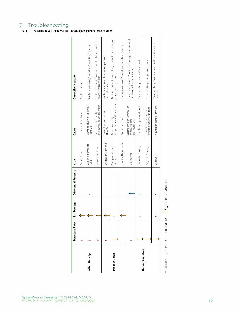
Spiral-Wound Elements | TECHNICAL MANUAL MICRODYN-NADIR | REVISION DATE: 11/12/2020 69
7 Troubleshooting 7.1 GENERAL TROUBLESHOOTING MATRIX

Spiral-Wound Elements | TECHNICAL MANUAL MICRODYN-NADIR | REVISION DATE: 11/12/2020 70
7.2 EVALUATION OF SYSTEM PERFORMANCE
7.2.1 Initial Performance Evaluation
To gain an understanding of a potential change in a system’s performance, it is most useful to evaluate and compare its normalized operating data to the system’s data at start-up. Normalization is a technique that allows the user to compare operation at a specific set of conditions to a reference set of conditions. This allows the user to determine whether changes in flow or rejection are caused by fouling, damage to the membrane or due to different operating conditions. MICRODYN-NADIR offers a Normalization Spreadsheet, which can be downloaded from www.microdyn-nadir.com. If the initial performance at start-up for RO and NF systems has never been satisfactory, a comparison of the actual system performance to the TROI projected system performance under actual conditions may be used to evaluate how a system is operating. Note that TROI’s calculations are estimated to be accurate within ± 10%.
7.2.2 Troubleshooting Checklist
If the normalized performance is unsatisfactory, it is important to check the following:
• Ensure meters, sensors and pressure gauges are calibrated and functioning. Uncalibrated or nonfunctional meters can lead to unintended changes in system performance. Operating at elevated flow rates can result in membrane damage, and operating at flow rates which are too low (or operating above the design recovery rates) can lead to scaling and fouling. Use the general mass balance equations below to confirm the accuracy of flow and conductivity meters. (Note: all equations below should be accurate up to ± 5%). If the accuracy of one of the meters has been compromised, it is recommended to recalibrate or replace it.
For Flow Meters: 𝐹𝐹𝐹𝐹 = 𝑃𝑃𝐹𝐹 + 𝐶𝐶𝐹𝐹 where 𝐹𝐹𝐹𝐹, 𝑃𝑃𝐹𝐹 and 𝐶𝐶𝐹𝐹 are the feed, permeate and concentrate flows.
For Conductivity Meters:
(𝐹𝐹𝐹𝐹)(𝐹𝐹𝐶𝐶) = (𝑃𝑃𝐹𝐹)(𝑃𝑃𝐶𝐶) + (𝐶𝐶𝐹𝐹)(𝐶𝐶𝐶𝐶)
where 𝐹𝐹𝐶𝐶, 𝑃𝑃𝐶𝐶 and 𝐶𝐶𝐶𝐶 are the feed, permeate and concentrate conductivities.
• Determine that the system’s performance has stabilized. Performance typically stabilizes after 24 to 72 hours of continuous operation. Normalized data for systems that have been in operation for an extended time should be investigated for any deviations in performance.
• Consult process and instrumentation diagram (P&ID) and account for system specifics.
Permeate Backpressure Depending on the system design, there may be additional permeate backpressure that has not been
accounted for. This added pressure can cause the feed pressure to be higher than projected. Pressure Losses
Check restrictions in feed or concentrate lines (particularly valves) that may be contributing to higher than expected pressure losses.
Location of the feed and concentrate pressure sensors should be as close to the pressure vessel as possible to gather accurate readings and to avoid close proximity to valves and other places of high turbulence.
• Review chemical compatibility and cleaning regimen.
Cleaning Chemical Compatibility, Effectiveness & Frequency Cleaning chemicals should be approved for membrane compatibility. Consult MICRODYN-NADIR’s Cleaning Guides (found at www.microdyn-nadir.com) to ensure
cleaning effectiveness.

Spiral-Wound Elements | TECHNICAL MANUAL MICRODYN-NADIR | REVISION DATE: 11/12/2020 71
Cleaning frequency will vary by application. For water applications, two to six chemical cleanings per year is generally considered acceptable. A high cleaning frequency may indicate inefficient pretreatment or less than optimal system design and operation.
Higher cleaning frequency may result in higher chemical consumption and lower membrane life. To lower cleaning frequency, it may be economical to invest in pretreatment.
• Check upstream processes / equipment. Prefilters: Prefilters should be regularly monitored and routinely replaced. A high replacement rate may indicate an issue with fouling. Chlorine & other Oxidizing Chemicals: If chlorination or dechlorination is involved upstream of the system, oxidation reduction potential (ORP) should be monitored. Temperature, pH and the presence of transition metals should be scrutinized as they can promote membrane oxidation with the presence of an oxidant. Antiscalants: Antiscalant dosages should be between 2 – 5 ppm. Exceedingly high dosages may result in membrane fouling.
• Perform a water analysis. Transition Metals: Transition metals can catalyze membrane degradation in the presence of an oxidant. Carbon Dioxide (CO2): CO2 passes freely through the membrane. However, in a lower pH environment of the permeate, CO2 can convert into carbonic acid and increase the permeate conductivity. Silt Density Index (SDI): SDI in the feed should consistently be <5 (maximum, depending on the system design). Exceeding this value may cause fouling.
If all the above topics have been considered and the system performance is still unsatisfactory, on-site diagnosis tests should be performed. Please see MICRODYN-NADIR’s guide on Troubleshooting – On-Site Diagnostic Testing (TSG-T-003) for more information. 7.3 ON-SITE DIAGNOSTIC TESTING Underperforming membrane elements are often a symptom of a more serious issue, such as insufficient pretreatment, process upsets or improper system operation. It is recommended to perform the following diagnostic tests before contacting your membrane element supplier regarding a potential warranty claim.
7.3.1 System Troubleshooting Tests
Visual Inspection of Plant Upstream tanks and pipes should be inspected for mold or biogrowth that can infect the membrane system. Membrane systems are particularly susceptible to biofouling when the system is not operating, giving biological contaminants the opportunity to grow and spread. Leaking vessels and pipes should be repaired or replaced. In addition to being a potential entry point for mold or biogrowth, these leaks can also allow air into the system when the system shuts down and lead to hydraulic shock or water hammer at start-up.
Opening the Pressure Vessel Feed Side: The face of the lead element can indicate the presence of colloidal or biological fouling. Colloidal fouling is typically characterized by the presence of particulates or discoloration. Biofouling is typically characterized by its slippery texture and foul odor. Debris on the face of the lead element can indicate a greater system issue and result in higher pressure drop. Concentrate Side: The tail element can indicate the presence of scale or mechanical damage. Scale is typically characterized by the presence of salt crystals and its rough, sandpapery texture. General: Elements should be properly shimmed to avoid element movement within the pressure vessel during start-up and shutdown. Refer to Element Loading Guide – Shimming Elements (TSG-O-008). Additionally, couplers should be inspected for damaged, deformed or misplaced o-rings.

Spiral-Wound Elements | TECHNICAL MANUAL MICRODYN-NADIR | REVISION DATE: 11/12/2020 72
System Cleaning Evaluation How a system responds to cleanings can also be an indication of specific fouling issues. High pH cleanings are often more effective on colloidal, biological and organic fouling. Whereas, low pH cleanings are often more effective on mineral scale. The cleaning solution coming out of the system may also hold valuable information because it may contain high amounts of removed foulants. Analyzing the spent cleaning solution for metals and TOC – and comparing it to an analysis of fresh cleaning solution – can indicate the type of fouling present within the membrane system.
System Profiling Accurately profiling a system, or localizing the source of an issue, requires proper equipment to monitor the performance of each pressure vessel individually. To monitor solute passage, sample ports are commonly placed on the feed line entering each stage and the permeate line exiting each pressure vessel individually (having sample ports on the concentrate lines are also recommended). The solute passage of each pressure vessel may be calculated by measuring the water quality of the samples taken from the feed and permeate ports. Depending on the application and membrane type, various measurements may be used to determine water quality. However, the most common measurement for reverse osmosis and nanofiltration is TDS or conductivity. The permeate water quality may also be tested for specific components using analytical methods. Similar to monitoring solute passage, monitoring permeate flow rate and pressure differential will require the appropriate equipment. Having meters on the feed, concentrate and permeate lines can help locate the origin of a system failure to an individual pressure vessel.
Individual Pressure Vessel Probing If a pressure vessel shows a significantly higher permeate concentration than the other vessels of the same stage, probing allows you to determine and locate the problem within the pressure vessel while remaining online and without unloading the elements. To probe a pressure vessel, please refer to Troubleshooting – Pressure Vessel Probing Procedure (TSG-T-007). 7.4 LOW PERMEABILITY Low permeability, or low flow, is usually the result of an increased resistance to water flow through the membrane. This symptom is most often the result of the accumulated build-up of material from fouling and scaling on the membrane surface. Other less common causes could include pretreatment issues or operational issues. Depending on the system design, this issue may manifest as either a loss of normalized permeate flow or an increase in required feed pressure.
7.4.1 Biofouling
Explanation & Root Cause Biofouling is primarily caused by the combination of a biologically active feed water and improper pretreatment. Biofouling of the membranes is indicated by the following changes in the operating parameters:
• Permeate flow decreases when operated at constant feed pressure and recovery. • Recovery decreases when operated at a constant feed pressure. • Feed pressure has to be increased if the permeate flow is to be maintained at a target permeate flow rate and constant
recovery. This typically increases fouling potential and makes it more difficult to clean later. • Differential pressure increases. Since pressure drop across the pressure vessels can be such a sensitive indicator of
fouling, it is strongly recommended to install pressure gauges to allow monitoring differential pressure within each stage in a system.
• Solute passage increases when fouling occurs. • High counts of microorganisms in water samples taken from the feed, concentrate or permeate streams indicates the
presence of biofouling. • Biofilms typically feel slippery to the touch and often have a bad smell. If burned over a small flame, burnt biofilm smells
similar to that of burnt hair.
Preventative / Corrective Measure If biofouling is present, the following corrective measures are suggested:
• Clean and sanitize the entire system, including pretreatment and elements. Please see MICRODYN-NADIR’s Membrane Cleaning Guides for Water Application Elements (TSG-C-001), Food & Dairy: RO & NF Elements (TSG-C-003), Food & Dairy: UF & MF Elements (TSG-C-004), Cellulose Acetate Elements (TSG-C-005), and/or Food

Spiral-Wound Elements | TECHNICAL MANUAL MICRODYN-NADIR | REVISION DATE: 11/12/2020 73
& Dairy: pHT Elements (TSG-C-007) for cleaning procedures. An incomplete cleaning and disinfection of the system can result in rapid re-contamination.
• Biofouling is often combatted with a high pH soak and rinse. Please see the above cleaning procedures or contact MICRODYN-NADIR Technical Service for details.
• Optimize the pretreatment system to cope with the fouling potential of the raw feed water. • Install fouling-resistant membrane elements. Please contact MICRODYN-NADIR Technical Service for more information.
7.4.2 Colloidal Fouling
Explanation & Root Cause To identify colloidal fouling:
• Review recorded feed water SDI’s and analyze residue from SDI filter pads. • Analyze accumulations on prefilter cartridges. • Analyze deposits on feed scroll end of first stage lead elements.
Preventative / Corrective Measure The corrective measures for colloidal fouling are:
• Clean the elements depending on the foulant type. • Adjust, correct and/or modify the pretreatment.
7.4.3 Compaction / Intrusion
Explanation & Root Cause Low permeate flow and improved salt rejection may be due to membrane compaction or intrusion. Compaction refers to the physical compression of the membrane itself due to very high applied pressures. Compaction causes the membrane itself to lose efficiency and results in a decrease in flux and salt passage. Intrusion, on the other hand, is the when the membrane gets firmly pushed into the channels of the permeate carrier under excessive pressures and temperatures, essentially blocking flow. Intrusion causes high pressure drop on the permeate side of the membrane, causing the element as a whole to lose efficiency. This will result in low permeate flow. For more information on intrusion, please refer to Troubleshooting – Intrusion (TSG-T-009). Preventative / Corrective Measure To correct for compaction and/or intrusion, it is recommended to replace all damaged elements with new ones, preferably elements capable of handling high temperatures and pressures, or add new elements to the system to compensate for the flux decline. If new elements are installed together with used elements, the new elements should be distributed evenly into parallel positions and loaded into the tail positions of a system to prevent them from operating at too high of a flux. Loading vessels exclusively with new elements in parallel with other vessels containing exclusively used elements causes an uneven flow distribution and recovery of the individual vessels. Another way to correct for compaction and/or intrusion is to change the operating parameters. If possible, adjust the operating temperatures and pressures to prevent compaction and/or intrusion.
7.4.4 Incomplete Wetting / Drying Out
Explanation & Root Cause After membrane elements are tested, they are flushed with a preservative solution and then packaged. This preservative solution protects the element’s performance by keeping the pores of the polysulfone layer wet. The polysulfone layer is inherently hydrophobic, so when this is allowed to dry out, the membrane tends to lose flow. When this occurs, the membrane can be re-wetted as described below. Preventative / Corrective Measure When receiving membrane elements, the packaging should be inspected to ensure that no leaking has occurred as a result of mishandling during shipping. After new elements have been removed from their packaging, the amount of time the elements are exposed to open air should be minimized (a few hours maximum). Similarly, special care should be taken for elements that are removed from a system for warranty purposes to ensure the elements do no dry out.

Spiral-Wound Elements | TECHNICAL MANUAL MICRODYN-NADIR | REVISION DATE: 11/12/2020 74
If an element has dried out, the loss in water permeability may be irreversible. However, the elements may be able to be re-wetted as described in Element Storage Guide – Storage & Re-wetting (TSG-O-010).
7.4.5 Metal Oxide Fouling
Explanation & Root Cause Metal oxide fouling occurs predominantly in the first stage and can easily be localized when permeate flow meters have been installed in each array separately. Common sources of metal oxide fouling are:
• Iron or aluminum in feed water. • Hydrogen sulfide with air in feed water results in metal sulfides and/or elemental sulfur. • Corrosion of piping, vessels or components upstream of membrane elements.
To identify metal oxide fouling:
• Analyze the feed water for iron and aluminum. • Check system components for evidence of corrosion. Iron fouling can easily be identified from the element’s appearance
(usually the element is covered in red particles).
Preventative / Corrective Measure The corrective measures for metal oxide fouling are:
• Clean the membrane elements. • Adjust, correct and/or modify the pretreatment. • Retrofit piping or system components with appropriate materials.
7.4.6 Organic Fouling
Explanation & Root Cause The adsorption of organic matter in the feed water on the membrane surface can result in flux loss, especially in the first stage. This adsorption layer can act as an additional barrier for dissolved salts, resulting in a lower salt passage. Organics with a high molecular mass and with hydrophobic or cationic groups such as oil traces or cationic polyelectrolytes (which are sometimes used in pretreatment) can produce such an effect and are very difficult to remove from the membrane surface. To identify organic fouling, check or analyze:
• Deposits from filter cartridges and SDI filter pads. • The incoming water for oil, grease and other organic contaminants. • Pretreatment coagulants and filter aids, especially cationic polyelectrolytes. • Cleaning detergents and surfactants.
Preventative / Corrective Measure If organic fouling is occurring, the following corrective measures are suggested:
• Clean for organics. • Use correct pretreatment. Use minimal coagulant dosages and monitor feed water changes to avoid overdosing. • Modify pretreatment (i.e. oil/water separators).
7.4.7 Scaling
Explanation & Root Cause Scaling originates from the precipitation and deposition of sparingly soluble salts onto the membrane. It typically occurs when a brackish water system is operated at high recovery without the proper pretreatment and usually starts in the last stage and then gradually moves to the upstream stages. Feed waters containing high concentrations of calcium, bicarbonate and/or sulfate can scale a membrane system within hours whereas scaling with barium or fluoride occurs slowly because of the low concentrations involved.

Spiral-Wound Elements | TECHNICAL MANUAL MICRODYN-NADIR | REVISION DATE: 11/12/2020 75
To identify scaling:
• Check the feed water analysis for the scaling potential at the specified system recovery. • Analyze the concentrate for levels of calcium, barium, strontium, sulfate, fluoride, silicate, pH and Langelier Saturation
Index. Try to calculate the mass balance for those salts (analyzing feed water and permeate). • Inspect the concentrate side of the system for scaling. Scaling is hard and rough to the touch – like sand paper and is
difficult to wipe off. • Weigh a tail element as scaled elements are typically heavier. • Autopsy a tail element and analyze the membrane for scaling. The crystalline structure of the deposits can be observed
under a microscope. A foaming reaction with acid indicates carbonate scaling. The type of scaling can be identified by a chemical analysis.
Preventative / Corrective Measure The corrective measures for scaling include:
• Cleaning the membranes with acid and/or an alkaline solution. An analysis of the spent solution may help to verify the cleaning effectiveness.
• Optimize cleaning depending on scaling salts present. • Carbonate scaling: lower pH, adjust antiscalant dosage. • Sulfate scaling: lower recovery, adjust type of antiscalant and dosage. • Fluoride scaling: lower recovery, adjust type of antiscalant or dosage.
7.5 HIGH SOLUTE PASSAGE High solute passage at normal permeate flow may be due to different causes including a membrane or element defect, leaking o-rings, membrane oxidation, membrane surface abrasions, permeate backpressure damage or element telescoping.
7.5.1 Membrane or Element Defect
Explanation & Root Cause A membrane or element defect is typically noticed at or shortly after start-up. Membrane or element defects can be caused by a variety of things: a weak spot in the membrane itself, a manufacturing or workmanship error or mechanical damage to the element during shipping or loading. When a membrane or element defect is present, often times, both salt passage and permeate flow increases. Preventative / Corrective Measure A membrane or element defect may be detected by the probing technique described in Troubleshooting – Pressure Vessel Probing Procedure (TSG-T-007). Replace leaking elements and correct the cause for the leakage.
7.5.2 Leaking O-Ring
Explanation & Root Cause A leaking o-ring is typically noticed at or shortly after start-up. O-rings may leak if rolled or damaged during element loading, exposed to certain chemicals causing them to degrade or if the wrong size o-ring is used. Preventative / Corrective Measure Leaking o-rings can be detected by the probing technique. To prevent leaking o-rings, be sure to inspect o-rings of couplers, adapters and end plugs for correct installation and condition. Replace any old and/or damaged o-rings. For replacement o-rings, please contact MICRODYN-NADIR Technical Service. Additionally, proper shimming of the elements in a pressure vessel is essential to minimize the wear to the seats, especially during events of water hammer. Refer to Element Loading Guide – Shimming Elements (TSG-O-008).
7.5.3 Membrane Oxidation
Explanation & Root Cause Membrane oxidation damage usually results in high salt passage in combination with a higher than normal permeate flow. When free chlorine, bromine, ozone or other oxidizing chemicals are present in the feed water, the front end elements are typically more at risk than the others.

Spiral-Wound Elements | TECHNICAL MANUAL MICRODYN-NADIR | REVISION DATE: 11/12/2020 76
Disinfecting when pH and temperature limits are not maintained or when in presence of iron or other transition metals may catalyze the reaction between the disinfectant and membrane surface. Continuous exposure to the combination of iron (or other transition metals) and hydrogen peroxide solutions may eventually damage the membrane. Preventative / Corrective Measure An autopsy of the element and an analysis of the membrane can be used to confirm the damage. This is most frequently done using a Fujiwara (to detect the presence of halogens) or dye test. Unfortunately, no corrective action is possible to restore the membrane. Identify the oxidizing agent and remove it, or utilize pretreatment methods to remove the oxidizing agent before it comes into contact with the membrane. All damaged elements should be replaced.
7.5.4 Membrane Surface Abrasion
Explanation & Root Cause Sharp particles in the feed water may enter the feed channels and scratch the membrane surface. This can lead to an increase in salt passage, primarily in the lead elements. Preventative / Corrective Measure Check the incoming water for such particles and inspect the membrane surface with a microscope to detect damage. To ensure that no particles are released from the pump and the high pressure piping, check the system’s prefiltration and be sure that the piping has been rinsed out before the start-up. It is also highly recommended to replace damaged membranes.
7.5.5 Permeate Backpressure
Explanation & Root Cause Permeate backpressure is when the permeate pressure exceeds the feed/concentrate pressure. Such a situation typically causes reverse flow and damages the membrane. As a rule of thumb, when the permeate pressure exceeds the concentrate pressure by more than 0.35 bar (5 psi) at any time, the membrane is subject to the possibility of damage. When a leaf of an element subjected to permeate backpressure is unrolled, the outer membrane typically exhibits creases parallel to the permeate tube, close to the outer glue line. The membrane may delaminate from the support layer and even form blisters against the feed spacer. Preventative / Corrective Measure The damage caused by excessive backpressure can be identified by probing and a leak test and confirmed by a visual inspection during autopsy. Replace damaged elements and correct the cause. Check piping and/or the possibility of including check or atmospheric drain valves to help prevent reverse permeate flow.
7.5.6 Telescoping
Explanation & Root Cause Telescoping is a mechanically damaging effect to the element where the outer diameter of the element protrudes downstream past the permeate tube. Because of the anti-telescoping devices (ATDs), which are part of a standard water purification element, the primary cause of telescoping is the lack of a thrust ring in the pressure vessel. During telescoping, the ATD will be damaged and in severe cases, the glue line and/or the membrane be damaged. Preventative / Corrective Measure Although this may be due to excessive pressure drop, telescoping is almost always due to the lack of having a thrust ring installed. Additionally, telescoping almost exclusively affects only the last element in the pressure vessel. If telescoping is evident, replace the damaged element(s), correct the causes and ensure thrust rings are installed. 7.6 HIGH DIFFERENTIAL PRESSURE Pressure drop is the loss of pressure from the feed end to the concentrate end of an element or pressure vessel and occurs due to the resistance of flow. For example, if water is flowing through a pipe of 1” in diameter and then flows through another pipe of ½” in diameter, the water experiences a greater resistance to flow in the smaller pipe creating a pressure drop within the pipe. Because pressure drop occurs due to the resistance of flow, it is a function of feed flow rate, feed spacer thickness and feed spacer geometry. Under normal operating conditions, the pressure drop of a reverse osmosis (RO) element is about 0.3 bar (4 to 5 psi).

Spiral-Wound Elements | TECHNICAL MANUAL MICRODYN-NADIR | REVISION DATE: 11/12/2020 77
Pressure drop may increase due to debris blocking the feed channels, fouling or scaling within a system, water hammer, or excessive feed flow. A high pressure drop may be problematic because it may lead to telescoping of the membrane, inefficient operation and an overall decline in system performance. The maximum recommended pressure drop across a single fiberglass element is 1.0 bar (15 psi) or 4.0 bar (60 psi) across multiple elements in a pressure vessel, whichever value is more limiting. Interstage pressure indicators are recommended to assess RO plant performance, especially in the case of surface and city waters since these water sources tend to contribute to high rates of fouling. Interstage pressure indicators enable the pressure drop of each stage to be calculated (feed pressure minus concentrate pressure) so the location (i.e. stage) of the potential performance problem can be more accurately identified. Measuring only the total pressure drop of a system may potentially conceal a problem within the system. While the total pressure drop value may be acceptable to determine if there is a system upset, it is possible that the pressure drop mainly occurs in one stage. In that case, the membrane elements in that particular stage may already be damaged.
7.6.1 Causes & Preventative Measures for High Differential Pressure
The effects of high pressure drop on elements may include:
• Fiberglass elements may crack or break circumferentially near the ATD. • The spokes of the endcap or ATD may break. • The feed spacer may extrude past the scroll end.
Although the damage described above is easily visible, it does not normally affect the membrane performance directly. However, such damage may indicate that the differential pressure is too high. Cracks around the endcap or ATD may cause bypass of feed water and may lead to fouling and scaling. There are a few root causes that may lead to differential pressure in a membrane system including debris, fouling and scaling, water hammer and excessive feed flow. Debris To prevent large debris from entering and blocking the flow channels in lead-end elements, cartridge filters are often placed before membrane systems to filter out such debris. However, when cartridge filters are loosely installed in their housing, connected without interconnectors or haven’t been installed at all, debris bypass the filter and block the feed spacers. Sometimes cartridge filters will deteriorate while in operation due to water hammer or hydraulic shock, or in the presence of incompatible materials. Occasionally, some of the finer media from sand, multimedia, carbon, weak acid cation exchange resin or diatomaceous earth pretreatment filters may break free into the system feed water. It is recommended to check cartridge and pretreatment media filters regularly to ensure they have not deteriorated and to prevent membrane fouling downstream. Fouling & Scaling An increase in differential pressure at constant flow rates is usually due to the presence of debris, foulants or scale within the element flow channels (feed spacer). As foulants and scale tends to build up in the feed channels, the feed water experiences a greater resistance to flow and may lead to high pressure drop as well as a decline in system performance. Because foulants or scale may cause high pressure drop, it is important to clean the system regularly using a proper cleaning regime. To determine which cleaning method to use, please refer to MICRODYN-NADIR’s various Cleaning Guides. Additionally, ensure that the designed system recovery is not exceeded. Water Hammer High pressure drop may also occur when the feed pressure builds up too fast during start-up, known as water hammer. Water hammer, a hydraulic shock to the membrane element, can also occur when the system is started up before all the air has been flushed out. This can happen when the system has been allowed to drain prior to start-up. To prevent air from entering into the system, install vacuum breakers to ensure that the pressure vessels are not under vacuum when shut down. Starting up a partially drained system causes the pump to suck water at great velocities and hammering the elements. Additionally, the high pressure pump may be subject to cavitation if air bubbles are present in the partially drained system.

Spiral-Wound Elements | TECHNICAL MANUAL MICRODYN-NADIR | REVISION DATE: 11/12/2020 78
Excessive Feed Flow An excessive pressure drop may also occur when the recommended maximum feed flow rates are surpassed. When systems are fed an excessive amount, pressure builds up within the elements and pressure vessel. It is important to follow the guidelines and recommendations given by the membrane supplier to determine what the maximum feed flow rates are for particular membranes. 7.7 COMPACTION & INTRUSION As referenced in Troubleshooting – Low Permeability (TSG-T-004), low permeate may be due to membrane compaction or intrusion. When exposed to high pressures and temperatures, the phenomena of compaction and intrusion are often times confused even though one involves the membrane itself while the other involves the element as a whole. The following guide is intended to clarify and distinguish the two. For additional information or questions, please contact MICRODYN-NADIR Technical Service.
7.7.1 Compaction
Membrane compaction refers to the physical compression of the membrane itself. The effect of compaction is more significant in asymmetric cellulose acetate (CA) membranes than in thin-film composite membranes. When a CA membrane undergoes compaction, the asymmetric membrane itself becomes compressed. Thin-film membranes, on the other hand, have greater structural strength than CA membranes due to their microporous polysulfone substrate interlayer (explained in further detail in Membrane Chemistry – Cellulose Acetate vs. Thin-Film Composite (TB-017)). This interlayer lies between the dense polyamide or piperazine barrier layer and the non-woven polyester support layer. This combination of the microporous polysulfone substrate and non-woven polyester support layer allows the barrier layer to withstand high operating pressures. So when a thin-film membrane undergoes compaction, the polysulfone substrate collapses rather than the membrane compressing as found with CA membranes. Compaction typically occurs when the element is subjected to very high applied pressures. This compression results in a decrease in flux (and salt passage) and causes the membrane itself to lose efficiency. A compacted membrane will perform similarly to the element itself.
7.7.2 Intrusion
Intrusion generally occurs when the element is subjected to a combination of very high pressure and temperature. The term “intrusion” is based on the membrane being pushed (or intruded) into the channels of the permeate carrier. When this happens, the channels of the permeate carrier where the permeate flows to the permeate tube are partially blocked, hindering flow and creating a permeate-side pressure drop. This results in lower permeate flow, which is irreversible. Unlike compaction, intrusion causes the element as a whole to lose efficiency. Because the polymeric components of a spiral-wound element tend to soften at elevated temperature, intrusion is far more common in applications where the feed temperature is above 35°C (95°F). While compaction cannot be seen by the naked eye, one can clearly see concave scroll ends of elements that have experienced intrusion. When the membrane leaf gets pushed into the channels of the permeate carrier, the result is an element with concave scroll ends at both the lead and tail ends of the element (Figure 19A and 19C). This is not to be confused with an element that has experienced membrane telescoping, where the affected element’s lead end is concave and tail end is convex (Figure 19B). Membrane telescoping is usually the result of operation without a pressure vessel thrust ring. Additionally, with intrusion, there may be some membrane damage from deformation of the membrane over the weaves of the permeate carrier. When membrane from an element affected by intrusion is removed and cell tested, it will typically have higher flux (and often higher salt passage) than the element.

Spiral-Wound Elements | TECHNICAL MANUAL MICRODYN-NADIR | REVISION DATE: 11/12/2020 79
7.7.3 Special Construction
Because compaction and/or intrusion occur(s) at higher pressures and/or temperatures than the element was originally designed for, it is recommended to use elements that are capable of handling such harsh conditions. Typically, such processes call for customized (high pressure/high temperature construction) elements. In order to select the proper element construction for these particular applications, it is important to understand the Wagner Unit. Coined by Jorgen Wagner, an engineer involved with membranes since the 1970’s, Wagner Units help to consider the limits of different element construction. Figure 20 demonstrates what kind of construction is necessary at particular operating conditions. The Wagner Units are calculated by multiplying the operating temperature (in °C) and operating pressure (in bar). For Wagner Units below 1200, a standard element will generally meet the requirements. Seawater RO and most process elements are capable of up to 2,000 Wagner Units. When the Wagner Units for an application are above 2,000, special element construction is often required. MICRODYN-NADIR offers high temperature elements capable of continuous operation at up to 80°C (176°F) and ultra-high pressure elements capable of operating at pressure up to 100 bar (1,500 psi) to meet the demands of challenging applications.
Figure 19. A) Elements that experience intrusion have concave scroll ends at both ends of the element. B) Elements that experience telescoping are usually concave at the lead end of the element and convex at the tail end of the element. C) An example of an element that has experienced intrusion. As depicted by the curved arrow, the scroll end towards the outer (near outerwrap) and inner (near permeate tube) perimeters of the element are level. The scroll end between the permeate tube and outerwrap, however, appear sunken. This can also be seen by the indentations on the scroll end by the ATD spokes. The indentations are more pronounced near the outerwrap as well as near the permeate tube, whereas the indentions are less pronounced otherwise.
Indentations from
ATD Spokes
Concave Scroll End
INTRUSION
TELESCOPING
Concave Scroll End
Convex Scroll End
Concave Scroll End
Concave Scroll End
A)
B)
C)
Figure 20. Wagner Units are determined by multiplying the operating temperature (in °C) and operating pressure (in bar). The following guidelines are helpful in determining when a custom element is necessary for a particular application: < 1,200: Standard element applicable 1,200 – 2,000: Seawater RO or process elements > 2,000: Custom solution
10
20
30
40
50
60
70
80
90
10 20 30 40 50 60 70 80 90 100
Tem
pera
ture
(°C
)
Pressure (bar)
High Temp. Construction
Contact Element Supplier
Standard Elements
Standard Seawater RO
or Process Ultra-High Pressure

Spiral-Wound Elements | TECHNICAL MANUAL MICRODYN-NADIR | REVISION DATE: 11/12/2020 80
7.8 JAR TESTING PROCEDURE The following jar test procedure is intended to simulate the coagulation/flocculation process and determine appropriate dosages. The lab-scale results are used to optimize the performance of systems such as water treatment plants by determining the concentration of coagulant to be added to the source water. For further instruction, please contact MCIRODYN-NADIR Technical Service.
7.8.1 Equipment
For the jar testing procedure, you will need the equipment listed in Table 17. TABLE 17. NECESSARY EQUIPMENT FOR JAR TEST PROCEDURE.
Required Optional
1,000 mL Graduated Cylinder 6 Magnetic Stirrers
(6) 1,000 mL Beakers * Magnetic Stirring Device
Aluminum Sulfate (Alum) Stock Solution (1.0% by weight) ** Turbidimeter
(5) 10 mL Pipettes Sample Tubes
Stopwatch or Clock
* Alternative beaker sizes may be used; alum dosages should be adjusted accordingly. ** See Alum Solution Preparation for Dry Products and Liquid Products below.
7.8.2 Alum Solution Preparation
If an alum stock solution of 1.0% by weight is not on hand, please follow the guidelines below to prepare a solution. Dry Products: Weigh 10 grams of chemical and dissolve in DI water to make a 1,000 mL solution. This is a 10 g/L solution or 1.0% by weight. 1 mL of this solution in a 1 L test beaker = 1 mL/L = 10 ppm. Liquid Products: Liquid aluminum sulfate (alum) is typically sold and accounted for on a dry basis which is 48.5% Al2(SO4)3 • 14 H2O. Specific gravity is 1.335 ± 0.005. For example: 10.0 grams / (1.335 x 0.485) = 15.4 mL liquid alum for a 10 g/L (1.0% by weight) dry basis solution. 1 mL of this solution in a 1 L jar test beaker = 10 ppm dry alum.

Spiral-Wound Elements | TECHNICAL MANUAL MICRODYN-NADIR | REVISION DATE: 11/12/2020 81
7.8.3 Procedure
The procedure for a jar test is as follows:
1. Using a 1,000 mL graduated cylinder, add 1,000 mL of raw feed water to be coagulated to each of the jar test beakers. 2. Using a prepared alum stock solution (1.0% by weight), dose each beaker with increasing amounts of solution shown in
Table 18.
TABLE 18. INCREASING DOSAGES OF ALUM.
Jar # Alum Added (mL) Alum Dosage (mg/L)
Control 0.0 0.0
1 0.5 5.0
2 1.0 10.0
3 1.5 15.0
4 2.0 20.0
5 2.5 25.0
3. After dosing each beaker, turn on the stirrers (if these aren’t available, swirl beaker by hand to mix the alum and feed water
solution) to a setting that best mimics the plant’s operation as shown in Table 19.
TABLE 19. PLANT OPERATION VS. JAR TEST PROCEDURE OPERATING PARAMETERS.
Current Plant Operation Jar Test Procedure
1. Alum addition followed by static mixing
2. Flocculation for 35 minutes
3. Settling for 90 minutes
1. Alum addition followed by mixing at a high RPM
2. Reduce mixing speed to match conditions in the flocculator for 35 minutes
3. Turn off mixer to match conditions in the settler for 90 minutes
4. Examine the beakers and determine which dosage produced the best results (i.e. Figure 21). Under-dosing coagulant will
cause the sample to look cloudy with little or no floc and almost no settling. Over-dosing coagulant will cause a dense fluffy floc to occur and will not settle well. The beaker with an appropriate dosage of coagulant will have floc that has settled to the bottom and the water above it will be clear. If none of the beakers appear to have good results then the procedure should be run again using different dosages until the correct dosage is determined.
Figure 18. The beakers on the left are under-dosed with coagulant and appears cloudy with little or no floc and almost no settling. The beakers on the far right, however, appear to have floc that has settled to the bottom and the water above looks clear. In this figure, the beaker on the far right exemplifies the correct coagulant dosage.

Spiral-Wound Elements | TECHNICAL MANUAL MICRODYN-NADIR | REVISION DATE: 11/12/2020 82
7.9 PRESSURE VESSEL PROBING PROCEDURE The following are general recommendations for probing a pressure vessel. Probing a pressure vessel allows you to determine and pinpoint where a specific problem lies within a particular vessel. For questions or additional information on pressure vessel probing, please contact MICRODYN-NADIR Technical Service.
7.9.1 Procedure
If one pressure vessel shows a significantly higher permeate concentration than the other vessels of the same stage, probing allows you to determine and locate the problem within the pressure vessel while remaining online and without unloading the elements. To probe a pressure vessel:
1. Obtain a plastic tube (approximately 6 mm (¼ inch) in diameter and a length longer than the pressure vessel to be probed). To easily access desired sampling locations, mark the tube every 20 cm (8 inches) so that every fifth sample should mark the coupling connection between two 40” long elements. Sampling every 20 cm allows for multiple measurements per element plus the checking of all coupler/adapter o-rings for leaks.
2. Disconnect the housing from the permeate manifold and isolate the pressure vessel to be probed. Open the permeate port.
3. Insert a plastic tube into the permeate tube (using the open permeate port) in order to measure the permeate conductivity at different locations inside the pressure vessel. Push the tube all the way into the pressure vessel.
4. Allow a few minutes for the system to operate at normal operating conditions so that the system reaches steady-state. 5. For an RO system, the TDS or conductivity of the permeate sample (from the tubing) can be measured with a hand-held
meter. This measurement should reflect the TDS of the permeate being produced by the element at that particular position. For a NF system, a conductivity meter might not be sensitive enough to localize a leakage. In this case, permeate samples should be measured and recorded for analysis for appropriate solutes, such as sulfates. The same is true for UF and MF systems where TSS may be used as a measurement.
6. Pull out the tubing 15 cm (6 inches) from the end and measure a new sample at the adaptor/element interface. 7. Pull the tubing out another 20 cm (8 inches) and take another sample. 8. Continue step 6 to obtain a conductivity profile. A normal conductivity profile should show a steady increase in permeate
concentration produced at the feed end towards the concentrate end of the pressure vessel. Any deviation from this normal profile demonstrates where a high salt passage problem may be located within the pressure vessel. O-ring problems are usually indicated by a step change in the conductivity profile at coupler/adapter locations. Element leakages are indicated by an increase in the conductivity profile outside of the coupler/adapter locations.
Note: The normal (reference) conductivity profile depends on the location of the probing tube entry and on the flow direction of the permeate out of the probed vessel. The first sample from the feed end of the vessel is the permeate produced at exactly that location. As the tube is pulled out of the vessel, the sample consists of the combined permeate which is produced upstream of the sample location and the permeate produced at that location. The very last sample is the permeate of the entire vessel. If the pressure vessel is connected to the permeate manifolds and/or the probing tube is inserted from the feed side of the vessel, the reference conductivity profile changes accordingly.

Spiral-Wound Elements | TECHNICAL MANUAL MICRODYN-NADIR | REVISION DATE: 11/12/2020 83
7.10 MEASURING SILT DENSITY INDEX (SDI) The potential for particulate and colloidal fouling in water purification systems can be estimated by the Silt Density Index (SDI). This is done by measuring the time for 500 mL of the feed water to filter through a 0.45 μm membrane at 2.0 bar (30 psi). TRISEP® RO & NF membranes require a feed SDI of <5 at all times. SDI measurements should be scheduled on a regular basis for RO and NF membrane systems. While there is no direct correlation between SDI and turbidity, generally feed waters with a turbidity <1 NTU have an SDI <5 and have very low fouling potential. ASTM Standard D 4189 defines the procedures for this test.
7.10.1 Equipment
The following equipment is needed to perform an SDI measurement. Figure 22 illustrates the test set-up. Numbers in the diagram reference the following numbered list:
1. Needle valve or other pressure regulating valve 2. ¼” ball valve 3. 0 – 5.0 bar (0 – 70 psi) pressure gauge 4. 47 mm (1.85 inches) diameter filter holder 5. 0.45 μm membrane filter (47 mm diameter) 6. 500 mL graduated cylinder 7. Thermometer 8. Tweezers 9. Stopwatch
1 2
P
3
E-1
4
5
500 ml
6
Figure 19. SDI test set-up.

Spiral-Wound Elements | TECHNICAL MANUAL MICRODYN-NADIR | REVISION DATE: 11/12/2020 84
7.10.2 Test Procedure
1. Measure the feed water temperature, and ensure that the beginning and ending feed temperature does not increase or decrease by more than 1°C (33.8°F).
2. Insert the 0.45 μm membrane filter into the filter holder. Avoid touching the filter with fingers. Use dull tweezers to avoid damaging the filter.
3. Bleed entrained air and tighten the O-ring seal. 4. Adjust the pressure regulator to 2.0 bar (30 psi). 5. Open the ball valve completely and start the timer. Stop the timer once the graduated cylinder has filled to 500 mL.
Record this time as 𝑡𝑡𝑖𝑖 . 6. Allow the feed water to continue filtering for 15 minutes. 7. Repeat the step 5, however this time record the time as 𝑡𝑡𝑓𝑓. 8. Retain the filter sample for future reference.
7.10.3 Calculation
The following calculation can be used to determine the feed water SDI:
𝑆𝑆𝑆𝑆𝑆𝑆 =�1 − 𝑡𝑡𝑖𝑖
𝑡𝑡𝑓𝑓� × 100
15
where 𝑡𝑡𝑖𝑖 is the time measured for 500 ml of feed water to filter initially, and 𝑡𝑡𝑓𝑓 is the time measured for 500 ml of feed water to filter after 15 minutes. The maximum allowable SDI value for TRISEP® membranes is 5.0. If the SDI value is >5.0, additional pretreatment should be considered. In order to reduce the amount of cleaning needed, RO & NF feed water will ideally have an SDI <3.0.


![NADiR METAL RAFINERI]](https://static.fdocuments.net/doc/165x107/628dec053279ea5a0b392aa6/nadir-metal-rafineri.jpg)


