Micro S-1™ User manual - The Originator of the Red Dot Sight · 1 PRESENTATION Aimpoint® red dot...
12
Micro S-1™ User manual
Transcript of Micro S-1™ User manual - The Originator of the Red Dot Sight · 1 PRESENTATION Aimpoint® red dot...
Micro S-1™ User manual

1 PRESENTATION Aimpoint® red dot sights are designed for the ”two eyes open” method which greatly enhances situational awareness and target acquisition. The red dot follows the movement of the user’s eye while remaining fixed on target, eliminating any need for centering.
1.1 Technical specification
Optical systemMagnification 1XEye relief UnlimitedClear aperture 18 mmNVD2 compatible NoOptical coating Anti-reflection (AR) coatingAdjustments 1 click = 13 mm @ 100 m
1/2” @ 100 ydsAdjustment range ±1 m @ 100 m / ±1 yds @ 100 ydsDot size 6 MOA1
Dot intensity settings
12 settings manually adjusted with rotary switch
Dot color Red (655 nm ± 10 nm)Signature No forward optical signature from
the dot beyond 10 meters
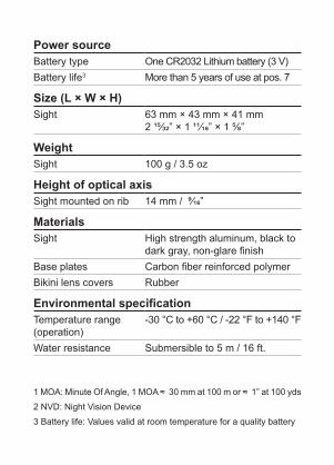
Power sourceBattery type One CR2032 Lithium battery (3 V)Battery life3 More than 5 years of use at pos. 7
Size (L × W × H)Sight 63 mm × 43 mm × 41 mm
2 15/32” × 1 11/16” × 1 5/8”
Weight Sight 100 g / 3.5 oz
Height of optical axisSight mounted on rib 14 mm / 9/16”
MaterialsSight High strength aluminum, black to
dark gray, non-glare finishBase plates Carbon fiber reinforced polymerBikini lens covers Rubber
Environmental specificationTemperature range (operation)
-30 °C to +60 °C / -22 °F to +140 °F
Water resistance Submersible to 5 m / 16 ft.
1 MOA: Minute Of Angle, 1 MOA ≈ 30 mm at 100 m or ≈ 1” at 100 yds2 NVD: Night Vision Device3 Battery life: Values valid at room temperature for a quality battery
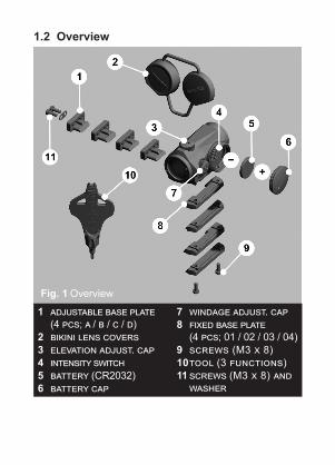
1.2 Overview
1 adjustable base plate (4 pcs; a / b / c / d)
2 bikini lens covers3 elevation adjust. cap4 intensity switch5 battery (CR2032)6 battery cap
7 windage adjust. cap8 fixed base plate
(4 pcs; 01 / 02 / 03 / 04)9 screws (M3 x 8)10 tool (3 functions)11 screws (M3 x 8) and
washer
Fig. 1 Overview
2 OPERATIONWARNING: Ensure the weapon is not loaded and the safety selector is in the ”safe” position before attempting to install, remove or perform maintenance.
2.1 Install battery1 Remove the battery cap using the tool. 2 Insert battery (CR2032) with the positive end (+)
toward the battery cap as can be seen in Fig. 1.
CAUTION: Check that the o-ring of the battery cap is in good condition and in position to ensure there is no water leakage into the battery compartment.
3 Turn the intensity switch to intensity setting 12 (max.) and tighten the battery cap with the tool. When resistance is encountered, proceed to tighten until the battery cap comes to a stop.
4 Verify the red dot is visible and there is zero gap between the battery cap and the battery compartment.
NOTE: Remove battery (CR2032) before putting the sight in storage for extended periods.
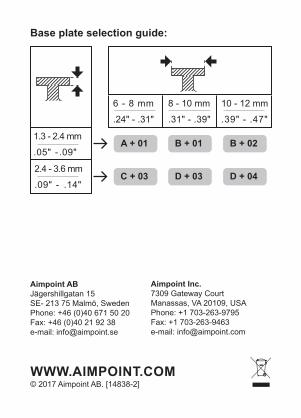
2.2 Preparations for mountingThe sight comes with 8 interchangeable base plates to provide a secure mount for most shotgun rib dimensions. Use a caliper to measure the dimensions of the shotgun rib to determine which combination of base plates to use.
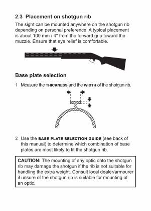
2.3 Placement on shotgun ribThe sight can be mounted anywhere on the shotgun rib depending on personal preference. A typical placement is about 100 mm / 4" from the forward grip toward the muzzle. Ensure that eye relief is comfortable.
Base plate selection 1 Measure the thickness and the width of the shotgun rib.
2 Use the base plate selection guide (see back of this manual) to determine which combination of base plates are most likely to fit the shotgun rib.
CAUTION: The mounting of any optic onto the shotgun rib may damage the shotgun if the rib is not suitable for handling the extra weight. Consult local dealer/armourer if unsure of the shotgun rib is suitable for mounting of an optic.
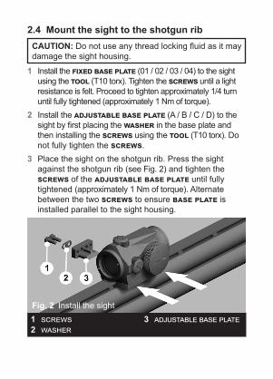
2.4 Mount the sight to the shotgun ribCAUTION: Do not use any thread locking fluid as it may damage the sight housing.
1 Install the fixed base plate (01 / 02 / 03 / 04) to the sight using the tool (T10 torx). Tighten the screws until a light resistance is felt. Proceed to tighten approximately 1/4 turn until fully tightened (approximately 1 Nm of torque).
2 Install the adjustable base plate (A / B / C / D) to the sight by first placing the washer in the base plate and then installing the screws using the tool (T10 torx). Do not fully tighten the screws.
3 Place the sight on the shotgun rib. Press the sight against the shotgun rib (see Fig. 2) and tighten the screws of the adjustable base plate until fully tightened (approximately 1 Nm of torque). Alternate between the two screws to ensure base plate is installed parallel to the sight housing.
1 screws2 washer
3 adjustable base plateFig. 2 Install the sight
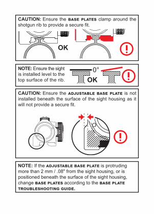
CAUTION: Ensure the base plates clamp around the shotgun rib to provide a secure fit.
OK
NOTE: Ensure the sight is installed level to the top surface of the rib. OK
0°
CAUTION: Ensure the adjustable base plate is not installed beneath the surface of the sight housing as it will not provide a secure fit.
NOTE: If the adjustable base plate is protruding more than 2 mm / .08" from the sight housing, or is positioned beneath the surface of the sight housing, change base plates according to the base plate troubleshooting guide.
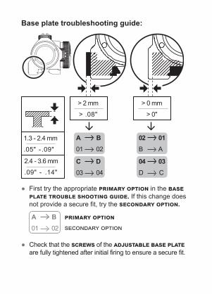
Base plate troubleshooting guide:
1.3 - 2.4 mm
.05" - .09"
2.4 - 3.6 mm
.09" - .14"
> 2 mm
> .08"
> 0 mm
> 0"
02 01 B A
04 03 D C
A B 01 02
C D 03 04
● First try the appropriate primary option in the base plate trouble shooting guide. If this change does not provide a secure fit, try the secondary option.
A B 01 02
primary optionsecondary option
● Check that the screws of the adjustable base plate are fully tightened after initial firing to ensure a secure fit.
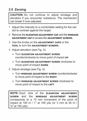
2.5 ZeroingCAUTION: Do not continue to adjust windage and elevation if you encounter resistance. The mechanism can break if over-adjusted.
1 Adjust the intensity to a comfortable setting for the red dot to contrast against the target.
2 Remove the elevation adjustment cap and the windage adjustment cap to access the adjustment screws.
3 Use the knobs on the adjustment caps or the tool to turn the adjustment screws.
4 Adjust elevation (see Fig. 3): ● Turn elevation adjustment screw counterclockwise to move point of impact up.
● Turn elevation adjustment screw clockwise to move point of impact down.
5 Adjust windage (see Fig. 4): ● Turn windage adjustment screw counterclockwise
to move point of impact to the right. ● Turn windage adjustment screw clockwise to move point of impact to the left.
NOTE: Each click of the elevation adjustment screw and the windage adjustment screw corresponds to a 13 mm movement of the point of impact at 100 m / 1” at 100 yds (or 3 mm at 25 m / 1/8" at 100 yds).

Fig. 3 Adjust elevation Fig. 4 Adjust windage
3 EXTREME CONDITIONS ● Extreme heat (moist or dry): no special procedures required. ● Extreme cold: extreme cold might shorten battery life. ● Sea spray, water, mud, snow: ensure the battery cap is
tightened. Keep lens covers on. Clean lenses and wipe the sight dry after exposure.
● Salt air: no special procedures required. ● High altitudes: no special procedures required.
CAUTION: Never clean the lenses with fingers. Use lens paper/cloth. If lens paper/cloth is not available:
● To clear away debris (sand, grass etc.): blow away the dirt or rinse with clear water.
● To clean lenses: fog the lenses or rinse with clear water and clean them with a soft piece of cloth.
© 2017 Aimpoint AB. [14838-2]
Aimpoint ABJägershillgatan 15SE- 213 75 Malmö, SwedenPhone: +46 (0)40 671 50 20Fax: +46 (0)40 21 92 38e-mail: [email protected]
WWW.AIMPOINT.COM
Aimpoint Inc.7309 Gateway CourtManassas, VA 20109, USAPhone: +1 703-263-9795Fax: +1 703-263-9463e-mail: [email protected]
Base plate selection guide:
1.3 - 2.4 mm
.05" - .09"
2.4 - 3.6 mm
.09" - .14"
6 - 8 mm
.24" - .31"
8 - 10 mm
.31" - .39"
10 - 12 mm
.39" - .47"
A + 01
C + 03
B + 01
D + 03
B + 02
D + 04


![MPS3™ with MGMount User manual - Aimpoint · 2016. 6. 28. · [11843-1] 2.2 Zeroing The sight is delivered with the red dot in a centered position. Normally, this means that only](https://static.fdocuments.net/doc/165x107/6018774630e78c1172517396/mps3a-with-mgmount-user-manual-aimpoint-2016-6-28-11843-1-22-zeroing.jpg)


