Micro Programmable Controller CPM2A
26
Micro Programmable Controller CPM2A A--46 Micro Programmable Controller CPM2A The CPM2A brick-style controllers offer one of the most powerful, small-scale control solutions in the industry today. They provide 20, 30, 40 or 60 I/O point CPUs, pulse I/O for position control, multiple communications ports and a powerful instruction set. D Expandable up to 120 I/O points D Peripheral and RS-232C ports standard for direct connection to serial devices and programming tools D Removable terminals D Synchronized pulse control coordinates input devices with control devices D Auxiliary 24 VDC supply (AC type only) D Relay or Transistor outputs D Analog I/O expansion modules available D Temperature sensor input expansion modules available D Real-time clock D 20 kHz high-speed counter input D Two, 10 kHz pulse outputs for position control applications Basic Configuration Up to three Expansion I/O Modules or Special I/O Modules can be connected to any CPM2A CPU. The mounting order does not affect the number of modules that can be mounted. CPU Expansion I/O Module or Special I/O Module Expansion I/O Module or Special I/O Module Expansion I/O Module or Special I/O Module Optional Serial Com- munications Adapters CPM1-CIF01/CIF11 modify the Peripheral Port for use as an additional serial port.
Transcript of Micro Programmable Controller CPM2A

Micro Programmable Controller CPM2AA--46
Micro Programmable Controller
CPM2AThe CPM2A brick-style controllers offer one ofthe most powerful, small-scale control solutionsin the industry today. They provide 20, 30, 40or 60 I/O point CPUs, pulse I/O for positioncontrol, multiple communications ports and apowerful instruction set.
D Expandable up to 120 I/O points
D Peripheral and RS-232C ports standard for directconnection to serial devices and programming tools
D Removable terminals
D Synchronized pulse control coordinates input deviceswith control devices
D Auxiliary 24 VDC supply (AC type only)
D Relay or Transistor outputs
D Analog I/O expansion modules available
D Temperature sensor input expansion modules available
D Real-time clock
D 20 kHz high-speed counter input
D Two, 10 kHz pulse outputs for position controlapplications
Basic ConfigurationUp to three Expansion I/O Modules or Special I/O Modules can be connected to any CPM2A CPU. The mounting order does not affectthe number of modules that can be mounted.
CPU Expansion I/O Moduleor Special I/O Module
Expansion I/O Moduleor Special I/O Module
Expansion I/O Moduleor Special I/O Module
Optional Serial Com-munications AdaptersCPM1-CIF01/CIF11modify the PeripheralPort for use as anadditional serial port.

A--47Micro Programmable Controller CPM2A
Ordering InformationJ CPU
Stock Note: Shaded models are normally stocked.
Description Inputi t
Outputi t
Powerl
Part numberp ppoints
ppoints supply Relay outputs Transistor outputsy p
NPN (Sinking) PNP (Sourcing)
CPUs with 20 I/O points 12 8 AC CPM2A-20CDR-A — —
AC model DC models
DC CPM2A-20CDR-D CPM2A-20CDT-D CPM2A-20CDT1-D
CPUs with 30 I/O points 18 12 AC CPM2A-30CDR-A — —
AC model DC models
DC CPM2A-30CDR-D CPM2A-30CDT-D CPM2A-30CDT1-D
CPUs with 40 I/O points 24 16 AC CPM2A-40CDR-A — —
AC model DC models
DC CPM2A-40CDR-D CPM2A-40CDT-D CPM2A-40CDT1-D
CPUs with 60 I/O points 36 24 AC CPM2A-60CDR-A — —
AC model DC models
DC CPM2A-60CDR-D CPM2A-60CDT-D CPM2A-60CDT1-D
A--48 Micro Programmable Controller CPM2A
J EXPANSION I/O AND SPECIAL I/O MODULES
Stock Note: Shaded models are normally stocked.
Description Max. numberof Units
Inputs Outputs Output type Part number
Expansion I/O 3 max. 12 8 Relay CPM1A-20EDR1
Transistor (NPN) CPM1A-20EDT
Transistor (PNP) CPM1A-20EDT1
8 — — CPM1A-8ED
— 8 Relay CPM1A-8ER
— 8 Transistor (NPN) CPM1A-8ET
Transistor (PNP) CPM1A-8ET1
Analog I/O 3 max. 2 1 Analog CPM1A-MAD01
CPM1A-MAD11
Temperature Sensor Inputs 3 max. 2 — Thermocouple CPM1A-TS001p p
1 (See Note.) 4 —
p
CPM1A-TS002
3 max. 2 — Platinum resistanceth t
CPM1A-TS101
2 1 analog thermometer CPM1A-TS101-DA
1 (See Note.) 4 — CPM1A-TS102
CompoBus/S I/O Link 3 max. I/O Link of 8 inputbits and 8 output bits
— CPM1A-SRT21
DeviceNet I/O LinkModule
3 max. 32 input bits from theMaster and 32 outputbits to the Master
— CPM1A-DRT21
Profibus-DP SlaveModule
3 max. 16 bits(Inputsfrom theMaster)
16 bits(Outputsto theMaster)
— CPM1A-PRT21
Shielded twisted pair cable, available commercially Belden #3079A cable
Note: If a CPM1A-TS002/102 is connected, only one other module (and not a CPM1A-TS002/102) can be connected.
J PROGRAMMING CONSOLES AND CABLES
Stock Note: Shaded models are normally stocked.
Product Part number
Programming console (2 m cable attached), connects directly to peripheral port CQM1H-PRO01-E
Programming console (2 m cable attached); order CS1W-CN114 adapter for peripheral port CQM1-PRO01-E
Programming console (Requires separate cable. See below.) C200H-PRO27-E
Connecting cable for C200H-PRO27-E 2 m cable C200H-CN222g
4 m cable C200H-CN422

A--49Micro Programmable Controller CPM2A
J SUPPORT SOFTWARE
Stock Note: Shaded models are normally stocked.
Product Functions Part number
CX-Programmer Jr. Windows-based programming software; reduced instruction setand networking commands.
WS02-CXPC1-EJ-Vj.j
CX-Programmer Full programming software package programs micro, small andlarger controllers.
WS02-CXPC1-E-Vj.j
J SERIAL COMMUNICATIONS ADAPTERS AND CABLES
Stock Note: Shaded models are normally stocked.
CPM2A port Name Appearance Comments Cable length Part number
Peripheral RS-232CAdapter
Cable-mounted communicationadapter converts peripheral port toDB9-pin serial port.
3.3 m (10.8 ft) CQM1-CIF02
DIN mount communication adapterconverts peripheral port to DB9-pinserial port.
3.3 m (10.8 ft) CPM1-CIF01
RS-232C RS-232CCable
Program download cable fromcomputer to Omron DB9 serial
2 m (6.6 ft) C200HS-CN220-EUCable computer to Omron DB9 serial
port. CBL-202*
Communication cable to other Om-d i ith DB9 i l t
3 m (9.8 ft) C200H-CN320-EUron devices with DB9 serial port
( )
CBL-804*
Communication cable to other Om-ron devices with DB9 serial port
5 m (16.4 ft) C200H-CN520-EU
Communication cable for NT31C( t “B” l )
50 cm NT31C-CN510-EU(port “B” only). 3 m NT31C-CN320-EU
CBL-803*
Communication cable for NT31C(port “B” only).
5 m NT31C-CN520-EU
Programmable download cablefrom D-sub 9-pin computer port to
2 m C200H-CN229-EUfrom D-sub 9-pin computer port toRS-232C port. CBL-202*
Programmable download cablefrom D sub 25 pin computer port to
2 m XW2Z-200Sfrom D-sub 25-pin computer port toRS-232C port. 5 m XW2Z-500S
Peripheral RS-422/RS-485Adapter
Converts CPM2A peripheral port toRS-422/RS-485 communications.
3.3 m (10.8 ft) CPM1-CIF11
* Available in Canada only.
J BATTERY
Stock Note: Shaded models are normally stocked.
Product Function Part number
Backup Battery Replacement Backs up memory in the CPM2A CPU Unit. (One battery is al-ready installed in the unit.)
CPM2A-BAT01
J PROGRAM TRANSFER EQUIPMENT
Stock Note: Shaded models are normally stocked.

A--50 Micro Programmable Controller CPM2A
Product Description Part number
Expansion Memory Unit Uploads and downloads program and setup memory areas to andfrom the controller.
CPM1-EMU01-V1
EEPROM (256 kbits) Used with the Expansion Memory Unit EEPROM-CPM1-EMU01
J MANUALS
Product Description Part number
Operation manual CPM2A operation manual W352
Programming manual CPM1/CPM1A/CPM2A/CPM2C/SRM1(-V2) Programming Manual W353
Specifications
J GENERAL SPECIFICATIONS
Item CPUs with20 I/O points
CPUs with30 I/O points
CPUs with40 I/O points
CPUs with60 I/O points
Supply voltage AC power 100 to 240 VAC, 50/60 Hzpp y g
DC power 24 VDC
Operating voltage AC power 85 to 264 VACp g grange DC power 20.4 to 26.4 VDC
Power consumption AC power 60 VA max.p
DC power 20 W max. (See separate table following this one for details)
Inrush current AC power 60 A max.
DC power 20 A max.
External powersupply (AC power
Supply voltage 24 VDCsupply (AC powersupplies only) Output capacity 300 mA (See Notes 1, 2, 3.)
Insulation resistance 20 MΩ min. (at 500 VDC) between the external AC terminals and protective earth terminals.
Dielectric strength 2,300 VAC 50/60 Hz for 1 min between the external AC and protective earth terminals, leak-age current: 10 mA max.
Noise immunity Conforms to IEC61000-4-4, 2 kV (power lines)
Vibration resistance 10 to 57 Hz, 0.075-mm amplitude, 57 to 150 Hz, acceleration: 9.8 m/s2 in X, Y, and Z direc-tions for 80 minutes each.(Time coefficient; 8 minutes × coefficient factor 10 = total time 80 minutes)
Shock resistance 147 m/s2 three times each in X, Y, and Z directions.
Ambient temperature Operating: 0° to 55°Cp
Storage: --20° to 75°C
Humidity 10% to 90% (with no condensation)
Atmosphere Must be free from corrosive gas
Terminal screw size M3
Power interrupt time AC power supply: 10 ms min.DC power supply: 2 ms min.
CPU weight AC power 650 g max. 700 g max. 800 g max. 1,000 g max.g
DC power 550 g max. 600 g max. 700 g max. 900 g max.
Expansion weight Units with 20 I/O points: 300 g max.Units with 8 output points: 250 g max.Units with 8 input points: 200 g max.MAD01 Analog I/O Unit: 150 g max.MAD11 Analog I/O Unit: 250 g max.Temperature Sensor Units: 250 g max.CompoBus/S I/O Link Unit: 200 g max.DeviceNet I/O Link Unit: 200 g max.Profibus-DP Slave Unit: 125 g
Note: 1. Use the external power supply as the power supply for input devices only. (It cannot be used to drive output devices.)
2. If the external power supply current exceeds the rated current, or there is a short-circuit, the external power supply voltage willdrop and PLC operation will stop.
3. If there are 3 CPM1A-MAD11 modules mounted to a CPM2A-60CDR-A, the current for the external power supply must notexceed 200 mA.

A--51Micro Programmable Controller CPM2A
J CHARACTERISTICS
Control method Stored program method
I/O control method Cyclic scan with direct output (Immediate refreshing can be performed with IORF(97).)
Programming language Ladder diagram
Instruction length 1 step per instruction, 1 to 5 words per instruction
Instructions Basic instructions: 14Special instructions: 105 instructions, 185 variations
Execution time Basic instructions: 0.64 µs (LD instruction)Special instructions: 7.8 µs (MOV instruction)
Program capacity 4,096 words
User data memory 2,048 words
I/Oit
CPU Unit only 20 points 30 points 40 points 60 points/capacity With Expansion
I/O Modules80 points max. 90 points max. 100 points max. 120 points max.
Memory protection HR area, AR area, program contents, read/write DM area contents, and counter values maintainedduring power interruptions.
Memory backup Flash memory:Program, read-only DM area, and PC Setup
Battery backup:The read/write DM area, HR area, AR area, and counter values are backed up by a battery. (Battery lifeis approximately 5 years.)
Self-diagnostic functions CPU failure (watchdog timer), I/O bus error, and memory failure, battery error
Program checks No END instruction and programming errors are checked at the start of operation.
Communications functions Built-in peripheral port:Supports host link, peripheral bus, no-protocol, or Programming Console connections.
Built-in RS-232C port:Supports Host Link, No-protocol, 1:1 Slave Unit link, 1:1 Master Unit link, or 1:1 NT Link connections.
Functions provided byExpansion Modules
Analog I/O Module: Provides 2 analog inputs and 1 analog output.
CompoBus/S I/O Link Module: Provides 8 inputs and 8 outputs as a CompoBus/S Slave.
Temperature Sensor Modules: Provide 2 or 4 thermocouple inputs, or 2 or 4 temperature-resistancethermometer inputs.

A--52 Micro Programmable Controller CPM2A
J I/O ALLOCATION
Input bits IR 00000 to IR 00915 (Words not used for input bits can be used for work bits.)
Output bits IR 01000 to IR 01915 (Words not used for output bits can be used for work bits.)
Work bits 928 bits: IR 02000 to IR 04915 (Words IR 020 to IR 049) and IR 20000 to IR 22715 (Words IR 200 toIR 227)
Special bits (SR area) 448 bits: SR 22800 to SR 25515 (Words IR 228 to IR 255)
Temporary bits (TR area) 8 bits (TR0 to TR7)
Holding bits (HR area) 320 bits: HR 0000 to HR 1915 (Words HR 00 to HR 19)
Auxiliary bits (AR area) 384 bits: AR 0000 to AR 2315 (Words AR 00 to AR 23)
Link bits (LR area) 256 bits: LR 0000 to LR 1515 (Words LR 00 to LR 15)
Timers/Counters 256 timers/counters (TIM/CNT 000 to TIM/CNT 255)
1-ms timers: TMHH(----)10-ms timers: TIMH(15)100-ms timers: TIM1-s/10-s timers: TIML(----)Decrementing counters: CNTReversible counters: CNTR(12)
Data memory Read/Write: 2,048 words (DM 0000 to DM 2047)Error Log is contained in DM 2000 to DM 2021Read-only: 456 words (DM 6144 to DM 6599)PC Setup: 56 words (DM 6600 to DM 6655)
Basic in-terrupts
Interruptprocessing
External interrupts: 4(Shared by the external interrupt inputs (counter mode) and the quick-response inputs.)e up s
Interval timerinterrupts
1 (Scheduled Interrupt Mode or Single Interrupt Mode)
High-speedcounter
High-speedcounter
One high-speed counter: 20 kHz single-phase or 5 kHz two-phase (linear count method)
Counter interrupt: 1 (set value comparison or set-value range comparison)counter
Interrupt inputs(counter mode)
Four inputs (Shared with external interrupt inputs (counter mode) and quick-response inputs.)
Counter interrupts: 4 (Shared by the external interrupt inputs and quick-response inputs.)
Pulse output Two points with no acceleration/deceleration, 10 to 10 kHz each, and no direction control.One point with waveform acceleration/deceleration, 10 to 10 kHz, and direction control.Two points with variable duty-ratio outputs using PWM(----).
(Pulse outputs can be used with transistor outputs only, they cannot be used with relay outputs.)
Synchronized pulse control One point:A pulse output can be created by combining the high-speed counter with the pulse output and multiply-ing the frequency of the input pulses from the high-speed counter by a fixed factor.
(This output is possible with transistor outputs only, it cannot be used with relay outputs.)
Quick-response inputs Four points (Min. input pulse width: 50 µs min.)
Analog controls 2 controls, setting range: 0 to 200
Input time constant Can be set for all input points.(1 ms, 2 ms, 3 ms, 5 ms, 10 ms, 20 ms, 40 ms, or 80 ms; default setting: 10 ms)
Clock function Shows the year, month, day of the week, day, hour, minute, and second. (Battery backup)

A--53Micro Programmable Controller CPM2A
J I/O SPECIFICATIONS
CPU Input
Item Inputs Specification
Input voltage All 24 VDC +10%/--15%
Input impedance IN00000 to IN00001 2.7 kΩp p
IN00002 to IN00006 3.9 kΩ
IN00007 and up 4.7 kΩ
Input current IN00000 to IN00001 8 mA typicalp
IN00002 to IN00006 6 mA typical
IN00007 and up 5 mA typical
ON voltage/current IN00000 to IN00001 17 VDC min., 5 mAg /
IN00002 and up 14.4 VDC min., 3 mA
OFF voltage/current All 5.0 VDC max., 1 mA
ON delay All 1 to 80 ms max. Default: 10 ms (See Note.)
OFF delay All 1 to 80 ms max. Default: 10 ms (See Note.)
Circuit configuration IN00000 to IN00001
2.7 kΩ
InputLED
InternalCircuits
680 Ω
10,000 pF
IN00002 to IN00006
3.9 kΩ
InputLED
InternalCircuits
750 Ω
IN00007 and up
4.7 kΩ
InputLED
InternalCircuits
750 Ω
Note: The input time constant can be set to 1, 2, 3, 5, 10, 20, 40, or 80 ms in the PLC Setup.
High-speed Counter Inputs
Inputs IN00000 through IN00002 can be used as high-speed counter inputs, as shown in the following table. The maximum count fre-quency is 5 kHz in differential phase mode and 20 kHz in the other modes.
Input Functionp
Differential phase mode Pulse + direction input mode Up/down input mode Increment mode
IN00000 A-phase pulse input Pulse input Increment pulse input Increment pulse input
IN00001 B-phase pulse input Direction input Decrement pulse input Normal input
IN00002 Z-phase pulse input/Hardware reset input (IN00002 can be used as a normal input when it is not used as a high-speedcounter input.)
Interrupt Inputs
Inputs IN00003 through IN00006 can be used as interrupt inputs (interrupt input mode or counter mode) and quick-response inputs. Theminimum pulse width for these inputs is 0.05 ms.
A--54 Micro Programmable Controller CPM2A
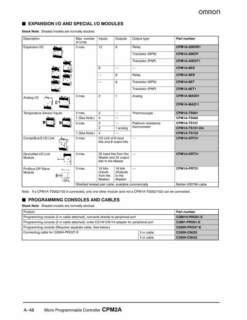
Expansion I/O Module Input
Item Specification
Input voltage 24 VDC +10%/--15%
Input impedance 4.7 kΩ
Input current 5 mA typical
ON voltage 14.4 VDC min.
OFF voltage 5.0 VDC max.
ON delay 1 to 80 ms max. Default: 10 ms (See note.)
OFF delay 1 to 80 ms max. Default: 10 ms (See note.)
Circuit configuration
4.7 kΩ
InputLED
InternalCircuits
750 Ω
Note: The input time constant can be set to 1, 2, 3, 5, 10, 20, 40, or 80 ms in the PLC Setup.
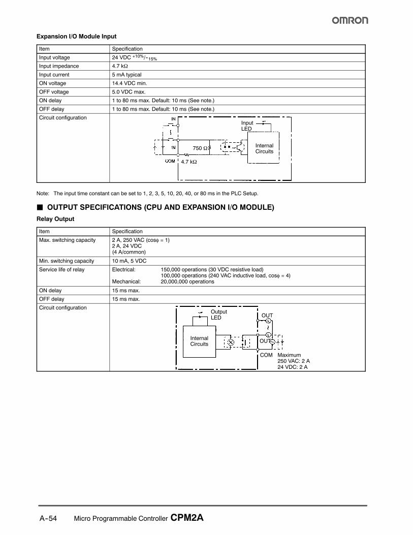
J OUTPUT SPECIFICATIONS (CPU AND EXPANSION I/O MODULE)
Relay Output
Item Specification
Max. switching capacity 2 A, 250 VAC (cosφ = 1)2 A, 24 VDC(4 A/common)
Min. switching capacity 10 mA, 5 VDC
Service life of relay Electrical: 150,000 operations (30 VDC resistive load)100,000 operations (240 VAC inductive load, cosφ = 4)
Mechanical: 20,000,000 operations
ON delay 15 ms max.
OFF delay 15 ms max.
Circuit configuration
OUT
OUT
Maximum250 VAC: 2 A24 VDC: 2 A
COM
OutputLED
InternalCircuits
A--55Micro Programmable Controller CPM2A
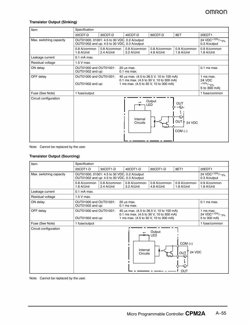
Transistor Output (Sinking)
Item Specification
20CDT-D 30CDT-D 40CDT-D 60CDT-D 8ET 20EDT1
Max. switching capacity OUT01000, 01001: 4.5 to 30 VDC, 0.2 A/outputOUT01002 and up: 4.5 to 30 VDC, 0.3 A/output
24 VDC+10%/--5%,0.3 A/output
0.8 A/common1.6 A/Unit
0.8 A/common2.4 A/Unit
0.8 A/common3.2 A/Unit
0.8 A/common4.8 A/Unit
0.9 A/common1.8 A/Unit
0.9 A/common1.8 A/Unit
Leakage current 0.1 mA max.
Residual voltage 1.5 V max.
ON delay OUT01000 and OUT01001: 20 µs max.OUT01002 and up: 0.1 ms max.
0.1 ms max.
OFF delay OUT01000 and OUT01001: 40 µs max. (4.5 to 26.5 V, 10 to 100 mA)0.1 ms max. (4.5 to 30 V, 10 to 300 mA)
OUT01002 and up: 1 ms max. (4.5 to 30 V, 10 to 300 mA)
1 ms max.24 VDC+10%/--5%,5 to 300 mA)
Fuse (See Note) 1 fuse/output 1 fuse/common
Circuit configuration
OUT
OUT
COM (--)
OutputLED
InternalCircuits 24 VDC
Note: Cannot be replaced by the user.
Transistor Output (Sourcing)
Item Specification
20CDT1-D 30CDT1-D 40CDT1-D 60CDT1-D 8ET1 20EDT1
Max. switching capacity OUT01000, 01001: 4.5 to 30 VDC, 0.2 A/outputOUT01002 and up: 4.5 to 30 VDC, 0.3 A/output
24 VDC+10%/--5%,0.3 A/output
0.8 A/common1.6 A/Unit
0.8 A/common2.4 A/Unit
0.8 A/common3.2 A/Unit
0.8 A/common4.8 A/Unit
0.9 A/common1.8 A/Unit
0.9 A/common1.8 A/Unit
Leakage current 0.1 mA max.
Residual voltage 1.5 V max.
ON delay OUT01000 and OUT01001: 20 µs max.OUT01002 and up: 0.1 ms max.
0.1 ms max.
OFF delay OUT01000 and OUT01001: 40 µs max. (4.5 to 26.5 V, 10 to 100 mA)0.1 ms max. (4.5 to 30 V, 10 to 300 mA)
OUT01002 and up: 1 ms max. (4.5 to 30 V, 10 to 300 mA)
1 ms max.24 VDC+10%/--5%,5 to 300 mA)
Fuse (See Note) 1 fuse/output 1 fuse/common
Circuit configuration
OUT
COM (+)
OutputLED
InternalCircuits 24 VDC
OUT
Note: Cannot be replaced by the user.
A--56 Micro Programmable Controller CPM2A
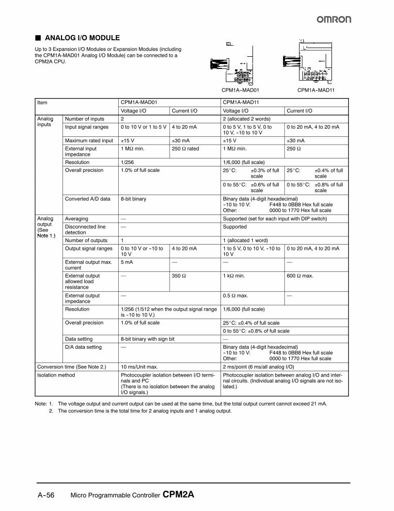
J ANALOG I/O MODULE
Up to 3 Expansion I/O Modules or Expansion Modules (includingthe CPM1A-MAD01 Analog I/O Module) can be connected to aCPM2A CPU.
CPM1A--MAD01 CPM1A--MAD11
Item CPM1A-MAD01 CPM1A-MAD11
Voltage I/O Current I/O Voltage I/O Current I/O
Analogi t
Number of inputs 2 2 (allocated 2 words)ginputs Input signal ranges 0 to 10 V or 1 to 5 V 4 to 20 mA 0 to 5 V, 1 to 5 V, 0 to
10 V, --10 to 10 V0 to 20 mA, 4 to 20 mA
Maximum rated input ±15 V ±30 mA ±15 V ±30 mA
External inputimpedance
1 MΩ min. 250 Ω rated 1 MΩ min. 250 Ω
Resolution 1/256 1/6,000 (full scale)
Overall precision 1.0% of full scale 25_C: ±0.3% of fullscale
25_C: ±0.4% of fullscale
0 to 55_C: ±0.6% of fullscale
0 to 55_C: ±0.8% of fullscale
Converted A/D data 8-bit binary Binary data (4-digit hexadecimal)--10 to 10 V: F448 to 0BB8 Hex full scaleOther: 0000 to 1770 Hex full scale
Analogt t
Averaging — Supported (set for each input with DIP switch)goutput(SeeNote 1 )
Disconnected linedetection
— Supported
Note 1.)Number of outputs 1 1 (allocated 1 word)
Output signal ranges 0 to 10 V or --10 to10 V
4 to 20 mA 1 to 5 V, 0 to 10 V, --10 to10 V
0 to 20 mA, 4 to 20 mA
External output max.current
5 mA — — —
External outputallowed loadresistance
— 350 Ω 1 kΩ min. 600 Ω max.
External outputimpedance
— 0.5 Ω max. —
Resolution 1/256 (1/512 when the output signal rangeis --10 to 10 V.)
1/6,000 (full scale)
Overall precision 1.0% of full scale 25_C: ±0.4% of full scalep
0 to 55_C: ±0.8% of full scale
Data setting 8-bit binary with sign bit —
D/A data setting — Binary data (4-digit hexadecimal)--10 to 10 V: F448 to 0BB8 Hex full scaleOther: 0000 to 1770 Hex full scale
Conversion time (See Note 2.) 10 ms/Unit max. 2 ms/point (6 ms/all analog I/O)
Isolation method Photocoupler isolation between I/O termi-nals and PC(There is no isolation between the analogI/O signals.)
Photocoupler isolation between analog I/O and inter-nal circuits. (Individual analog I/O signals are not iso-lated.)
Note: 1. The voltage output and current output can be used at the same time, but the total output current cannot exceed 21 mA.
2. The conversion time is the total time for 2 analog inputs and 1 analog output.

A--57Micro Programmable Controller CPM2A
J TEMPERATURE SENSOR MODULES
By connecting a Temperature Sensor Module(CPM1A-TS001/TS002/TS101/TS101A/TS102) to the CPM2A,inputs can be received from thermocouples or temperature-resistance thermometers. Inputs converted to binary data (4-digithexadecimal) and stored in the IR area.
Specifications
Item Specification
Model CPM1A-TS001/TS002 CPM1A-TS101/TS102 CPM1A-TS101-DA
Number of inputs TS001: 2; TS002: 4 TS101: 2; TS102: 4 2
Input types(See Note 1)
Thermocouple types K or J, selectable Platinum resistance thermometer types Pt100 and JPt1100, selectable
Input resolution 0.1°C in 2’s complement format 0.1°C in 2’s complement format
Input accuracy ±0.5% or ±2% of the stored valuewhichever is larger ±1 digit max.(See Note 2)
±0.5% or ±1% of the stored valuewhichever is larger ±1 digit max.(See Note 2)
1.0% max. full scale
Number of outputs None None 1
Output types — — Voltage or current output
Output resolution — — 1/256 (0 to 10 V)1/512 (--10 to +10 V)1/256 (4 to 20 mA)
Output accuracy — — 1.0% max. full scale
Conversion cycle 250 ms for all points 60 ms max. for all points
Convertedtemperature data
Binary data (4-digit hexadecimal) Binary data (8-digit hexadecimal)
Isolation method Photocoupler isolation between I/O terminals and the PLC
Note: 1. The same input type must be used for all inputs.
2. Accuracy for K thermocouples at temperatures less than --100°C: ±4°C ± 1 digit max.
Input Temperature Ranges
The input type is selected with a rotary switch. The ranges for each of the input types are shown in the following table.
Model CPM1A-TS001/TS002 CPM1A-TS101/TS101-DA/TS102
Input type Thermocouple type K Thermocouple type J Platinum RTD Pt100 Platinum RTD JPt100
Range in °C --200 to 1,300, 0.0 to 500.0 --100 to 850, 0.0 to 400.0 --200.0 to 650.0 --200.0 to 650.0
Range in °F --300 to 2300, 0.0 to 900.0 --100 to 1500, 0.0 to 750.0 --300.0 to 1200.0 --300.0 to 1200.0

A--58 Micro Programmable Controller CPM2A
J COMPOBUS/S I/O LINK MODULE
The CPM2A PLC can function as a Slave to a CompoBus/S Master Module (or SRM1 CompoBus/S Master Controller) when a CPM1A-SRT21 CompoBus/S I/O Link Module is connected. The CompoBus/S I/O Link Module establishes an I/O link of 8 inputs and 8 outputsbetween the Master Module and the CPM2A. Up to 3 Expansion I/O Modules or Expansion Modules can be connected to a CPM2A CPU.
CS1j, C200Hj,CQM1 (H), or SRM1 PC
Up to 16 Slaves can be connected.(Up to 8 Slaves with the CQM1-SRM21-V1.)
CompoBus/S Master Module(or SRM1 CompoBus/SMaster Controller)
CPM2A CPUCPM1A-SRT21CompoBus/S I/OLink Module
SCA1-4F10 flat cable or twisted pair Belden #9409 cable
Specifications
Item Specification
Model number CPM1A-SRT21
Master/Slave CompoBus/S Slave
Number of I/O bits 8 input bits, 8 output bits
Number of words occupied inCPM2A I/O memory
1 input word, 1 output word(Allocated in the same way as other Expansion I/O Units or Expansion Units)
Node number setting Set using the DIP switch.
Note: See the CompoBus/S section of Omron’s Remote I/O and Wiring Solutions Catalog (GC RIO1)for more details on CompoBus/Scommunications.
J CPM1A-DRT21 DEVICENET I/O LINK MODULE
The CPM1A-DRT21 DeviceNet I/O Link Module can be connected to the CPM2A to function as a slave under a DeviceNet Master Mod-ule. This enables an I/O Link with the Master Module via 32 input and 32 output points.
DeviceNet Master ModuleCPM2A CPU Module CPM1A--DRT21 DeviceNet I/O Link Module
Connect up to 63 nodes(with an CS1 Master Module)
CS1j, C200Hj, CJ1j,CV-series or CVM1PLC

A--59Micro Programmable Controller CPM2A
Specifications
Item Specification
Model number CPM1A-DRT21
Master/slave DeviceNet slave
I/O capacity to master 32 input and 32 output points
I/O memory allocated in CPM2A 2 input words and 2 output words (same as other Expansion Units)
Node address setting DIP switch (Set before turning ON power for the CPU Unit.)
Maximum number of nodes (depending on the PC to whichMaster Unit is mounted)
CS1: 63 nodesCJ1: 63 nodesCVM1/CV 32nodesC200HX/HG/HE: 25 nodesC200HS 16 nodes
J PROFIBUS-DP SLAVE MODULEThe CPM2A controller can function as a Slave to a Profibus-DP Master Module when a CPM1A-PRT21 Profibus-DP Slave Module isconnected. The Profibus-DP Slave Module establishes an I/O link of 16 inputs and 16 outputs between the master and the controller. Amaximum of 3 Profibus-DP Slave Modules can be connected to a CPM1A or CPM2A to create I/O links for up to 96 points (48 inputs and48 outputs).
Profibus-DP Master Module
PLC supporting Profibus-DP Master,e.g., CSI, C200Hj, CJ1j
Each module enablesremote I/O communica-tions for 16 inputs and16 output points as aProfibus-DP Slave.
Up to 124 nodes(using repeaters)
Shielded twisted pairBelden #3079A cable
PRT21
CPM2A CPU Module
CPM1A-PRT21 Profibus-DPSlave Module
Specifications
Storage temperature --20 to +75°C
Ambient temperature 0 to +55°C
Ambient humidity 10 to 90% (non-condensing)
EMC compliance EN 50081-2, EN 61131-2
Current consumption 100 mA from the PLC I/O bus
Weight 125 g (typical)
Control data From CPU to unit: none
Status data From unit to CPU: none
I/O data (in bytes) 2 bytes input, 2 bytes output

A--60 Micro Programmable Controller CPM2A
J COMMUNICATIONS ADAPTER
RS-232C Adapter and RS-422 AdapterCPM1--CIF01 CPM1--CIF11
Part number CPM1-CIF01 CPM1-CIF11
Functions Level conversion between the CMOS level(CPU side) and the RS-232C (peripheraldevice side)
Level conversion between the CMOS level(CPU side) and the RS-422 (peripheral deviceside)
Insulation The RS-232C (peripheral device side) is insu-lated by a DC/DC converter and photocoupler.
The RS-422 (peripheral device side) is insu-lated by a DC/DC converter and photocoupler.
Power supply Power is supplied by the CPU.
Power consumption 0.3 A max.
Transmission speed 38.4 kbits/s max.
Vibration resistance 10 to 57 Hz with an amplitude of 0.075 mm, and 57 to 150 Hz with an acceleration of 1 G in the X,Y and Z directions for 80 minutes each (i.e. for 8 minutes each, 10 times).
Shock resistance 1.5 G in the X, Y and Z directions 3 times each.
Ambient temperature Operating 0°C to 55°C (32°F to 131°F) 0°C to 55°C (32°F to 131°F)p
Storage --20°C to 75°C (--4°F to 167°F) --20°C to 75°C (--4°F to 167°F)
Ambient humidity Operating 10% to 90% RH (with no condensation)
Ambient environment Operating With no corrosive gas
Weight 200 g max.
A--61Micro Programmable Controller CPM2A
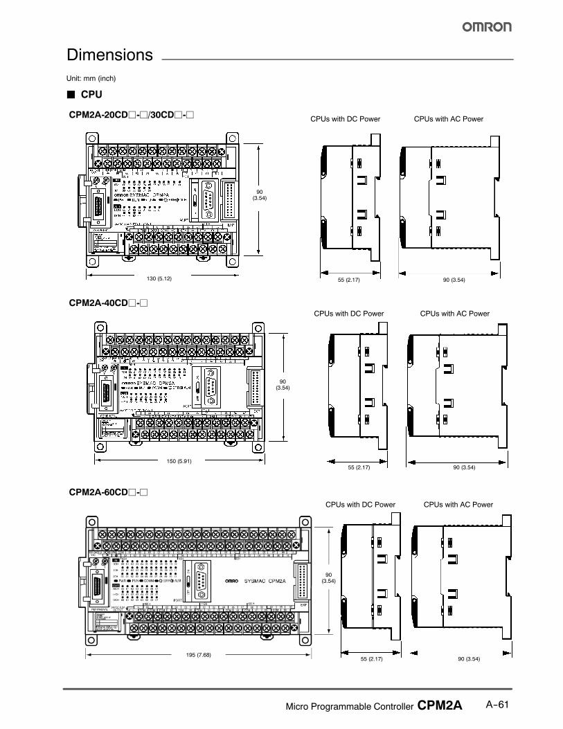
Dimensions
Unit: mm (inch)
J CPU
CPM2A-20CDj-j/30CDj-jCPUs with DC Power CPUs with AC Power
CPM2A-40CDj-jCPUs with DC Power CPUs with AC Power
CPM2A-60CDj-j
CPUs with DC Power CPUs with AC Power
90(3.54)
90(3.54)
90(3.54)
130 (5.12) 55 (2.17) 90 (3.54)
55 (2.17) 90 (3.54)
55 (2.17) 90 (3.54)195 (7.68)
150 (5.91)
A--62 Micro Programmable Controller CPM2A
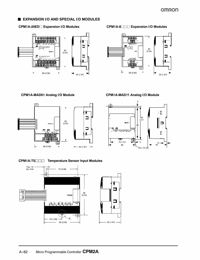
J EXPANSION I/O AND SPECIAL I/O MODULES
CPM1A-20EDj Expansion I/O Modules CPM1A-8jjj Expansion I/O Modules
CPM1A-MAD01 Analog I/O Module CPM1A-MAD11 Analog I/O Module
90(3.54)
50 (1.97)86 (3.39)
90(3.54)
50 (1.97)66 (2.60)
50 (1.97)66 (2.60)
90(3.54)
86
76 ± 0.2
Two, 4.5 dia.
5
508
5
100± 0.2
90
CPM1A-TSjjj Temperature Sensor Input Modules
86 (3.39) 50 (1.97)
43 (1.69)
73 (2.99)Two, 10dia. hole
90(3.54)
A--63Micro Programmable Controller CPM2A
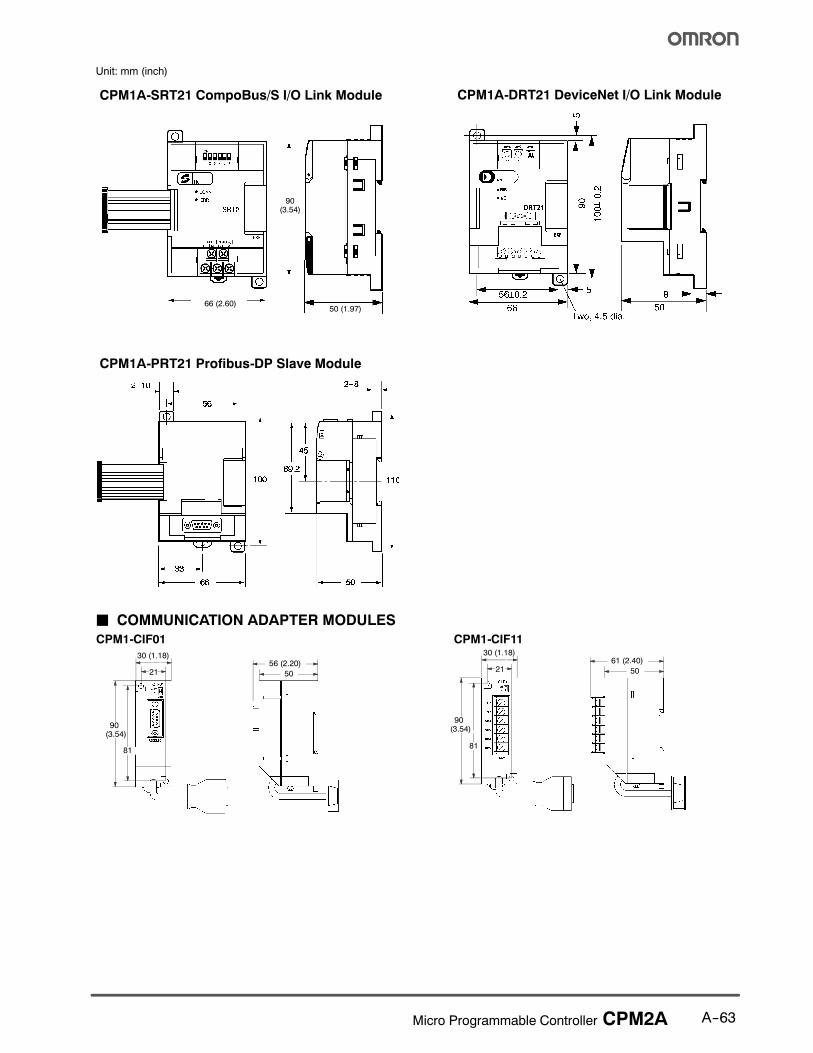
Unit: mm (inch)
CPM1A-SRT21 CompoBus/S I/O Link Module
50 (1.97)66 (2.60)
90(3.54)
CPM1A-DRT21 DeviceNet I/O Link Module
CPM1A-PRT21 Profibus-DP Slave Module
J COMMUNICATION ADAPTER MODULES
30 (1.18)
21 21
90(3.54)
81
50
56 (2.20)
81
50
61 (2.40)
CPM1-CIF01 CPM1-CIF1130 (1.18)
90(3.54)

A--64 Micro Programmable Controller CPM2A
Functions
J CONFIGURATIONThe CPM2A PLCs incorporate a variety of features, includingsynchronized pulse control, interrupt inputs, pulse outputs,analog settings, and a clock function. Use the CPM2A CPU as astand-alone controller for a broad range of machine controlapplications.
The CPM2A easily communicates with personal computers, otherOMRON PLCs, and OMRON Programmable Terminals. Thesecommunications capabilities allow the user to design a low-costdistributed production system.
The CPU contains 20, 30, 40, or 60 I/O points and Expansion I/Oblocks can be added to provide a total I/O capacity of up to 120 I/Opoints. Analog I/O modules, Temperature Sensor modules, andCompoBus/S I/O Link modules can also be connected.
Peripheral PortUse this port for programming devices (compa-tible with other OMRON PLCs) as well as HostLink and no-protocol communications.
RS-232C PortThis port can be used for a HostLink, no-protocol, 1:1 data link, or1:1 NT Link communications.
J TIME-PROPORTIONAL CONTROL
The CPM2A performs simple-to-program, time-proportionalcontrol using up to three Analog I/O modules (maximum 6 analoginputs and 3 analog outputs) and the PID and PWM expansioninstructions. These instructions set the parameters for PIDcontrol and a pulse output with variable duty ratio. For increasedreliability, an open-circuit detection function can be used with the1 to 5 VDC and 4 to 20 mA analog input settings.
For temperature monitoring applications, CPM2A accepts up to 6inputs (two per module) from Temperature Sensor Input modules.The PID instruction can manipulate the input from eitherthermocouple or platinum resistance thermometer sensors.
J DISTRIBUTED I/O CONTROL
Omron’s CompoBus/S Network provides distributed CPU controlbased on a “PLC + compact PLC” configuration which providesimprovements over distributed control based on “PLC + remoteI/O” configurations. The distributed CPU control makesequipment module, so designs can be standardized, specialneeds can be addressed and modules can be replaced easily inthe event of breakdown without affecting the main CPU.
MasterPLC
CompoBus/S Master Module
CPM2A(Slave)
CompoBus/S I/OLink Module
CompoBus/SDistributedCPU control
J BUILT-IN MOTOR CONTROL CAPABILITY
Synchronized Pulse Control (transistor output models only)
Synchronized output pulse control provides an easy way tocoordinate the operation of a peripheral piece of equipment withthe main equipment. The output pulse frequency can becontrolled as a multiple of the input pulse frequency, allowing thespeed of a peripheral piece of equipment (such as a supplyconveyor) to be synchronized with the speed of the main piece ofequipment.
Encoder CPM2A Motor
Pulses are output as a fixed multiple of the input frequency.
3G3MV Drive

A--65Micro Programmable Controller CPM2A
J HIGH-SPEED COUNTERS AND INTERRUPTS
The CPM2A has a total of five high-speed counter inputs. Theone high-speed counter input has a response frequency of20 kHz/5 kHz, and the four interrupt inputs (in counter mode)have a response frequency of 2 kHz.
Four Input Modes
The high-speed counter can be used in any one of the four inputmodes: differential phase mode (5 kHz), pulse plus direction inputmode (20 kHz), up/down pulse mode (20 kHz), or incrementmode (20 kHz). Interrupts can be triggered when the countmatches a set value or falls within a specified range.
Interrupt Inputs
The interrupt inputs (counter mode) can be used for incrementingcounters or decrementing counters (2 kHz) and trigger aninterrupt (executing the interrupt program) when the countmatches the target value. Use this for target-value comparison orrange comparison control that is unaffected by the cycle time.
Easy Position Control with Pulse Outputs(transistor output models only)
The CPM2A PLCs with transistor outputs have two outputs thatcan produce 10 Hz to 10 kHz pulses (single-phase outputs).
When used as single-phase pulse outputs, there can be twooutputs with a frequency range of 10 Hz to 10 kHz with a fixedduty ratio or 0.1 to 999.9 Hz with a variable duty ratio (0 to 100%duty ratio).
When used as pulse plus direction or up/down pulse outputs,there can be just one output with a frequency range of 10 Hz to10 kHz.
Counter inputs
Reset inputs (for differential phase inputs)
SensorRotary encoder(such as E6C2-C)
Input Response frequency Input mode (count value) Control method
0000000001
5 kHz Differential phase input mode (-8,388,608 to 8,388,607) Target value comparison interruptsR i i t t00001
0000220 kHz Pulse + direction input mode (-8,388,608 to 8,388,607)
Up/down pulse input mode (-8,388,608 to 8,388,607)Increment mode (0 to 16,777,215)
g p pRange comparison interrupts
A--66 Micro Programmable Controller CPM2A
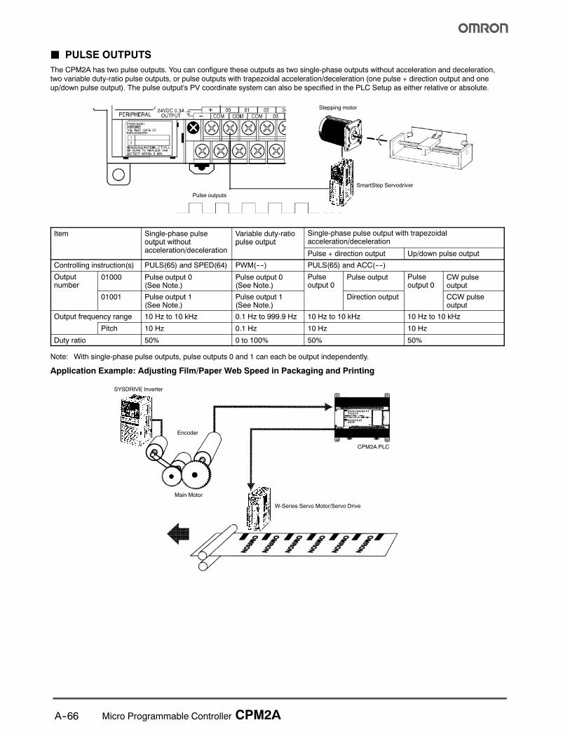
J PULSE OUTPUTS
The CPM2A has two pulse outputs. You can configure these outputs as two single-phase outputs without acceleration and deceleration,two variable duty-ratio pulse outputs, or pulse outputs with trapezoidal acceleration/deceleration (one pulse + direction output and oneup/down pulse output). The pulse output’s PV coordinate system can also be specified in the PLC Setup as either relative or absolute.
Stepping motor
Pulse outputs
SmartStep Servodriver
Item Single-phase pulseoutput without
l i /d l i
Variable duty-ratiopulse output
Single-phase pulse output with trapezoidalacceleration/decelerationoutput t out
acceleration/decelerationpu se output
Pulse + direction output Up/down pulse output
Controlling instruction(s) PULS(65) and SPED(64) PWM(----) PULS(65) and ACC(----)
Outputnumber
01000 Pulse output 0(See Note.)
Pulse output 0(See Note.)
Pulseoutput 0
Pulse output Pulseoutput 0
CW pulseoutputu be
01001 Pulse output 1(See Note.)
Pulse output 1(See Note.)
ou pu 0
Direction output
ou pu 0
CCW pulseoutput
Output frequency range 10 Hz to 10 kHz 0.1 Hz to 999.9 Hz 10 Hz to 10 kHz 10 Hz to 10 kHz
Pitch 10 Hz 0.1 Hz 10 Hz 10 Hz
Duty ratio 50% 0 to 100% 50% 50%
Note: With single-phase pulse outputs, pulse outputs 0 and 1 can each be output independently.
Application Example: Adjusting Film/Paper Web Speed in Packaging and Printing
CPM2A PLC
Main Motor
Encoder
SYSDRIVE Inverter
W-Series Servo Motor/Servo Drive

A--67Micro Programmable Controller CPM2A
J HIGH-SPEED INPUT CAPABILITIES FORMACHINE CONTROL
High-speed Interrupt Input Function
There are four inputs used for interrupt inputs (shared with quick-response inputs and interrupt inputs in counter mode) with aminimum input signal width of 50 µs and a response time of0.3 ms. When an interrupt input goes ON, the main program isstopped and the interrupt program is executed.
Quick-response Input Function
There are four inputs used for quick-response inputs (shared withinterrupt inputs and interrupt inputs in counter mode) that canreliably read input signals with a signal width as short as 50 µs.Quick-response inputs are received into an internal buffer, sosignals that change status within a cycle can be processed.
Stabilizing Input Filter Function
The input time constant for all inputs can be set to 1 ms, 2 ms,3 ms, 5 ms, 10 ms, 20 ms, 40 ms, or 80 ms. The effects ofchattering and external noise can be reduced by increasing theinput time constant.
Interval Timer Interrupts
The interval timer offers a 0.5 and 319,968 ms range and can beset to generate just one interrupt (one-shot mode) or periodicinterrupts (scheduled interrupt mode) to match the application.
J OTHER FUNCTIONS
Analog Settings
There are two controls on the CPU that can be turned to changethe analog settings (0 to 200 BCD) of timers and counters. Thesecontrols can be used to easily change or fine-tune machinesettings such as a conveyor belt’s pause time or feed rate.
Calendar/Clock
The built-in clock (accuracy within 1 minute/month) can be readfrom the program to show the current year, month, day, day of theweek, and time. The clock can be set from a programming device(such as a Programming Console) or the time can be adjusted by
rounding up or down to the nearest minute.
Long-term Timer
The long-term timer provides an easy way to control equipmentscheduling. Use two instructions to set this up. The long-termtimer instruction (TIML) lets you set values up to 99,990 seconds(27 hours, 46 minutes, 30 seconds) and the Seconds-to-Hoursconversion instruction (HMS) lets you schedule this with otherclock functions.
Communications
J NT LINK FOR PROGRAMMABLE TERMINALS
The CPM2A can be connected directly to an OMRON NT-Series Programmable Terminal in NT Link mode (1:1) for high-speed transmis-sion of data. No separate drivers are required Use the RS-232C port for the NT Link connection.
Serial Port
PeripheralPort
Operator InterfaceTerminal
CBL-804*CBL-803*C200H-CN_0-EU,NT31C-CN_0-EU,
(for NT31C Port B only)
* Available in Canada only.
A--68 Micro Programmable Controller CPM2A
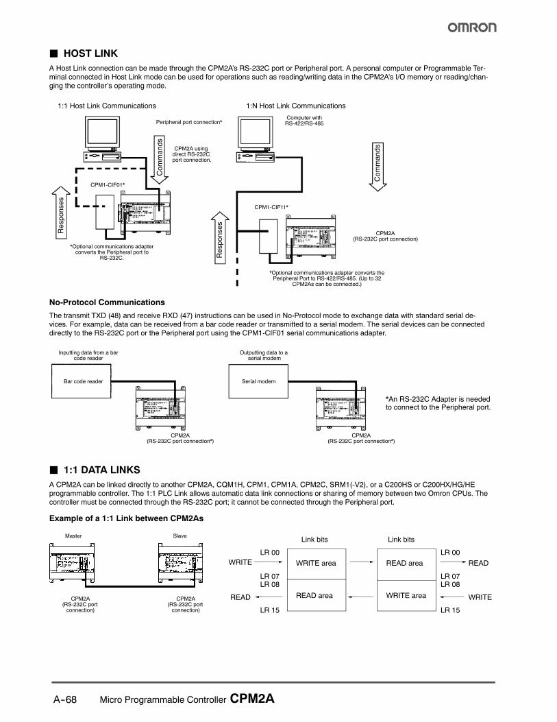
J HOST LINK
A Host Link connection can be made through the CPM2A’s RS-232C port or Peripheral port. A personal computer or Programmable Ter-minal connected in Host Link mode can be used for operations such as reading/writing data in the CPM2A’s I/O memory or reading/chan-ging the controller’s operating mode.
1:1 Host Link Communications
CPM1-CIF01*
CPM2A usingdirect RS-232Cport connection.
*Optional communications adapterconverts the Peripheral port to
RS-232C.
1:N Host Link Communications
CPM2A(RS-232C port connection)
*Optional communications adapter converts thePeripheral Port to RS-422/RS-485. (Up to 32
CPM2As can be connected.)
Commands
Responses
Commands
Responses
Computer withRS-422/RS-485Peripheral port connection*
CPM1-CIF11*
No-Protocol Communications
The transmit TXD (48) and receive RXD (47) instructions can be used in No-Protocol mode to exchange data with standard serial de-vices. For example, data can be received from a bar code reader or transmitted to a serial modem. The serial devices can be connecteddirectly to the RS-232C port or the Peripheral port using the CPM1-CIF01 serial communications adapter.
CPM2A(RS-232C port connection*)
Inputting data from a barcode reader
Bar code reader
CPM2A(RS-232C port connection*)
Outputting data to aserial modem
Serial modem
*An RS-232C Adapter is neededto connect to the Peripheral port.
J 1:1 DATA LINKS
A CPM2A can be linked directly to another CPM2A, CQM1H, CPM1, CPM1A, CPM2C, SRM1(-V2), or a C200HS or C200HX/HG/HEprogrammable controller. The 1:1 PLC Link allows automatic data link connections or sharing of memory between two Omron CPUs. Thecontroller must be connected through the RS-232C port; it cannot be connected through the Peripheral port.
Example of a 1:1 Link between CPM2As
Link bits
WRITE area
READ area
LR 00
LR 07LR 08
LR 15
WRITE
READ
READ area
WRITE area
LR 00
LR 07LR 08
LR 15
READ
WRITE
Link bitsMaster Slave
CPM2A(RS-232C portconnection)
CPM2A(RS-232C portconnection)

A--69Micro Programmable Controller CPM2A
J PROGRAM TRANSFER UNIT
Use Omron’s EEPROM program transfer unit to update programs in machines or program multiple controllers with the same program.The CPM1-EMU01-V1 Expansion Memory Unit connects to the peripheral port of micro and small PLCs.
Uploading
Downloading
EEPROM
Omron SRM1, CPM1A, CPM2A,CPM2B, CPM2C and CQM1Hprogrammable controllers

! ! "! # # ! $ %& ''(% %%) * + !! #
! %) % *
, - ( ! ! # * ! . !% # + *
/ 011 %2 $# # * % % ! %
## !%# # 3 " $
4 . . ! # . ! ! 3 % % !! ! # !! $ ! . ! ! # . % %*
5 67 * % ! # 3 # 7* 8 ! % $ $* !"% ! ! %* * # %
9 ( & %) * .
: 6 ;) % % # % ! 38 ! !!8 % ! % ! ! % ! ! 8 3 #
1 - # < . % = % % % % * #
# * $% 6* "
% ! 8 $ * !# $ %*
- # 8 $
. ( % *
$% # % ,1 "% % # $
> &.# > + .# $% 8 # % . % ! . % '&''&?;@&A>??AB??&?&&A7A!&C?&? 7;'7&-!*<AA"7A6?7A$&;&A!;&?(DA*7'"7B ? 67A& 6? ?7(<'? <?& 6 D& $-*<B&?(@A>'&-$&D7'A&D-&&?;7A&-DD&$- >7'' <7*'B ;&& D& ?&E<7?&;&A 6 D&7?7A&A-&-<& % . % % $ " * ? + %" % * % % # "$! + ! * 3 $# # % % ! ! . $ + $ ! ! %) "!% ! ? %* % # % % % % %% $% !! % % # # ! # ! % %#
, - '&&''&?D''A*&'7*'&6?&(7'!7A-7"?&( ? (A&E<&A7' -;$&! ' 6 ?67 ? ?"-<(7A?(;;&?(7''7AAB>B(AA&(&->7DD&$-!>D&D&?<(D('7;7*&-7A(A?(!>??AB!A&$'7$&A(&??7('7*7'7B 6 ! # % . # $%
/ 7 * ! % ! ! ! . + . !# "! * + $> !* . % . % $ *
2 ( % $ .# * A" * ! .# % * $ " ! * % #
4; ># A % . % * # % % * + % * $!"#% # % # %7# # #!## # * # # !
%< % % "! % $ * + $* + 3 ! # % $% % $ % ! ! ! . % # % .# % $! % % $= ! ##
! % & !% ! !#
! 3 ! !# ! 3 !%) #
! 3 8 8% # % % $
A&F&?<&D&?-<(6?A'7(7A7AF'F7A$&?7<?7@'76&??&?B>7D<&A<?7A$DD&B&;>D'&D*&&A-&7$A&---?&D&?7@!A-DD& &''&?+ ?-<( 7 ?&?'B ?&- A- 7A''&- 6?D&7A&A-&-<&>7D7AD&F&?''&E<7;&A?B&;
% % % + "% $! 3
, - # # % 7 + ! " 3 %) +>''%
/ ( % % # 7" % % ! D # ! " $% > %! % % . %8 + # $
2 & % 8 % # % # ! % ! !
$%"=GG<"=GGG ("=GG
Cat. No. R301-E3-01 2/04 Specifications subject to change without notice Printed in USA
! "#992; # !;*2F9
$%&'&&$&(
( -# %!7'415,
$)$*)+,,6< 3 =
,,((&&)&&
- ./ 012
111# # 3H/- 2.2"/4#
!56 ## !%11,:,5# !%11,25