Micro Mill Tilting Spindle, Increased Y-axis Travel Kit · 2018-03-20 · Micro Mill Tilting...
12
Updated 12/21/2006 © 2004 LittleMachineShop.com Page 1 The premier source of parts and accessories for mini lathes and mini mills. Micro Mill Tilting Spindle, Increased Y-axis Travel Kit This kit increases the Y-axis travel to 130 mm and adds the capability to tilt the spindle 45° in either direction. To install the Kit you disassemble your micro mill and reassemble it with the new parts. The kit includes the following parts: Parts Diagram Number Quantity 2296 Part 101 1 Column cover 102A 1 Column 114A 1 Saddle 141 1 Y-axis feed screw 142 1 Y-axis gib 143 1 Pivot housing 144 1 Pivot 145 1 Pivot lock ring 166 1 Y-axis nut 74A 1 Base casting 1 Z-axis scale 1 Scale pointer 2 Escutcheon pins 8 M4 nuts 8 M4x18 socket dog point setscrew 2 M4x20 socket head cap screw 1 M6x6 round head Phillips machine screw 4 M6x25 socket head cap screw 8 M8x25 socket head cap screw 4 M8 lock washer
Transcript of Micro Mill Tilting Spindle, Increased Y-axis Travel Kit · 2018-03-20 · Micro Mill Tilting...
Updated 12/21/2006 © 2004 LittleMachineShop.com Page 1
The premier source of parts and accessories for mini lathes and mini mills.
Micro Mill Tilting Spindle, Increased Y-axis Travel Kit This kit increases the Y-axis travel to 130 mm and adds the capability to tilt the spindle 45° in either direction. To install the Kit you disassemble your micro mill and reassemble it with the new parts. The kit includes the following parts:
Parts Diagram Number Quantity
2296 Part
101 1 Column cover
102A 1 Column
114A 1 Saddle
141 1 Y-axis feed screw
142 1 Y-axis gib
143 1 Pivot housing
144 1 Pivot
145 1 Pivot lock ring
166 1 Y-axis nut
74A 1 Base casting
1 Z-axis scale
1 Scale pointer
2 Escutcheon pins
8 M4 nuts
8 M4x18 socket dog point setscrew
2 M4x20 socket head cap screw
1 M6x6 round head Phillips machine screw
4 M6x25 socket head cap screw
8 M8x25 socket head cap screw
4 M8 lock washer
Updated 12/21/2006 © 2004 LittleMachineShop.com Page 2
Parts Diagram Number Quantity
2296 Part
4 M8 flat washer
4 M8x30 cap screw
4 M4x8 socket head cap screw
You will need the following tools and materials: Hex (Allen) wrenches (3, 5, and 6 mm) End wrenches (7, 8, 10, and 14 mm) #2 Phillips screw driver Small straight-blade screwdriver Side cutting pliers (dikes) Fine file Soft-faced hammer M5x0.75 metric tap M6x1 metric tap M8x1.25 metric tap Prick punch and center punch #3 center drill Hammer Machinist's square Wooden block, such as a piece of 2x4 about 8” long. Engine assembly lube Mobil 1 synthetic oil (any viscosity)
Expect to spend between two and four hours on this project. If you do not understand what a part is that is referenced in these instructions, see the manufacturer’s parts diagram in the Instruction Manual that came with the micro mill. In the following procedures, left, right, front, and back are always related to the operator’s position at the micro mill. The X-axis provides motion from side to side, the Y-axis provides motion from front to back, and the Z-axis provides motion up and down.
Teardown Follow this procedure to disassemble your micro mill. 1. Unplug the power cord.
Updated 12/21/2006 © 2004 LittleMachineShop.com Page 3
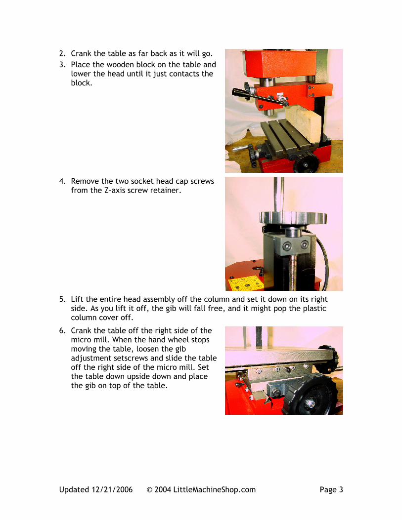
2. Crank the table as far back as it will go. 3. Place the wooden block on the table and
lower the head until it just contacts the block.
4. Remove the two socket head cap screws from the Z-axis screw retainer.
5. Lift the entire head assembly off the column and set it down on its right side. As you lift it off, the gib will fall free, and it might pop the plastic column cover off.
6. Crank the table off the right side of the micro mill. When the hand wheel stops moving the table, loosen the gib adjustment setscrews and slide the table off the right side of the micro mill. Set the table down upside down and place the gib on top of the table.
Updated 12/21/2006 © 2004 LittleMachineShop.com Page 4
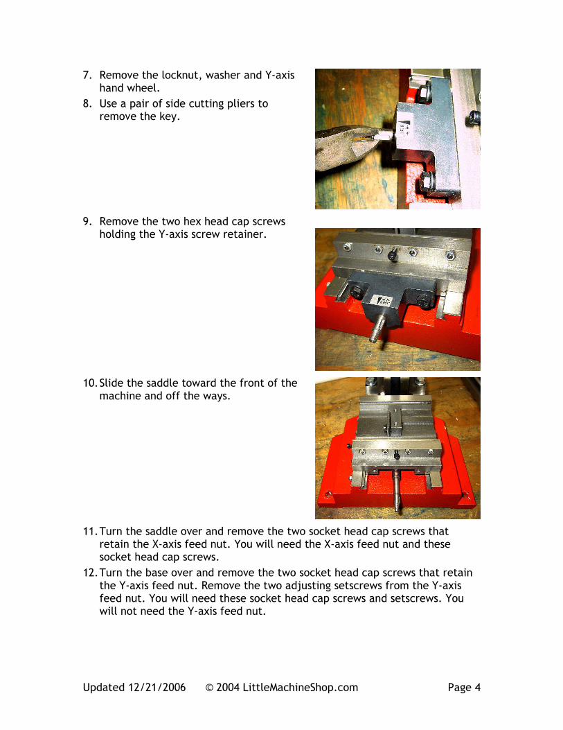
7. Remove the locknut, washer and Y-axis hand wheel.
8. Use a pair of side cutting pliers to remove the key.
9. Remove the two hex head cap screws holding the Y-axis screw retainer.
10. Slide the saddle toward the front of the machine and off the ways.
11. Turn the saddle over and remove the two socket head cap screws that retain the X-axis feed nut. You will need the X-axis feed nut and these socket head cap screws.
12. Turn the base over and remove the two socket head cap screws that retain the Y-axis feed nut. Remove the two adjusting setscrews from the Y-axis feed nut. You will need these socket head cap screws and setscrews. You will not need the Y-axis feed nut.
Updated 12/21/2006 © 2004 LittleMachineShop.com Page 5
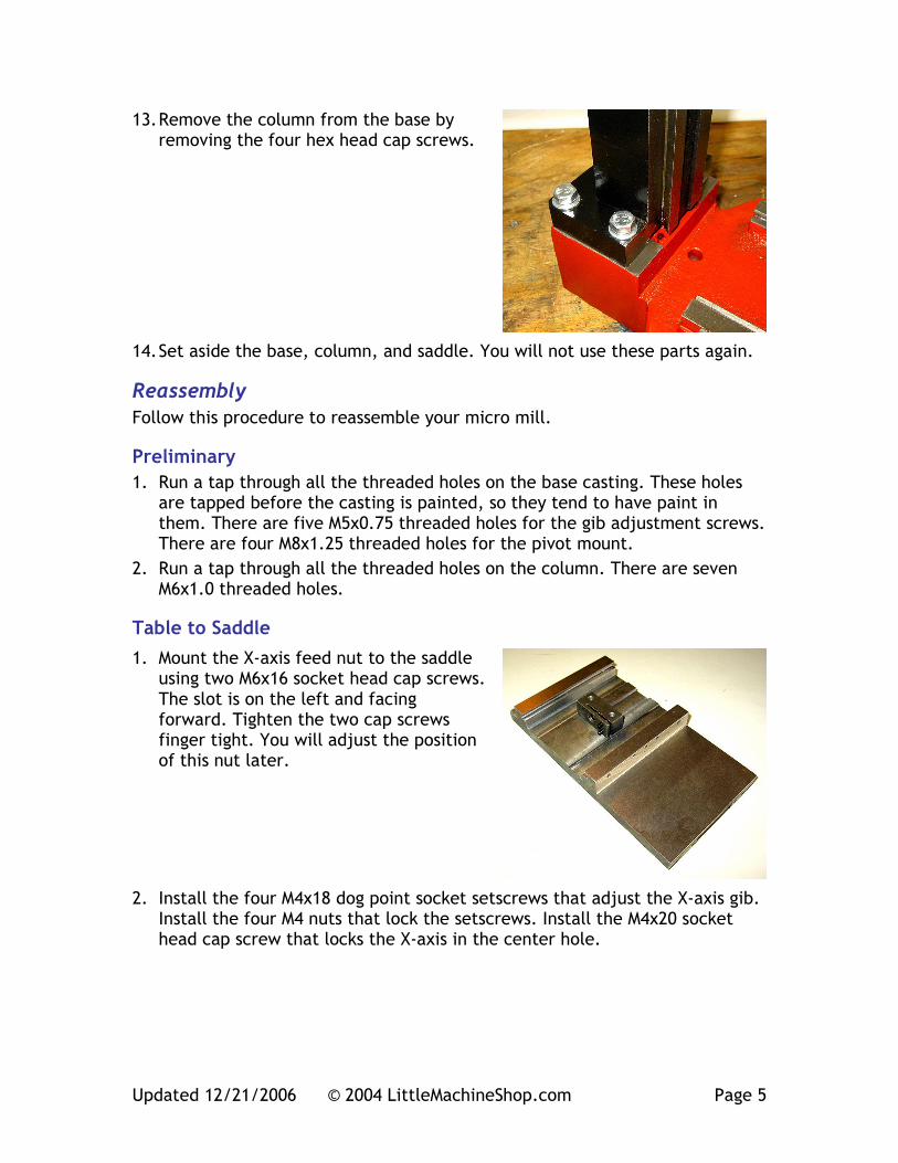
13. Remove the column from the base by removing the four hex head cap screws.
14. Set aside the base, column, and saddle. You will not use these parts again.
Reassembly Follow this procedure to reassemble your micro mill.
Preliminary 1. Run a tap through all the threaded holes on the base casting. These holes
are tapped before the casting is painted, so they tend to have paint in them. There are five M5x0.75 threaded holes for the gib adjustment screws. There are four M8x1.25 threaded holes for the pivot mount.
2. Run a tap through all the threaded holes on the column. There are seven M6x1.0 threaded holes.
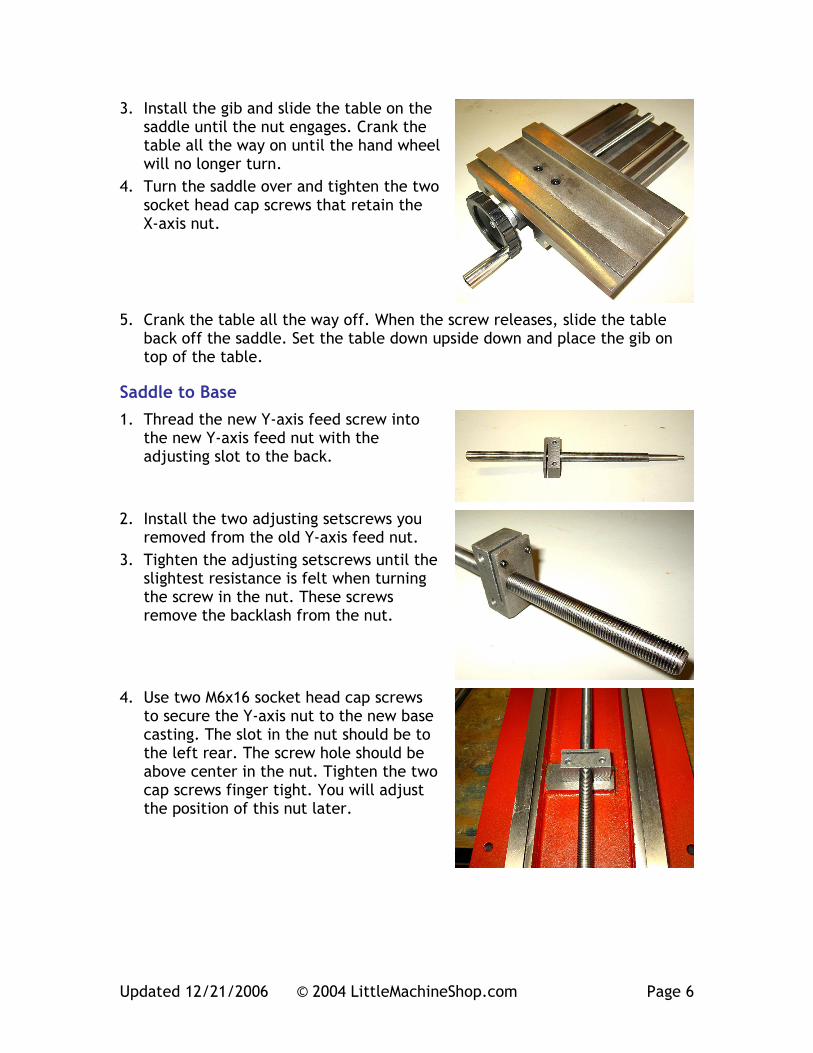
Table to Saddle 1. Mount the X-axis feed nut to the saddle
using two M6x16 socket head cap screws. The slot is on the left and facing forward. Tighten the two cap screws finger tight. You will adjust the position of this nut later.
2. Install the four M4x18 dog point socket setscrews that adjust the X-axis gib. Install the four M4 nuts that lock the setscrews. Install the M4x20 socket head cap screw that locks the X-axis in the center hole.
Updated 12/21/2006 © 2004 LittleMachineShop.com Page 6
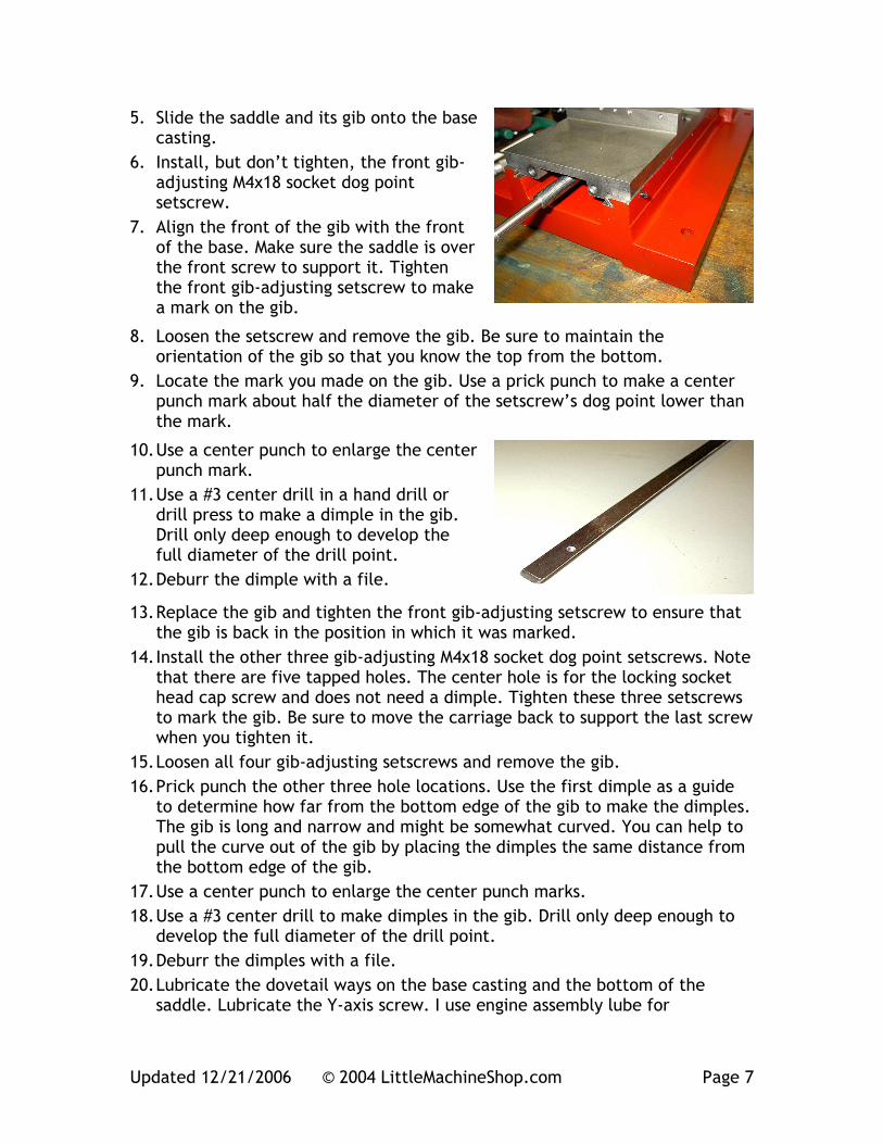
3. Install the gib and slide the table on the saddle until the nut engages. Crank the table all the way on until the hand wheel will no longer turn.
4. Turn the saddle over and tighten the two socket head cap screws that retain the X-axis nut.
5. Crank the table all the way off. When the screw releases, slide the table back off the saddle. Set the table down upside down and place the gib on top of the table.
Saddle to Base 1. Thread the new Y-axis feed screw into
the new Y-axis feed nut with the adjusting slot to the back.
2. Install the two adjusting setscrews you removed from the old Y-axis feed nut.
3. Tighten the adjusting setscrews until the slightest resistance is felt when turning the screw in the nut. These screws remove the backlash from the nut.
4. Use two M6x16 socket head cap screws to secure the Y-axis nut to the new base casting. The slot in the nut should be to the left rear. The screw hole should be above center in the nut. Tighten the two cap screws finger tight. You will adjust the position of this nut later.
Updated 12/21/2006 © 2004 LittleMachineShop.com Page 7
5. Slide the saddle and its gib onto the base casting.
6. Install, but don’t tighten, the front gib-adjusting M4x18 socket dog point setscrew.
7. Align the front of the gib with the front of the base. Make sure the saddle is over the front screw to support it. Tighten the front gib-adjusting setscrew to make a mark on the gib.
8. Loosen the setscrew and remove the gib. Be sure to maintain the orientation of the gib so that you know the top from the bottom.
9. Locate the mark you made on the gib. Use a prick punch to make a center punch mark about half the diameter of the setscrew’s dog point lower than the mark.
10. Use a center punch to enlarge the center punch mark.
11. Use a #3 center drill in a hand drill or drill press to make a dimple in the gib. Drill only deep enough to develop the full diameter of the drill point.
12. Deburr the dimple with a file.
13. Replace the gib and tighten the front gib-adjusting setscrew to ensure that the gib is back in the position in which it was marked.
14. Install the other three gib-adjusting M4x18 socket dog point setscrews. Note that there are five tapped holes. The center hole is for the locking socket head cap screw and does not need a dimple. Tighten these three setscrews to mark the gib. Be sure to move the carriage back to support the last screw when you tighten it.
15. Loosen all four gib-adjusting setscrews and remove the gib. 16. Prick punch the other three hole locations. Use the first dimple as a guide
to determine how far from the bottom edge of the gib to make the dimples. The gib is long and narrow and might be somewhat curved. You can help to pull the curve out of the gib by placing the dimples the same distance from the bottom edge of the gib.
17. Use a center punch to enlarge the center punch marks. 18. Use a #3 center drill to make dimples in the gib. Drill only deep enough to
develop the full diameter of the drill point. 19. Deburr the dimples with a file. 20. Lubricate the dovetail ways on the base casting and the bottom of the
saddle. Lubricate the Y-axis screw. I use engine assembly lube for
Updated 12/21/2006 © 2004 LittleMachineShop.com Page 8
applications like this. It is a mixture of grease and oil that stays in place well.
21. Slide the saddle into place on the base casting dovetail ways.
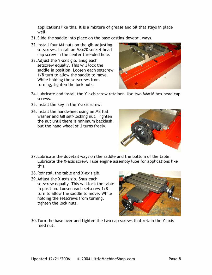
22. Install four M4 nuts on the gib-adjusting setscrews. Install an M4x20 socket head cap screw in the center threaded hole.
23. Adjust the Y-axis gib. Snug each setscrew equally. This will lock the saddle in position. Loosen each setscrew 1/8 turn to allow the saddle to move. While holding the setscrews from turning, tighten the lock nuts.
24. Lubricate and install the Y-axis screw retainer. Use two M6x16 hex head cap screws.
25. Install the key in the Y-axis screw.
26. Install the handwheel using an M8 flat washer and M8 self-locking nut. Tighten the nut until there is minimum backlash, but the hand wheel still turns freely.
27. Lubricate the dovetail ways on the saddle and the bottom of the table. Lubricate the X-axis screw. I use engine assembly lube for applications like this.
28. Reinstall the table and X-axis gib. 29. Adjust the X-axis gib. Snug each
setscrew equally. This will lock the table in position. Loosen each setscrew 1/8 turn to allow the saddle to move. While holding the setscrews from turning, tighten the lock nuts.
30. Turn the base over and tighten the two cap screws that retain the Y-axis feed nut.
Updated 12/21/2006 © 2004 LittleMachineShop.com Page 9
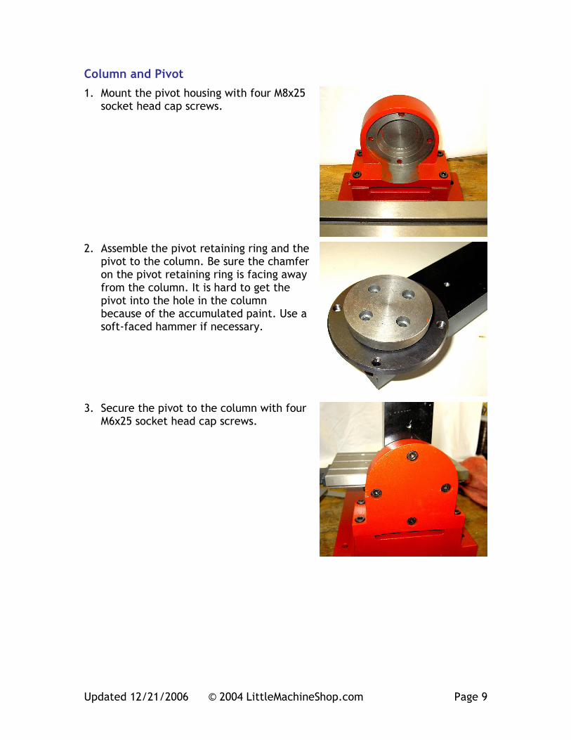
Column and Pivot 1. Mount the pivot housing with four M8x25
socket head cap screws.
2. Assemble the pivot retaining ring and the pivot to the column. Be sure the chamfer on the pivot retaining ring is facing away from the column. It is hard to get the pivot into the hole in the column because of the accumulated paint. Use a soft-faced hammer if necessary.
3. Secure the pivot to the column with four M6x25 socket head cap screws.
Updated 12/21/2006 © 2004 LittleMachineShop.com Page 10
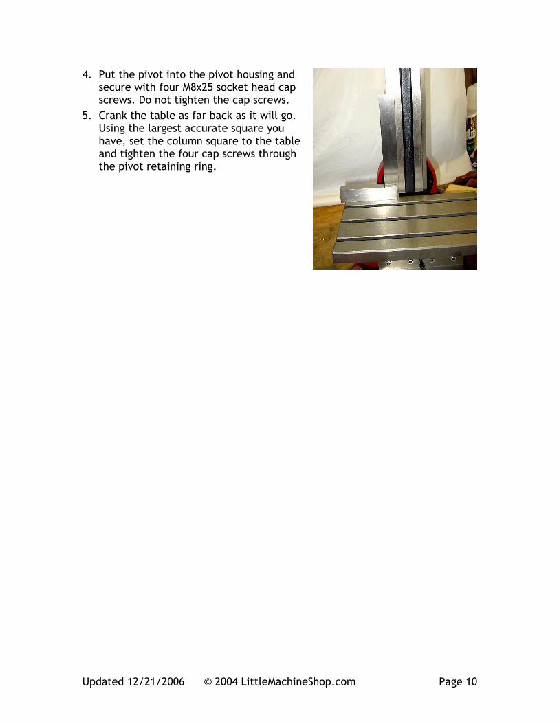
4. Put the pivot into the pivot housing and secure with four M8x25 socket head cap screws. Do not tighten the cap screws.
5. Crank the table as far back as it will go. Using the largest accurate square you have, set the column square to the table and tighten the four cap screws through the pivot retaining ring.
Updated 12/21/2006 © 2004 LittleMachineShop.com Page 11
4. Place the wooden block on the table.
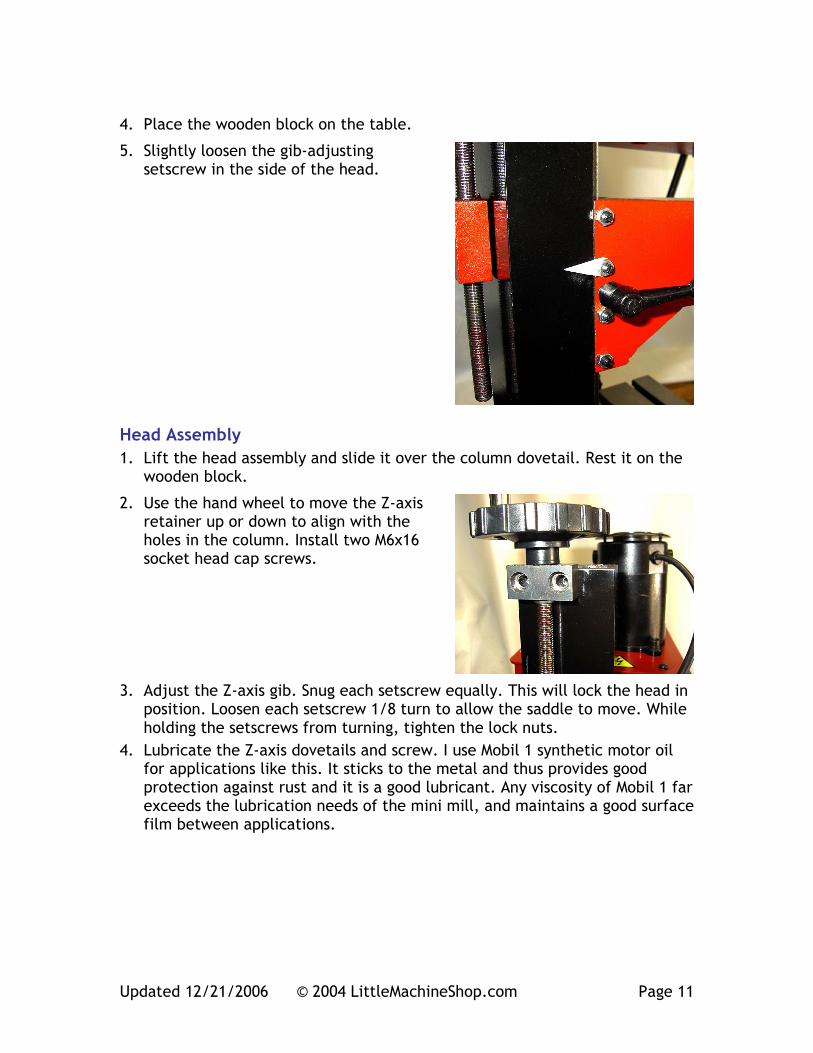
5. Slightly loosen the gib-adjusting setscrew in the side of the head.
Head Assembly 1. Lift the head assembly and slide it over the column dovetail. Rest it on the
wooden block.
2. Use the hand wheel to move the Z-axis retainer up or down to align with the holes in the column. Install two M6x16 socket head cap screws.
3. Adjust the Z-axis gib. Snug each setscrew equally. This will lock the head in position. Loosen each setscrew 1/8 turn to allow the saddle to move. While holding the setscrews from turning, tighten the lock nuts.
4. Lubricate the Z-axis dovetails and screw. I use Mobil 1 synthetic motor oil for applications like this. It sticks to the metal and thus provides good protection against rust and it is a good lubricant. Any viscosity of Mobil 1 far exceeds the lubrication needs of the mini mill, and maintains a good surface film between applications.
Updated 12/21/2006 © 2004 LittleMachineShop.com Page 12
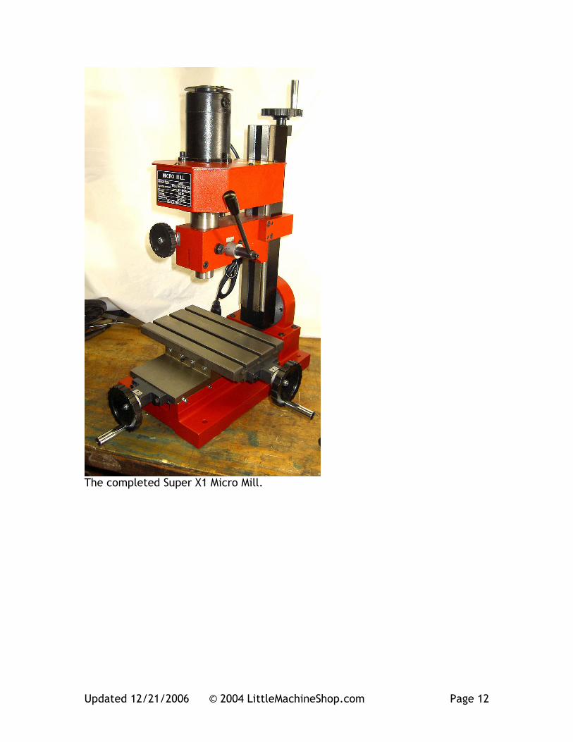
The completed Super X1 Micro Mill.