MICRO-CAP 10 - Spectrum · PDF file · 2010-03-18to build SPICE text file circuits....
8
MICRO-CAP 10 Analog/Digital Simulator INDUSTRIAL-STRENGTH SIMULATION
Transcript of MICRO-CAP 10 - Spectrum · PDF file · 2010-03-18to build SPICE text file circuits....
MICRO-CAP 10Analog/Digital Simulator
I N D U S T R I A L - S T R E N G T H S I M U L A T I O N
� � � � � � � � � � � � � � � � � � � � � � � � � � � � � � � � � � � � � � � � � � � � � � � � � � � � � � � � � � � � � � � � � � � � � � � � � � � � � � � � � � � � � � � � � � � � � � � � � � � � � � � � � � � � � � � � � � � � � � � � � � � � � � � � � � � � � � � � � � � � � � � � � � �� � � � � � � � � � � � � � � � � � � � � � � � � � � � � � � � � � � � � � � � � � � � � � � � � � � � �� � � � � � � � � � � � � � � � � � � � � � � � � � � � � � � � � � � � � � � � � �
Micro-Cap 10 is an integrated schematic editor and mixed analog / digital simulatorthat provides an interactive sketch and simulate environment for electronics engineers. It has seen ten generations of refinement since its release in 1982. It blends a modern,intuitive interface with robust numerical algorithms to produce unparalleled levels of simulation power and ease of use.
FastAlgorithmic improvements, optimized code, and an integrated interface contributeto the stunning speed of Micro-Cap 10.
PowerfulNumerous features contribute to the power of Micro-Cap 10:� Multi-page hierarchical schematic editor� PSpiceTM, SPICE3, and many HSPICETM commands and models supported� Threading support for multiple CPUs and faster simulations� Native digital simulation engine� Periodic Steady State analysis� Integral circuit optimizer with multiple optimization methods� Harmonic and intermodulation distortion analysis� Integrated active and passive filter design function� Device library with over 24,000 parts� Analog and digital behavioral modeling� Schematic waveform probing� On-schematic voltage/state, current, power, and condition display� Dynamic analysis updates waveforms and curves as you edit� During the run plotting� Smith charts / polar plots� Multidimensional parameter stepping� Monte Carlo analysis� 3D plotting� Performance functions and plots� Optimizing parts modeler� Gummel-Poon, Mextram and Modella bipolar models� Berkeley BSIM1, BSIM2, BSIM3, and BSIM4 MOSFET models� The latest Philips device models, including MOS 11, 20, 31, 40, and PSP 102� EKV V2.6 MOSFET model� Hefner IGBT model� IBIS model translator� Animated LEDs, switches, bars, meters, relays, stoplights, and DC motors� Sample and hold, timer, and Z transform devices� Lossy transmission lines� Jiles-Atherton nonlinear magnetics model� PCB interface to popular packages� LAN version for collaborative projects
Easy to useThe graphical, user-friendly interface is simple to learn and use. Familiar SPICEmodels, plus extensions, are easy to apply. Over 500 warnings and messages helpyou through problems, when the error occurs, not later in a text file.
AffordableYou can easily spend two to five times the cost of Micro-Cap 10 for other simulatorswithout matching its power, speed, and ease of use.
GuaranteedMicro-Cap 10 comes with a full, unconditional, 30 day money-back guarantee.
Micro-Cap 10... Ten Generations of Refinement
in CircuitSimulation
� �
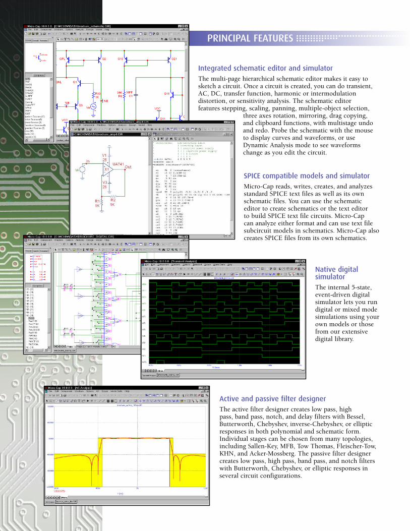
Integrated schematic editor and simulatorThe multi-page hierarchical schematic editor makes it easy tosketch a circuit. Once a circuit is created, you can do transient,AC, DC, transfer function, harmonic or intermodulation distortion, or sensitivity analysis. The schematic editor features stepping, scaling, panning, multiple-object selection,
three axes rotation, mirroring, drag copying, and clipboard functions, with multistage undo and redo. Probe the schematic with the mouse to display curves and waveforms, or useDynamic Analysis mode to see waveformschange as you edit the circuit.
SPICE compatible models and simulatorMicro-Cap reads, writes, creates, and analyzesstandard SPICE text files as well as its ownschematic files. You can use the schematic editor to create schematics or the text editor to build SPICE text file circuits. Micro-Cap can analyze either format and can use text file subcircuit models in schematics. Micro-Cap alsocreates SPICE files from its own schematics.
Native digital simulatorThe internal 5-state,event-driven digital simulator lets you rundigital or mixed modesimulations using yourown models or thosefrom our extensive digital library.
Active and passive filter designerThe active filter designer creates low pass, high pass, band pass, notch, and delay filters with Bessel,Butterworth, Chebyshev, inverse-Chebyshev, or ellipticresponses in both polynomial and schematic form.Individual stages can be chosen from many topologies,including Sallen-Key, MFB, Tow Thomas, Fleischer-Tow,KHN, and Acker-Mossberg. The passive filter designercreates low pass, high pass, band pass, and notch filterswith Butterworth, Chebyshev, or elliptic responses inseveral circuit configurations.
PRINCIPAL FEATURES � � � � � � � � � � � � � � � � � � � � � � � � � � � � � � � � � � � � � � � � �� � � � � � � � � � � � � � �� � � � � � � � � �
� � � � � � � � � � � � � � � � � � � � � � � � � � � � � � � � �� � � � � � � � � � � � � � �� � � � � � � � � �
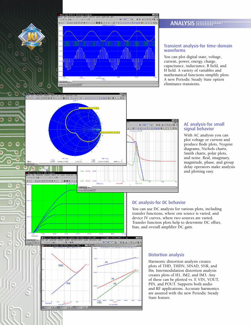
Transient analysis-for time-domainwaveformsYou can plot digital state, voltage, current, power, energy, charge, capacitance, inductance, B field, and H field. A variety of variables and mathematical functions simplify plots.A new Periodic Steady State optioneliminates transients.
ANALYSIS
AC analysis-for small signal behaviorWith AC analysis you canplot voltage or current andproduce Bode plots, Nyquistdiagrams, Nichols charts,Smith charts, polar plots, and noise. Real, imaginary,magnitude, phase, and groupdelay operators make analysis and plotting easy.
DC analysis-for DC behaviorYou can use DC analysis for various plots, includingtransfer functions, where one source is varied, anddevice IV curves, where two sources are varied. Transfer function plots help to determine DC offset,bias, and overall amplifier DC gain.
Distortion analysis
Harmonic distortion analysis createsplots of THD, THDN, SINAD, SNR, andHn. Intermodulation distortion analysiscreates plots of H1, IM2, and IM3. Anyof these can be plotted vs. F, VIN, VOUT,PIN, and POUT. Supports both audioand RF applications. Accurate harmonicsare assured with the new Periodic SteadyState feature.
� � � � � � � � � � � � � � � � � � � � � � � � � � � � � � � � � DESIGN OPTIMIZATION
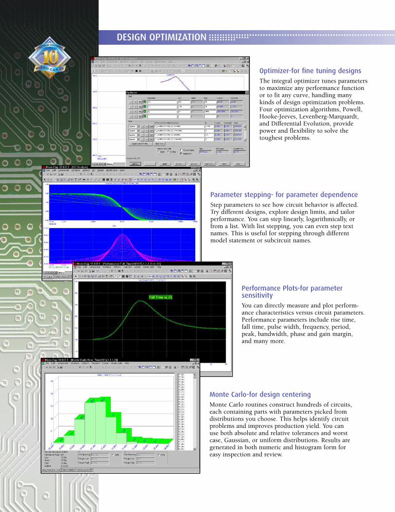
Optimizer-for fine tuning designsThe integral optimizer tunes parametersto maximize any performance functionor to fit any curve, handling many kinds of design optimization problems. Four optimization algorithms, Powell, Hooke-Jeeves, Levenberg-Marquardt, and Differential Evolution, providepower and flexibility to solve the toughest problems.
Parameter stepping- for parameter dependenceStep parameters to see how circuit behavior is affected.Try different designs, explore design limits, and tailorperformance. You can step linearly, logarithmically, orfrom a list. With list stepping, you can even step textnames. This is useful for stepping through differentmodel statement or subcircuit names.
Performance Plots-for parameter sensitivityYou can directly measure and plot perform-ance characteristics versus circuit parameters.Performance parameters include rise time, fall time, pulse width, frequency, period, peak, bandwidth, phase and gain margin, and many more.
Monte Carlo-for design centeringMonte Carlo routines construct hundreds of circuits,each containing parts with parameters picked fromdistributions you choose. This helps identify circuitproblems and improves production yield. You can use both absolute and relative tolerances and worstcase, Gaussian, or uniform distributions. Results aregenerated in both numeric and histogram form foreasy inspection and review.
� � � � � � � � � � � � � � � � � � � � � � � � � � � � � � � � � � � � � � � � � � � � � � � � � � � � � � � � � � � � � � � � � � � � � �� � � � � � � � � � � � � � �� � � � � � � � � �
� � � � � � � � � � � � � � � � � � � � � � � � � � � � � � � � � � � � � � � � � � � � � � � � � � �� � � � � � � � � � � � � � �� � � � � � � � � �MODELING
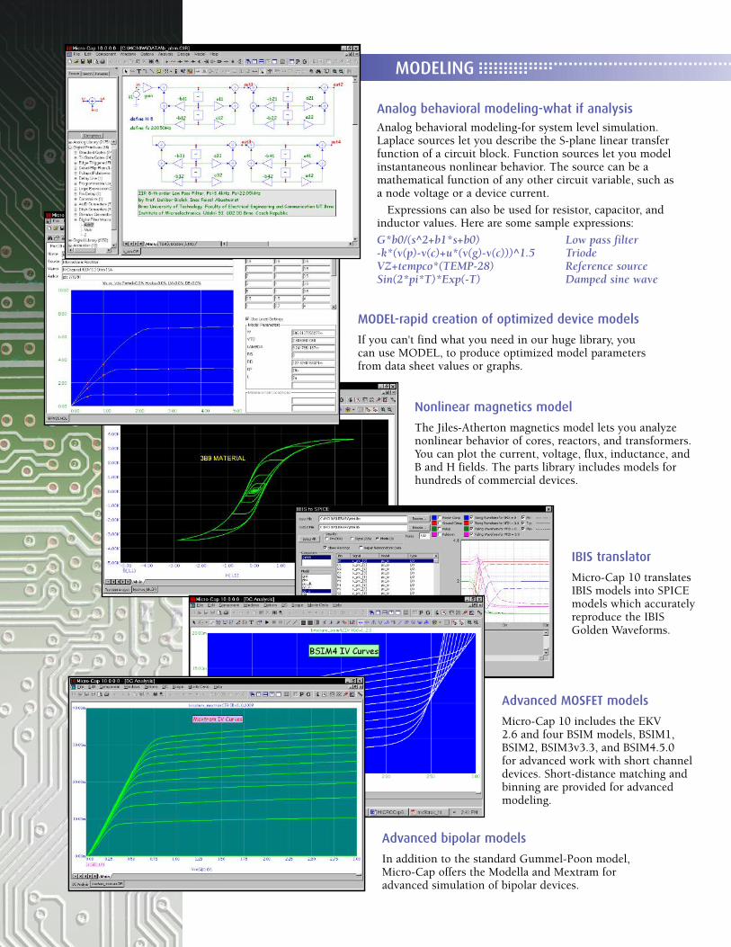
MODEL-rapid creation of optimized device models
If you can't find what you need in our huge library, youcan use MODEL, to produce optimized model parametersfrom data sheet values or graphs.
Nonlinear magnetics model
The Jiles-Atherton magnetics model lets you analyze nonlinear behavior of cores, reactors, and transformers.You can plot the current, voltage, flux, inductance, andB and H fields. The parts library includes models forhundreds of commercial devices.
IBIS translator
Micro-Cap 10 translatesIBIS models into SPICEmodels which accuratelyreproduce the IBISGolden Waveforms.
Advanced MOSFET models
Micro-Cap 10 includes the EKV 2.6 and four BSIM models, BSIM1,BSIM2, BSIM3v3.3, and BSIM4.5.0 for advanced work with short channeldevices. Short-distance matching andbinning are provided for advancedmodeling.
Advanced bipolar models
In addition to the standard Gummel-Poon model, Micro-Cap offers the Modella and Mextram for advanced simulation of bipolar devices.
Analog behavioral modeling-what if analysisAnalog behavioral modeling-for system level simulation.Laplace sources let you describe the S-plane linear transferfunction of a circuit block. Function sources let you modelinstantaneous nonlinear behavior. The source can be a mathematical function of any other circuit variable, such as a node voltage or a device current.
Expressions can also be used for resistor, capacitor, andinductor values. Here are some sample expressions:
G*b0/(s^2+b1*s+b0) Low pass filter-k*(v(p)-v(c)+u*(v(g)-v(c)))^1.5 TriodeVZ+tempco*(TEMP-28) Reference sourceSin(2*pi*T)*Exp(-T) Damped sine wave
� � � � � � � � � � � � � � � � � � � �
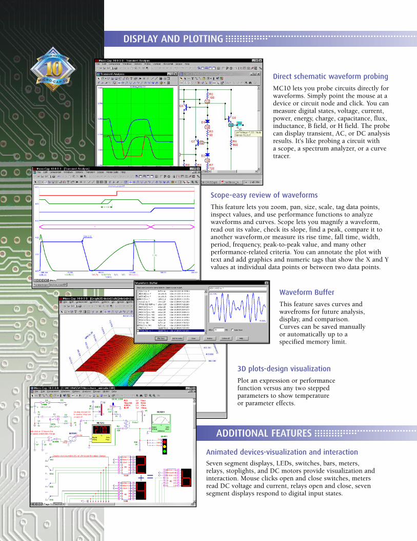
Scope-easy review of waveforms
This feature lets you zoom, pan, size, scale, tag data points,inspect values, and use performance functions to analyzewaveforms and curves. Scope lets you magnify a waveform,read out its value, check its slope, find a peak, compare it toanother waveform,or measure its rise time, fall time, width,period, frequency, peak-to-peak value, and many other performance-related criteria. You can annotate the plot withtext and add graphics and numeric tags that show the X and Yvalues at individual data points or between two data points.
Waveform Buffer
This feature saves curves and wavefroms for future analysis, display, and comparison. Curves can be saved manually or automatically up to a specified memory limit.
3D plots-design visualization
Plot an expression or performancefunction versus any two steppedparameters to show temperature or parameter effects.
Animated devices-visualization and interaction
Seven segment displays, LEDs, switches, bars, meters,relays, stoplights, and DC motors provide visualization andinteraction. Mouse clicks open and close switches, metersread DC voltage and current, relays open and close, sevensegment displays respond to digital input states.
Direct schematic waveform probing
MC10 lets you probe circuits directly forwaveforms. Simply point the mouse at adevice or circuit node and click. You canmeasure digital states, voltage, current,power, energy, charge, capacitance, flux,inductance, B field, or H field. The probecan display transient, AC, or DC analysisresults. It's like probing a circuit with a scope, a spectrum analyzer, or a curvetracer.
DISPLAY AND PLOTTING
ADDITIONAL FEATURES � � � � � � � � � � � � � � � � � � � � � � � � � � � � � � � � � � � � �� � � � � � � � � � � � � � �� � � � � � � � � �
� � � � � � � � � � � � � � � � � � � � � � � � � � � � � � � � � � � � � � � � � � � � � � � � � � � � � � � � � � � � � � � � � � � �� � � � � � � � � � � � � � �� � � � � � � � � �
Large device libraryWith over 24,000 parts in the devicemodel library, you'll be able to quicklyfind most digital parts, and analog partslike diodes, MOSFETs, BJTs, OPAMPs,IGBTs, JFETs, magnetic cores, crystals,and SCRs.
Waveform import capabilityThis feature lets you import waveformsfrom SPICE or Micro-Cap 10 outputfiles for direct comparison. You can alsouse the difa() and difd() functions toautomatically compare two analog ordigital waveforms. They report differ-ences between the waveforms, simplify-ing testing.
Extensive mathematical operatorsand variablesOperators include arithmetic, trigono-metric, hyperbolic, Boolean, relational,integration, differentiation, and FFT orsignal processing types. You can even doBessel functions and infinite seriesexpressions. Variables include voltage,current, power, energy, charge, flux,capacitance, resistance, inductance, Bfield, and H field. Device variablesinclude lead currents and lead-to-leadvoltages, such as base current and base-emitter voltage of an NPN.
Analog Primitives• Battery voltage source• Voltage source (SPICE format)• Current source (SPICE format)• Pulse voltage source• Sine voltage source• User-defined file source• Resistor• Capacitor• Inductor• Diode• SPICE E, F, G, H sources• Linear dependent two port source• Transmission line (lossy or ideal)• Transformer• K device (magnetic coupling)• Bipolar junction transistor (3 types)
Gummel-PoonMextramModella
• MOSFET models (13 types)Original levels 1, 2, and 3BSIM, BSIM2, BSIM3v3.3, BSIM4.5.0EKV V2.6Philips MOS 11, 20, 31, 40, and PSP 102
• Hefner IGBT model• OPAMP• GaAsFET (3 models)• JFET
• Analog behavioral sourcesLaplace function (S-domain expressions)Laplace table (S-domain tabular functions)Function (Time-domain algebraic expressions)
Table (Time-domain tabular functions)• Z transform source• Sample and hold source• S-Y-Z-H-G-T-ABCD parameter
N-port model• Switches (3 types)• Timer function block• Macro blocks
Absolute valueAmplifierCenter-tapped transformerClip functionComparatorCrystalDelayDIACDifferentiatorDigital potentiometerDividerF(s) Laplace blockFrequency shift keyerGyratorIdeal transformer 2 portIdeal transformer 3 portIntegratorMultiplierNoise sourcePhase shift keyerPotentiometerProgrammable unijunction transistorPulse width modulatorRelayResonant tank circuitSchmitt triggerSilicon-controlled rectifierSlip circuitSnubber diodeSpark gapSubtractorSummer (two input)Summer (three input)TriacTriodeVoltage-controlled oscillatorWideband transformer
Digital primitives• Standard and tri-state gatesBufferInverterAndOrNandNorXorNXor
• Edge-triggered flip-flopsJK typeD type
• Gated flip-flops and latchesSRLatch
• Digital loadsPullupPulldown
• Delay line• Programmable logic array• Analog to digital converter• Digital to analog converter• Analog to digital interface• Digital to analog interface• Digital behavioral modeling
Logic expressionPin delayConstraint checker
• Stimulus generators
Animated primitivesThese versatile devices use motion andcolor to indicate state behavior andrespond to mouse clicks.• Analog / digital voltmeter/ammeter• Analog color LED• Analog color bar• DC Motor• Digital LED• Digital switch• SPDT, SPST, DPST switches• Relay• Seven segment display• Traffic light
Extensive help system• Over 20,000 lines of on-line help is context sensitive, indexed, and topicallyarranged for easy learning.
• Over 500 error messages help you pinpoint circuit problems. Most errormessages come with a "More" button for additional description of the natureof the problem.
• Over 200 sample circuits give you plenty of examples to learn design and simulation techniques.
• Over 100 Help Bar notes describe program features as you move the mouse over them.• Over 20 live demos illustrate the workings of the program.
Spectrum Software1021 South Wolfe RoadSunnyvale, CA 94086Tel: 408-738-4387FAX: 408-738-4702Internet: www.spectrum-soft.comSupport: [email protected]: [email protected]