Micko Scale Reproductions - Welcome to Manzano Laser Works
19
Micko Scale Reproductions Fun Scale F8F-1 Bearcat Photo by Joe Babalon Thank you for purchasing the F8F-1 Bearcat model. This is a continuation in a “Fun Scale” series of aircraft designed for optimum flight performance while retaining sport scale appearance. The design layout is similar to a large free flight model; light weight construction and stringers are the main features. The model features retracts and is designed to use stock parts from other models. The retracts/struts and tail wheel assembly are off the FMS P-51 1700 model and the power system and propeller are off the FMS P-47 1700 model. There is some sheeting on this model, but the design allows the modeler to modify the build according to their likes- such as sheeting the entire model and/or adding flaps. If the modeler decides to add sheeting, it is recommended to use from 1/32” to 3/32” balsa or 2mm Depron. The prototype model features retracts and with an all up flight weight of 8 pounds. With that weight the wing loading is 23-24 ounces per square foot. The construction techniques require intermediate skills but the airplane’s flight characteristics make it a good first scale subject. If it has been a long time since you have built a model, or if this is your first build, you may wish to purchase and practice on a Guillows or like type free flight model, as the construction style is similar. The photos used in this manual were from the prototype build and some parts have been updated (such as the Vertical Tail design and Tail Wheel (TW) unit used). Please refer to the plans for any items that do not match the photos. Prep Work, Tools, and Specialty Items No special tools are needed but there are a few items the builder might find useful. A balsa stripper was used to cut all the stringers. A small razor saw or “Zona” makes for ease in cutting across stringers. Small
Transcript of Micko Scale Reproductions - Welcome to Manzano Laser Works
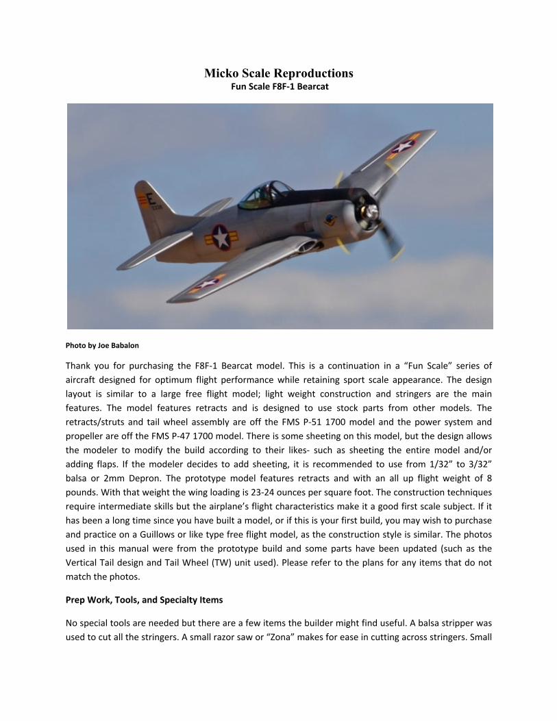
Micko Scale Reproductions Fun Scale F8F-1 Bearcat
Photo by Joe Babalon
Thank you for purchasing the F8F-1 Bearcat model. This is a continuation in a “Fun Scale” series of
aircraft designed for optimum flight performance while retaining sport scale appearance. The design
layout is similar to a large free flight model; light weight construction and stringers are the main
features. The model features retracts and is designed to use stock parts from other models. The
retracts/struts and tail wheel assembly are off the FMS P-51 1700 model and the power system and
propeller are off the FMS P-47 1700 model. There is some sheeting on this model, but the design allows
the modeler to modify the build according to their likes- such as sheeting the entire model and/or
adding flaps. If the modeler decides to add sheeting, it is recommended to use from 1/32” to 3/32”
balsa or 2mm Depron. The prototype model features retracts and with an all up flight weight of 8
pounds. With that weight the wing loading is 23-24 ounces per square foot. The construction techniques
require intermediate skills but the airplane’s flight characteristics make it a good first scale subject. If it
has been a long time since you have built a model, or if this is your first build, you may wish to purchase
and practice on a Guillows or like type free flight model, as the construction style is similar. The photos
used in this manual were from the prototype build and some parts have been updated (such as the
Vertical Tail design and Tail Wheel (TW) unit used). Please refer to the plans for any items that do not
match the photos.
Prep Work, Tools, and Specialty Items
No special tools are needed but there are a few items the builder might find useful. A balsa stripper was
used to cut all the stringers. A small razor saw or “Zona” makes for ease in cutting across stringers. Small
files and sanding blocks, especially nail files can be handy. One item that is very useful is a 90 degree
triangle. Several sizes and types are recommended. These can be purchased from a hobby shop or a
home improvement store. A small level also comes in handy throughout the build. The entire model was
covered Coverite Micro Lite with only a “Trim iron”. The glues used throughout the build were CA and
Titebond Wood Glue.
It’s best at this time to decide how you plan on completing the model. Do you wish to add sheeting,
flaps, full cockpit? Knowing these items in advance can help prepare the model from the start for these
options. As each modeler will tailor the model to their own desires, not every step in the construction
will be covered; just the main points.
Horizontal Stab and Elevator
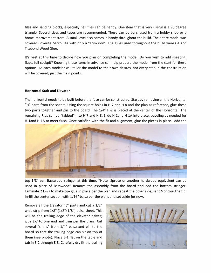
The horizontal needs to be built before the fuse can be constructed. Start by removing all the Horizontal
“H” parts from the sheets. Using the square holes in H-7 and H-8 and the plan as reference, glue these
two parts together and pin to the board. The 1/4” H-2 is placed at the center of the Horizontal. The
remaining Ribs can be “tabbed” into H-7 and H-8. Slide H-1and H-1A into place, beveling as needed for
H-1and H-1A to meet flush. Once satisfied with the fit and alignment, glue the pieces in place. Add the
top 1/8” sqr. Basswood stringer at this time. *Note- Spruce or another hardwood equivalent can be
used in place of Basswood* Remove the assembly from the board and add the bottom stringer.
Laminate 2 H-9s to make tip- glue in place per the plan and repeat the other side; sand/contour the tip.
In-fill the center section with 1/16” balsa per the plans and set aside for now.
Remove all the Elevator “E” parts and cut a 1/2”
wide strip from 1/8” (1/2”x1/8”) balsa sheet. This
will be the trailing edge of the elevator halves;
glue E-7 to one end and trim per the plans. Cut
several “shims” from 1/4” balsa and pin to the
board so that the trailing edge can sit on top of
them (see photo). Place E-1 flat on the table and
tab in E-2 through E-8. Carefully dry fit the trailing
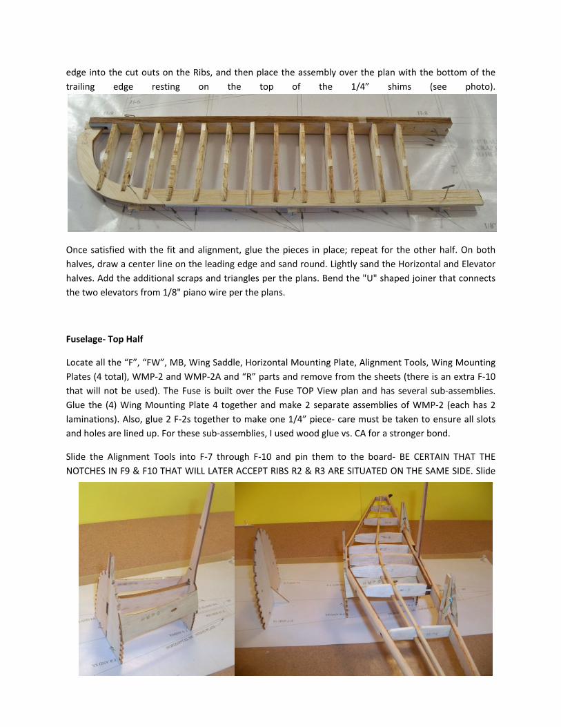
edge into the cut outs on the Ribs, and then place the assembly over the plan with the bottom of the
trailing edge resting on the top of the 1/4” shims (see photo).
Once satisfied with the fit and alignment, glue the pieces in place; repeat for the other half. On both
halves, draw a center line on the leading edge and sand round. Lightly sand the Horizontal and Elevator
halves. Add the additional scraps and triangles per the plans. Bend the "U" shaped joiner that connects
the two elevators from 1/8" piano wire per the plans.
Fuselage- Top Half
Locate all the “F”, “FW”, MB, Wing Saddle, Horizontal Mounting Plate, Alignment Tools, Wing Mounting
Plates (4 total), WMP-2 and WMP-2A and “R” parts and remove from the sheets (there is an extra F-10
that will not be used). The Fuse is built over the Fuse TOP View plan and has several sub-assemblies.
Glue the (4) Wing Mounting Plate 4 together and make 2 separate assemblies of WMP-2 (each has 2
laminations). Also, glue 2 F-2s together to make one 1/4” piece- care must be taken to ensure all slots
and holes are lined up. For these sub-assemblies, I used wood glue vs. CA for a stronger bond.
Slide the Alignment Tools into F-7 through F-10 and pin them to the board- BE CERTAIN THAT THE
NOTCHES IN F9 & F10 THAT WILL LATER ACCEPT RIBS R2 & R3 ARE SITUATED ON THE SAME SIDE. Slide
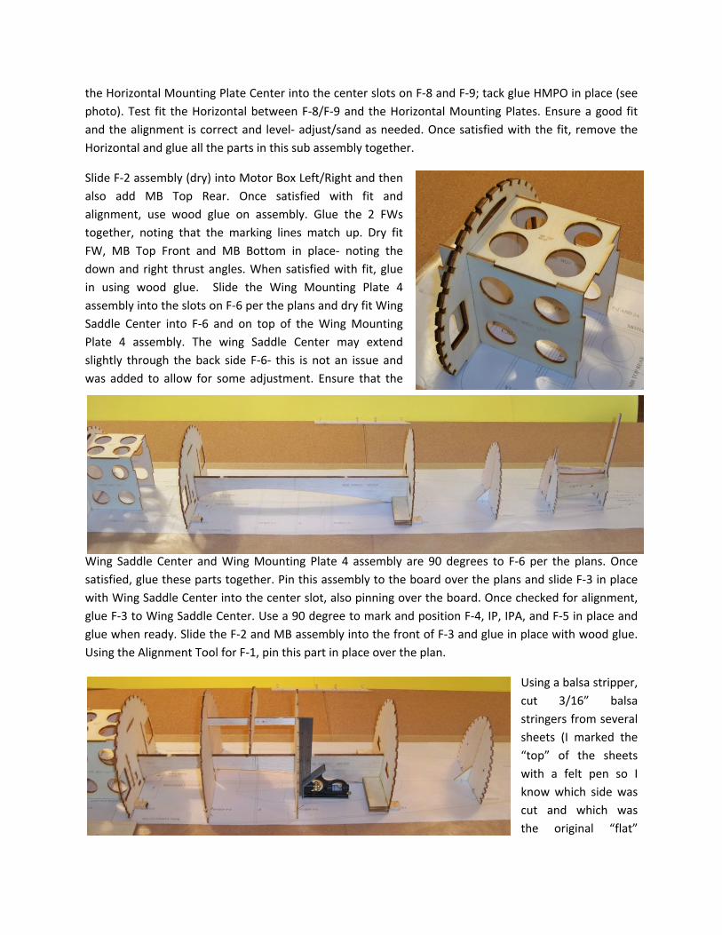
the Horizontal Mounting Plate Center into the center slots on F-8 and F-9; tack glue HMPO in place (see
photo). Test fit the Horizontal between F-8/F-9 and the Horizontal Mounting Plates. Ensure a good fit
and the alignment is correct and level- adjust/sand as needed. Once satisfied with the fit, remove the
Horizontal and glue all the parts in this sub assembly together.
Slide F-2 assembly (dry) into Motor Box Left/Right and then
also add MB Top Rear. Once satisfied with fit and
alignment, use wood glue on assembly. Glue the 2 FWs
together, noting that the marking lines match up. Dry fit
FW, MB Top Front and MB Bottom in place- noting the
down and right thrust angles. When satisfied with fit, glue
in using wood glue. Slide the Wing Mounting Plate 4
assembly into the slots on F-6 per the plans and dry fit Wing
Saddle Center into F-6 and on top of the Wing Mounting
Plate 4 assembly. The wing Saddle Center may extend
slightly through the back side F-6- this is not an issue and
was added to allow for some adjustment. Ensure that the
Wing Saddle Center and Wing Mounting Plate 4 assembly are 90 degrees to F-6 per the plans. Once
satisfied, glue these parts together. Pin this assembly to the board over the plans and slide F-3 in place
with Wing Saddle Center into the center slot, also pinning over the board. Once checked for alignment,
glue F-3 to Wing Saddle Center. Use a 90 degree to mark and position F-4, IP, IPA, and F-5 in place and
glue when ready. Slide the F-2 and MB assembly into the front of F-3 and glue in place with wood glue.
Using the Alignment Tool for F-1, pin this part in place over the plan.
Using a balsa stripper,
cut 3/16” balsa
stringers from several
sheets (I marked the
“top” of the sheets
with a felt pen so I
know which side was
cut and which was
the original “flat”
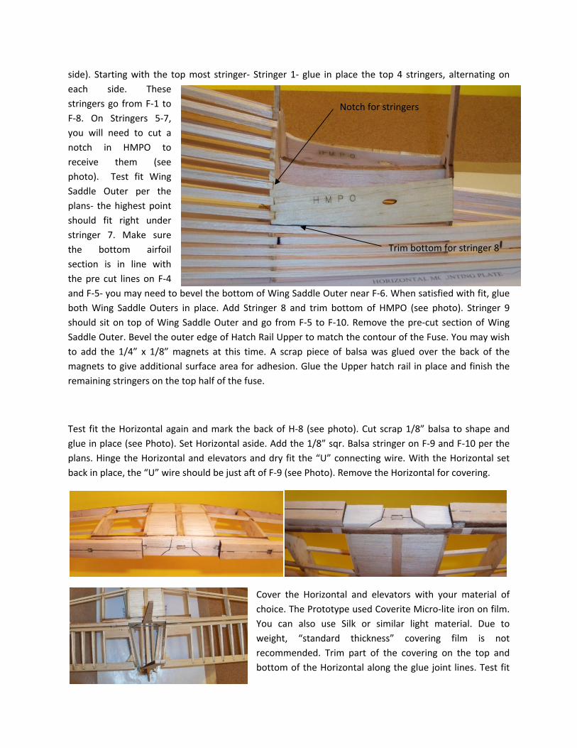
side). Starting with the top most stringer- Stringer 1- glue in place the top 4 stringers, alternating on
each side. These
stringers go from F-1 to
F-8. On Stringers 5-7,
you will need to cut a
notch in HMPO to
receive them (see
photo). Test fit Wing
Saddle Outer per the
plans- the highest point
should fit right under
stringer 7. Make sure
the bottom airfoil
section is in line with
the pre cut lines on F-4
and F-5- you may need to bevel the bottom of Wing Saddle Outer near F-6. When satisfied with fit, glue
both Wing Saddle Outers in place. Add Stringer 8 and trim bottom of HMPO (see photo). Stringer 9
should sit on top of Wing Saddle Outer and go from F-5 to F-10. Remove the pre-cut section of Wing
Saddle Outer. Bevel the outer edge of Hatch Rail Upper to match the contour of the Fuse. You may wish
to add the 1/4” x 1/8” magnets at this time. A scrap piece of balsa was glued over the back of the
magnets to give additional surface area for adhesion. Glue the Upper hatch rail in place and finish the
remaining stringers on the top half of the fuse.
Test fit the Horizontal again and mark the back of H-8 (see photo). Cut scrap 1/8” balsa to shape and
glue in place (see Photo). Set Horizontal aside. Add the 1/8” sqr. Balsa stringer on F-9 and F-10 per the
plans. Hinge the Horizontal and elevators and dry fit the “U” connecting wire. With the Horizontal set
back in place, the “U” wire should be just aft of F-9 (see Photo). Remove the Horizontal for covering.
Cover the Horizontal and elevators with your material of
choice. The Prototype used Coverite Micro-lite iron on film.
You can also use Silk or similar light material. Due to
weight, “standard thickness” covering film is not
recommended. Trim part of the covering on the top and
bottom of the Horizontal along the glue joint lines. Test fit
Trim bottom for stringer 8
Notch for stringers
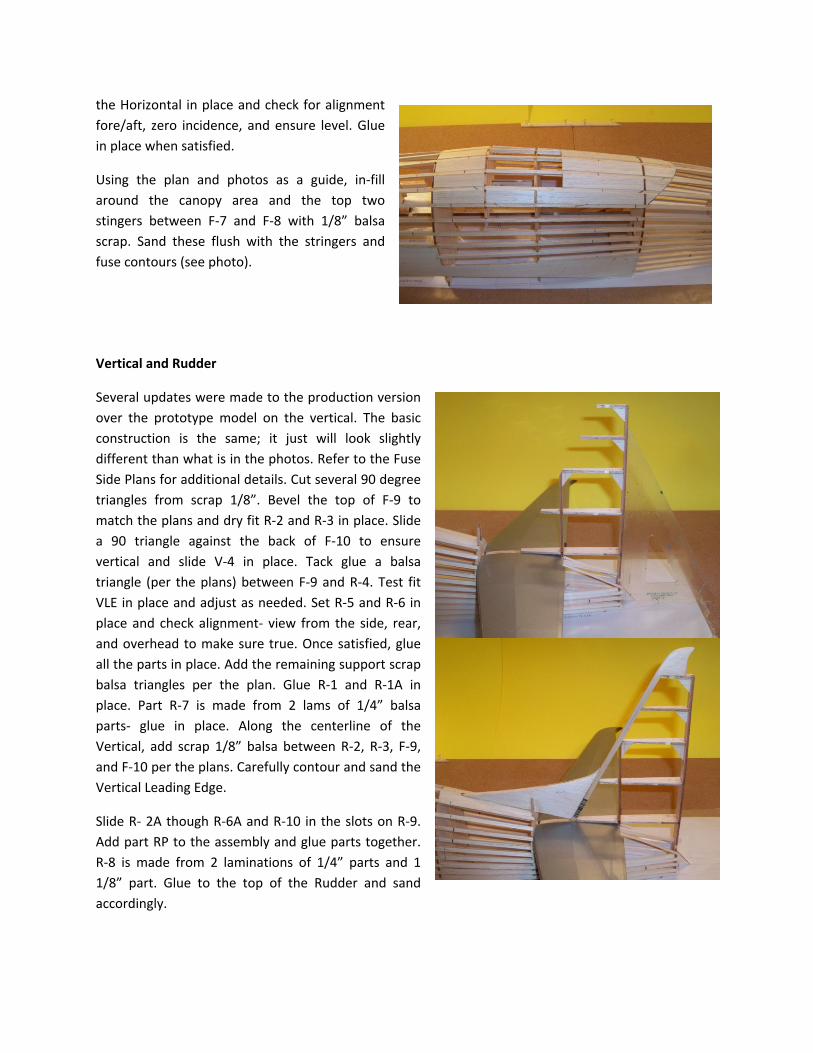
the Horizontal in place and check for alignment
fore/aft, zero incidence, and ensure level. Glue
in place when satisfied.
Using the plan and photos as a guide, in-fill
around the canopy area and the top two
stingers between F-7 and F-8 with 1/8” balsa
scrap. Sand these flush with the stringers and
fuse contours (see photo).
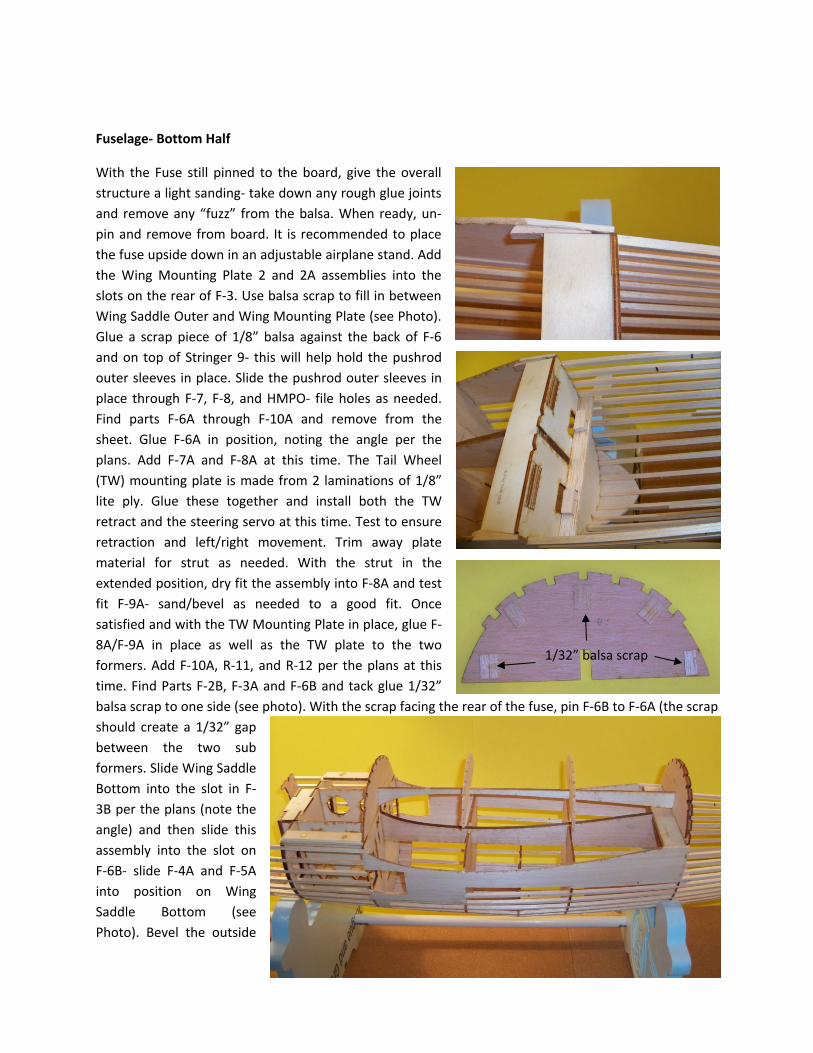
Vertical and Rudder
Several updates were made to the production version
over the prototype model on the vertical. The basic
construction is the same; it just will look slightly
different than what is in the photos. Refer to the Fuse
Side Plans for additional details. Cut several 90 degree
triangles from scrap 1/8”. Bevel the top of F-9 to
match the plans and dry fit R-2 and R-3 in place. Slide
a 90 triangle against the back of F-10 to ensure
vertical and slide V-4 in place. Tack glue a balsa
triangle (per the plans) between F-9 and R-4. Test fit
VLE in place and adjust as needed. Set R-5 and R-6 in
place and check alignment- view from the side, rear,
and overhead to make sure true. Once satisfied, glue
all the parts in place. Add the remaining support scrap
balsa triangles per the plan. Glue R-1 and R-1A in
place. Part R-7 is made from 2 lams of 1/4” balsa
parts- glue in place. Along the centerline of the
Vertical, add scrap 1/8” balsa between R-2, R-3, F-9,
and F-10 per the plans. Carefully contour and sand the
Vertical Leading Edge.
Slide R- 2A though R-6A and R-10 in the slots on R-9.
Add part RP to the assembly and glue parts together.
R-8 is made from 2 laminations of 1/4” parts and 1
1/8” part. Glue to the top of the Rudder and sand
accordingly.
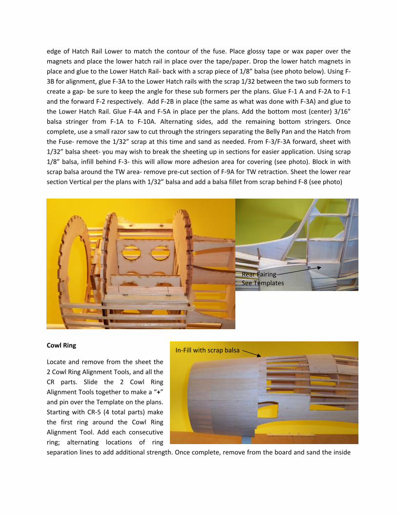
Fuselage- Bottom Half
With the Fuse still pinned to the board, give the overall
structure a light sanding- take down any rough glue joints
and remove any “fuzz” from the balsa. When ready, un-
pin and remove from board. It is recommended to place
the fuse upside down in an adjustable airplane stand. Add
the Wing Mounting Plate 2 and 2A assemblies into the
slots on the rear of F-3. Use balsa scrap to fill in between
Wing Saddle Outer and Wing Mounting Plate (see Photo).
Glue a scrap piece of 1/8” balsa against the back of F-6
and on top of Stringer 9- this will help hold the pushrod
outer sleeves in place. Slide the pushrod outer sleeves in
place through F-7, F-8, and HMPO- file holes as needed.
Find parts F-6A through F-10A and remove from the
sheet. Glue F-6A in position, noting the angle per the
plans. Add F-7A and F-8A at this time. The Tail Wheel
(TW) mounting plate is made from 2 laminations of 1/8”
lite ply. Glue these together and install both the TW
retract and the steering servo at this time. Test to ensure
retraction and left/right movement. Trim away plate
material for strut as needed. With the strut in the
extended position, dry fit the assembly into F-8A and test
fit F-9A- sand/bevel as needed to a good fit. Once
satisfied and with the TW Mounting Plate in place, glue F-
8A/F-9A in place as well as the TW plate to the two
formers. Add F-10A, R-11, and R-12 per the plans at this
time. Find Parts F-2B, F-3A and F-6B and tack glue 1/32”
balsa scrap to one side (see photo). With the scrap facing the rear of the fuse, pin F-6B to F-6A (the scrap
should create a 1/32” gap
between the two sub
formers. Slide Wing Saddle
Bottom into the slot in F-
3B per the plans (note the
angle) and then slide this
assembly into the slot on
F-6B- slide F-4A and F-5A
into position on Wing
Saddle Bottom (see
Photo). Bevel the outside
1/32” balsa scrap
edge of Hatch Rail Lower to match the contour of the fuse. Place glossy tape or wax paper over the
magnets and place the lower hatch rail in place over the tape/paper. Drop the lower hatch magnets in
place and glue to the Lower Hatch Rail- back with a scrap piece of 1/8” balsa (see photo below). Using F-
3B for alignment, glue F-3A to the Lower Hatch rails with the scrap 1/32 between the two sub formers to
create a gap- be sure to keep the angle for these sub formers per the plans. Glue F-1 A and F-2A to F-1
and the forward F-2 respectively. Add F-2B in place (the same as what was done with F-3A) and glue to
the Lower Hatch Rail. Glue F-4A and F-5A in place per the plans. Add the bottom most (center) 3/16”
balsa stringer from F-1A to F-10A. Alternating sides, add the remaining bottom stringers. Once
complete, use a small razor saw to cut through the stringers separating the Belly Pan and the Hatch from
the Fuse- remove the 1/32” scrap at this time and sand as needed. From F-3/F-3A forward, sheet with
1/32” balsa sheet- you may wish to break the sheeting up in sections for easier application. Using scrap
1/8” balsa, infill behind F-3- this will allow more adhesion area for covering (see photo). Block in with
scrap balsa around the TW area- remove pre-cut section of F-9A for TW retraction. Sheet the lower rear
section Vertical per the plans with 1/32” balsa and add a balsa fillet from scrap behind F-8 (see photo)
Cowl Ring
Locate and remove from the sheet the
2 Cowl Ring Alignment Tools, and all the
CR parts. Slide the 2 Cowl Ring
Alignment Tools together to make a “+”
and pin over the Template on the plans.
Starting with CR-5 (4 total parts) make
the first ring around the Cowl Ring
Alignment Tool. Add each consecutive
ring; alternating locations of ring
separation lines to add additional strength. Once complete, remove from the board and sand the inside
In-Fill with scrap balsa
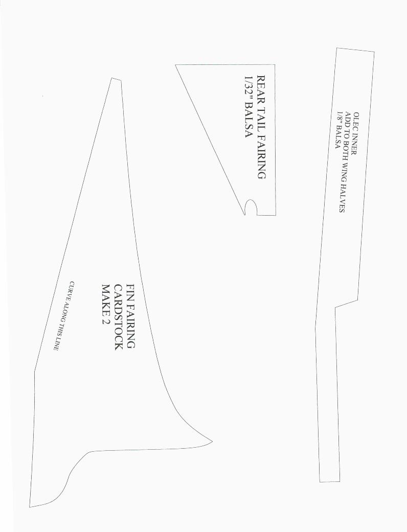
Rear Fairing-
See Templates
smooth; you may want to sand the inside lip/curve at this time. Test fit to the front of F-1 and glue in
place. Contour outside edge/curve to match the plans.
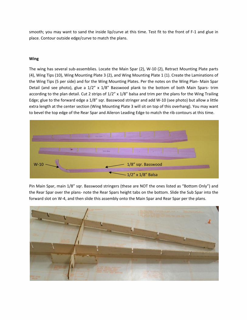
Wing
The wing has several sub-assemblies. Locate the Main Spar (2), W-10 (2), Retract Mounting Plate parts
(4), Wing Tips (10), Wing Mounting Plate 3 (2), and Wing Mounting Plate 1 (1). Create the Laminations of
the Wing Tips (5 per side) and for the Wing Mounting Plates. Per the notes on the Wing Plan- Main Spar
Detail (and see photo), glue a 1/2” x 1/8” Basswood plank to the bottom of both Main Spars- trim
according to the plan detail. Cut 2 strips of 1/2” x 1/8” balsa and trim per the plans for the Wing Trailing
Edge; glue to the forward edge a 1/8” sqr. Basswood stringer and add W-10 (see photo) but allow a little
extra length at the center section (Wing Mounting Plate 3 will sit on top of this overhang). You may want
to bevel the top edge of the Rear Spar and Aileron Leading Edge to match the rib contours at this time.
Pin Main Spar, main 1/8” sqr. Basswood stringers (these are NOT the ones listed as “Bottom Only”) and
the Rear Spar over the plans- note the Rear Spars height tabs on the bottom. Slide the Sub Spar into the
forward slot on W-4, and then slide this assembly onto the Main Spar and Rear Spar per the plans.
1/8” sqr. Basswood
1/2” x 1/8” Balsa
W-10
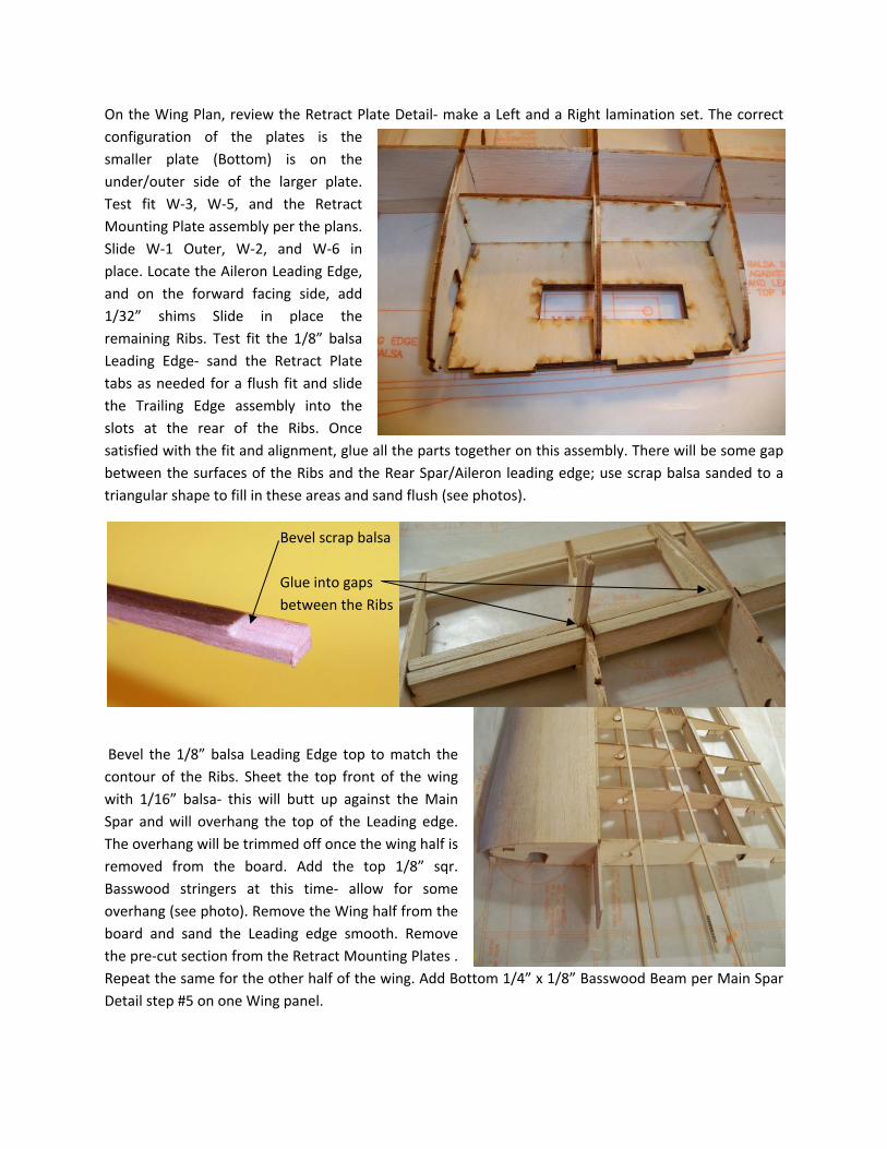
On the Wing Plan, review the Retract Plate Detail- make a Left and a Right lamination set. The correct
configuration of the plates is the
smaller plate (Bottom) is on the
under/outer side of the larger plate.
Test fit W-3, W-5, and the Retract
Mounting Plate assembly per the plans.
Slide W-1 Outer, W-2, and W-6 in
place. Locate the Aileron Leading Edge,
and on the forward facing side, add
1/32” shims Slide in place the
remaining Ribs. Test fit the 1/8” balsa
Leading Edge- sand the Retract Plate
tabs as needed for a flush fit and slide
the Trailing Edge assembly into the
slots at the rear of the Ribs. Once
satisfied with the fit and alignment, glue all the parts together on this assembly. There will be some gap
between the surfaces of the Ribs and the Rear Spar/Aileron leading edge; use scrap balsa sanded to a
triangular shape to fill in these areas and sand flush (see photos).
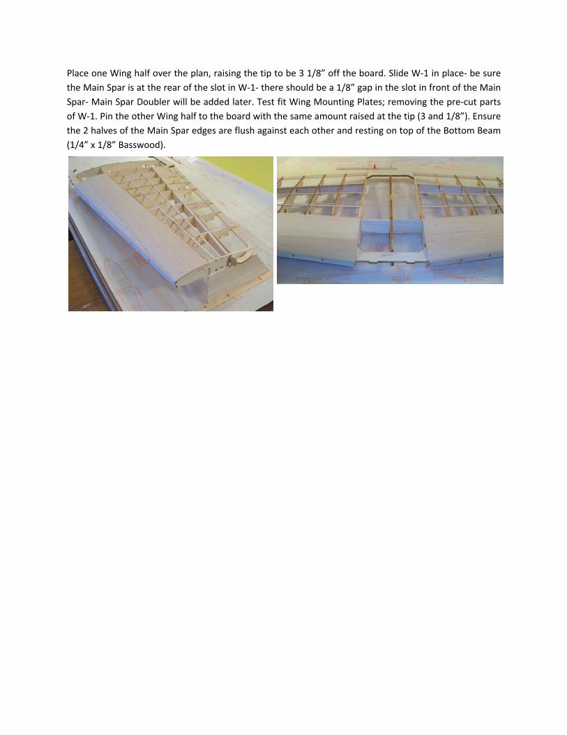
Bevel the 1/8” balsa Leading Edge top to match the
contour of the Ribs. Sheet the top front of the wing
with 1/16” balsa- this will butt up against the Main
Spar and will overhang the top of the Leading edge.
The overhang will be trimmed off once the wing half is
removed from the board. Add the top 1/8” sqr.
Basswood stringers at this time- allow for some
overhang (see photo). Remove the Wing half from the
board and sand the Leading edge smooth. Remove
the pre-cut section from the Retract Mounting Plates .
Repeat the same for the other half of the wing. Add Bottom 1/4” x 1/8” Basswood Beam per Main Spar
Detail step #5 on one Wing panel.
Bevel scrap balsa
Glue into gaps
between the Ribs
Place one Wing half over the plan, raising the tip to be 3 1/8” off the board. Slide W-1 in place- be sure
the Main Spar is at the rear of the slot in W-1- there should be a 1/8” gap in the slot in front of the Main
Spar- Main Spar Doubler will be added later. Test fit Wing Mounting Plates; removing the pre-cut parts
of W-1. Pin the other Wing half to the board with the same amount raised at the tip (3 and 1/8”). Ensure
the 2 halves of the Main Spar edges are flush against each other and resting on top of the Bottom Beam
(1/4” x 1/8” Basswood).
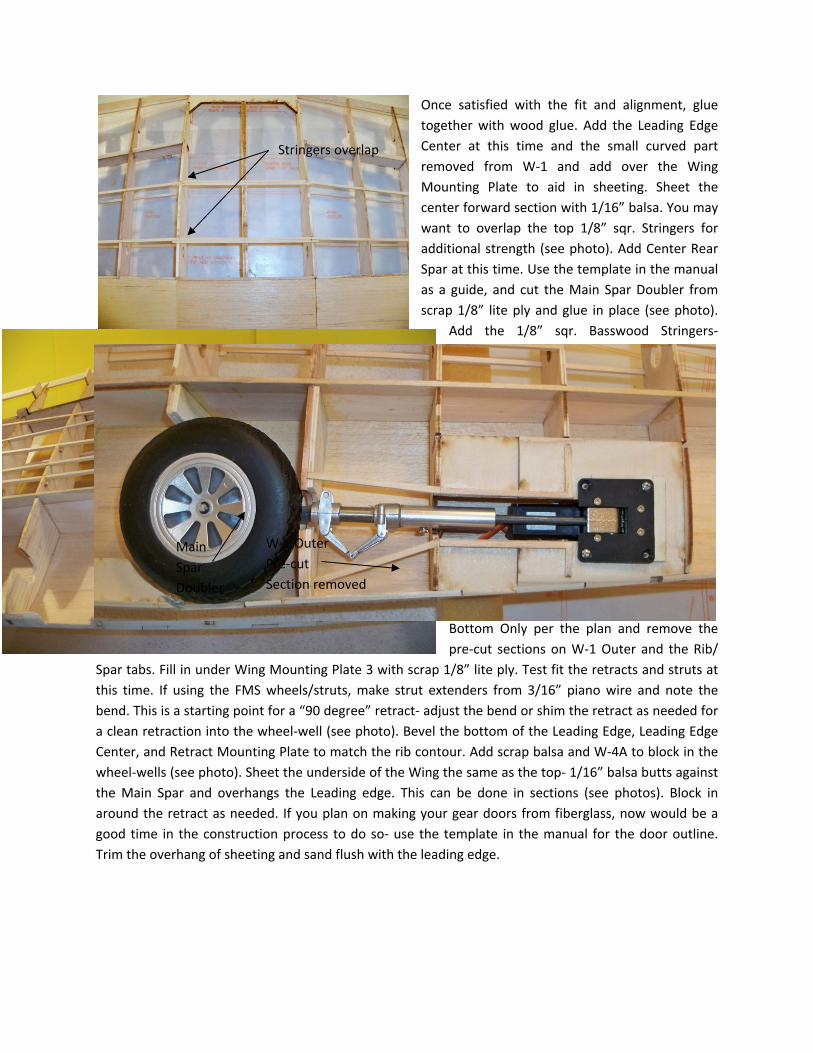
Once satisfied with the fit and alignment, glue
together with wood glue. Add the Leading Edge
Center at this time and the small curved part
removed from W-1 and add over the Wing
Mounting Plate to aid in sheeting. Sheet the
center forward section with 1/16” balsa. You may
want to overlap the top 1/8” sqr. Stringers for
additional strength (see photo). Add Center Rear
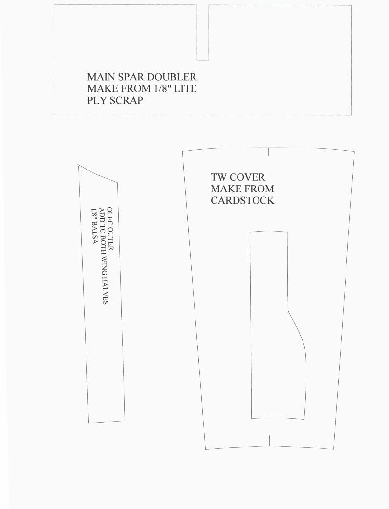
Spar at this time. Use the template in the manual
as a guide, and cut the Main Spar Doubler from
scrap 1/8” lite ply and glue in place (see photo).
Add the 1/8” sqr. Basswood Stringers-
Bottom Only per the plan and remove the
pre-cut sections on W-1 Outer and the Rib/
Spar tabs. Fill in under Wing Mounting Plate 3 with scrap 1/8” lite ply. Test fit the retracts and struts at
this time. If using the FMS wheels/struts, make strut extenders from 3/16” piano wire and note the
bend. This is a starting point for a “90 degree” retract- adjust the bend or shim the retract as needed for
a clean retraction into the wheel-well (see photo). Bevel the bottom of the Leading Edge, Leading Edge
Center, and Retract Mounting Plate to match the rib contour. Add scrap balsa and W-4A to block in the
wheel-wells (see photo). Sheet the underside of the Wing the same as the top- 1/16” balsa butts against
the Main Spar and overhangs the Leading edge. This can be done in sections (see photos). Block in
around the retract as needed. If you plan on making your gear doors from fiberglass, now would be a
good time in the construction process to do so- use the template in the manual for the door outline.
Trim the overhang of sheeting and sand flush with the leading edge.
Stringers overlap
Main
Spar
Doubler
W-1 Outer
Pre-cut
Section removed
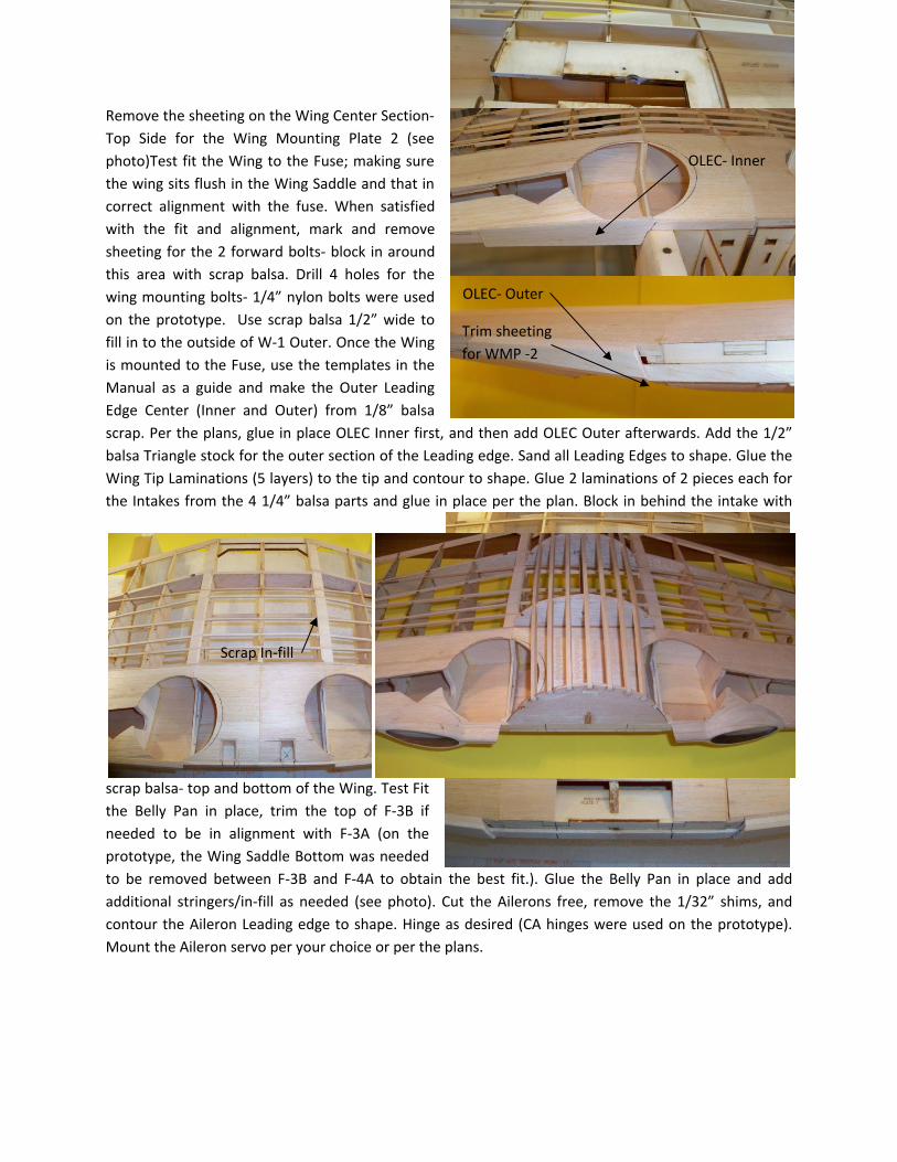
Remove the sheeting on the Wing Center Section-
Top Side for the Wing Mounting Plate 2 (see
photo)Test fit the Wing to the Fuse; making sure
the wing sits flush in the Wing Saddle and that in
correct alignment with the fuse. When satisfied
with the fit and alignment, mark and remove
sheeting for the 2 forward bolts- block in around
this area with scrap balsa. Drill 4 holes for the
wing mounting bolts- 1/4” nylon bolts were used
on the prototype. Use scrap balsa 1/2” wide to
fill in to the outside of W-1 Outer. Once the Wing
is mounted to the Fuse, use the templates in the
Manual as a guide and make the Outer Leading
Edge Center (Inner and Outer) from 1/8” balsa
scrap. Per the plans, glue in place OLEC Inner first, and then add OLEC Outer afterwards. Add the 1/2”
balsa Triangle stock for the outer section of the Leading edge. Sand all Leading Edges to shape. Glue the
Wing Tip Laminations (5 layers) to the tip and contour to shape. Glue 2 laminations of 2 pieces each for
the Intakes from the 4 1/4” balsa parts and glue in place per the plan. Block in behind the intake with
scrap balsa- top and bottom of the Wing. Test Fit
the Belly Pan in place, trim the top of F-3B if
needed to be in alignment with F-3A (on the
prototype, the Wing Saddle Bottom was needed
to be removed between F-3B and F-4A to obtain the best fit.). Glue the Belly Pan in place and add
additional stringers/in-fill as needed (see photo). Cut the Ailerons free, remove the 1/32” shims, and
contour the Aileron Leading edge to shape. Hinge as desired (CA hinges were used on the prototype).
Mount the Aileron servo per your choice or per the plans.
Trim sheeting
for WMP -2
OLEC- Inner
OLEC- Outer
Scrap In-fill
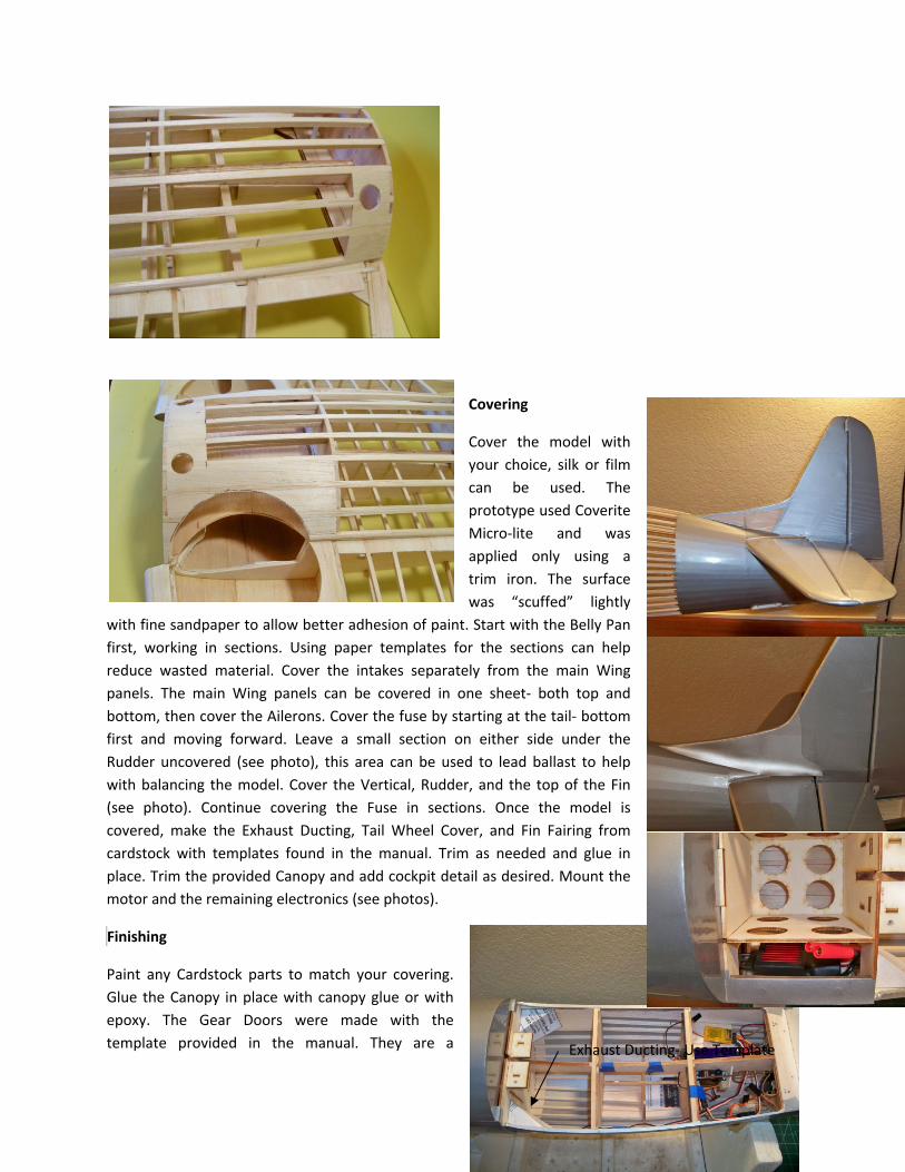
Covering
Cover the model with
your choice, silk or film
can be used. The
prototype used Coverite
Micro-lite and was
applied only using a
trim iron. The surface
was “scuffed” lightly
with fine sandpaper to allow better adhesion of paint. Start with the Belly Pan
first, working in sections. Using paper templates for the sections can help
reduce wasted material. Cover the intakes separately from the main Wing
panels. The main Wing panels can be covered in one sheet- both top and
bottom, then cover the Ailerons. Cover the fuse by starting at the tail- bottom
first and moving forward. Leave a small section on either side under the
Rudder uncovered (see photo), this area can be used to lead ballast to help
with balancing the model. Cover the Vertical, Rudder, and the top of the Fin
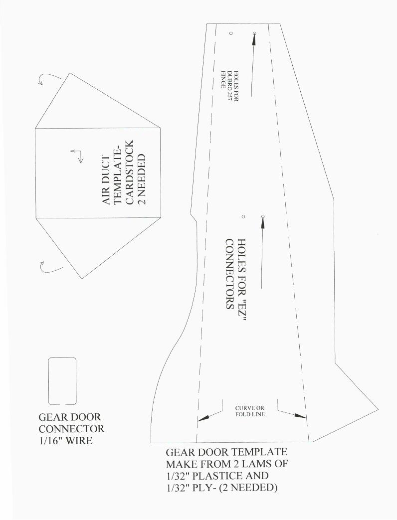
(see photo). Continue covering the Fuse in sections. Once the model is
covered, make the Exhaust Ducting, Tail Wheel Cover, and Fin Fairing from
cardstock with templates found in the manual. Trim as needed and glue in
place. Trim the provided Canopy and add cockpit detail as desired. Mount the
motor and the remaining electronics (see photos).
Finishing
Paint any Cardstock parts to match your covering.
Glue the Canopy in place with canopy glue or with
epoxy. The Gear Doors were made with the
template provided in the manual. They are a Exhaust Ducting- Use Template
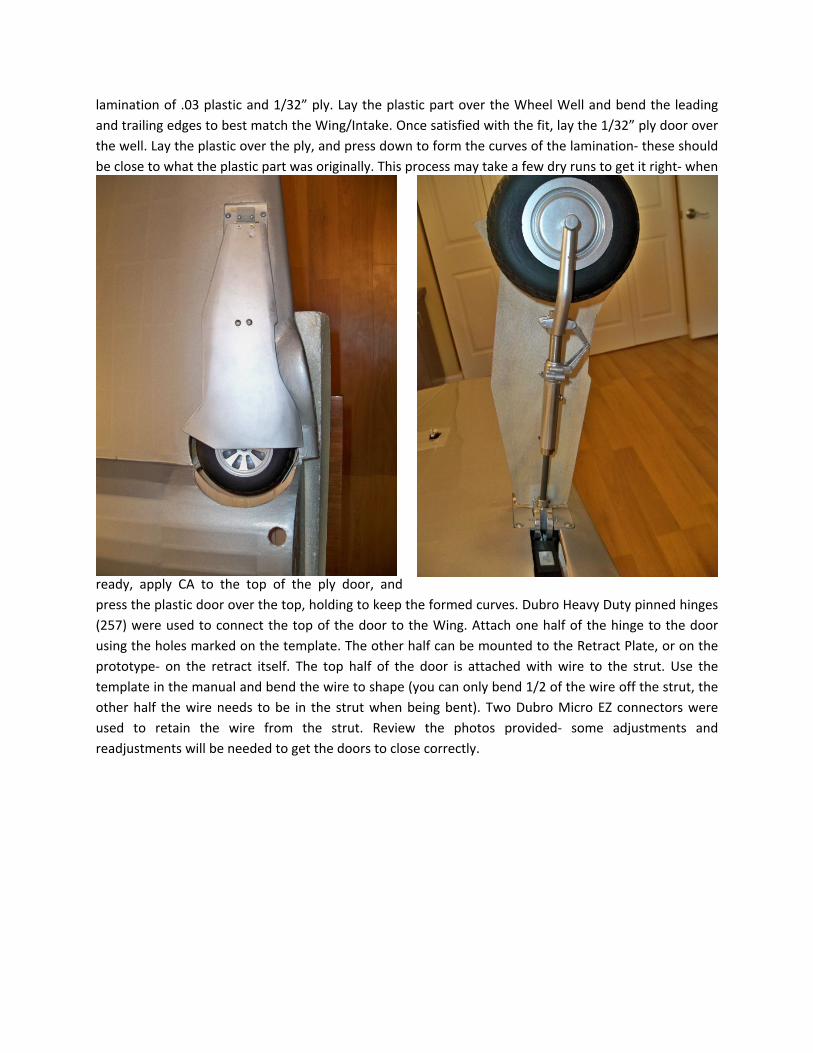
lamination of .03 plastic and 1/32” ply. Lay the plastic part over the Wheel Well and bend the leading
and trailing edges to best match the Wing/Intake. Once satisfied with the fit, lay the 1/32” ply door over
the well. Lay the plastic over the ply, and press down to form the curves of the lamination- these should
be close to what the plastic part was originally. This process may take a few dry runs to get it right- when
ready, apply CA to the top of the ply door, and
press the plastic door over the top, holding to keep the formed curves. Dubro Heavy Duty pinned hinges
(257) were used to connect the top of the door to the Wing. Attach one half of the hinge to the door
using the holes marked on the template. The other half can be mounted to the Retract Plate, or on the
prototype- on the retract itself. The top half of the door is attached with wire to the strut. Use the
template in the manual and bend the wire to shape (you can only bend 1/2 of the wire off the strut, the
other half the wire needs to be in the strut when being bent). Two Dubro Micro EZ connectors were
used to retain the wire from the strut. Review the photos provided- some adjustments and
readjustments will be needed to get the doors to close correctly.
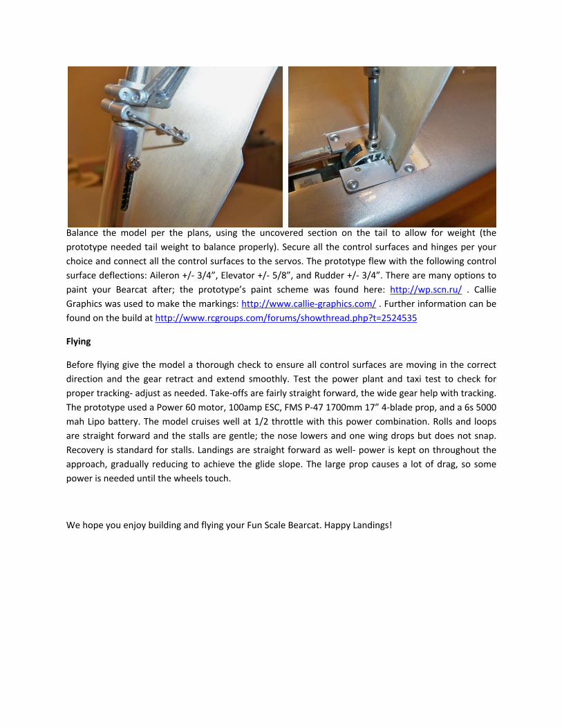
Balance the model per the plans, using the uncovered section on the tail to allow for weight (the
prototype needed tail weight to balance properly). Secure all the control surfaces and hinges per your
choice and connect all the control surfaces to the servos. The prototype flew with the following control
surface deflections: Aileron +/- 3/4”, Elevator +/- 5/8”, and Rudder +/- 3/4”. There are many options to
paint your Bearcat after; the prototype’s paint scheme was found here: http://wp.scn.ru/ . Callie
Graphics was used to make the markings: http://www.callie-graphics.com/ . Further information can be
found on the build at http://www.rcgroups.com/forums/showthread.php?t=2524535
Flying
Before flying give the model a thorough check to ensure all control surfaces are moving in the correct
direction and the gear retract and extend smoothly. Test the power plant and taxi test to check for
proper tracking- adjust as needed. Take-offs are fairly straight forward, the wide gear help with tracking.
The prototype used a Power 60 motor, 100amp ESC, FMS P-47 1700mm 17” 4-blade prop, and a 6s 5000
mah Lipo battery. The model cruises well at 1/2 throttle with this power combination. Rolls and loops
are straight forward and the stalls are gentle; the nose lowers and one wing drops but does not snap.
Recovery is standard for stalls. Landings are straight forward as well- power is kept on throughout the
approach, gradually reducing to achieve the glide slope. The large prop causes a lot of drag, so some
power is needed until the wheels touch.
We hope you enjoy building and flying your Fun Scale Bearcat. Happy Landings!