
Elwyn B. Robinson Department of Special Collections 7-1939 ...
Upload
julius-robinsonCategory
view
221download
0
MICE Absorber cryostat Forces and power
dissipation -for normal operation and during a
magnet quench
Elwyn Baynham
James RochfordMICE Meeting November 2003

Outline
Magnet Forces and Quench Issues»Scope
–To review the interactions between the magnet system and the H2 absorber units–Magnet system brief overview – focus coils and absorber geometry – separation of modules – not all latest geometry –Magnetic Forces
Static - schematic of forces on coils – internal/external – force management – interaction with absorber Quench – worst case unbalanced forces – management – interaction with absorber
–Quench – present eddy currents,forces,power generated in absorber bodies and windows – for both flip and solenoid mode
–Review Impact on absorber design and safety
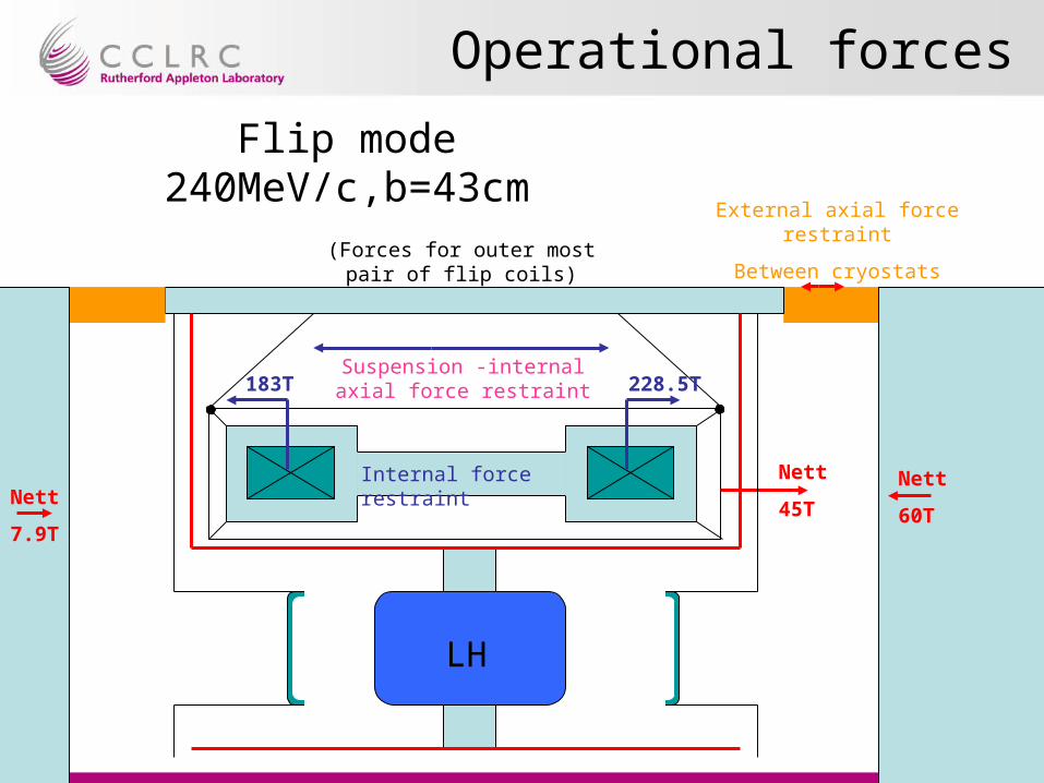
Operational forces
183T 228.5T
Internal force restraint
Suspension -internal axial force restraint
External axial force restraint
Between cryostats
Nett
45T
LH
Flip mode 240MeV/c,b=43cm
Nett
60TNett
7.9T
(Forces for outer most pair of flip coils)
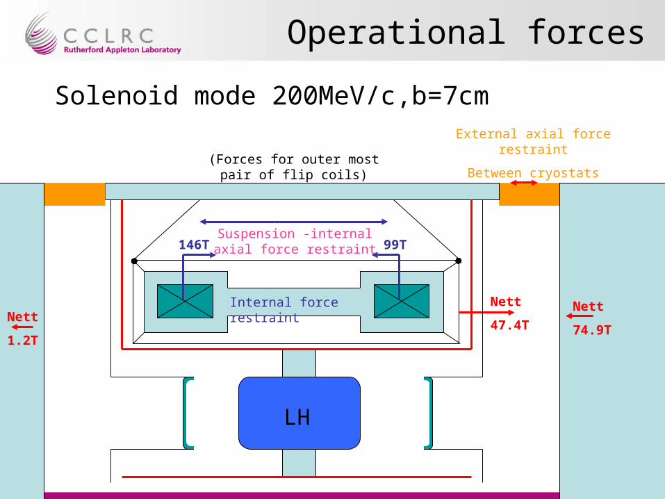
Operational forces
146T 99T
Internal force restraint
Suspension -internal axial force restraint
External axial force restraint
Between cryostats
Nett
47.4T
LH
Solenoid mode 200MeV/c,b=7cm
Nett
74.9TNett
1.2T
(Forces for outer most pair of flip coils)
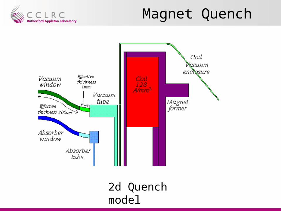
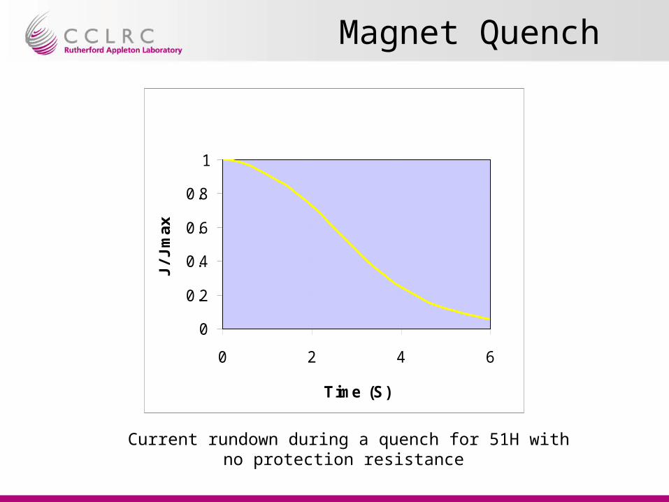
Magnet Quench
2d Quench model
Magnet Quench
Current rundown during a quench for 51H with no protection resistance
0
0.2
0.4
0.6
0.8
1
0 2 4 6
Time (S)
J/J
max

Magnet Quench
Eddy current distribution in holders and windows
2s into a quench whilst operating in 240MeV/C,Beta=43cm mode
Eddy current distribution in windows
in flip mode

Magnet Quench
Power dissipated in the inner vessel windows during a quench in 240MeV/C,Beta=43cmm mode
Windows power dissipation
0
5
10
15
20
25
0.00 1.00 2.00 3.00 4.00
Time (S)
pow
er (
W)
Vacuum window
Absorber window

Magnet Quench
Power dissipated in the inner vessel bodies during a quench in 240MeV/C,Beta=43cmm mode
Window holder power dissipation
0
1000
2000
3000
4000
5000
6000
7000
8000
9000
10000
0.00 1.00 2.00 3.00 4.00
Time (S)
pow
er (
W)
Vacuum body
Absorber body

Magnet Quench
Force on the inner vessel windows during a quench in 240MeV/C,Beta=43cm mode
Body f orce on windows
0
50
100
150
200
250
0.00 1.00 2.00 3.00 4.00
Time (S)
Axia
l For
ce (
N)
Vacuum window
Absorber window

Magnet Quench
rJB ..Using expression
We can estimate the peak stress in the window

Magnet Quench
Model changed to look at the effect of offsetting a window axially

Magnet Quench
Force on the inner vessel bodies during a quench in 240MeV/C,Beta=43cm mode with the vessels offset
axially by 5mm
Force on inner vesels off set by 5mm
-600
-400
-200
0
200
400
600
800
0.00 1.00 2.00 3.00 4.00
Time (S)
Axia
l For
ce (
N)
Vacuum body
Absorber body
Magnet Quench
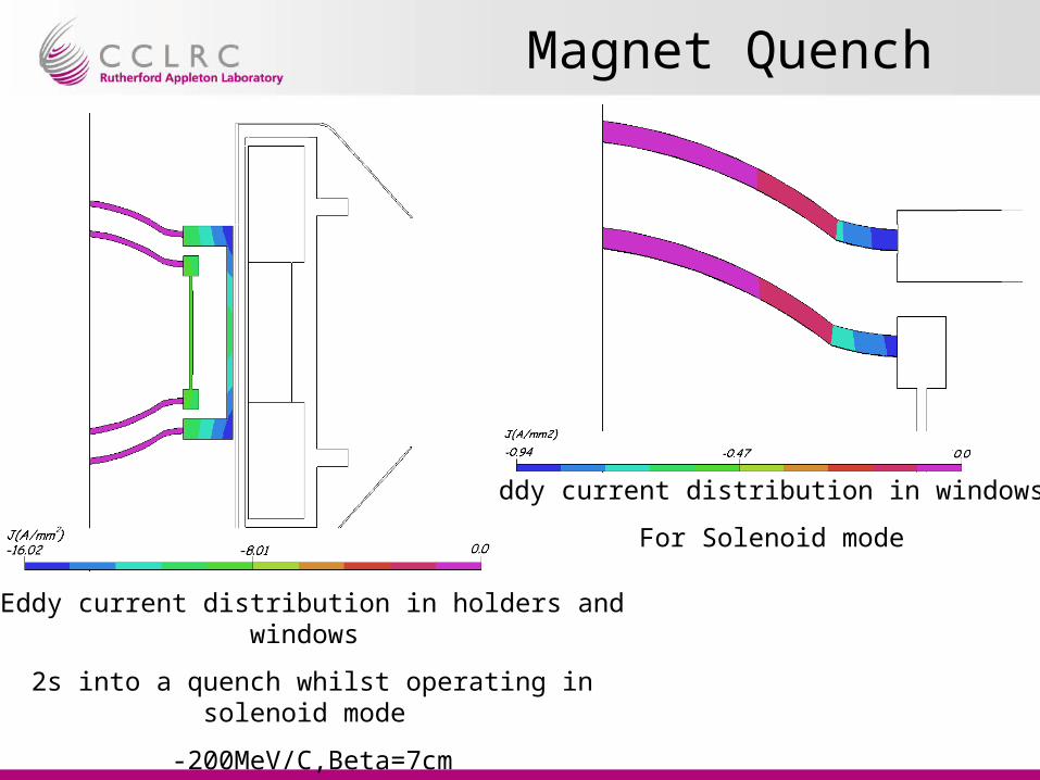
Eddy current distribution in holders and windows
2s into a quench whilst operating in solenoid mode
-200MeV/C,Beta=7cm
Eddy current distribution in windows
For Solenoid mode
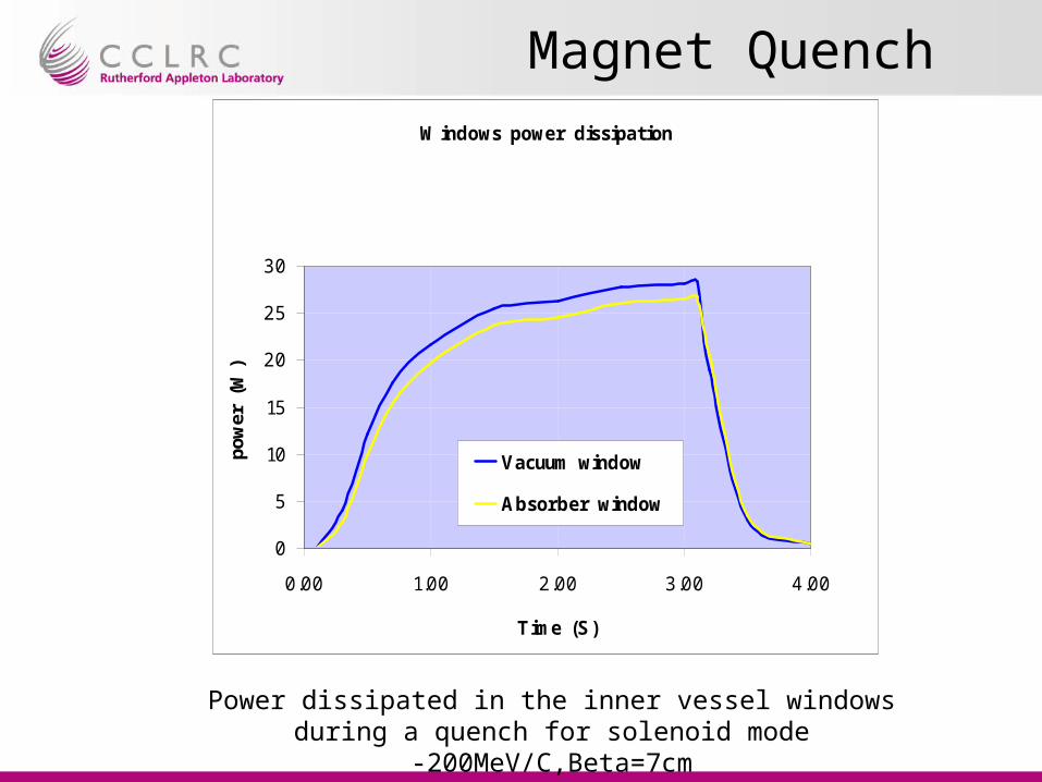
Magnet Quench
Power dissipated in the inner vessel windows during a quench for solenoid mode -200MeV/C,Beta=7cm
Windows power dissipation
0
5
10
15
20
25
30
0.00 1.00 2.00 3.00 4.00
Time (S)
pow
er (
W)
Vacuum window
Absorber window

Magnet Quench
Power dissipated in the inner vessel bodies during a quench for solenoid mode -200MeV/C,Beta=7cm
Window holder power dissipation
0
5000
10000
15000
20000
25000
0.00 1.00 2.00 3.00 4.00
Time (S)
pow
er (
W)
Vacuum body
Absorber body
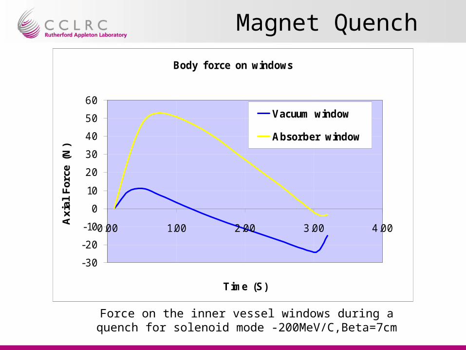
Magnet Quench
Force on the inner vessel windows during a quench for solenoid mode -200MeV/C,Beta=7cm
Body force on windows
-30
-20
-10
0
10
20
30
40
50
60
0.00 1.00 2.00 3.00 4.00
Time (S)
Axia
l For
ce (
N)
Vacuum window
Absorber window

Conclusions
–Magnetic Forces
Static – internal/external force management is well understood – no significant interaction with absorber
Quench – coil body forces understood and controlled within magnet cryostat
–Quench –eddy current
forces on windows very small cf vacuum/liquid loads
power generated in absorber bodies and windows will not cause significant pressure rise/liquid boil off
–Impact on absorber design and safety –– no special design requirements for magnet interactions


![[Mac Elwyn Van Valkenburg] Network Analysis(BookZZ.org)](https://static.fdocuments.net/doc/165x107/563db964550346aa9a9ce8aa/mac-elwyn-van-valkenburg-network-analysisbookzzorg.jpg)