MI Uzi Submachine Gun
25
OPERATION MANUAL Cal. 9 mm PARABELLUM FABRIQUf NATIONAU GAMS BE SUEHRE. 5. *.. HERSTAL-LI£S£ (BELGIUM)
Transcript of MI Uzi Submachine Gun
OPERATION MANUAL
Cal. 9 mm PARABELLUM
FABRIQUf NATIONAU GAMS BE SUEHRE. 5. *.. HERSTAL-LI£S£ (BELGIUM)

TABLE OF CONTENTS
Historical Background }
General Characteristics 5
Functioning igHandling , 17Exploded View 22-23
Zeroing 25Immediate Action And Stoppages 26
Cleaning And Maintenance 28Stripping And Assembling 30Accessories 43List Of Components 46
Hi
Historical Background
Although automatic weapons in the form of the early
Maxim, Hotchkiss and Lewis designs first appeared in the late
1800's, and one form of early machine gun was actually used
by the Confederacy during the Civil War, the submachine gun
is uniquely a 20th Century weapon, like the guided missile
and the submarine. The fust true submachine gun, the Italian
Villar Perosa, appeared in 1915. Originally designed for use in
aircract, it was quickly adapted to use by ground troops. While
it doesn't fit today's image of an SMG, it did nevertheless
presage better things to come.
Worid War I had ground to a standstill in the trenches and
probably would have ended in a negotiated settlement be-
tween the Allies and the Central Powers had the U.S. not
entered the war on the Allied side in the spring of 1917. The
British SMLE and German M98 Mauser rifles which dominated
the conflict were superb weapons for long range, deliberate
fire, but they were hardly suited to the quick, close in work
that resulted when one side decided to go "over the top" and
assault the enemy's trenches. While the U.S. relied heavily on
the Winchester M97 shotgun, the Germans went to work on
designing a compact, lightweight automatic weapon that
could be used to achieve the same results. Even while pro-
testing the "inhumane" shotgun the Americans were using,
the Germans were developing the MP-18 {Machincn Pistole
1918). The machine pistol handle was actually a misnomer,
since the MP-18 looked very much like a conventional semi-
automatic rifle. However, it was chambered for the 9mm Para-
bellum pistol cartridge, and it was capable of automatic fire,
so the term machine pistol can be justified by only a little
misguided logic. Also, it has been reported that the Germans
IVL
1
UZI SMG OPERATION MANUAL
who were developing the first true assault rifle during WorldWar il also referred to that arm as a machine pistol since
Hitler had specifically forbidden development work on whathe considered a frivolous weapon. A little of the same ration-
ale may have been applied 25 years earlier, although true
machine pistols were themselves just barely off the drawing
board at the time.
The MP-18's designers were well aware that a cartridge
more powerful than the 9mm Parabellum was needed to
make their weapon more effective, but the demands of warwere hardly conducive to spending a lot of time and moneyon R&D for a new cartridge. As a practical compromise, the
already proven 9mm was selected. In the United States, Brig.
Gen. John Thompson was also working on a submachine gun
{which he labeled a "trench broom") chambered for the .45
ACP cartridge. Despite the technological advances in arma-
ment produced by two global conflicts and numerous smaller
wars, to say nothing of the luxury of plenty of time betweenwars for R&D, the 9mm Parabellum and .45 ACP remain the
principal cartridges for use in subguns throughout the Free
World, with the former being by far the most prolific.
Although World War I ended before the MP-18 could
really be given a fair trial under actual combat conditions, thelittle evidence that was available indicated that the con-
cept of the submachine gun was well worth exploring. Ofparticular interest is the fact that the Treaty of Versailles
specifically prohibited Germany from developing and manu-facturing submachine guns and equipping her token armythat the treaty permitted with them. History was even moreunkind in the case of field trials for the Thompson. Accordingto an interesting hut doubtful legend, a crate of Thompsonsbound for the front lines in France arrived at New YorkHarbor on November 11, 1918 — the very day the armistice
was signed
,
Although General Thompson continued working on his
dream which would eventually be known worldwide as the
"Tommy Gun", SMG development was, for all intents andpurposes, a dead issue in the United States and Britian. Suchwas not the case in Europe, however, and numerous con-
UZI SMG OPERATION MANUAL
tinental arms firms were experimenting wth different designs,
all of which bore a stronger resemblance to semi-auto rifles
than to the submachine gun as we know it today. These guns
received their first real tests during the Spanish Civil War,
along with a lot of German and Soviet aircraft which wouldbe the mainstays during the opening battles of World War II.
Subguns proved to be especially well suited to house to housefighting and firefights in forested areas. As war clouds
loomed over Europe in the closing days of the 1930's andeveryone became painfully aware of the fact that German re-
armament was hardly of a strictly defensive nature, the
United States and Britain continued to ignore the need for
submachine gun development.
On the morning of September 1, 1939, the world awak-
ened to war borne by the screaming cry of Stukas diving
toward Polish cities below. That war would officially end six
years and one day later on the deck of an American battle-
ship anchored in Tokyo Bay. During those six years, the
submachine gun proved its value in war from the steaming,
malaria-infested jungles of New Guinea to the icy streets of
Stalingrad. Successive SMG designs began to evolve into the
classic profile we know today — a large, detachable boxmagazine, a short barrel and collapsible buttstock. TheAmerican M3 "Grease Gun" is a perfect example of the
type of weapons that emerged from the conflict.
The Israeli Uzi is what is known as a "second generation"
SMG, being somewhat shorter and lighter than its predeces-
sors. It was designed by Israel Galili, who borrowed heavily
from several of the better Czechoslovakian designs, especially
in his use of the telescoping bolt. Galili can hardly be con-
demned for copying the Czechs so closely. After all, it makesfar more sense to copy what works than to waste time onoriginality which may or may not produce the desired result.
Galili added a few refinements of his own and came upwith the Uzi, which is believed by many to be the finest sub-
machine gun in the world. First adopted for service in 1950,it has been the standard SMG in the numerous Arab-Israeli
conflicts ever since. Originally equipped with a wooden butt-
stock, it is now normally equipped with a collapsible metal
UZI SMG OPERATION MANUAL
stock, although the wooden one is available as an accessoryitem. Due to the constant demand for Uzi's, they are madeunder license by the FN ptant in Belgium as well as by Israeli
Military Industries. The Uzi is a favorite of the AmericanSecret Service and has been adopted by the military of anumber of Free World nations. Indeed, the Uzi and GordonIngram's MAC 10 are the SMG's by which ail others are
judged.
Since the infamous Gun Control Act of 1968 prohibits
American civilians from owning foreign-made, fully auto-
matic Uzi's, a semi-auto version was introduced in this
country in 1980. Within months, several enterprising firmswere manufacturing parts which could be used to convertthe semi-auto guns to full auto (legal with prior BATF appro-val). At least three books have also been written on the sub-
ject. Other than the obvious differences in the select lever,
etc., the weapons are essentially the same whether semi- orfull auto and are handled and field stripped in the samemanner.
Although some ordnance experts are heralding the shot-
gun as the up and coming Individual military weapon, it is
doubtful if the submachine gun will ever totally disappearfrom the action spots of the world, even should hand heldlaser guns become a reality in the near future. Whether in
its original "home grown" IMI version or of F.N. parentage,
you can expect to see the Uzi in action for a long time tocome.
The material that follows has been adapted from the
original factory manual published by FN. Since Us publica-
tion, the cocking knob has been enlarged and the selector
modified. The latter was necessary since the original selector
would permit an occasional, random burst of full auto fire
when it was set on semi-auto.
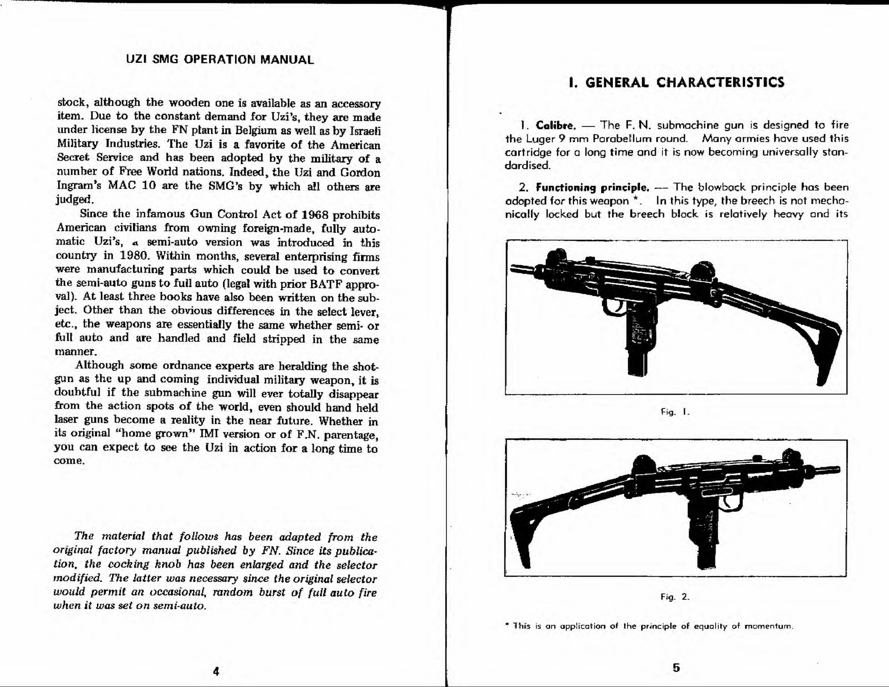
I. GENERAL CHARACTERISTICS
1. Calibre, — The F. N. submachine gun is designed to fire
the Luger 9 mm Parabellum round. Many armies have used this
cartridge for a long time and it is now becoming universally stan-
dardised.
2. Functioning principle, — The blowback principle has been
adopted for this weapon *. In this type, the breech is not mecha-
nically locked but the breech block is relatively heavy and its
»
^^B --'
Fig. I.
Fig. 2.
Thfs is an -application of the principle oF equality of momentum
UZI SMG OPERATION MANUAL
mass prevents the breech from opening effectively untH gas pres-
sure in the barrel has fallen considerably.
3. Firing.— The weapon can be fired in two ways : either semi-
automatic (single shot) or fully automatic.
The change lever is on the left side of the pistol grip. It can be
set with the thumb of the right hand when this hand is holding the
weapon.
4. Stability and hgndiness. — Careful calculation of its centre
of gravity and weight has made the weapon very steady whenfiring, which, in turn, practically eliminates any upward jerk andreduces recoil considerably.
The F. N. submachine gun is so designed that the soldier conadvance with his weapon ready to fire held in one hand, leaving
his other hand free for any contingency.
5. Feed. — Location of the magazine in the pistol grip makeschanging o magazine both simple and speedy,
6. Sights, — These consist of :
A diopter rearsight, which can be tilted for settings correspond-ing to distances of 100 and 200 metres respectively.
A blade foresight, simultaneously adjustable for height anddirection,
Both sights are provided with protectors.
The level of sight line above ground is very low, which allows
the soldier to keep well under cover when firing.
7. Safely.
device :
—
The F. N. submachine gun has a double safety
a) The automatic safety in the pistol grip, located at the rear
;
this contact safety prevents both cocking the action and firing
so long as the firer does not tighten his clasp on the pistol grip
and thus press the safety. This device prevents release of the
sear and thus any movement of the breech-block.
UZI SMG OPERATION MANUAL
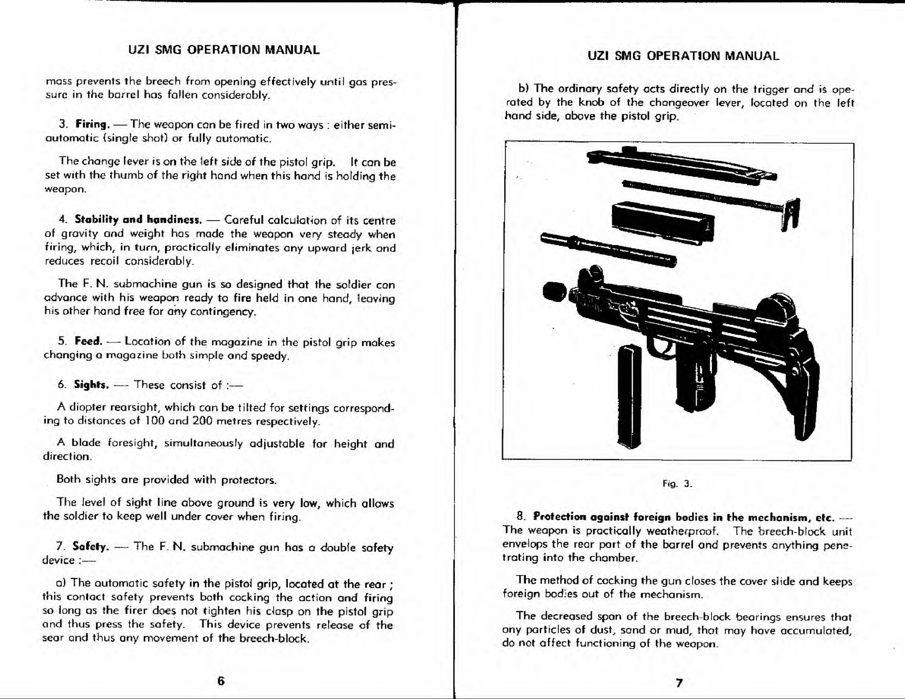
b) The ordinary safety acts directly an the trigger an<i is ope-
rated by the knob of the chongeover lever, located on the left
hand side, above the pistol grip.
Fig. 3.
8. Protection against foreign bodies in (he mechanism, ere. —The weapon is practically weatherproof. The breech-block unit
envelops the rear part of the barrel and prevents anything pene-trating into the chamber.
The method of cocking the gun closes the cover slide and keepsforeign bodies out of the mechanism.
The decreased span of the breech-block bearings ensures that
ony particles of dust, sand or mud, that may have accumulated,do not offect functioning of the weapon.

mmmm rmm^m^
UZI SMG OPERATION MANUAL
9. Stripping and assembly. — Stripping for norma] cleaning
and maintenance and reassembly can be done without using tools.
Stripping is simple and quick. Barrel, cover, breech-block unit
and main spring can be dismantled in a few seconds.
10. Butt. — The F. N. submachine gun is usually fitted with ametal butt, which can be extended, or folded into an inoperative
position, as required (see fig. 1 & 2).
A wooden butt can be supplied, if preferred (see fig. 4).
1 1 . Bayonet.
by a stud.
A small bayonet can be fixed ; this is engaged
Fig. 4
^tf
^flHi^lHHIHHIiH^^^^^^^^HFig. 5
8
UZI SMG OPERATION MANUAL
12 Statistical data.
Weight.
Gun, without magazine :
—
a) whit metal butt :
b) with wooden butt :
"Standard" magazine, empty:
"Standard" magazine with 25 rounds :
Overall length oi gun.
a) With metal butt extended : approx.
b) With metal butt folded : approx.
c) With wooden butt : approx.
Barref.
Length ; 260 mm (10.2")
Rifling, N° of grooves : 4
Sight radios :
309 mm C1Z2").
CycfVc rafe of fire: 650 r. p. m,
Magazine,
There ore two types :
—
— "Standard" Magazine, capacity 25 rds ;
— 32-rd Magazine,
3.570 kg (7.8 lbs.)
3.500 ^ (7.7 lbs.)
0.180 kg (6 ozs,)
0.500 kg (1.1 lbs.)
650 mm (25.5")
470 mm (18.5")
635 mm (25")
Cartridge*
9 mm Parabellum Liiger.
a) Statistics ;
—
Length: 29.70 mm (1.16").
Weight: 12.10 grams (.43 ozs).
Length of bullet: 15/70 mm (.62").
Weight of bullet : 8.00 grams (.28 oz.}.
Weight of powder charge ; .40 grams (.014 oz.).
b) Ballislical characteristics :
8-grom Bullet 7.5 gram Bullet
Initial Velocity (VoJ
Velocity at 12.5 m (V. 12.5)
Muzzle Energy (Eo)
Maximum Pressure
Effective range
400 m/s.
(1312 fr./sec.)
390 m/s.{1279 Fr./sec.)
65 fe-gm.
(470 ft. -lbs.)
425 m/s.(1394 ff./sEc.)
415 m/s.(1361 Fr./sec.)
69 kgm.(499 ft.-lbs.)
2500 kg/cm2 135,558 Ibs./sq.in.)
up to 200 metres (218 yds.)
II. FUNCTIONING
Firing Cycie.
The gun is loaded and cocked, i. e. the breech-block is held in
the rear position by the sear,
1 Forward movement of the breech-block.
The action of pressing the trigger causes the sear to releasethe breech-block, which is pushed forward by the return spring.
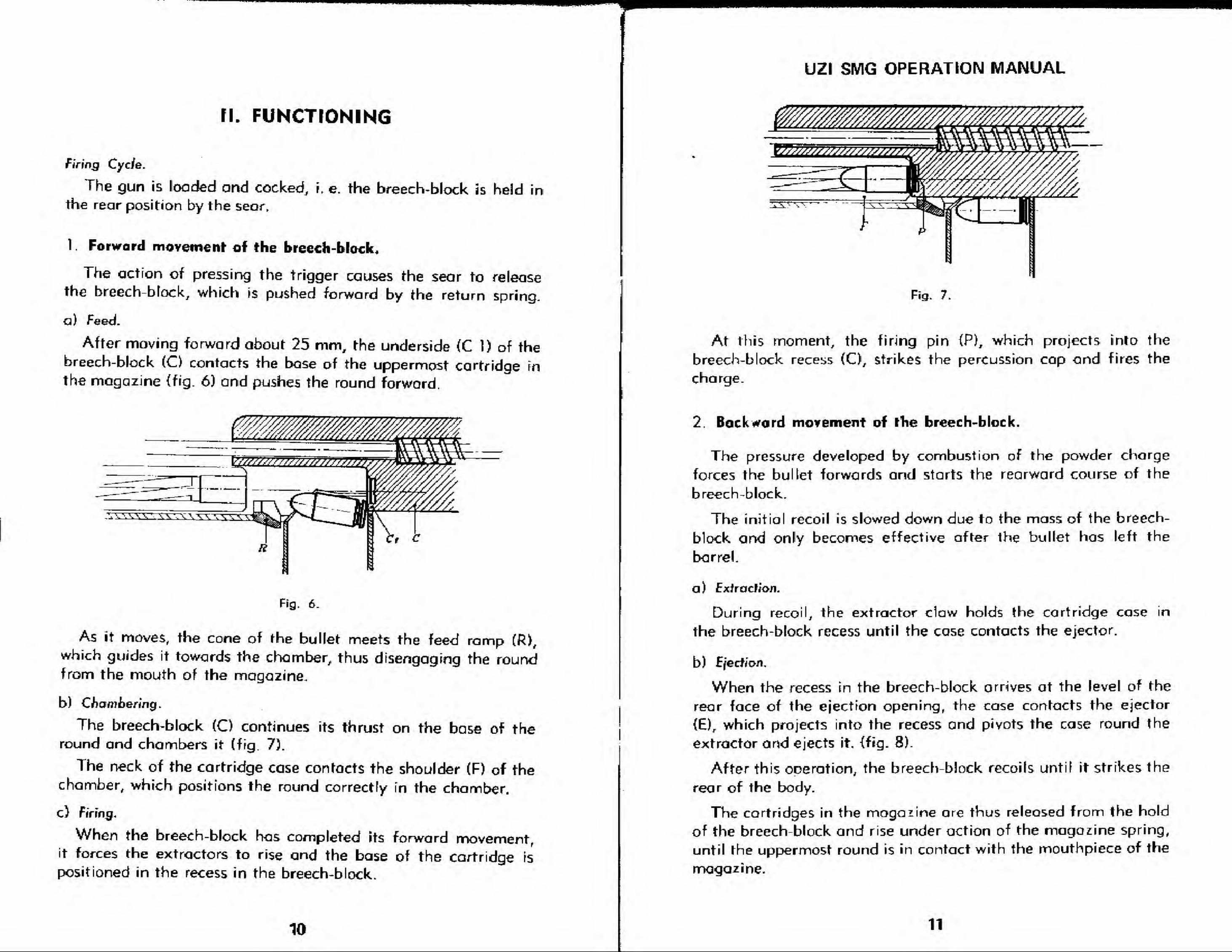
a) Feed.
After moving forward about 25 mm, the underside (C 1) of thebreech-block (O contacts the base of the uppermost cartridge mthe magazine (fig. 6) and pushes the round forword,
Fig. 6.
As it moves, the cone of the bullet meets the feed rarnp (R)t
which guides it towards the chamber, thus disengaging the roundfrom the mouth of the magazine.
b) Chambering.
The breech-block (C) continues its thrust on the base of theround and chambers it (fig. 7).
The neck of the cartridge case contacts the shoulder (F) of thechamber, which positions the round correctly in the chamber.
c) Firing..
When the breech-block has completed its forward movement,it forces the extractors to rise and the base of the cartridge is
positioned in the recess in the breech-block.
10
UZI SMG OPERATION MANUAL
Fig. 7.
At this moment, the firing pin iP), which projects rnlo the
breech-block recess (C), strikes the percussion cap ond fires the
charge.
2, Backward movement of the breech-block.
The pressure developed by combustion of the powder charge
forces the bullet forwards and starts the rearward course of the
breech-block.
The initial recoil is slowed down due to the mass of the breech-
block and only becomes effective after the bullet has left the
barrel.
a ) Extraclion.
During recoil, the extractor claw holds the cartridge case in
the breech-block recess until the case contacts the ejector.
b
)
Ejection.
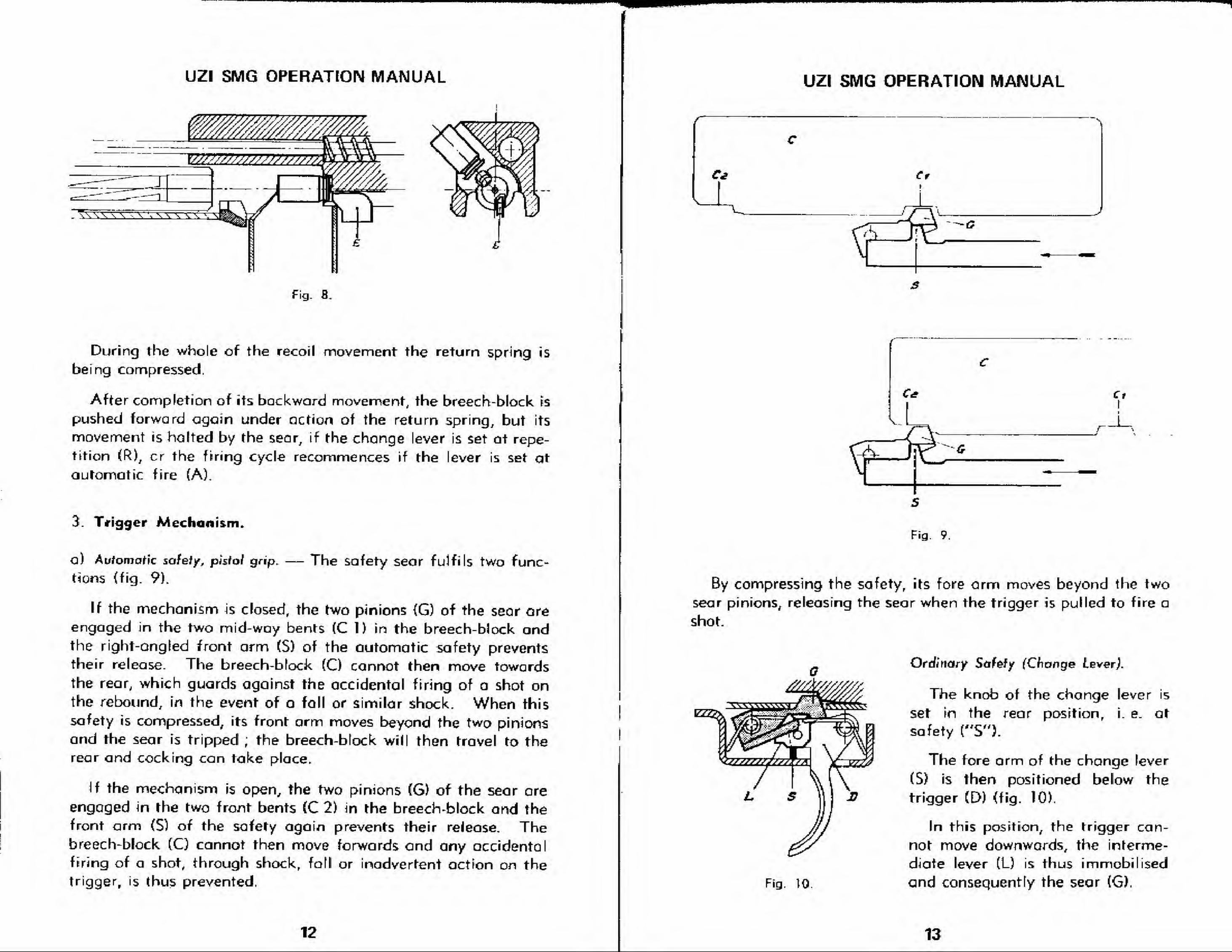
When the recess in the breech-block arrives at the level of the
rear face of the ejection opening, the case contacts the ejector
(E), which projects into the recess and pivots the case round the
extractor and ejects it. {fig. 8).
After this operation, the breech block recoils until it strikes the
rear of the body.
The cartridges in the magazine are thus released from the hold
of the breech-block and rise under action of the magazine spring,
until the uppermost round is in contact with the mouthpiece of the
magazine.
11
mm
UZI SMG OPERATION MANUAL
VJ/?//JW//>/777777<
. w\\ \ \ -, \ 'i '-, \ \ s -\,
Fig. 8
During the whole of the recoil movement the return spring is
being compressed.
After completion of its backward movement, the breech-block is
pushed forward again under action of the return spring, but its
movement is halted by the sear, if the change lever is set at repe-
tition (R), cr the firing cycle recommences if the lever is set at
automatic fire (A).
3. Trigger Mechanism.
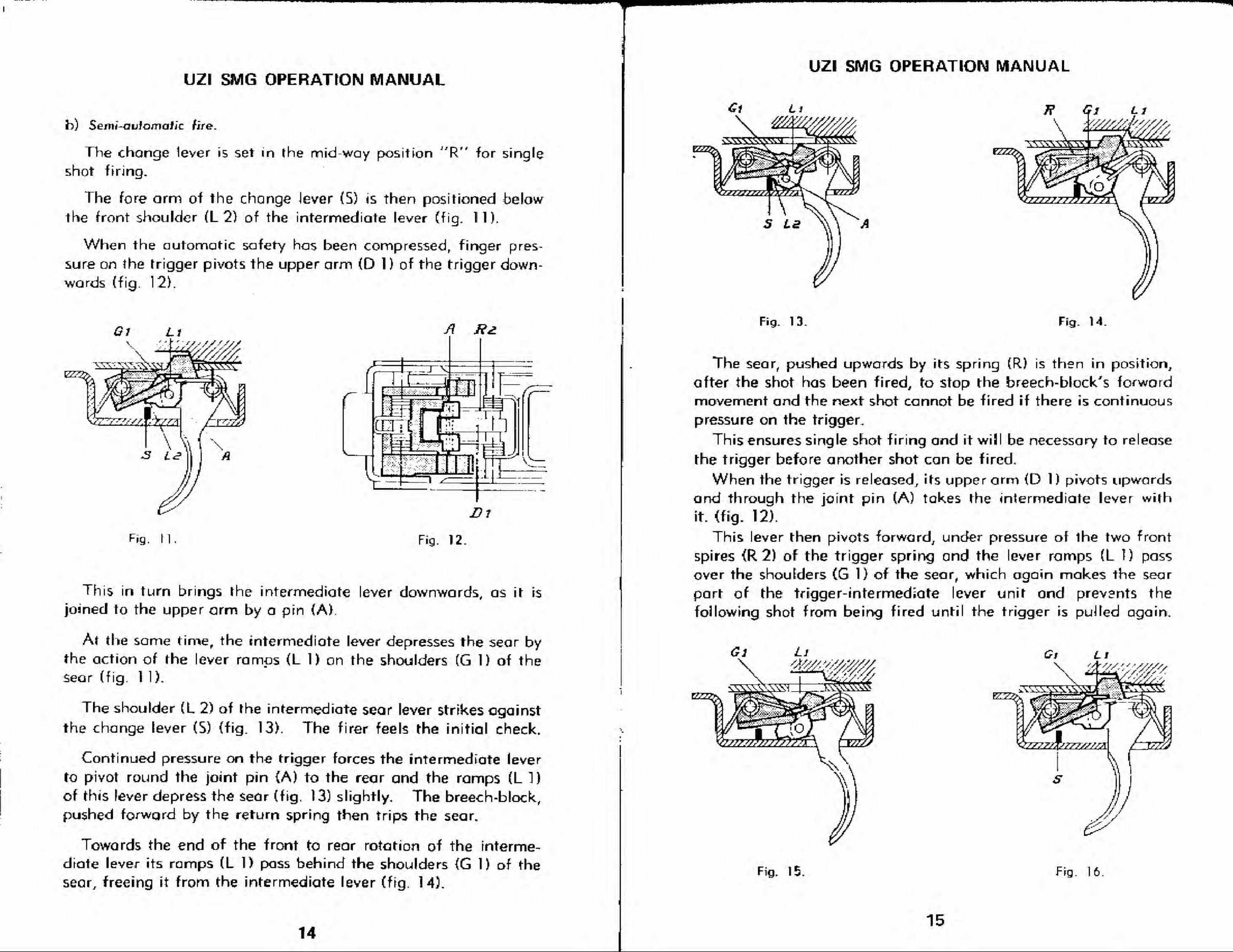
a) Automatic safely, pisiol grip,
tions (fig. 9).
The safety sear fulfils two func-
If the mechanism is closed, the two pinions (G) of the sear areengaged in the two mid-way bents (CD in the breech-block andthe right-angled front arm (S) of the automatic safety prevents
their release. The breech-block (Q cannot then move towards
the rear, which guards against the accidental firing of a shot onthe rebound, in the event of a fall or similar shock. When this
safety is compressed, its front arm moves beyond the two pinions
and the sear is tripped ; the breech-block will then travel to therear and cocking can take place.
If the mechanism is open,, the two pinions (6) of the sear areengaged in the two front bents (C 2) in the breech-block and the
front arm (S) of the safety again prevents their release. Thebreech-block (Q cannot then move forwards and any accidentalfiring of a shot, through shock, foil or inadvertent action on thetrigger, is thus prevented,
12
UZI SMG OPERATION MANUAL
•
Ce Cri
r
CtI
_i_
Fig. 9,
By compressing the safety, its fore arm moves beyond the two
sear pinions, releasing the sear when the trigger is pulled to fire a
shot.
Ordinary Scifsfy (Change Lever!
The knob of the change lever is
set in the rear position, i. e. at
safety ("S").
The fore arm of the change lever
(5) is then positioned below the
trigger (D) (fig. 10).
In this position, the trigger can-
not move downwards, the interme-
diate lever (L) is thus immobilised
and consequently the sear (G),Fig. tO.
13
UZI SMG OPERATION MANUAL
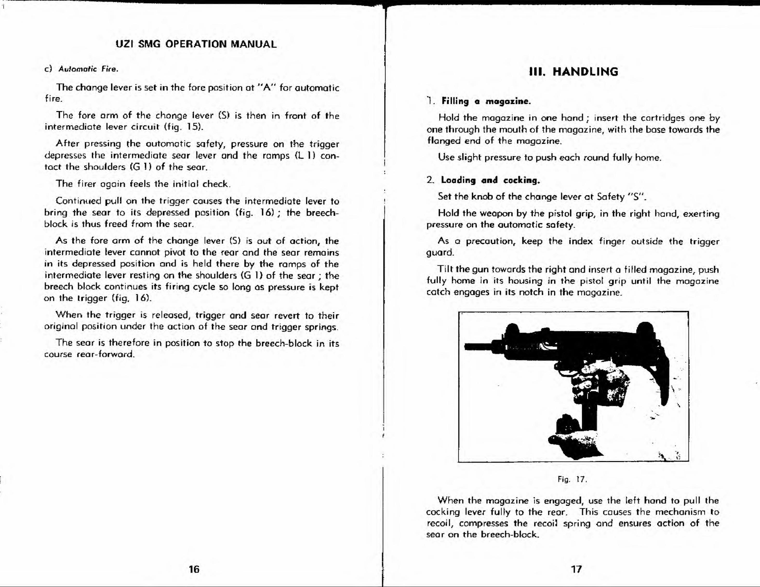
b) Serni-avlomatic fire.
The change lever is set in the midway positionJ
'R" for single
shot firing.
The fore arm of the change Jever (5) is then positioned below
the front shoulder (L 2) of the intermediate lever (fig. 11).
When the automatic safety has been compressed, finger pres-
sure on }he trigger pivots the upper arm (D 1 ) of the trigger down-wards (fig. 12).
E2E
A Rd.
Bl
Fig. H. Fig. 12.
This in turn brings the intermediate lever downwards, os it is
joined to the upper arm by a pin (A)
At the same time, the intermediate lever depresses the sear bythe action of the lever romps (L 1) on the shoulders (G 1) of the
sear (fig. 1 1).
The shoulder (L 2) of the intermediate sear lever strikes against
the change lever (5) (fig. 13). The firer feels the initial check.
Continued pressure on the trigger forces the intermediate lever
to pivot round the joint pin (A) to the rear and the ramps (L 1)
of this lever depress the sear (fig. 13) slightly. The breech-block,
pushed forward by the return spring then trips the sear.
Towards the end of the front to rear rotation of the interme-
diate lever its ramps (L 1) pass behind the shoulders {G 1) of the
sear, freeing it from the intermediate lever (fig. 14).
UZI SMG OPERATION MANUAL
Fig. 13. Fig. 14.
The sear, pushed upwards by its spring (R) is then in position,
after the shot has been fired, to stop the breech-block's forword
movement and the next shot cannot be fired if there is continuous
pressure on the trigger.
This ensures single shot firing and it will be necessary to release
the trigger before another shot can be fired.
When the trigger is released, its upper arm (D 1) pivots upwardsand through the joint pin (A) takes the intermediate lever with
it. (fig. 12).
This lever then pivots forward, under pressure of the two front
spires <R 2) of the trigger spring and the lever ramps (L I) pass
over the shoulders (G 1) of the sear, which again makes the sear
part of the trigger-intermediate lever unit and prevents the
following shot from being fired until the trigger is puJfed again.
14
-syvm
Fig. 15. Fig. 16
15
UZI SMG OPERATION MANUAL
c) Automatic Fire.
The change lever is set in the fore position at "A" for automaticfire.
The fore arm of the chonge lever (S) is then in front of the
intermediate lever circuit (fig. 15).
After pressing the qutomatic safety, pressure on the trigger
depresses the intermediate sear lever and the ramps (LI) con-
tact the shoulders (G 1 ) of the sear.
The firer again feels the initial check.
Continued pull on the trigger causes the intermediate lever to
bring the sear to its depressed position (fig. 16); the breech-
block is thus freed from the sear.
As the fore arm of the change lever (S) is out of action, the
intermediate lever cannot pivot to the rear and the sear remains
in its depressed position and is held there by the ramps of the
intermediate lever resting on the shoulders (G 1) of the sear; the
breech block continues its firing cycle so long as pressure is kept
on the trigger (fig. 16).
When the trigger is released, trigger and sear revert to their
original position under the action of the sear and trigger springs.
The sear is therefore in position to stop the breech-block in its
course rear-forward.
16
III. HANDLING
L Filling a magazine.
Hold the magazine in one hand ; insert the cartridges one byone through the mouth of the magazine, with the base towards the
flanged end of the magazine.
Use slight pressure to push each round fully home.
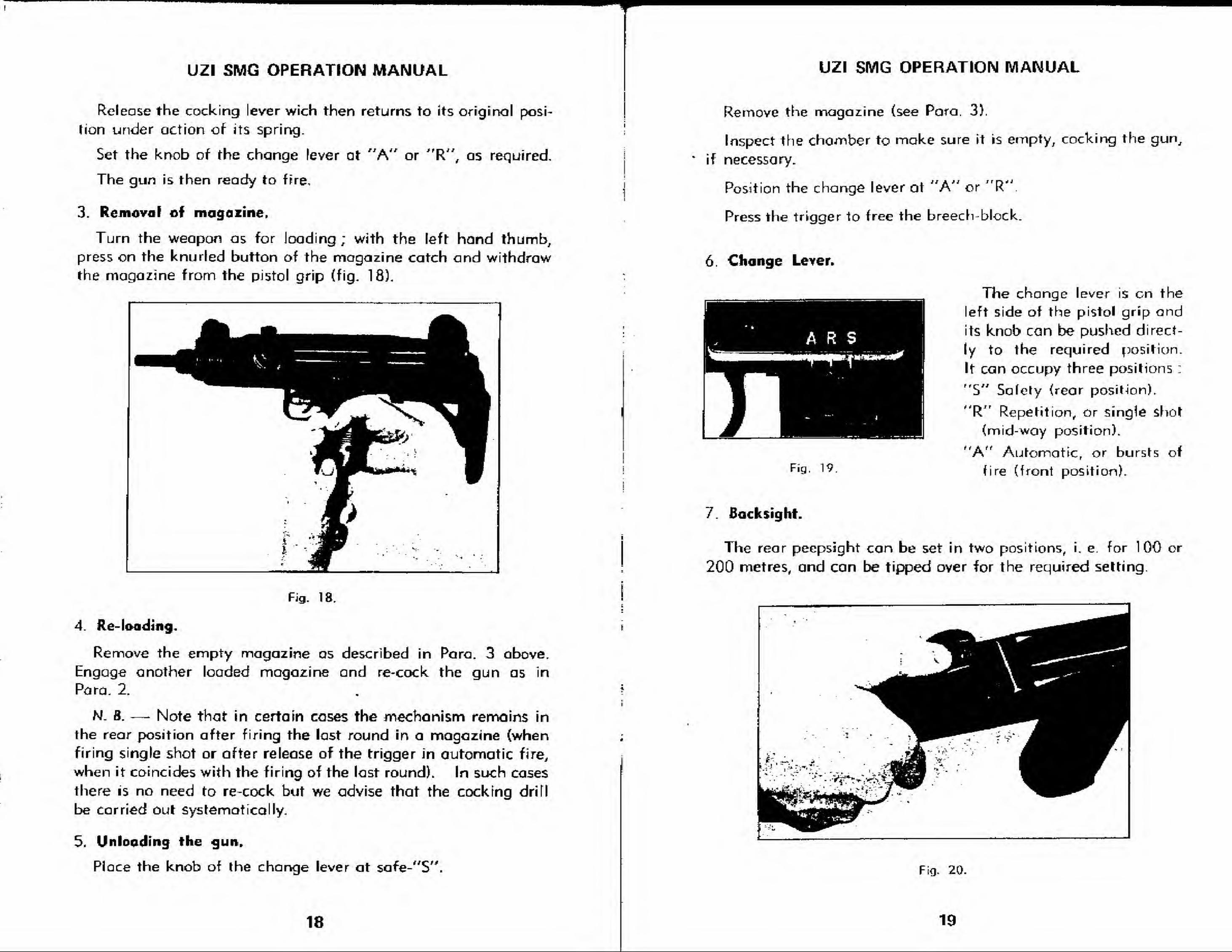
2, Loading and cocking.
Set the knob of the change lever at Safety "$".
Hold the weapon by the pfstol grip, in the right hand, exerting
pressure on the automatic safety.
As a precaution keep the index finger outside the trigger
guard.
Tilt the gun towards the right and insert a filled magazine, pushfully home in its housing m the pistot grip until the magazinecatch engages in its notch in the magazine-
Fig. 17.
When the magazine is engaged, use the left hand to pull the
cocking lever fully to the rear. This causes the mechanism to
recoil, compresses the recoi] spring ond ensures action of the
sear on the breech-block.
17
UZI SMG OPERATION MANUAL
Release the cocking lever wich then returns to its original posi-
Hon tinder action of its spring.
Set the knob of the change lever at "A" or "R", os required.
The gun is then ready to fpre,
3. Removal of magazine.
Turn the weapon as for loading ; with the left hand thumb,press on the knurled button of the magazine catch and withdraw
the magazine from the pistol grip (fig. 18).
Fig. 18,
4. Re- loading.
Remove the empty magazine os described in Para. 3 above.
Engage another loaded magazine and re-cock the gun as in
Para. 2.
N- 8. — Note that in certain cases the mechanism remains in
the rear position after firing the last round in a magazine (when
firing single shot or after release of the trigger in automatic fire,
when it coincides with the firing of the last round). In such cases
there is no need to re-cock but we advise that the cocking drifl
be carried out systematically.
5. Unloading the gun.
Place the knob of the change lever at safe^'S".
18
UZI SMG OPERATION MANUAL
Remove the magazine (see Para, 3).
Inspect the chamber to make sure it is empty, cocking the gun,
if necessary.
Position the change lever at "A" orJr
R'
Press the trigger to free the breech-block.
6. Change Lever.
ARS
Fig. 19
The change lever is on the
eft side of the pistol grip and
its knob can be pushed direct-
ly to the required position.
It can occupy three positions :
5" Safety (rear position).
R Jr
Repetition, or single shot
(mid-way position).
A" Automatic, or bursts of
fire (front position).
t r r **
t *
1 . Backsight.
The rear peepsight can be set in two positions, i. e. for 100 or
200 metres, and can be tipped over for the required setting
Fig. 20
19
UZI SMG OPERATION MANUAL UZ1 SMG OPERATION MANUAL
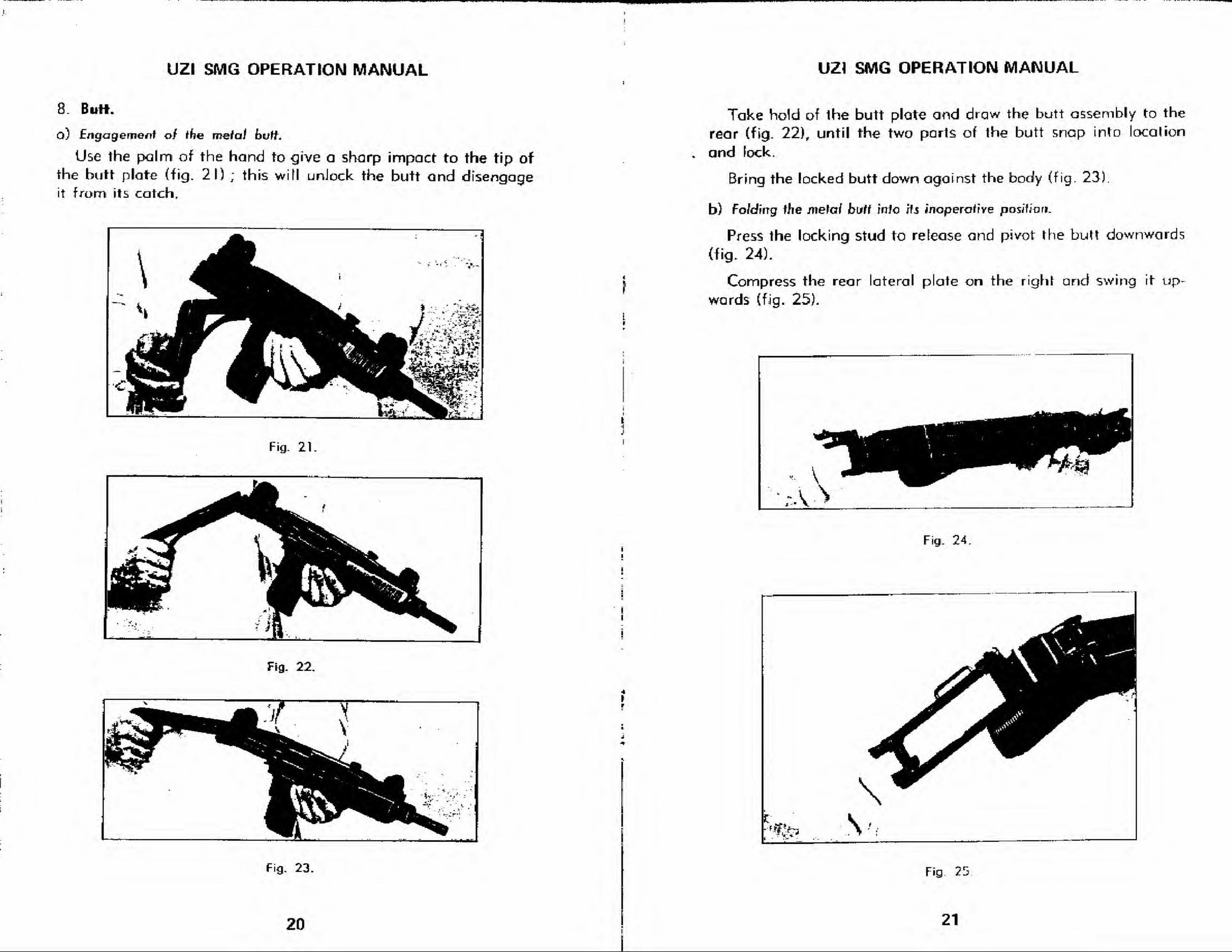
8. Butt.
o) Engagement of ihe mslai bvtt.
Use the palm of the hand to give a sharp impact to the tip of
the butt plate (tig. 21) ; this will unJock the butt and disengageit from its catch.
Fig. 21.
Fig. 22.
Fig. 23.
t
r
J
*
r
4
20
Take hold of the butt plate and draw the butt assembly to the
rear (fig. 22), until the two parts of the butt snap into local ion
and lock.
Bring the locked butt down against the body (fig. 23).
b) Fo/dirrg the me\ai butt into lis inoperative position.
Press the locking stud to release and pivot the butt downwards
(fig. 24).
Compress the rear lateral plate on the right and swing it up-
wards (fig. 25).
Fig. 24.
Fig 25
21
ir
UZI SMG OPERATION MANUAL
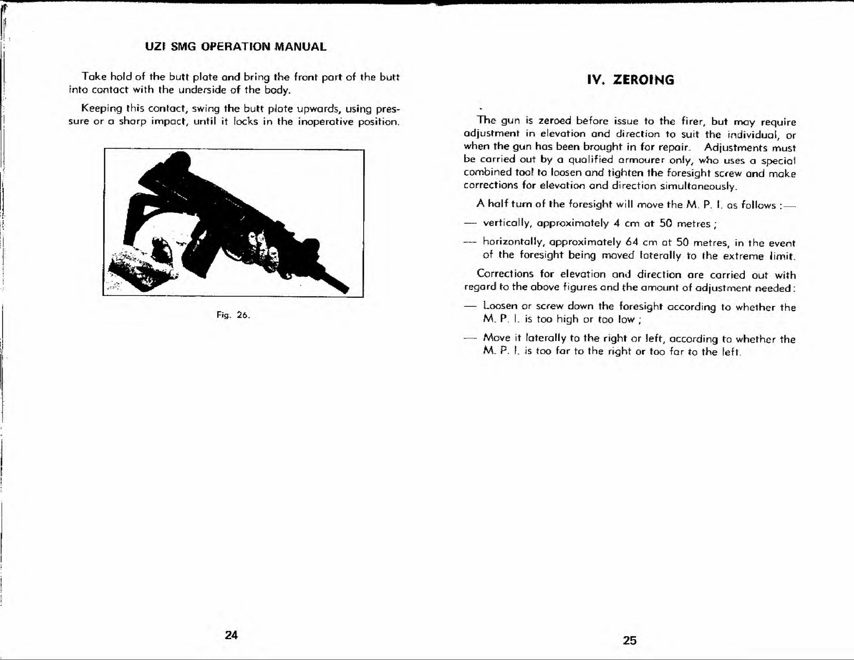
Take hold of the butt plate and bring the front part of the butt
into contact with the underside of the body.
Keeping this contact, swing the butt palate upwards, using pres-
sure or a sharp impact, until it locks in the inoperative position.
IV, ZEROING
i
Fig. 26.
The gun is zeroed before issue to the firer, but may requireadjustment in elevation and direction to suit the individual, or
when the gun has been brought in for repair. Adjustments mustbe carried out by a qualified armourer only, who uses a special
combined too? to loosen and tighten the foresight screw and makecorrections for elevation and direction simultaneously.
A half turn of Ihe foresight will move the M. P. I. as follows :
—
— vertically, approximately 4 cm at 50 metres;
— horizontally, approximately 64 cm at 50 metres, in the event
of the foresight being moved laterally to the extreme limit.
Corrections for elevation and direction are carried out withregard to the above figures and the amount of adjustment needed :
— Loosen or screw down the foresight according to whether the
M. P. I. is too high or too low;
— Move it laterally to the right or left, according to whether the
M. P. I. is too far to the right or too far to the left.
24 25
M
i
UZI SMG OPERATION MANUAL
V. IMMEDIATE ACTION AND STOPPAGES
!
f
1. Immediate action.
If the gun ceases to fire when correctly operated, there is astoppage.
This stoppage (except in the case of an empty magaiine) canoften be cleared by taking quick action, without investigating thecause of the incident.
2. Immediate action ta be taken.
Fiist action.
Operation I. — Cock the gun.
2. — Withdraw the mogozine.
3. — Replace another magazine
Operation 4. — Fire ogain
Operation
Operation
f there is still a stoppage, proceed as follows
Second action.
Operation 1
.
Operation 2,
Operation 3.
Operation 4.
Operation 5. -
Operation 6. -
3. Stoppages,
Cock the gun.
Remove the magazine.
Check thot the cartridges are correctly posi-
tioned in the magazine.
Check that there is neither a trapped cose norcartridge in the mechonism or chamber ; if this
is the cause, clear the obstruction.
Replace the magazine, pushing it fully home.
Fire ogam.
If the incident recurs systematically, check the points listed
below, after repeating the first 4 operations under ''Secondaction".
Tightness of barrel
a) Barrel locking nut loosened
b) Barrel locking catch damag-ed ;
fjrfrockKr,
a) broken
b) deformed :
c) "fouled :
Breech-bfocfc and body
ExfraclQf hvusing, breecfi-bfocfc :
ftotum spring r
Magazine cafcfi :
Trigger assembly
screw up tightly, locating the
barrel correctly.
if it is not possible to repair
immediately, tighten the barrel
locking nut periodically.
fit a new extractor.
fit a new extractor.
strip ancf clean.
carry out field stripping proce-
dure and clean the gun ; after
cleaning, the breech-block
should slide easily in the body.
clean the hollowed part care-
fully, also underneath the ex-
tractor claw.
the guide-rod must be straight :
the spring must slide en the rod
without catching.
check that it is engaging the
magazine securely and is clean.
fouling ; if there is any step-
page caused by the trigger me-chanism, if possible, fire auto-
matically ; inspect, strip andclean thoroughly, as soon as
circumstances permit.
26 27
VI. CLEANING AND MAINTENANCE
1.General observations.
It must be emphasized that all automatic weapons need careful
maintenance and that the majority of stoppages mentioned only
occur as a result of the user's negligence, or lock of knowledge of
his gun. Any weapon, wheter fully automatic or self-loading, mustalways be cleaned at the end of a day's firing, particularly after
using blank cartridges.
2 Servicing the gun.
a) Care and c/eaning by thv soid'rer.
The F N. 9 mm submachine gun need only be partially stripped
(Field stripping) for this maintenance, which consists of :
—
— passing a pullthrough, soaked in special oil, through the bore
of the barrel and repeating this several times;
— pulling two or three dry rags through until bore is clean;
— cleaning the chamber with its cleaning brush;
— cleaning the breech-block end the inside of the receiver;
—• cleaning underneath the extractor claw, without stripping it
;
—• lubricating the barrel with a lightly oiled rag
;
— slightly oiling the moving parts.
b) Semefng by the Unit Armourer.
On the other hand, it rs essential that the gun be periodically
checked by the armourer, who will ensure that it is receiving
proper care from the user.
This inspection must cover all the components of the weapon to
ensure that everything is in good working order. The armourer's
servicing will include ;
—
— stripping and cleaning the extractor;
— checking and adjusting sights, if necessary.
28
UZI SMG OPERATION MANUAL
3, Barrel Inspection.
Firstly^ the barrel must be regularly cleaned, in the mannerdescribed above, so that it is never neglected to the point where
the use of harmful abrasives, such as emery, sand or powdsred
brick, becomes necessary.
When the gun is called in for its periodical servicing, the
armourer must pay special attention to the condition of the barrel.
Where this is not satisfactory (powder deposit, burning, etc.) he
should carry out the operations listed under 1. above, i.e. the
soldier's maintenance. Before oiling, the bore must be so clean
that a piece of white flannelette comes through the barrel unsoil-
ed. Follow this by lightly oiling the bore and chamber.
Dry the outside of the barrel and then rub with a greasy rag.
If the gun is to be Joid up for a certain time, lubricate the inside
of the barrel, using a suitable barrel grease.
29
: i
UZI SMG OPERATION MANUAL
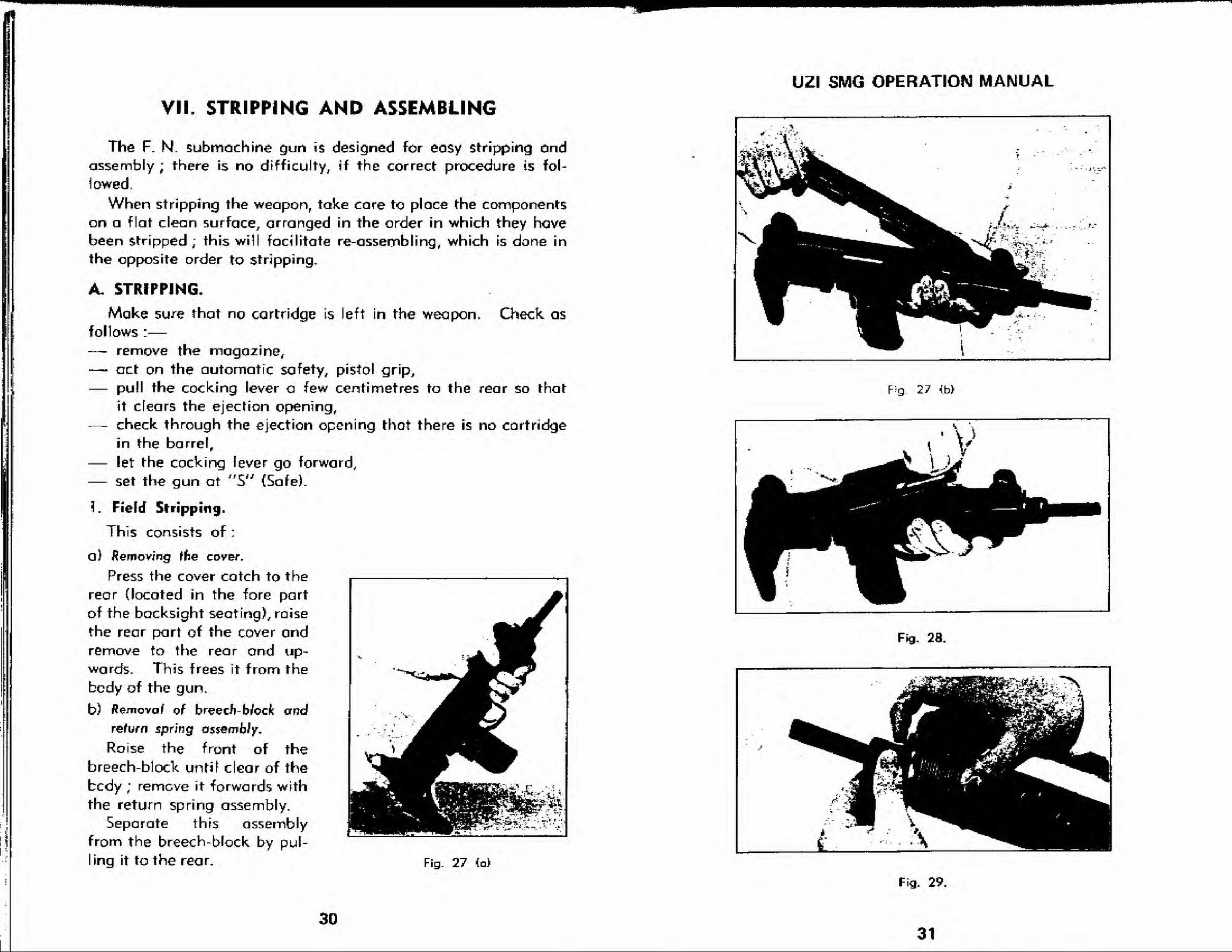
VII. STRIPPING AND ASSEMBLING
The F. N. submachine gun is designed for eosy stripping andassembly ; there is no difficulty, if the correct procedure is fol-
lowed.
When stripping the weaponFtake care to place the components
on a flat clean surface, arranged in the order in which they havebeen stripped; this will facilitate re-assembling, which is done in
the opposite order to stripping.
Check as
A. STRIPPING.
Make su-re that no cartridge is left in the weapon,follows :
—
— remove the magazine,— act on the automatic safety, pistol grip,
— pull the cocking lever a few centimetres to the rear so that
it clears the ejection opening,— check through the ejection opening that there is no cartridge
in the barrel,
— let the cocking lever go forward,
— set the gun at "5" (Safe).
I. Field Stripping.
This consists of :
a) Removing the cover.
Press the cover catch to the
rear {located in the fore part
of the backsight seating), raise
the rear part of the cover andremove to the rear ond up-
wards. This frees it from the
body of the gun.
b) fle/novaf of breech block and
return spring assembly.
Roise the front of the
breech-block until clear of the
bcdy ; remcve it forwards with
the return spring assembly.
Separate this assemblyfrom the breech-block by pul-
ling it to the rear. Fig- 27 (a)
1-* "
_
*"_" ij'TV"
"^w*'VvL-
>>4^:jTVVlL- > - ""
- r - ' - - J yE*
V*^J H 1 J -
^^^r^^B"> ^^^ /
j
-ta
- ...- .."
. . T-*
x^HB^ta^^L_T '*
»r --!.
^^^^^A^JtJ ^~*
^^^^^^
1^ * r
,\ -
\--
fig. 27 <b>
Fig. 28.
Fig. 29,
3031
A
UZI SMG OPERATION MANUAL UZI SMG OPERATION MANUAL
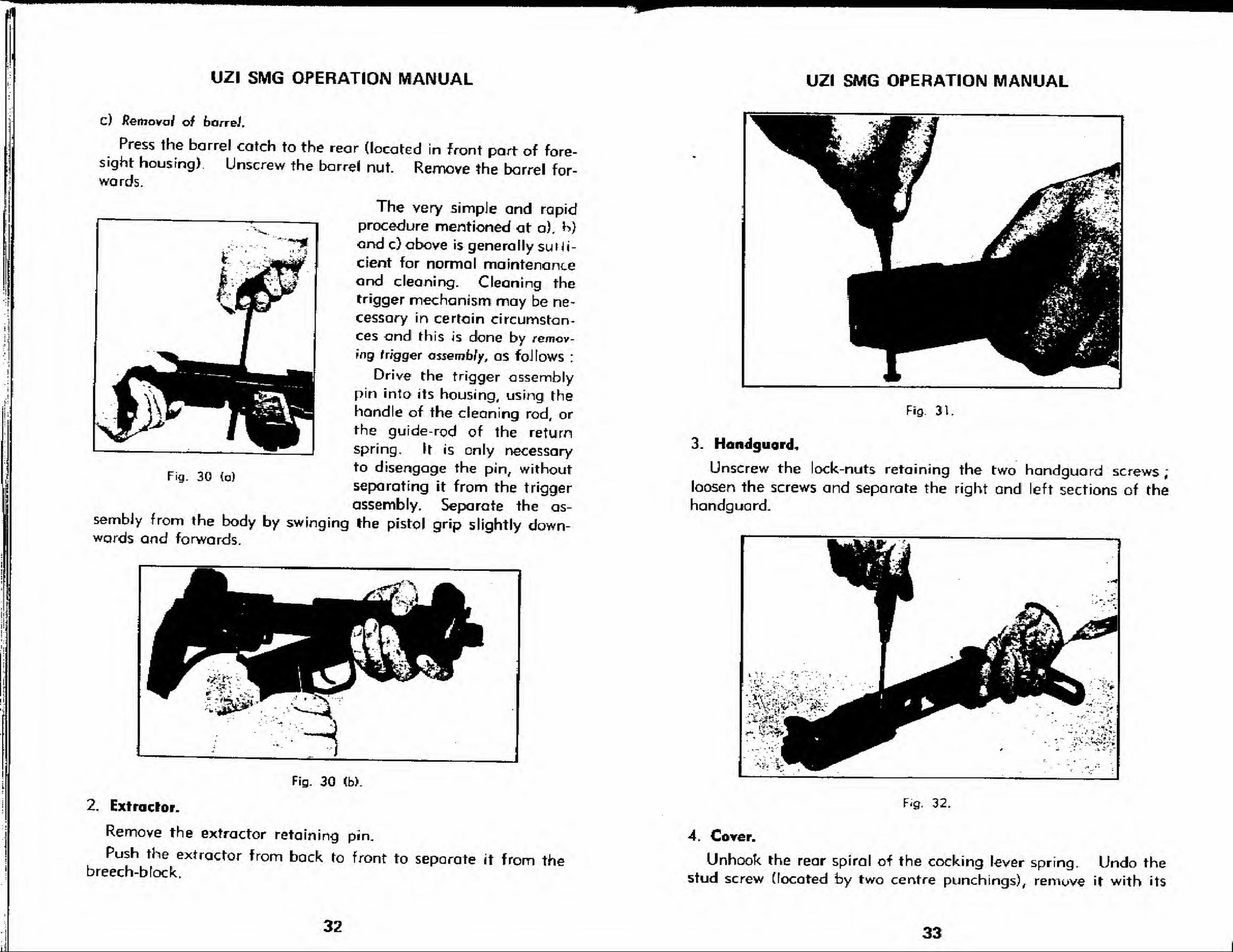
c) Removal of barrel.
Press the barrel catch to the rear (located in front part of fore-sight housing) Unscrew the barrel nut. Remove the barrel for-wards.
The very simpJe and rapid
procedure mentioned at a), h)
and c) above is generally suffi-
cient for normal maintenanceand cleaning. Cleaning thetrigger mechanism may be ne-
cessary in certain circumstan-ces and this is done by remov-
ing trigger assembly, as fallows :
Drive the trigger assemblypin into its housing, using thehandle of the cleaning rod, or
the guide-rod of the return
spring. It is only necessary
p . ,„ ., to disengage the pin, withoutFig. 30 (a) .. .. ,
r,
'
separating it from the trigger
assembly. Separate the as-sembly from the body by swinging Ihe pistol grip slightly down-wards and forwards.
Fig. 30 <b).
2. Extractor.
Remove the extractor retaining pin.
Push the extractor from back to front to separate it from thebreech-block.
Fig. 31.
3. Handguard-,
Unscrew the lock-nuts retaining the two handguard screws;
loosen the screws and separate the right and left sections of the
handguard.
Fig. 32.
4. Cover.
Unhook the rear spiral of the cocking lever spring. Undo thestud screw (located by two centre punch ings), remove it with its
32 33
UZr SMG OPERATION MANUALUZI SMG OPERATION MANUAL
i
i.
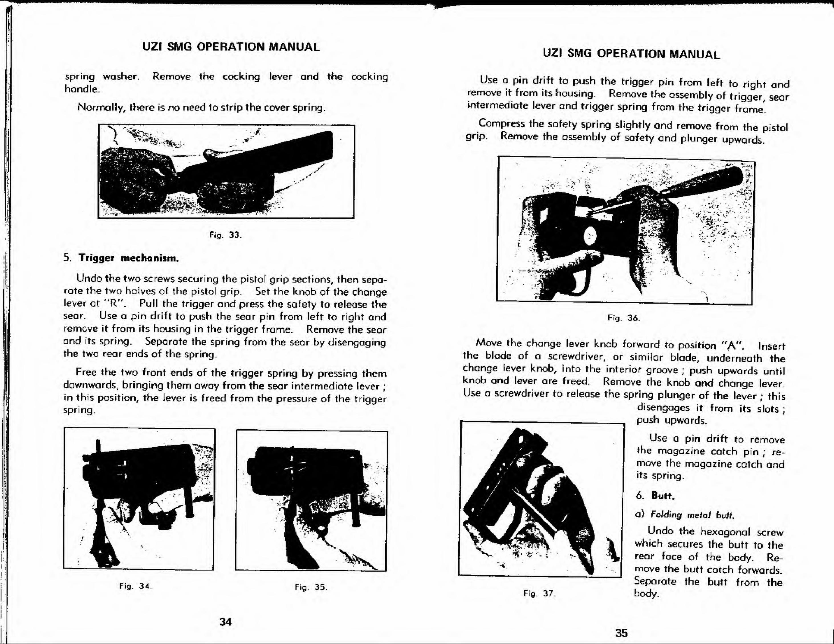
spring washer, Remove the cocking lever and the cocking
hondle.
Normally, there is no need to strip the cover spring.
^
1 - ™1
Fbw Elil
Fig. 33
5. Trigger mechanism.
Undo the two screws securing the pistol grip sections, then sepa-
rate the two halves of the pistol grip. Set the knob of the changelever at "R". Pull the trigger and press the safety to release the
sear. Use a pin drift to push the sear pin from left to right andremove it from its housing in the trigger frame. Remove the sear
and its spring. Separate the Spring from the sear by disengagingthe two rear ends of the spring.
Free the two front ends of the trigger spring by pressing themdownwards, bringing them owoy from the sear intermediate lever
;
in this position, the lever is freed from the pressure of the trigger
spring.
Use a pin drift to push the trigger pin from left to right andremove it from its housing. Remove the assembly of trigger searintermediate lever and trigger spring from the trigger frame'.
Compress the safety spring slightly and remove from the pistolgrip. Remove the assembly of safety and plunger upwards.
KT~
Fig. 34 Fig. 35.
Fig. 36.
Move the change lever knob forward to position "A". Insertthe blade of o screwdriver, or similar blade, underneath thechange lever knob, into the interior groove
; push upwards untilknob and lever are freed. Remove the knob and change lever.
Use a screwdriver to release the spring plunger of the lever ; this
disengages it from its slots;
push upwards.
Use a pin drift to removethe magazine catch pin ; re-
move the magazine catch andits spring.
6. Butt.
a) Folding metal butt.
Undo the hexagonal screwwhich secures the butt to therear face of the body. Re-move the butt cotch forwards.
Separate the butt from theFig. 37. body.
3435
UZI SWIG OPERATION MANUAL
* j
:. L~;V. V" ij,. -*-f **:,-. -
Fig. 3B
i
1
1
Fig. 39. Fig. 40.
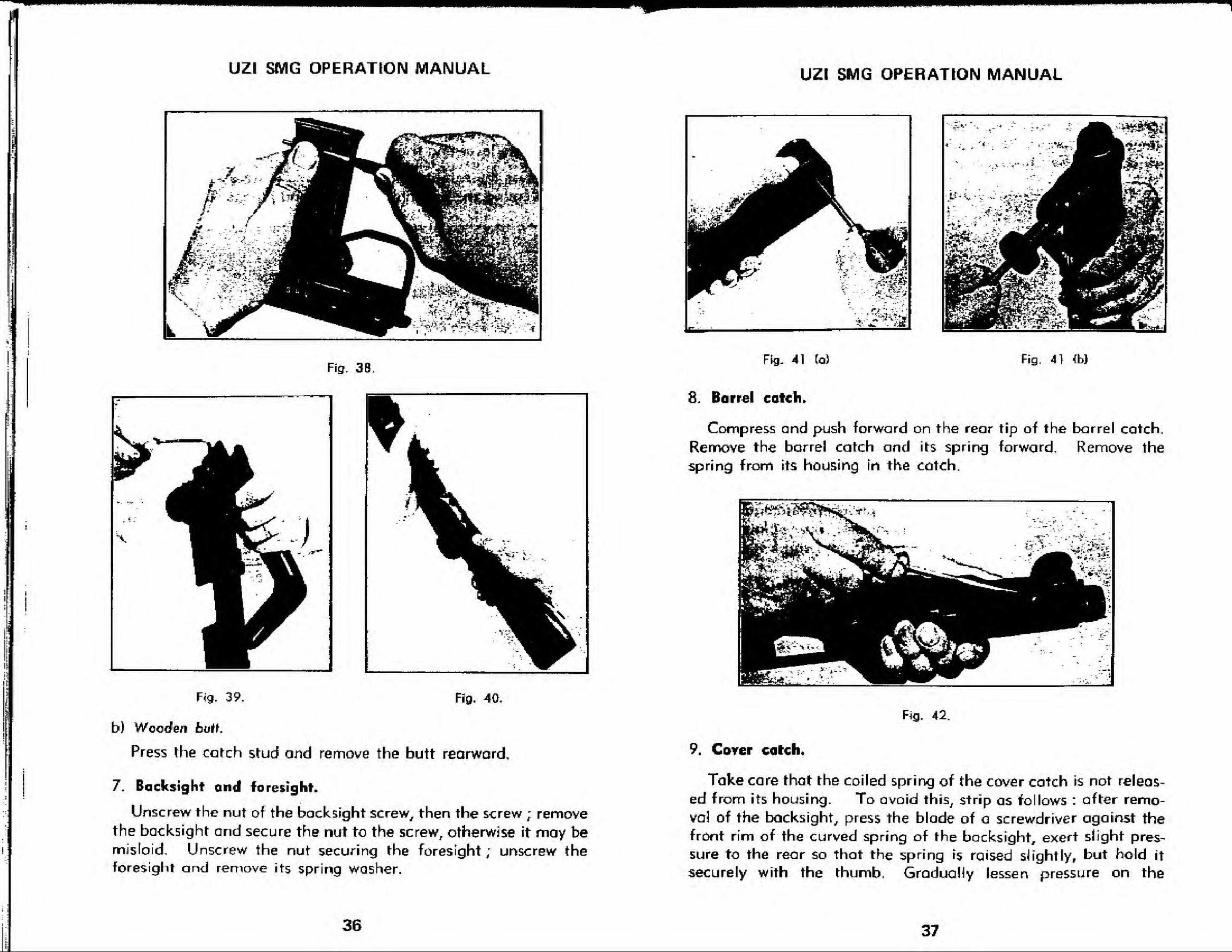
b) Wooden butt.
Press the catch stud and removG the butt rearward,
7. Backsight and foresight.
Unscrew the nut of the backsight screw, then the screw ; removethe backsight and secure the nut to the screw, otherwise it may bemistoid. Unscrew the nut securing the foresight; unscrew the
foresight and remove its spring washer.
36
UZI SMG OPERATION MANUAL
-
J*^^^. - ^ t ^v
^5 ^U^ir
' E^ ft
Fig. 41 (a) Fig. 41 <b)
8. Barrel catch.
Compress and push forward on the rear tip of the barrel catch.
Remove the barrel catch and its spring forward. Remove the
spring from its housing in the catch.
Fig. 42.
9. Carer catch,
Take care that the coiled spring of the cover catch is not releas-
ed from its housing. To avoid this, strip as follows : after remo-
val of the backsight, press the blade of a screwdriver against the
front rim of the curved spring of the backsight, exert slight pres-
sure to the rear so that the spring is raised slight ly, but hold it
securely with the thumb, Gradually lessen pressure on the
37
UZI SMG OPERATION MANUAL
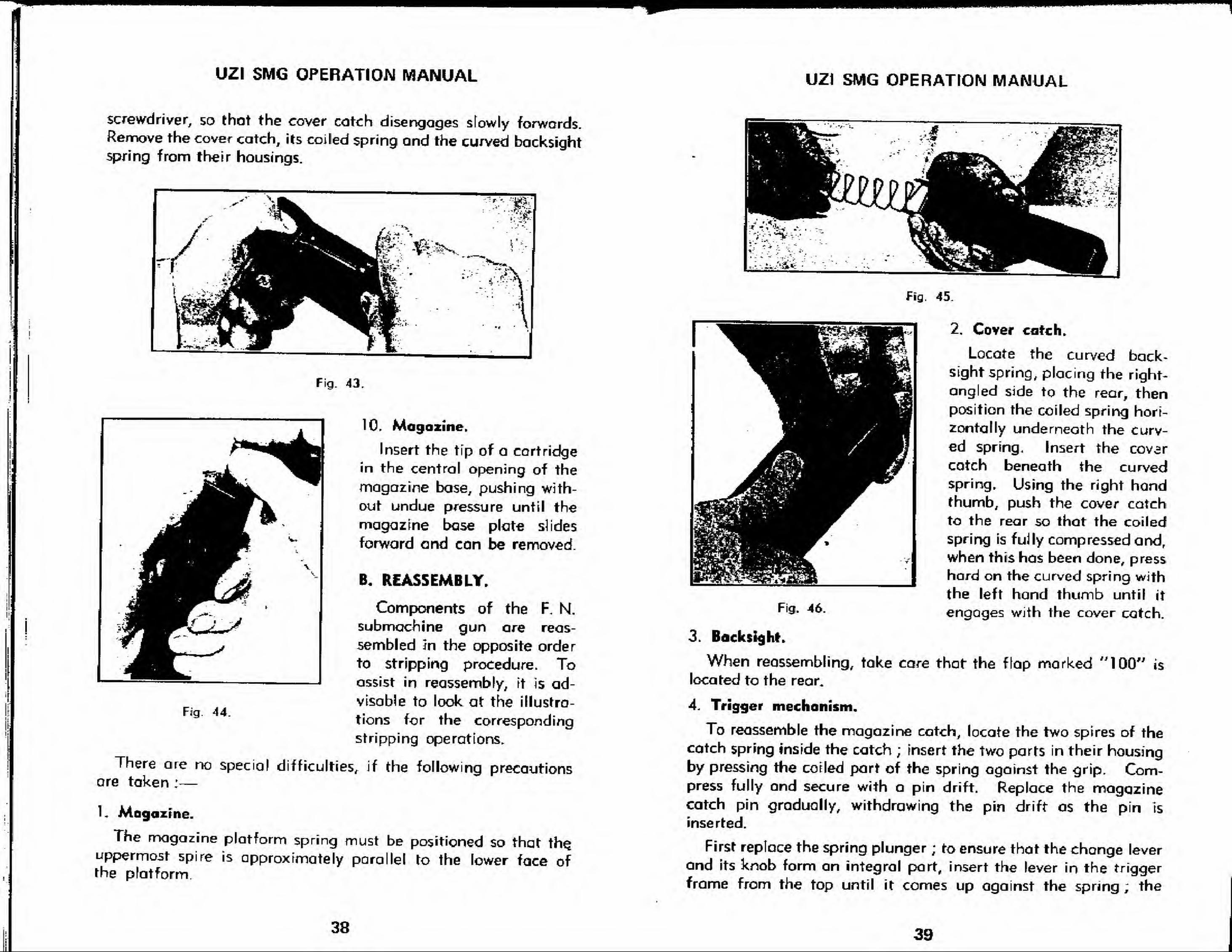
screwdriver, so thot the cover catch disengages sfowly forwards.Remove the cover catch, its coiled spring and the curved backsightspring from th-eir housings.
59-
:
T- '-
. .. A
Fig. 43.
10. Magazine.
Insert the tip of a cartridge
in the central opening of the
magazine base, pushing with-
out undue pressure until the
magazine base plate slides
forward and can be removed.
B. REASSEMBLY.
Components of the F. N.
submachine gun are reas-
sembled Jn the opposite order
to stripping procedure. Toassist in reassembly, it is ad-
visable to look at the illustra-
tions for the corresponding
stripping operations.
There are no special difficulties, if the following precautionsare taken :
—
1. Magazine.
The magazine platform spring must be positioned so that the.
uppermost spire is approximately parallel to the lower face ofthe platform.
Fig. 44.
UZI SMG OPERATION MANUAL
Fig, 45
Fig. 46.
2. Cover catch.
Locate the curved back-sight spring, placing the right-
angled side to the rear, thenposition the coiled spring hori-
zontally underneath the curv-
ed spring. Insert the cover
catch beneath the curvedspring. Using the right handthumb, push the cover catch
to the rear so that the coiled
spring is fully compressed and,
when this has been done, press
hard on the curved spring with
the left hand thumb until it
engages with the cover catch.
3. Backlight.
When reassembling, take care that the flap marked "lOO" is
located to the rear.
4. Trigger mechanism.
To reassemble the magazine catch, locate the two spires of thecatch spring inside the catch ; insert the two parts in their housingby pressing the coiled part of the spring against the grip. Com-press fully and secure with a pin drift. Replace the magazinecatch pin gradually, withdrawing the pin drift as the pin Is
inserted.
First replace the spring plunger ; to ensure that the change lever
and its knob form an integral part, insert the lever in the trigger
frame from the top until it comes up against the spring ; the
38 39
n
UZI SMG OPERATION MANUAL
!
I
Rg, 47.
-r.; X- -v
Fig. 4B.
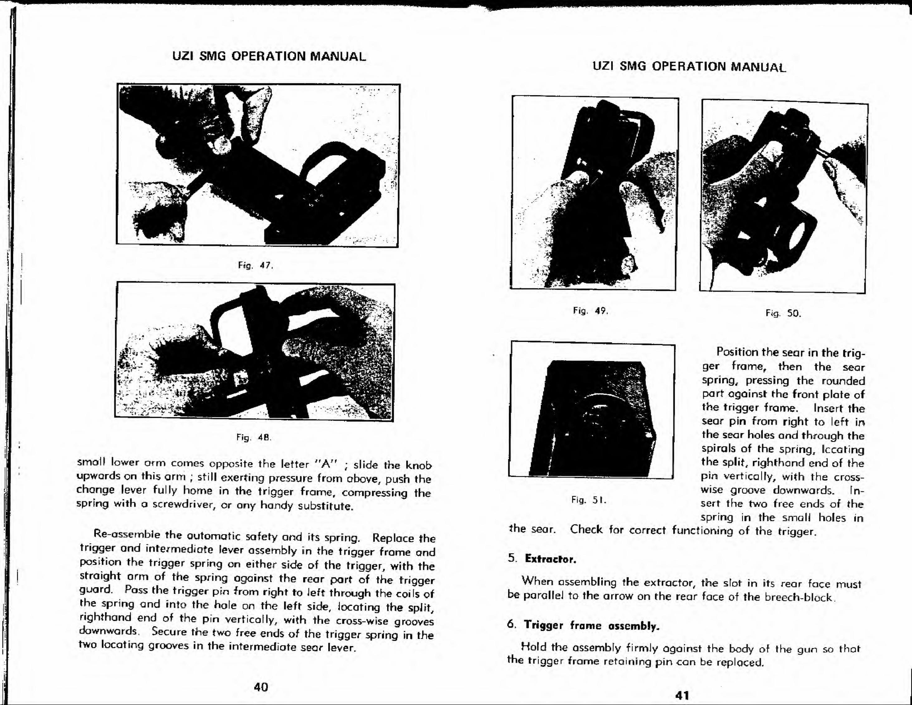
smoll lower arm comes opposite the letter "A" ; slide the knobupwards on this arm ; still exerting pressure from above, push thechange lever fully home in the trigger frame, compressing thespring with a screwdriver, or any handy Substitute.
Re-assemble the automatic safety and its spring. Replace thetrigger and intermediate lever assembly in the trigger frome andposition the trigger spring on either side of the trigger, with thestraight orm of the spring ogainst the rear part of the triggerguard. Poss the trigger pin from right to Jeft through the coils ofthe spring and into the hole on the left side, locating the split,righthand end of the pin vertically, with the cross-wise groovesdownwards. Secure the two free ends of the trigger spring in thetwo locating grooves in the intermediate sear lever.
UZI SMG OPERATION MANUAL
Fig, 49 Fig. 50
the sear.
Position the sear in the trig-
ger frame, then the sear
spring, pressing the roundedpart against the front plate of
the trigger frame. Insert the
sear pin from right to left in
the sear holes and through the
spirals of the spring, Iccating
the split, righthand end of the
pin vertically, with the cross-
wise groove downwards. In-
sert the two free ends of the
spring in the small holes in
Check for correct functioning of the trigger.
Fig. 51.
5. Extractor.
When assembling the extractor, the slot in its rear face mustbe parallel to the arrow on the rear face of the breech-block.
6. Trigger frome assembly.
Hold the assembly firmly against the body of the gun so thatthe trigger frame retaining pin can be replaced.
4041
UZf SMG OPERATION MANUAL
.- i\
-- "<* - •£ -
1
I
Fig. 52.
Fig. 53
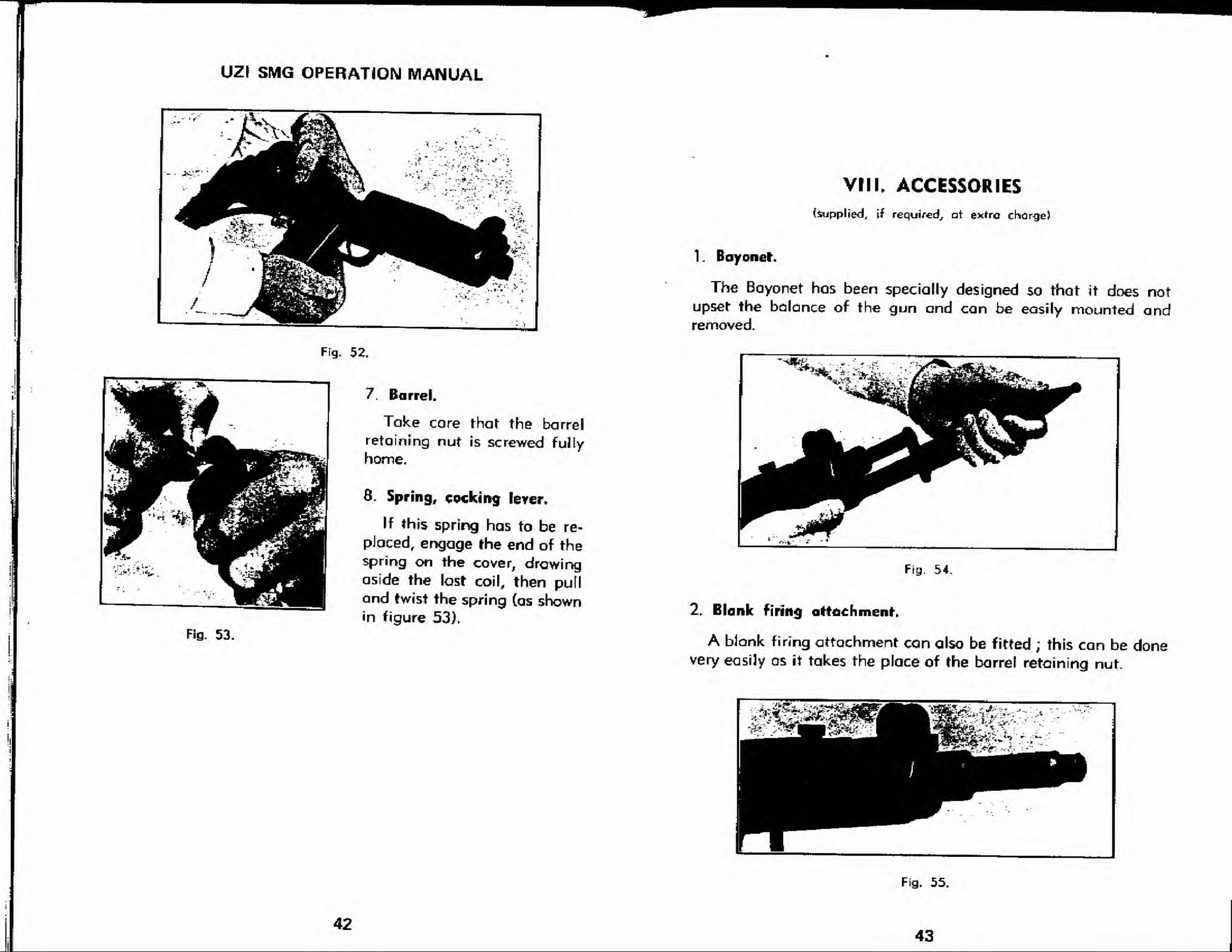
7. Barrel.
Take core that the barrel
retaining nut is screwed fully
home.
8. Spring, cocking lever.
If this spring has to be re-
placed, engage the end of thespring on the cover, drawingaside the last coil, then pulland twist the spring (as shownin figure 53).
VIII. ACCESSORIES
(supplied, if required, at exrrc change)
1 , Bayonet.
The Bayonet has been specially designed so that it does notupset the balance of the gun and can be easily mounted andremoved.
Fig. 54
2. Blank firing attachment.
A bJonk firing attachment can also be fitted ; this can be donevery easily os it takes the place of the barrel retaining nut.
!I
Fig. 55
4243
UZI SMG OPERATION MANUAL UZI SMG OPERATION MANUAL
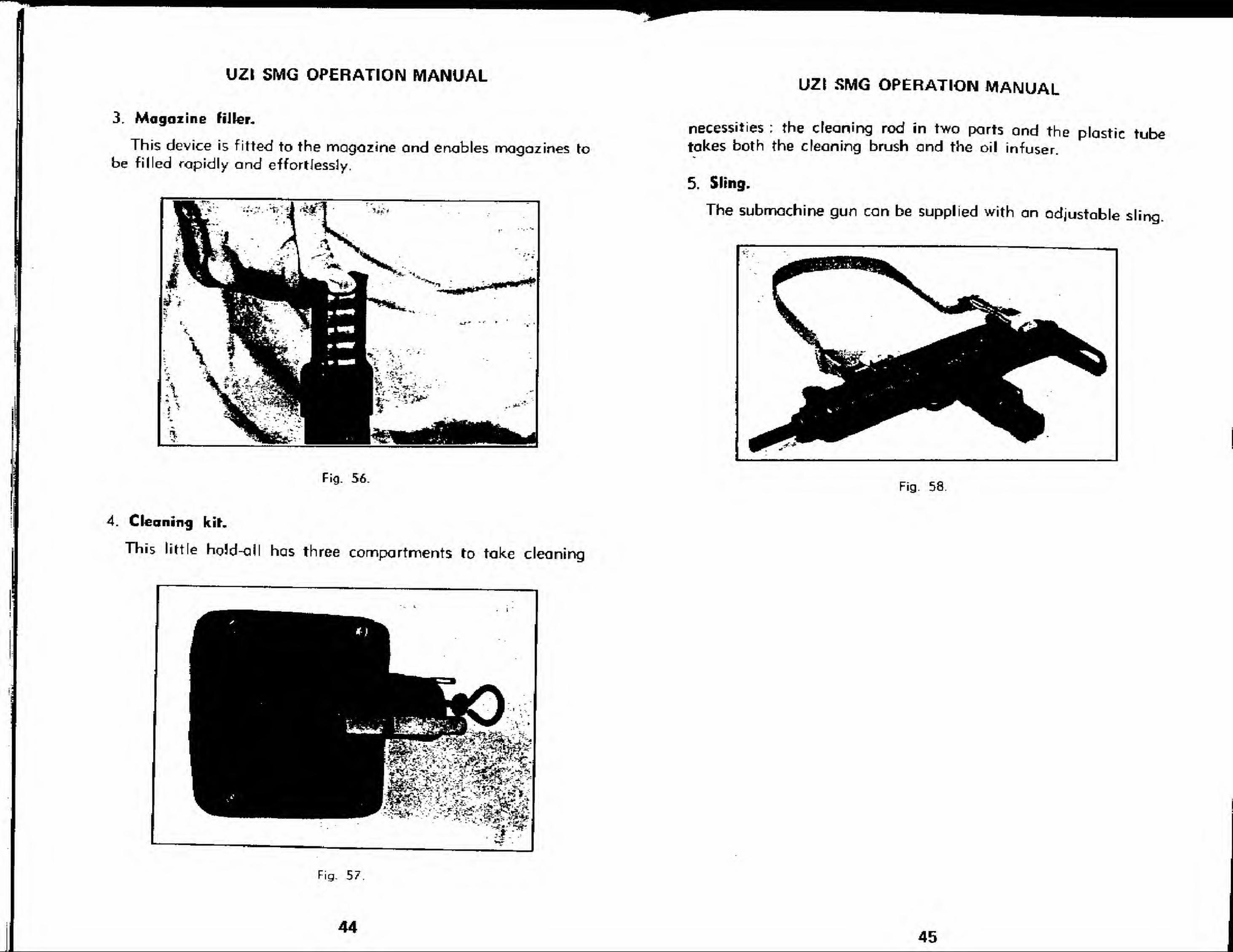
3. Magazine fiJIer.
This device is fitted to the magazine ond enables magazines to
be filled rapidly and effortlessly.
necessities : the cleaning rod in two parts ond the plastic tubetakes both the deaning brush and the oil infuser.
5. Sling.
The submachine gun can be supplied with an adjustable sling.
IH^^^^E BBHH ^^^^^^^H^HBBjMHHH^B I^^^^^^^^^^^^^^^^^^H
ii b,
^^^^^ ^^^^^- ^^B
^^B
j^t^ ^B
Fig- 56.Fig. 58.
4. Cleaning kit.
This little hgJd-aii has three compartments to take cleani ng
Fig. 57
144
45
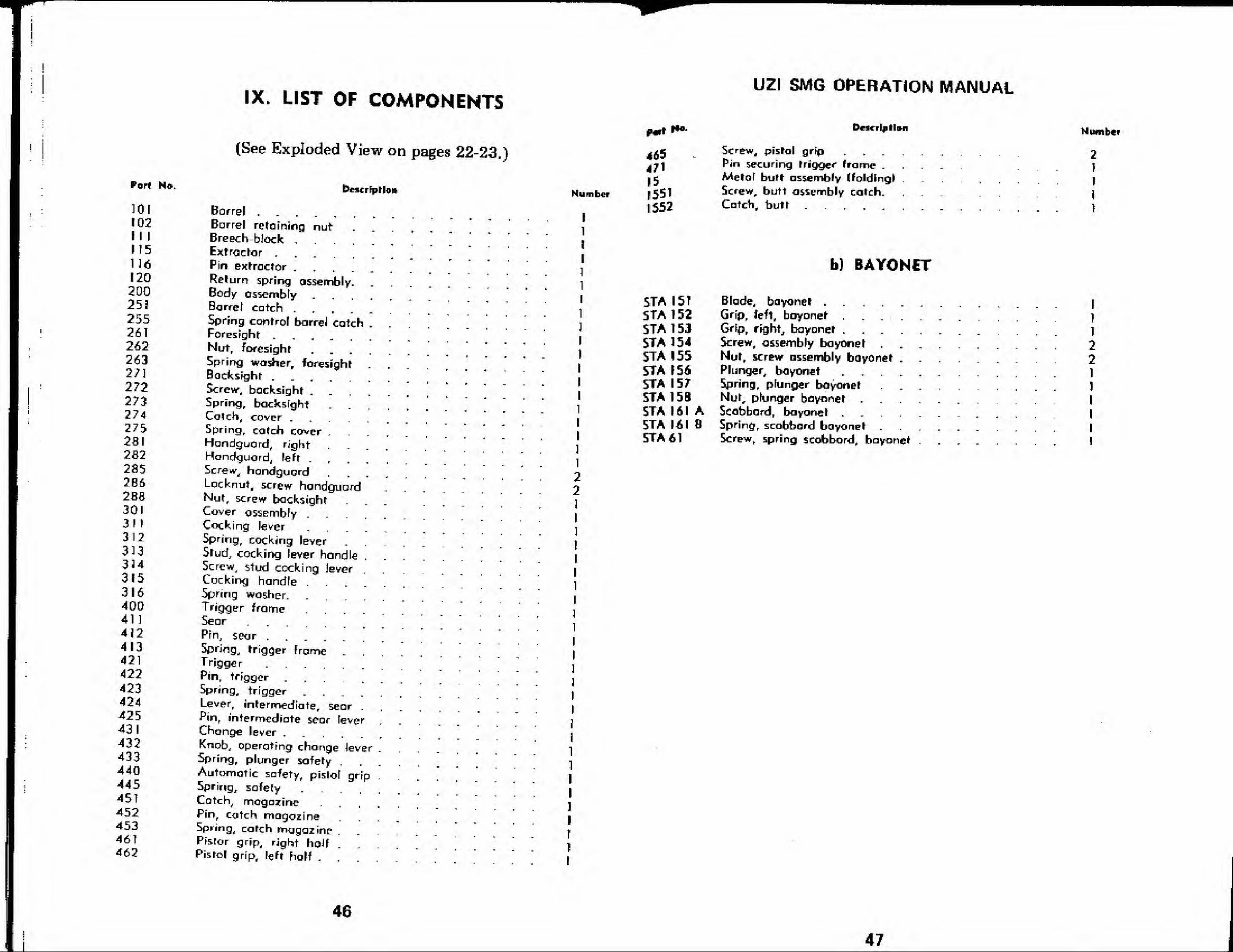
IX. LIST OF COMPONENTS
Port N*.
301102
II I
ITS11612020025325526T26226327]
2722732742752812S22852B62B83013113123133343153164004114J2413421422423424425431432433440445451452453461462
(See Exploded View on pages 22-23.)
Description
Barrel
Barrel retaining nutBreech-block
Extractor
Pin extractor
Return spring assembly. . .
Body assemblyBarrel catchSpring control barreJ catch .
Foresight
Nut, foresight
Spring washer, foresight . .
Backsight
Screvr, backsightSpring, backsight ....Catch, coverSpring, catch cover . , , ,
Hundcjuord, right ....Hondguord, left
Screw, hondguordLocknut, screw hondguardNut, screw backsightCover assemblyCocking lever
5pring, cocking leverStud, cocking lever handle
.
Screw, stud cocking jeverCocking handleSpring washer. .....Trigger frame .....SearPin, searSpring., trigger frame .
Trigger
Pin, trigger
Spring, triggerLever, intermediate, sear .
fin, intermediate sear feverChange lever
Knob, operating change lever .
5pring, plunger safety.
Automatic safety, pistol grip .
Spring, safety
Catch, magazinePin, catch magozineSpring, catch magazinePfeior grip, right half . . .
Pistol grip, left holf . . . .
Number
471
151551
1552
UZI SMG OPERATION MANUAL
Description
Screw4 pistol grip ....Pin securing trigger frame .
Meraf butt assembly (folding! .
Screw, butt assembly catch.
Catch, butt
tlumber
2
1
1
1
1
5TAI5TSTA 1 52STA 1 53
STA 1 54
STA 1 55STA 1 56STA 1 57STA 158STA 161 ASTA 161 8
STA 61
b) BAYONET
Blade, bayonetGrip, fefl, boyonetGrip, right, bayonet ....Screw, assembly bayonet . .
Nut, screw assembly bayonet .
Plunger, boyonet ....Spring, pfunger bayonetNut, pfunger bayonet .
Scabbard, bayonet ....Spring, scobbard bayonetScrew, spring scobbord, bayonet
I
1
1
2
21
1
I
I
I
!
46
47