MHS-3200A Dual-channel DDSSignalGenerator › SKU351386-MHS-3200A user-manual .pdf · MHS-3200A...
19
OPERATING MANUAL MHS-3200A Dual-channel DDS Signal Generator
Transcript of MHS-3200A Dual-channel DDSSignalGenerator › SKU351386-MHS-3200A user-manual .pdf · MHS-3200A...

OPERATING MANUAL
MHS-3200ADual-channel
DDS Signal Generator

1
Unpacking
When you get a new MHS-3200A Series dual-channel DDS signal generator, it
is recommended that you follow these steps to inspect the instrument.
1、Check for transportation damage caused.Such as packing or bubble bag cushions serious damage, keep them until the
machine and accessories passed the test.
2、Check the box in the article are complete.
The package contents as described below. If the content does not match or if the
instrument is damaged, contact your dealer or manufacturer.
Host computer:MHS-3200A Series dual-channel DDS signal generator 1
Accessory: Power Adapter 1
USB cable 1
Signal connection cable 2
User Manual (pdf version) 1
3. Check the machine
Inspect the instrument is damaged, not working properly, or fails performance tests,
please contact your dealer or the Company.

2
1 .Outline
1-1. The instrument Introduction
MHS-3200A series instruments using large scale integrated circuits and
high-speed FPGA MCU microprocessor, the internal circuit to take surface mount
technology has greatly enhanced the instrument's noise immunity and service life.
Display interface using LC1602 LCD display is divided into two lines, the top line
shows the current frequency, the following line displays additional parameters or
function variable and flexible use of flip key setting, greatly enhances the operability.
This instrument signal generation, waveform scanning, as well as the use of parameter
measurement has great advantages, is an electronic engineer, electronic laboratories,
production lines and teaching, research and the ideal test, measurement equipment.
Model Description
This series of instruments in four models, the main difference is the maximum
frequency sine wave, as follows:
MHS-3200-06M sinusoidal signals at frequencies up to 6MHz
MHS-3200-12M sinusoidal signals at frequencies up to 12MHz
MHS-3200-20M sinusoidal signals at frequencies up to 20MHz
MHS-3200-25M sinusoidal signals at frequencies up to 25MHz
The instrument characteristics1、Direct digital synthesis (DDS) technology, FPGA design, low power consumption;
2、Dual output, can work in sync phase adjustable;
3、It has up to 500 seconds of linear and logarithmic sweep function Sweep;
4、With a sine wave, triangle wave, square wave, sawtooth rise, falling sawtooth
waveform basic function and variable duty cycle pulse wave,
5、A total of 10 sets of parameters stored bits have M0 ~ M9, M0 boot automatically
transferred out of data;
6、At 12MHz or less, the sharpest of up to 15Vp-p, more than 12MHz, the biggest
reach 8Vp-p;
7、Built precision -20dB attenuator reach the minimum amplitude resolution 1mV;
3
8、With a 120% ~ + 120% DC bias function;
9、Pulse Duty precise adjustment to 0.1%;
10、Having four variable phase difference of TTL output;
11、Having a frequency measurement, period measurement, positive and negative
pulse width measurement, duty cycle measurements and counting function;
12、Four optional gate frequency measurement time, which strike a balance between
speed and accuracy;
13、All parametric equalizer can be done by an internal calibration procedure;
14、Powerful communications features, completely open communication protocol that
allows the secondary development of very simple;
15、This type machine can be equipped with an increase in power module, the signal
output amplitude reaches 30Vpp, the maximum output current reaches 1A;
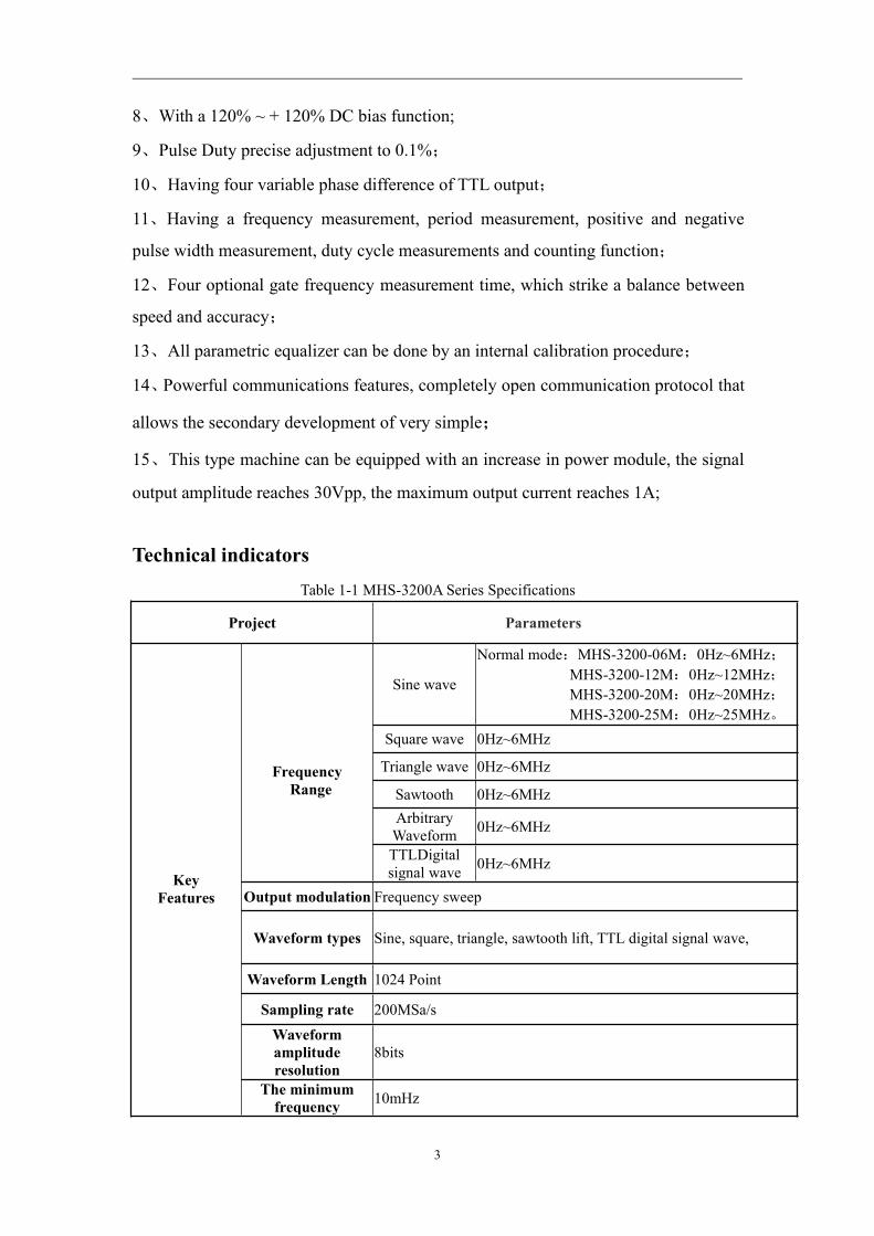
Technical indicatorsTable 1-1 MHS-3200A Series Specifications
Project Parameters
KeyFeatures
FrequencyRange
Sine wave
Normal mode:MHS-3200-06M:0Hz~6MHz;MHS-3200-12M:0Hz~12MHz;MHS-3200-20M:0Hz~20MHz;MHS-3200-25M:0Hz~25MHz。
Square wave 0Hz~6MHz
Triangle wave 0Hz~6MHz
Sawtooth 0Hz~6MHzArbitraryWaveform 0Hz~6MHz
TTLDigitalsignal wave 0Hz~6MHz
Output modulation Frequency sweep
Waveform types Sine, square, triangle, sawtooth lift, TTL digital signal wave,
Waveform Length 1024 Point
Sampling rate 200MSa/sWaveformamplituderesolution
8bits
The minimumfrequency 10mHz

4
resolution
Frequency error ±5×10⁻⁶
Frequency stability ±1×10⁻⁶
Amplitude range(peak to peak)
15mVp-p~15Vp-p(12MHz or less)15mVp-p~8Vp-p(12MHz above)
Output Impedance 50Ω±10%
Amplituderesolution
1mVp-p(-20dBAttenuation)10mVp-p(Does not decay)
Amplitude stability ±0.5%(Every five hours)
Amplitude error ± 1%+10mV(Frequency1KHz,15 Vp-p)
Offset Range -120%~+120%(The ratio of the bias voltage and signalamplitude)
Bias Resolution 1%
Phase range 0~359°
Phase resolution 1°
Sine waveHarmonic arrived
System 40dBc(<1MHz) ,35dBc(1MHz~20MHz)
Distortion <0.8%(20Hz~20KHz)
Square wave
Lifting along time ≤20ns
Overshoot ≤10%Duty cycle
adjustment range 0%~99.9%
TTL
Lifting along time ≤20ns
LOW <0.3V
High 1V~7.5V
Scan
Scan Mode Linear sweep, log sweep
Scan time 1S~500S
Scan range It is determined by the sweep parameter settings
Externalmeasurements
Frequency range
GATE-TIME=10S 0.1HZ - 60MHZGATE-TIME=1S 1HZ - 60MHZGATE-TIME=0.1S 10HZ - 60MHZGATE-TIME=0.01S 100HZ - 60MHZ
Input voltage range0.5Vp-p~20Vp-p
Counting range 0~4294967295
Counting Manually
Positive andnegative pulse
widthmeasurement
10ns resolution, the maximum measurable 10s

5
Periodicmeasurements 20ns resolution, the maximum measurable 20s
Duty CycleMeasurement 0.1% resolution, measuring range from 0.1% to 99.9%
Source Selection 1.Ext.IN input (AC signal), 2.TTL_IN input (digital signal)
MemoryMemory 10
Location M0-M9
Interface
Interface Using USB to serial interfacesCommunication
rate 57600bps
Protocol Using the command line, the agreement public
Power supply DC DC 5V
Size Length × width ×height 180×190×71mm
Weight Single 546g

6
Instrument Description
1、Panel
MHS-3200A Appearance Figure 2-1 shows the description of the parts as shown inTable 2-1.Figure 2-1 MHS3200A panel
Table 2-1 MHS3200A PanelGrade Explanation Grade Explanation
1 LCD1602 7 CH2 output interface
2 Status Indicator 8 DV5V power input
3 Operation buttons 9 USBcommunicationinterface
7
4 Knob10 TTL input / output
interfaceinterface5 Ext.In input interface
6 CH1 output interface 11 Switch
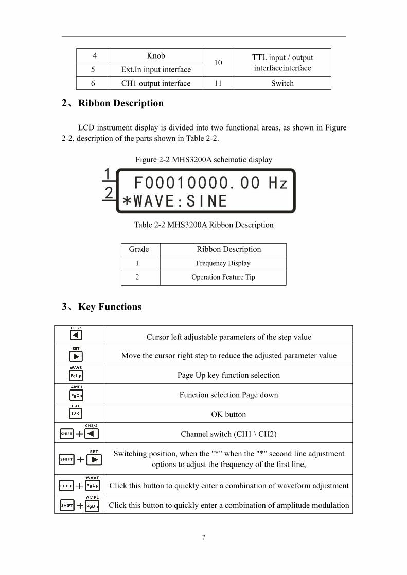
2、Ribbon Description
LCD instrument display is divided into two functional areas, as shown in Figure2-2, description of the parts shown in Table 2-2.
Figure 2-2 MHS3200A schematic display
Table 2-2 MHS3200A Ribbon Description
3、Key Functions
Cursor left adjustable parameters of the step value
Move the cursor right step to reduce the adjusted parameter value
Page Up key function selection
Function selection Page down
OK button
Channel switch (CH1 \ CH2)
Switching position, when the "*" when the "*" second line adjustmentoptions to adjust the frequency of the first line,
Click this button to quickly enter a combination of waveform adjustmentpage
Click this button to quickly enter a combination of amplitude modulationpage
Grade Ribbon Description
1 Frequency Display
2 Operation Feature Tip
8
Click this button to turn on or off output combination
InstructionsPower
1、Access 5V supply. You can use the box to configure oriented instrument powered
DC5V power adapter.
2、Enter the main interface.
Instructions
This section will detail how to operate the instrument. It should be noted that,
similar to the instrument channel CH1 CH2 channel with which the operating
instructions section 1-6 also apply to CH2 channel.
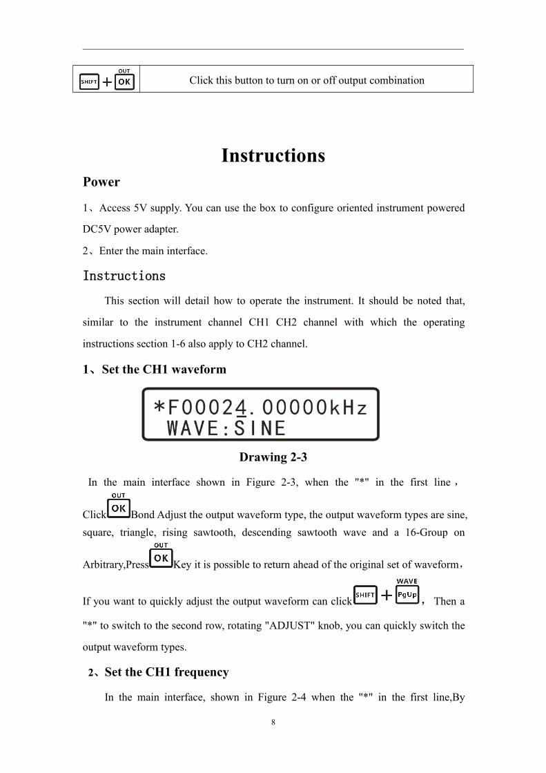
1、Set the CH1 waveform
Drawing 2-3
In the main interface shown in Figure 2-3, when the "*" in the first line ,
Click Bond Adjust the output waveform type, the output waveform types are sine,square, triangle, rising sawtooth, descending sawtooth wave and a 16-Group on
Arbitrary,Press Key it is possible to return ahead of the original set of waveform,
If you want to quickly adjust the output waveform can click ,Then a
"*" to switch to the second row, rotating "ADJUST" knob, you can quickly switch the
output waveform types.
2、Set the CH1 frequency
In the main interface, shown in Figure 2-4 when the "*" in the first line,By

9
adjusting or Move the cursor to adjust the frequency step size,Then to adjust
the frequency of the output waveform by rotating the "ADJUST" knob.
图 2-4
3、Setting the amplitude of CH1
In the main interface,Press Button after,The magnitude of the
interface will appear in a cursor set,Click or Button, It is possible to move the
cursor position, rotate "ADJUST" knob to adjust the amplitude of the output
waveform, as shown below:
Drawing 2-5
Wherein, 05.00V refers peak to peak. In this range setting function mode, the
maximum amplitude of 15V, minimum 0.15V, the minimum step value 0.01 (10mV);
as shown in a state 2-6,Press -20dB Attenuation state of the incoming signal, the
output signal of a maximum of 1.500V, the minimum value of 0.015V, the minimum
step is 0.001V (1mV).
图 2-6
4、Setting bias of CH1

10
In the main interface,Press 或 ,Adjusted to offset adjustment options
shown in Figure 2-7,Then click ,The "*" are switched to the second
row,Click or To move the cursor,Then"ADJUST" knob to adjust the offset
parameter.
Drawing 2-7
5、Duty cycle setting CH1
In the main interface,Press or ,Adjusted to duty cycle adjustment options
shown in Figure 2-8,Then click ,The "*" are switched to the second
row, click or To move the cursor,Then"ADJUST" knob to adjust the offset
parameter.
Drawing2-8
5、Setting the phase difference between the two channels
In the main interface,Press or ,Adjusting the phase adjustment options shown
in Figure 2-9, Then click ,The "*" are switched to the second row,
Click or To move the cursor, Then"ADJUST" knob to adjust the bias
parameter, you need special note is the phase difference only in the same frequency
CH1 and CH2 frequency when it makes sense.

11
Drawing 2-9
6、Setting the display unit of frequency
In the main interface,Press or ,Adjusted to the frequency display unit
adjustment options shown in Figure 2-9, Then click , The "*" are
switched to the second row,Then click Switching frequency units Hz、kHz、MHz。
图 2-10
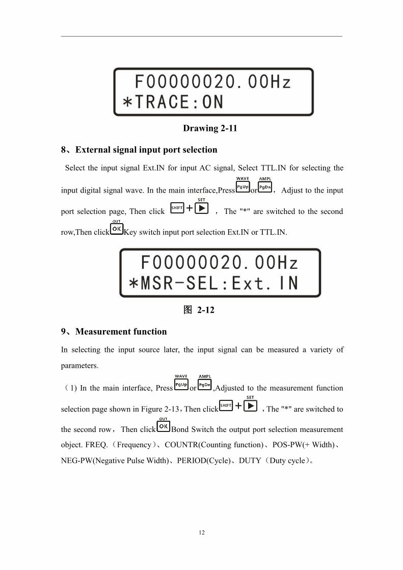
7、Tracking
Tracking function is used to synchronize the frequency of CH2 to CH1, and
users can set the amplitude of the tracking and duty track, In the main interface,
Press or , Adjusted to tracking options shown in Figure 2-11, Then
click , The "*" are switched to the second row, and then
click Switched ON or OFF state. When the tracking function is turned frequency
automatic tracking frequency channel CH2 CH1 channel. Also, before turning if
tracing, CH1 and CH2 channel amplitude is the same tracking feature is turned on
CH1 and CH2 frequency automatic tracking; if the duty is the same as CH1 and CH2
are turned on after tracing CH1 and CH2 account empty than automatic tracking.
12
Drawing 2-11
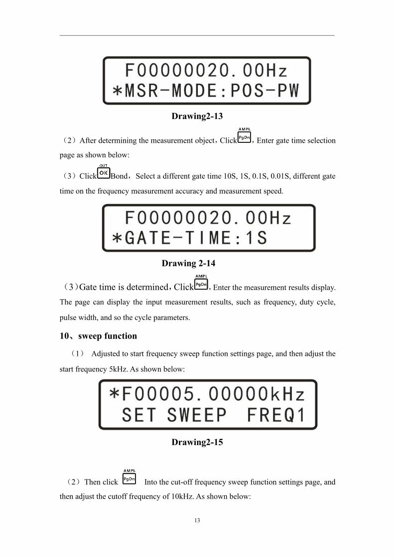
8、External signal input port selection
Select the input signal Ext.IN for input AC signal, Select TTL.IN for selecting the
input digital signal wave. In the main interface,Press or ,Adjust to the input
port selection page, Then click ,The "*" are switched to the second
row,Then click Key switch input port selection Ext.IN or TTL.IN.
图 2-12
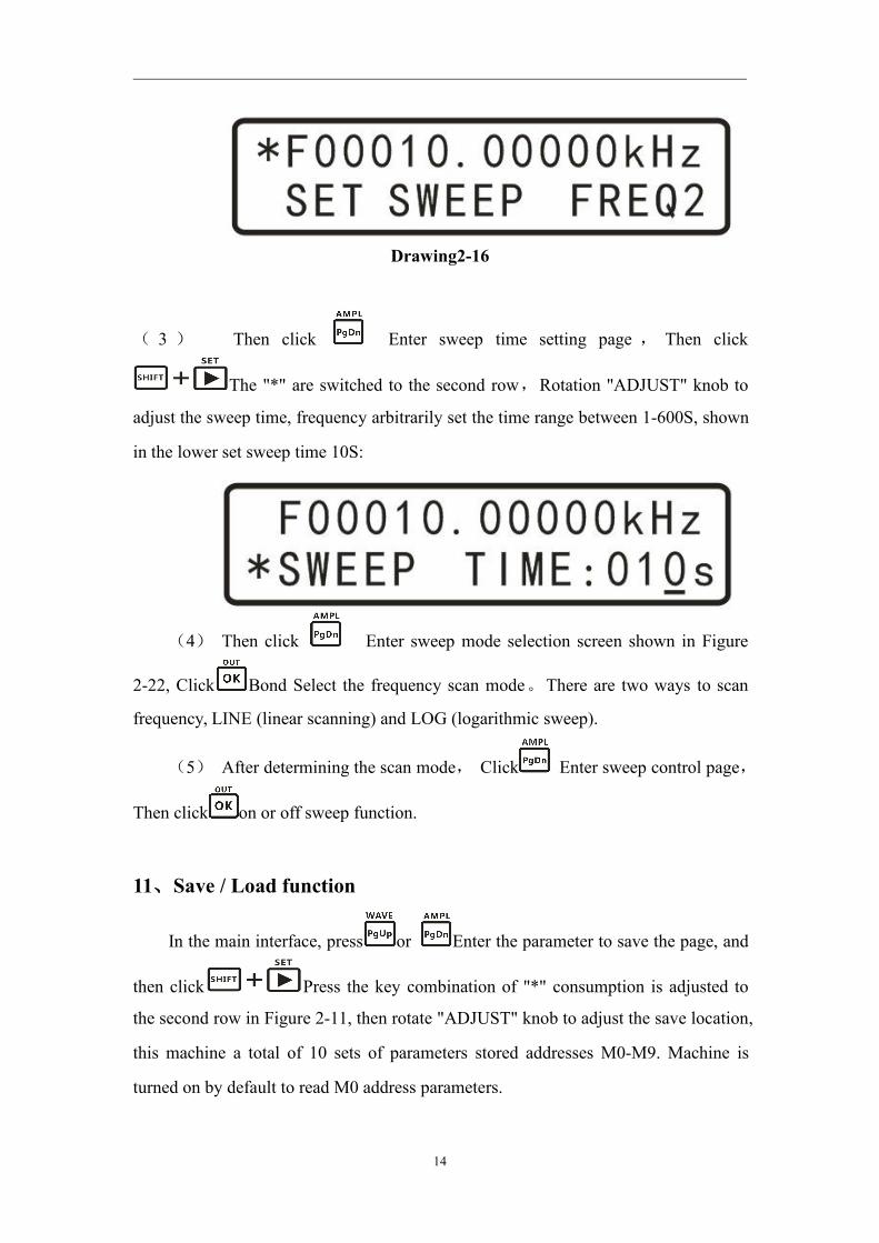
9、Measurement function
In selecting the input source later, the input signal can be measured a variety of
parameters.
(1) In the main interface, Press or ,Adjusted to the measurement function
selection page shown in Figure 2-13,Then click ,The "*" are switched to
the second row,Then click Bond Switch the output port selection measurement
object. FREQ.(Frequency)、COUNTR(Counting function)、POS-PW(+ Width)、
NEG-PW(Negative Pulse Width)、PERIOD(Cycle)、DUTY(Duty cycle)。
13
Drawing2-13
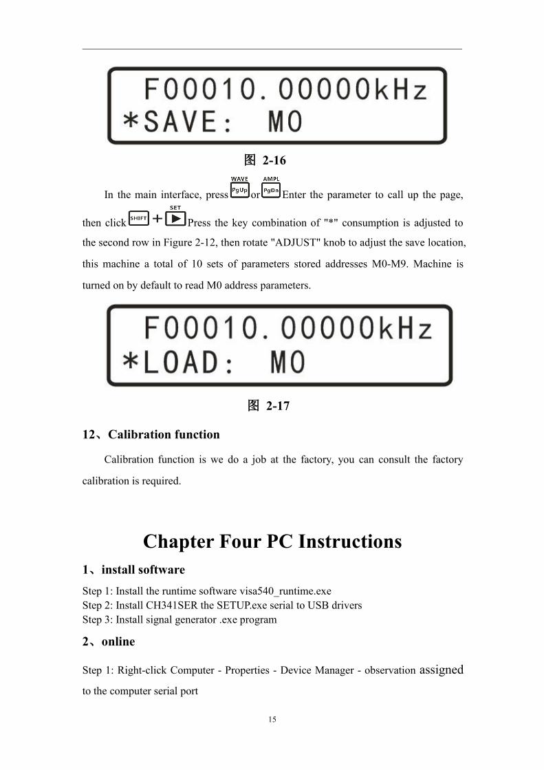
(2)After determining the measurement object,Click ,Enter gate time selection
page as shown below:
(3)Click Bond,Select a different gate time 10S, 1S, 0.1S, 0.01S, different gate
time on the frequency measurement accuracy and measurement speed.
Drawing 2-14
(3)Gate time is determined,Click ,Enter the measurement results display.
The page can display the input measurement results, such as frequency, duty cycle,
pulse width, and so the cycle parameters.
10、sweep function
(1) Adjusted to start frequency sweep function settings page, and then adjust the
start frequency 5kHz. As shown below:
Drawing2-15
(2)Then click Into the cut-off frequency sweep function settings page, and
then adjust the cutoff frequency of 10kHz. As shown below:
14
Drawing2-16
( 3 ) Then click Enter sweep time setting page , Then click
The "*" are switched to the second row,Rotation "ADJUST" knob to
adjust the sweep time, frequency arbitrarily set the time range between 1-600S, shown
in the lower set sweep time 10S:
(4) Then click Enter sweep mode selection screen shown in Figure
2-22, Click Bond Select the frequency scan mode。There are two ways to scan
frequency, LINE (linear scanning) and LOG (logarithmic sweep).
(5) After determining the scan mode, Click Enter sweep control page,
Then click on or off sweep function.
11、Save / Load function
In the main interface, press or Enter the parameter to save the page, and
then click Press the key combination of "*" consumption is adjusted to
the second row in Figure 2-11, then rotate "ADJUST" knob to adjust the save location,
this machine a total of 10 sets of parameters stored addresses M0-M9. Machine is
turned on by default to read M0 address parameters.
15
图 2-16
In the main interface, press or Enter the parameter to call up the page,
then click Press the key combination of "*" consumption is adjusted to
the second row in Figure 2-12, then rotate "ADJUST" knob to adjust the save location,
this machine a total of 10 sets of parameters stored addresses M0-M9. Machine is
turned on by default to read M0 address parameters.
图 2-17
12、Calibration function
Calibration function is we do a job at the factory, you can consult the factory
calibration is required.
Chapter Four PC Instructions1、install softwareStep 1: Install the runtime software visa540_runtime.exeStep 2: Install CH341SER the SETUP.exe serial to USB driversStep 3: Install signal generator .exe program
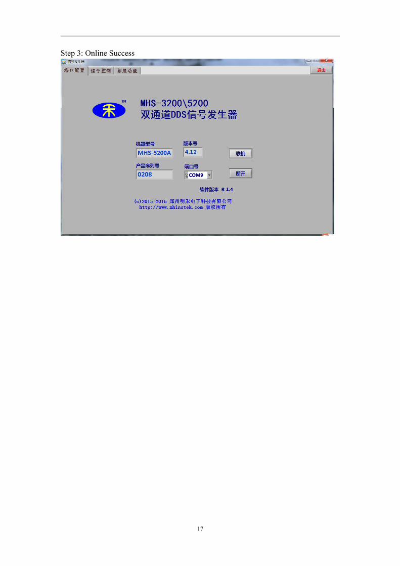
2、online
Step 1: Right-click Computer - Properties - Device Manager - observation assignedto the computer serial port

16
Step 2: Select the appropriate serial line after the point
17
Step 3: Online Success
18
Care and maintenance
1. Make sure the input power adapter correctly, the machine uses DC5V power
adapter;
2, the instrument display on the LCD module is fragile, perishable items, please do
not slam and near chemicals to prevent corrosion. When you feel the liquid surface
dust and dirt, wipe with a soft cloth carefully.
3, the working temperature of -10 ~ 50 ℃, Storage temperature -20 ~ 70 ℃, and the
instrument in a dry environment.
4. Do not attempt to disassemble the equipment, destroy the package will void the
warranty. The instrument is there are no user-serviceable parts, repairs may only
repair outlets or by specifying the return factory.
5, avoid lighted candles, a water cup, corrosive chemicals and other unsafe items
placed on the surface of the instrument, so as not to cause damage to the instrument.
6, the display screen are easy to pollution, fragile device, do not touch the hand as
well as external and collision, avoid children play this instrument.
7. Do not move the instrument to avoid severe irreparable damage to the internal
circuit when the instrument is working properly.
Exclude the above problem re-power the instrument still does not work, please
contact your supplier!