MH-Sensor 551405 RevB DE EN in progress new 20141211 Temposonics® Connector System meets the...
20
– Stroke range up to 5000 mm – Linearity < 0.04 % F.S. – Resolution typ. 0.5 mm The Measurable Difference DATA SHEET MH-Series MH200 Temposonics ® Magnetostrictive Linear Position Sensors
Transcript of MH-Sensor 551405 RevB DE EN in progress new 20141211 Temposonics® Connector System meets the...

– Stroke range up to 5000 mm
– Linearity < 0.04 % F.S.
– Resolution typ. 0.5 mm
The Measurable Difference
DATA SHEETMH-Series MH200
Temposonics®
Magnetostrictive Linear Position Sensors

I 2 I
Data SheetMH-Series MH 200
1. Product description and technology
Temposonics® sensors can be used in versatile mobile machines without any restriction and replace contact-based linear sensors like potentio-meters. Highly dynamic systems are controlled safely by means of Temposonics® sensors, thus enhancing the productivity, availability and quality of the working process of the machine. Insensitive to vibration, shocks, dust and weathering influence and electro-magnetic disturbances. Temposonics® MH Series sensors are successfully used in front axle and articulated frame steering cylinders, hydraulic jacks and in steering systems for hydraulic units on agricultural and construction machinery.
MagnetostrictionTemposonics® linear sensors are based on the magnetostrictive tech-nology. By measuring the actual position with a non-contact position magnet the sensor operates 100% wear-free. The absolute operating principle enables reliable readings without any reference point or recalibration. A mechanical strain pulse is triggered by the travelling position magnet. The runtime of this ultrasonic wave is measured precisely and compiled into standard electronic output signals.
- Due to small dimensions MH sensors require only little space- Suitable for operating pressures up to 300 bar - Unaffected by surrounding media such as ageing or foaming oil- Insensitive to shock and vibration- Designed for all current supply voltages (12/24 VDC)- Temposonics® sensors offer all common used output signals:
• Analog: VDC / mA• Bus protocols: CANopen, SAE J1939
Temposonics® Connector system (IP69K) Flange housing Position magnet Pressure pipe
1
2 3 4
Simple MechanicsThe extremely robust sensor consists of the following main parts:
The innovative connector system which is easy to install in a few seconds, any soldering or crimping needless, dust-and waterproof up to IP69K.The flange housing with built-in electronics and signal converter.The position magnet as only moving part, which is assembled into the piston bottom. This permanent magnet travels wear-free and contactless along the pressure pipe and measures the actual position.The pressure pipe placed within the drilled piston rod contains the protected magnetostrictive sensing element.
1
2
3
4
Measurement principle
Magnetic field strain pulse
Mechanichal strain pulse
Strain pulse detector
Moveable position magnet
magnetostrictive sensing element (waveguide)
Magnetic field position magnet
Current interrogation pulse

I 3 I
Data SheetMH-Series MH 200
2. Temposonics® connector system M12
MTS presents the innovative connector system for Temposonics® MH-SeriesThe Temposonics® Connector System meets the highest protection requirements important for a harsh environment in mobile hydraulic applications. Protection type IP69K performs water and dust proof. In addition it is even resistive against high pressure water cleaning.
The MH sensor is delivered by MTS together with the new connector system:The connector insert carrier is already connected to the sensor conductors, i.e. no soldering, any colour or connection mistake.
The connector insert is taken out of the cylinder through a borehole. The flange can easily be clicked in position from outside.
Four standard screws must be tightened to mount the connector system on the cylinder. In case of using angled type connectorsthe connector insert can be rotated inside the flange in 45˚ steps.
With a corresponding mating plug the connector system fulfills an IP rating of IP69K.
- Absolutely easy and safe installation.- No brazing or crimping of connecting leads is required.
1 2
3 4
Current interrogation pulse

I 4 I
Data SheetMH-Series MH 200
3. Dimensions
All d
imen
sion
s in
mm
Plea
se s
ee d
etai
led
mod
el c
onfig
urat
ion
on p
age
13 a
nd 1
5.
N (n
ull s
troke
)F.
S. (f
ull s
troke
)s
Z
30w
21.2
+0
Ø 48 f7
Ø 30
23.2 × 8.2
-0.2
d
11.5
±0.2
30
R2
M12×1
Ø 24+0-0.2
Pres
sure
pip
e Ø
10 m
mM
6 fe
mal
e (M
HL)
Hous
ing
e.g.
: s =
150
0 m
m
e.g.
: w =
120
mm
Mod
el n
o.
H FL
A01
C01
J01
4 3
MH
C1
MN
12
G3
V02
50
0
7F FD
Baud
rate
325
0 kb
it/se
c
412
5 kb
it/se
c
Node
ID7F
hex
FDhe
x
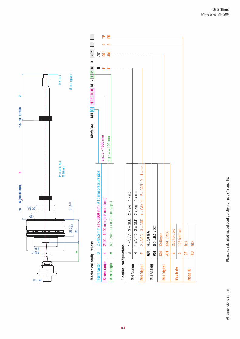
Elec
trica
l con
figur
atio
ns
MH
Anal
ogG
1 =
VDC
3 =
GND
2 =
Sig
4 =
n.c.
H1
= VD
C 3
= GN
D 2
= Si
g 4
= n.
c.
MH
Digi
tal
F2
= VD
C 3
= GN
D 4
= CA
N HI
5
= C
AN L
O 1
= n.
c.
MH
Anal
ogA0
14…
20 m
A
V02
0.5…
9.5
VDC
MH
Digi
tal
C01
CANo
pen
J01
SAE
J193
9
Mec
hani
cal c
onfig
urat
ions
Form
fact
orC
Z =
63.5
mm
(s <
500
0 m
m) ,
Ø 1
0 m
m p
ress
ure
pipe
LZ
= 69
.5 m
m (s
< 5
000
mm
), Ø
10 m
m p
ress
ure
pipe
Stro
ke ra
nge
s25
20…
5000
mm
(in
5 m
m s
teps
)
Wire
leng
thw
60…
240
mm
(in
20 m
m s
teps
)
I 5 I
Data SheetMH-Series MH 200
All d
imen
sion
s in
mm
N (n
ull s
troke
)F.
S. (f
ull s
troke
)s
30Z
30w
Ø30
11.5
±0.2
21.2
+0 -0.2
24+0 Ø-0.2
R2
Ø48 f7
M12×1Pr
essu
re p
ipe
Ø 10
mm
M8
mal
e
5 m
m s
quar
e
e.g.
: s =
150
0 m
m
e.g.
: w =
120
mmM
odel
no.
H F F
A01
C01
J01
4 3
MH
Q1
MN
12
G3
V02
50
0
7F FD
Mec
hani
cal c
onfig
urat
ions
Form
fact
orQ
Z =
85.5
mm
(s <
500
0 m
m) Ø
10
mm
pre
ssur
e pi
pe
Stro
ke ra
nge
s25
20…
5000
mm
(in
5 m
m s
teps
)
Wire
leng
thw
60…
240
mm
(in
20 m
m s
teps
)
Baud
rate
325
0 kb
it/se
c
412
5 kb
it/se
c
Node
ID7F
hex
FDhe
x
Elec
trica
l con
figur
atio
ns
MH
Anal
ogG
1 =
VDC
3 =
GND
2 =
Sig
4 =
n.c.
H1
= VD
C 3
= GN
D 2
= Si
g 4
= n.
c.
MH
Digi
tal
F2
= VD
C 3
= GN
D 4
= CA
N HI
5
= C
AN L
O 1
= n.
c.
MH
Anal
ogA0
14…
20 m
A
V02
0.5…
9.5
VDC
MH
Digi
tal
C01
CANo
pen
J01
SAE
J193
9
Plea
se s
ee d
etai
led
mod
el c
onfig
urat
ion
on p
age
13 a
nd 1
5.

I 6 I
Data SheetMH-Series MH 200
Sensor installationThe method of installation is entirely dependent on the cylinder design. While the most common method of installation is from the rod side of the cylinder, an installation from the head side of the cylinder is also possible. In both installation methods, the hermetic sealing of the cylinder is given by an O-ring with additional back up ring.
4. In Cylinder assembly
Mechanical installation The robust Temposonics® model MH sensor is designed for direct stroke measurement in hydraulic cylinders. The Temposonics® MH sensor can be installed from the head side or the rod side of the cylinder depending on the cylinder design.
Flange housing with O-ring and back-up ring
All dimensions in mm
Please pay attention to installation manual! TypeB
Ø Cylinder D
Ø min. H
Depth d
Ø min. h
Depth
MH 52 48 21.2 > 32.5 < 40
> 15
Example:e.g. retaining with set screw DIN 913 M5 × 10 (with fl at point!)max. torque 0.5 Nm
Please pay attention:• The position magnet shall not touch the pressure pipe.• Do not exceed operating pressure.• Piston rod drilling: Depth: S + Z + 3 mm Diameter: Ø 13 mm minimum
Example
45°
4.54
1
4.5
8.5
D d
H h
B
30
>15 21.2-0.2
Hydraulic oil
Oil inlet PistonS Z ≥ 3

I 7 I
Data SheetMH-Series MH 200
4.1 Position magnets
Position magnets (please order separately) for installation without support tube
Ø 13.5
Ø 17.4
7.9
Ø 25.4
Ø 13.5 7.9
Ø 32.8
Ø 23.8Ø 13.5
Ø 4.3
7.9
Name Ring magnet OD17.4 Ring magnet OD25.4 Ring magnet OD33
Part no. 401 032 400 533 201 542-2
Dimensions
ODM 17.4 mm 25.4 mm 32.8 mm
IDM 13.5 mm 13.5 mm 13.5 mm
Height 7.9 mm 7.9 mm 7.9 mm
PA* 10 N/mm2 40 N/mm2 40 N/mm2
Characteristics
Material PA neobond PA ferrite PA ferrite
Weight ca. 5 g ca. 10 g ca. 14 g
Operating temperature −40…+100 °C −40…+100 °C −40…+100 °C
Surface pressure max. 20 N/mm2 max. 40 N/mm2 max. 40 N/mm2
Fastening torque for M4 screws
- - max. 1 Nm
*max. mechanical burden, e.g. by circlip, lock washers etc.
Position magnets (please order separately) for installation with support tube
Ø 19.8
Ø 30.5
7.6Ø 26
Ø 32
12
Name Ring magnet Ring magnet
Part no. 402 316 403 974
Dimensions
ODM 30.5 mm 32.0 mm
IDM 20.0 mm 26.0 mm
Height 8.0 mm 12.0 mm
PA* 40 N/mm2 40 N/mm2
Support tube
18 × 1.5 mm 22 × 2 mm
Characteristics
Material PA ferrite coated NdFeB
Weight ca. 13 g ca. 70 g
Operating temperature −40…+100 °C −40…+100 °C
Surface pressure 20 N/mm2 20 N/mm2
I 8 I
Data SheetMH-Series MH 200
SC
Ø 13 mmOD
dSM
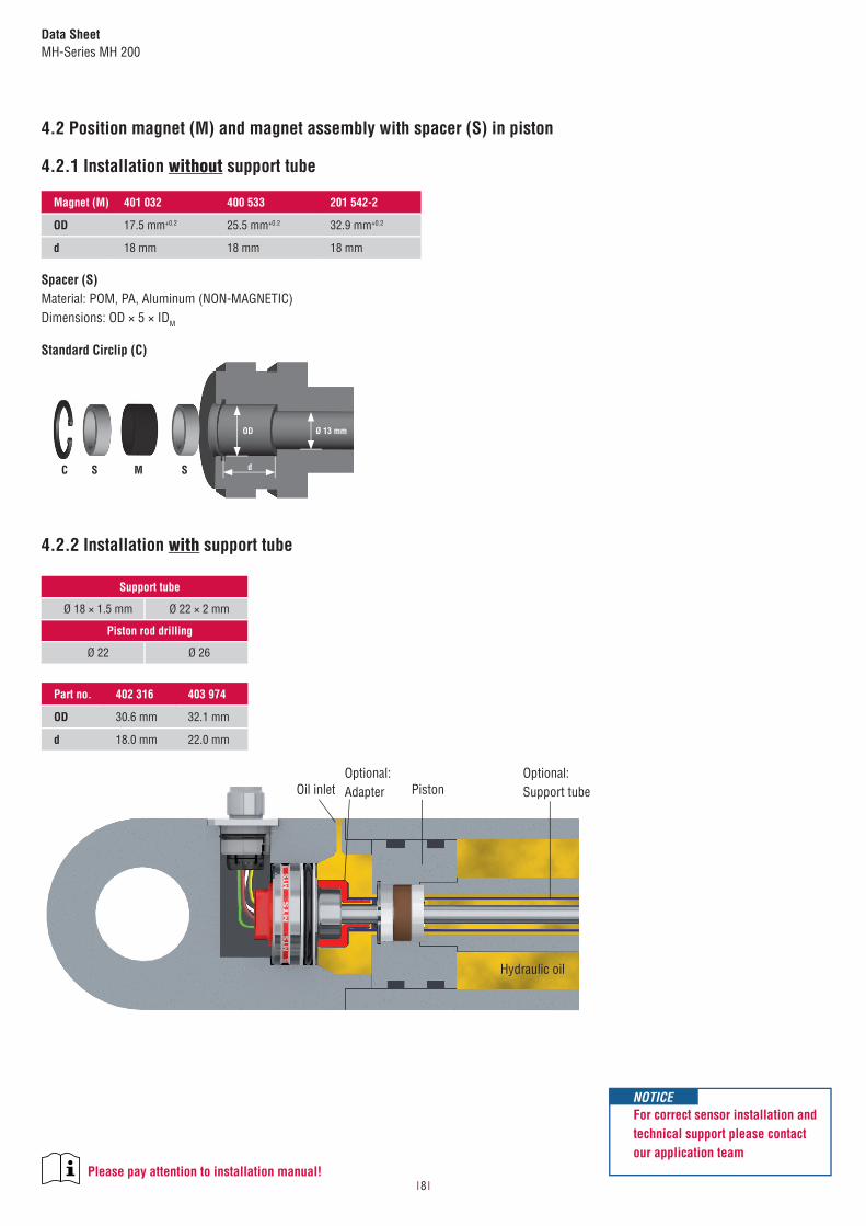
Magnet (M) 401 032 400 533 201 542-2
OD 17.5 mm+0.2 25.5 mm+0.2 32.9 mm+0.2
d 18 mm 18 mm 18 mm
Please pay attention to installation manual!
Optional: Adapter PistonOil inlet
Hydraulic oil
Optional: Support tube
4.2 Position magnet (M) and magnet assembly with spacer (S) in piston
4.2.1 Installation without support tube
Support tube
Ø 18 × 1.5 mm Ø 22 × 2 mm
Piston rod drilling
Ø 22 Ø 26
Part no. 402 316 403 974
OD 30.6 mm 32.1 mm
d 18.0 mm 22.0 mm
4.2.2 Installation with support tube
For correct sensor installation and technical support please contact our application team
NOTICE
Spacer (S)Material: POM, PA, Aluminum (NON-MAGNETIC)Dimensions: OD × 5 × IDM
Standard Circlip (C)

I 9 I
Data SheetMH-Series MH 200
4.3 Support tube assembly for MH model MHQ
Please pay attention to:• Support tube adapters must enable oilflow to get rid of air when cylinder gets oil filled• Support tubes material is stainless steel 1.4301 (AISI 304) or 1.4305 (AISI 303).
If machining is conducted on stainless steel support tubes please make sure it does not induce magnetic properties to the material.• Nut M8 to tighten with max. 4 Nm. Use glue to fix the nut• Use a wrench 5 mm to hold the pressure pipe end when tighten the nut M8• No torsional stress to apply on the pressure pipe• Adapters material: stainless steel, aluminum, PA or POM• Head and tail adapter: OD tolerances are applied in conjunction with the tolerances valid for the wall thickness of selected support tube
4.3.3 Assembly adapters
All dimensions in mm
Head Tail (for 18 × 1.5 mm support tube) Tail (for 22 × 2 mm support tube)
Adapters, support tube, locknuts, etc. are not part of MTS shipment.
Ø10,
5+0,1
2,5×45°
Ø24,
2 ±
10 1×45°
0,2
0,1
R2
Ø10,
2+0,1
R20
10 25
Ø10,
2+0,1
R30
10 25
4.3.1 Support tube assembly
lock nut
tailsupport tube
head
2
For correct sensor installation and technical support please contact our application team
NOTICE
Please note that the support tube assembly and the adapter accessories is a proposal by MTS.For further design information please consult MTS application engineering who will consult and clarify as required.

I 10 I
Data SheetMH-Series MH 200
4.4 Operating conditions and load limits considering a sensor installation with support tube.
4.4.1 Vibration Ratings on MachinesVibration ratings for machines are shown in the EU directive 2002/44/EC.Real effective accelerations and forces within the hydraulic cylinder may exceed this level.
For the cylinder installation requiring a support tube an applied load collective has been defined in order to approve the design for the resonance frequency range.
Considering the results out of the load collective the operating grade for pressure and vibration loads has been conducted. The calculation follows the guideline published from Mechanical Engineering Research Community FKM Germany.
1000
100
10
191 92 93 94 95
Frequency (Hz)96 97 98 99 100
Acce
lera
tion
(g)
For pressurized hydraulic cylinders the operating grade is given wide below 100%.
Diagramm (operating grade in %)100 % = Burst Level 50 % = 5.3 g Peak Acceleration 25 % = 1.5 g Effective Load Cycle, 2.15 g Peak Acceleration 0 % = without Load
4.4.2 Load Cycle Test with Support Tube 22×2mmReference Cylinder- horizontal Installation.Resonance Endurance Test 2.5×10⁶ Load Cycles with Sinus Wave Form.To perform and approve the mechanical load within the resonance range (94 Hz to 95 Hz). The test was passed without any permanent damages observed after this test.
Resonance Endurance Test
100 %
50 %
25 %
0 %
Boom Extension

I 11 I
Data SheetMH-Series MH 200
5. Electrical installation
Please pay attention to installation manual!
MH AnalogPIN assignment M12 4 pin
1
4 3
2
Pin G H
1 VDC VDC
2 n.c. Signal
3 GND GND
4 Signal n.c.
Pin assignment “G” Pin assignment “H”
(1) +12 / 24 VDC(2) n.c.(3) GND (O V)(4) Signal: mA, VDC
0 VDC
(1) +12 / 24 VDC(2) Signal: mA, VDC(3) GND (O V)(4) n.c.
0 VDC
MH DigitalPIN assignment M12 5 pin
1
4 3
5
2
Pin F
1 n.c.
2 VDC
3 GND
4 CAN HI
5 CAN LO
Pin assignment “F”
(1) n.c.(2) +12/24 VDC(3) GND (O V)(4) CAN HI(5) CAN LO 120 Ω
Bus termination external
MH Analog wire assignment
Color Signal
BN VDC
WH GND
GN Signal
M12 connector system
102
9
16H8
40
M12
x 1
21
14 3
2
17
24
Ø 4,4
10
2
9
16H8
M12 × 1
21
Chassis GND
VDCGNDSignal
+12/24 VDC
1 2
34 BAT
GEN
+ -
M
All dimensions in mm
cable shield (optional)

I 12 I
Data SheetMH-Series MH 200
InputMeasured value positionStroke range 2520…5000 mm (in 20 mm steps)OutputSignal characteristic analog output restricted by noise or A/D converter of control unitVoltage 0.5…9.5 VDC Current 4…20 mAResolution 2520…3500 mm ≤ 0.5 mm 3520…5000 mm ≤ 1.0 mmPower up time typ. 250 msMounting zone 30 mm
Damping63.5 mm69.5 mm (M6 female) / 85.5 mm (M8 male)
Accuracy
Linearity2520…3500 mm ≤ ±1.0 mm 3520…5000 mm ≤ ±2.0 mm
Hysteresis2520…3500 mm ≤ ±0.5 mm 3520…5000 mm ≤ ±1.0 mm
Internal sample rate 2 msSetpoint tolerance ≤1 mmOperating conditionsMounting position anyOperating temperature electronics −40…+105 °CStorage temperature −25…+ 65 °CFluid temperature −30…+ 85 °CDew point, humidity EN60068-2-30, 90 % rel. humidity, no condensationPressure without considering support tube assemblyOperating pressure ratings pressure impulse test according DIN EN ISO 19879 (Ø 10 mm pressure pipe)PN 320 barPmax 400 barPstatic 550 barIP ratingM12 connector EN60529 (IP69K) when pluggedSensor housing EN60529 (IP67)Environmental testingShock test IEC 60068-2-27, 50 g (11 ms) single shock, 15 g (11 ms) at 1000 shocks per axisVibration test IEC 60068-2-64, 5 g (r.m.s.) Ø 10 mm pressure pipe (10…2000 Hz) - resonance frequencies excludedEMC test ISO 14982 Agricultural and forest machines
Immunity: ISO 11452-2 (200 V/m Antenna), ISO 11452-4 (200 mA BCI)Emissions: CISPR 25Transiente Impulses: ISO 7637-1/2E.S.D.: ISO/TR 10605
Materials and dimensionsPressure pipe (Ø 10 mm) stainless steel 1.4306 / AISI 304LHousing stainless steel 1.4305 / AISI 303Sealing O-ring 40.87 × 3.53 mm NBR 80, back-up ring 42.6 × 48 × 1.4 PTFESupport tube stainless steel 1.4301 / AISI 304Support tube adapter (head/tail) stainless steel 1.4305 / AISI 303M12 connector insert material: polyamide reinforces; O-ring 7 × 1.35 mm NBR 70; pins: brass with gold plated pinsM12 flange brass nickel-plated with O-ring 13 × 1.6 NBR 70Electrical installationConnector M12 male plugSupply voltage 12 VDC (tolerance range 8…32 VDC) 24 VDC (tolerance range 8…32 VDC)Current consumption typ. < 100 mA typ. < 50 mALoad (output VDC) RL > 10 kΩ RL > 10 kΩLoad current (output VDC) typ. 1 mA typ. 1 mALoud (output mA) RL < 250 Ω RL < 500 ΩInrush current max. 2.5 A / 2 ms max. 4.5 A / 2 ms Supply voltage ripple < 1 % p-pPower drain < 1 WOver voltage protection (GND-VDC) up to +36 VDCPolarity protection (GND-VDC) up to −36 VDCInsulation Resistance R ≥ 10 MΩ @ 60 secElectric strength 500 VDC (DC GND to chassis GND)
6. MH Analog: Technical data

I 13 I
Data SheetMH-Series MH 200
6.1 Model configurator
MH Testkit Part no.
Scope of delivery:• MH-Series analog / PWM Tester• 12 VDC battery charger with adapter (adapter main plug EU, adapter main plug UK)• cable with M12 connector• cable with pigtailed wires• carrying case• CD-ROM with user’s guide
280 618
Accessories (selection) Part no.
OD17.4 Ring magnet, standard installation 401 032
OD25.4 Ring magnet, support tube installation 400 533
OD32 Ring magnet, support tube installation 403 974
b Form factor
C Pressure pipe Ø 10 mm, Damping: 63.5 mm
L Pressure pipe Ø 10 mm, Damping: 69.5 mm, M6 female
Q Pressure pipe Ø 10 mm, Damping: 85.5 mm, M8 male port
c Stroke range (mm)
2520…5000 mm (in 20 mm steps)
a Sensor model
M H Flange housing Ø 48 mm
e Supply voltage
3 +12 / 24 VDC
f Output
V 0 2 0.5…9.5 VDC
A 0 1 4…20 mA
Scope of delivery:
Position sensor, O-ring, backup-ring, M12 connector system
Please order M12 flange and magnets separately!
MH Test-Kit
M H M 3
a b c d e f
d Electrical wiring
M12 connector Examples M12 connector
N G 4 pin (1-3-4), 60…240 mm wire length (in 20 mm steps) N08G = 080 mm
N H 4 pin (1-3-2), 60…240 mm wire length (in 20 mm steps) N10H = 100 mm
Pigtail Examples cable
T A 3 wires, 300…9000 mm wire length (in 100 mm steps) T10A = 1000 mm
Adapters, support tube, locknuts, etc. are not part of MTS shipment. Please consult MTS for engineering support

I 14 I
Data SheetMH-Series MH 200
InputMeasured value position and velocityStroke range 2520…5000 mm (in 20 mm steps)Velocity range 0…1000 mm/sOutputSignal characteristic Bus-protocol: SAE J1939, CANopen protocol according to CiA DS-301 V4.1, device profile DS-406 V3.1Resolution (position) 0.5 mm Resolution (velocity) 1 mm/sBoot up time typ. 400 ms
Cycle timeCANopen: 2 ms SAE J1939: 20 ms
Mounting zone 30 mm
Damping63.5 mm69.5 mm (M6 female) / 85.5 mm (M8 male)
Accuracy
Linearity2520…3500 mm ≤ ±1.0 mm 3520…5000 mm ≤ ±2.0 mm
Hysteresis ±0.5 mmInternal sample rate 2 msSetpoint tolerance ±0.2 mmOperating conditionsMounting position anyOperating temperature electronics −40…+105 °CStorage temperature −25…+ 65 °CFluid temperature −30…+ 85 °CDew point, humidity EN60068-2-30, 90 % rel. humidity, no condensationPressure without considering support tube assemblyOperating pressure ratings pressure impulse test according to DIN EN ISO 19879 (Ø 10 mm pressure pipe)PN 320 barPmax 400 barPstatic 550 barIP ratingM12 connector EN60529 (IP69K) when pluggedSensor housing EN60529 (IP67) Environmental testingShock test IEC 60068-2-27, 50 g (11 ms) single shock, 15 g (11 ms) at 1000 shocks per axisVibration test IEC 60068-2-64, 5 g (r.m.s.) Ø 10 mm pressure pipe (10…2000 Hz) - resonance frequencies excludedEMC test ISO 14982 Agricultural and forest machines
Immunity: ISO 11452-2 (200 V/m Antenna), ISO 11452-4 (200 mA BCI) Emissions: CISPR 25Transiente Impulses: ISO 7637-1/2E.S.D.: ISO/TR 10605
Materials and dimensionsPressure pipe stainless steel 1.4306 / AISI 304LHousing stainless steel 1.4305 / AISI 303Sealing O-ring: 40.87 × 3.53 mm NBR 80; back-up ring: 42.6 × 48 × 1.4 PTFESupport tube stainless steel 1.4301 / AISI 304Support tube adapter (head/tail) stainless steel 1.4305 / AISI 303M12 connector insert material: polyamide reinforces; O-ring 7 × 1.35 mm NBR 70; pins: brass with gold plated pinsM12 flange brass nickel-plated with O-ring 13 × 1.6 NBR 70Electrical installationConnector M12 male plugSupply voltage 12 VDC (8…32 VDC) 24 VDC (8…32 VDC)Current consumption typ. < 100 mA typ. < 50 mAInrush current max. 1.0 A @ 2 ms max. 1.5 A @ 2 msBus termination (HI-LO) 120 ΩSupply voltage ripple < 1 % p-pPower drain < 1.5 WOver voltage proctection (GND-VDC) up to +36 VDCPolarity protection (GND - VDC) up to −36 VDCInsulation Resistance R ≥ 10 MΩ @ 60 sec.Electric strength 500 VDC (DC GND to chassis GND)
7. MH Digital: Technical data

I 15 I
Data SheetMH-Series MH 200
7.1 Model configurator
b Form factor
C Pressure pipe Ø 10 mm, Damping: 63.5 mm
L Pressure pipe Ø 10 mm, Damping: 69.5 mm, M6 female
Q Pressure pipe Ø 10 mm, Damping: 85.5 mm, M8 male
c Stroke range (mm)
2520…5000 mm (in 20 mm steps)
a Sensor model
M H Flange housing Ø 48 mm
e Supply voltage
3 +12 / 24 VDC
f Output
C 0 1 CANopen cycle time 1 ms (default setting)
J 0 1 SAE J1939 cycle time 20 ms (default setting)
Scope of delivery:Position sensor, O-ring, backup-ring, M12 connector system
Please order M12 flange and magnets separately!
g Baud rate
CANopen (C01)
0 1000 kbit/sec
1 800 kbit/sec
2 500 kbit/sec
3 250 kbit/sec (default setting)
4 125 kbit/sec
6 50 kbit/sec
SAE J1939 (J01)
3 250 kBit
h Node-ID (CANopen) / Source adress (SAE J1939)
CANopen (C01)
hex 01…7F (default setting: 7F)
SAE J1939 (J01)
hex 01…FD (default setting: FD)
M H M 3
a b c d e f g h
d Electrical wiring
M12 connector
N F 5 pin (2-3-4-5), 60…240 mm wire length (in 20 mm steps)
Adapters, support tube, locknuts, etc. are not part of MTS shipment. Please consult MTS for engineering support

I 16 I
Data SheetMH-Series MH 200
MH Test-Software
Accessories Part no.
OD17.4 Ring magnet, standard installation 401 032
OD30.5 Ring magnet, support tube installation 402 316
OD32 Ring magnet, support tube installation 403 974
MH Testkit Part no.
Software 625 129
HardwareScope of delivery:• MH-Series CANopen / J1939 Test Software installation CD• USB CAN-modul kit: - USB CAN modul - USB CAN modul utility CD (with drives and description) - USB connector cable• Cable with MTS M12 connector and RS232 connector• Cable with core cable ends and RS232 connector• Carrying case• Installation manual on CD• 12 V charger with adapter
254 267
Accessories

I 17 I
Data SheetMH-Series MH 200
Notes

I 18 I
Data SheetMH-Series MH 200
Notes

I 19 I
Data SheetMH-Series MH 200
Notes

Document Part Number: 551405 Revision B (EN) 12/2014
MTS and Temposonics® are registered trademarks of MTS Systems Corporation. All other trademarks are the property of their respective owners. Printed in Germany. Copyright © 2014 MTS Sensor Technologie GmbH & Co. KG. Alterations reserved. All rights reserved in all media. No license of any intellectual property rights is granted. The information is subject to change without notice and replaces all data sheets previously supplied. The availability of components on the market is subject to considerable fluctuation and to accelerated technical progress. Therefore we reserve the right to alter certain components of our products depending on their availability. In the event that product approbations or other circumstances related to your application do not allow a change in components, a continuous supply with unaltered components must be agreed by specific contract.
LOCA
TION
S
LEGA
L NO
TICE
SGERMANYMTS Sensor TechnologieGmbH & Co. KGAuf dem Schüffel 958513 Lüdenscheid, GermanyTel. + 49 2351 9587-0Fax + 49 2351 [email protected]
USAMTS Systems CorporationSensors Division3001 Sheldon DriveCary, N.C. 27513, USATel. +1 919 677-0100Fax +1 919 [email protected]
JAPANMTS Sensors Technology Corp.737 Aihara-machi, Machida-shi, Tokyo 194-0211, JapanTel. + 81 42 775-3838Fax + 81 42 775- [email protected]
FRANCEMTS Systems SASZone EUROPARC Bâtiment EXA 16 16/18, rue Eugène Dupuis94046 Creteil, FranceTel. + 33 1 58 4390-28Fax + 33 1 58 [email protected]
ITALYMTS Systems Srl.Sensor Division Via Camillo Golgi, 5/725064 Gussago (BS), Italy Tel. + 39 030 988 3819Fax + 39 030 982 [email protected]
CHINAMTS Sensors Room 504, Huajing Commercial Center, No. 188, North Qinzhou Road 200233 Shanghai, ChinaTel. +86 21 6485 5800 Fax +86 21 6495 [email protected]
Reg.-No. 003095-QN