MGV Series - Akribis Sys...Specifications MGV MGV Series Akribis systems V-43 / V-44 MGV AVM30-15...
3
Specifications MGV MGV Series Akribis systems V-43 / V-44 MGV AVM30-15 AVM40-20 AVM90-30 AVM60-25 MGV 38 MGV 41 MGV 84 MGV 52 N N N/SqRt (W) W W V ℃ A A N/A V/m/s mH Ohms ms 4.6 29.4 2.26 4.2 169.6 48 155 0.63 4.00 7.35 7.35 2.94 10.6 0.3 9.9 58.1 3.89 6.5 222.8 60 155 0.77 4.50 12.90 12.90 6.22 11 0.6 26.4 119.0 7.45 12.5 254.8 60 155 1.55 7.00 17.00 17.00 6.42 5.2 1.2 74.3 315.0 13.21 31.6 568.4 60 155 3.30 14.00 22.50 22.50 6.61 2.9 2.3 kg kg kg mm μm μm μm μm μm N Nm Nm Nm N Nm Nm Nm ±3μm/25mm ±3μm/25mm ±1.5μm ±3μm/25mm ±0.5μm/25mm 0.084 0.366 0.3 15 0.162 0.715 0.8 20 0.391 1.703 2.0 25 1.386 5.457 6.0 30 129.0 5.0 3.1 3.7 2.9 1.7 1.0 1.2 231.0 10.6 7.8 9.0 7.8 3.5 2.6 3.0 706.0 23.1 12.0 12.0 19.6 7.7 4.0 4.0 1710.0 176.0 51.2 51.2 58.9 58.7 17.1 17.1 * Stroke refers to hardstop-to-hardstop. The limit sensors are positioned 0.5mm from the hardstops. Varied specifications Miniature linear guidance rails Suitable for high speed and acceleration applications Direct Drive Zero cogging and backlash ironless linear motor actuator Stroke from 15mm to 30mm Electrical Parameters Continuous Force, Coil @100 ºC Peak Force Motor Constant Continuous Power Peak Power Max Bus Voltage Max Coil Temperature Continuous current Peak Current, I peak Force Constant Back EMF Constant, V emf Inductance Terminal Resistance @ 25ºC Electrical Time Constant Mechanical Parameters Moving Mass Total Mass Recommended maximum load Stroke * Performance Parameters Straightness Flatness Bidirectional Repeatability Linearity without mapping Linearity with mapping Bearing Parameters Maximum static load capacity Maximum static roll moment Maximum static pitch moment Maximum static yaw moment Recommended maximum load 1 Recommended roll moment Recommended pitch moment Recommended yaw moment 1: The recommended maximum load is based on the load in which the acceleration of the moving mass is at least 1G. ISO 230-2:1997 – Bidirectional Repeatability, Bidirectional Accuracy, Bidirectional positional deviation Note: The straightness, bidirectional repeatability and linearity are qualified according to ISO 230-2:1997. Note: Please contact us for customized stroke. Unit Driven by Voice Coil Stages & Systems
Transcript of MGV Series - Akribis Sys...Specifications MGV MGV Series Akribis systems V-43 / V-44 MGV AVM30-15...

SpecificationsMGV
MGV Series
Akrib
is systems
V-43 / V-44
MGV
AVM30-15 AVM40-20 AVM90-30AVM60-25MGV 38 MGV 41 MGV 84MGV 52
N
N
N/SqRt (W)
W
W
V
℃
A
A
N/A
V/m/s
mH
Ohms
ms
4.6
29.4
2.26
4.2
169.6
48
155
0.63
4.00
7.35
7.35
2.94
10.6
0.3
9.9
58.1
3.89
6.5
222.8
60
155
0.77
4.50
12.90
12.90
6.22
11
0.6
26.4
119.0
7.45
12.5
254.8
60
155
1.55
7.00
17.00
17.00
6.42
5.2
1.2
74.3
315.0
13.21
31.6
568.4
60
155
3.30
14.00
22.50
22.50
6.61
2.9
2.3
kg
kg
kg
mm
μm
μm
μm
μm
μm
N
Nm
Nm
Nm
N
Nm
Nm
Nm
±3μm/25mm
±3μm/25mm
±1.5μm
±3μm/25mm
±0.5μm/25mm
0.084
0.366
0.3
15
0.162
0.715
0.8
20
0.391
1.703
2.0
25
1.386
5.457
6.0
30
129.0
5.0
3.1
3.7
2.9
1.7
1.0
1.2
231.0
10.6
7.8
9.0
7.8
3.5
2.6
3.0
706.0
23.1
12.0
12.0
19.6
7.7
4.0
4.0
1710.0
176.0
51.2
51.2
58.9
58.7
17.1
17.1
* Stroke refers to hardstop-to-hardstop. The limit sensors are positioned 0.5mm from the hardstops.Varied specifications
Miniature linear guidance rails
Suitable for high speed and
acceleration applications
Direct Drive Zero cogging and backlash ironless
linear motor actuator
Stroke from 15mm to 30mm
Electrical Parameters
Continuous Force, Coil @100 ºCPeak Force
Motor ConstantContinuous Power
Peak PowerMax Bus Voltage
Max Coil TemperatureContinuous current
Peak Current, I peak
Force Constant
Back EMF Constant, Vemf
InductanceTerminal Resistance @ 25ºC
Electrical Time Constant
Mechanical ParametersMoving MassTotal Mass
Recommended maximum load
Stroke *
Performance Parameters
Straightness
FlatnessBidirectional Repeatability
Linearity without mappingLinearity with mapping
Bearing ParametersMaximum static load capacity
Maximum static roll moment
Maximum static pitch moment
Maximum static yaw moment
Recommended maximum load 1
Recommended roll moment
Recommended pitch momentRecommended yaw moment
1: The recommended maximum load is based on the load in which the acceleration of the moving mass is at least 1G.
ISO 230-2:1997 – Bidirectional Repeatability, Bidirectional Accuracy, Bidirectional positional deviation
Note: The straightness, bidirectional repeatability and linearity are qualified according to ISO 230-2:1997.
Note: Please contact us for customized stroke.
UnitDriven by Voice Coil
Stages & System
s
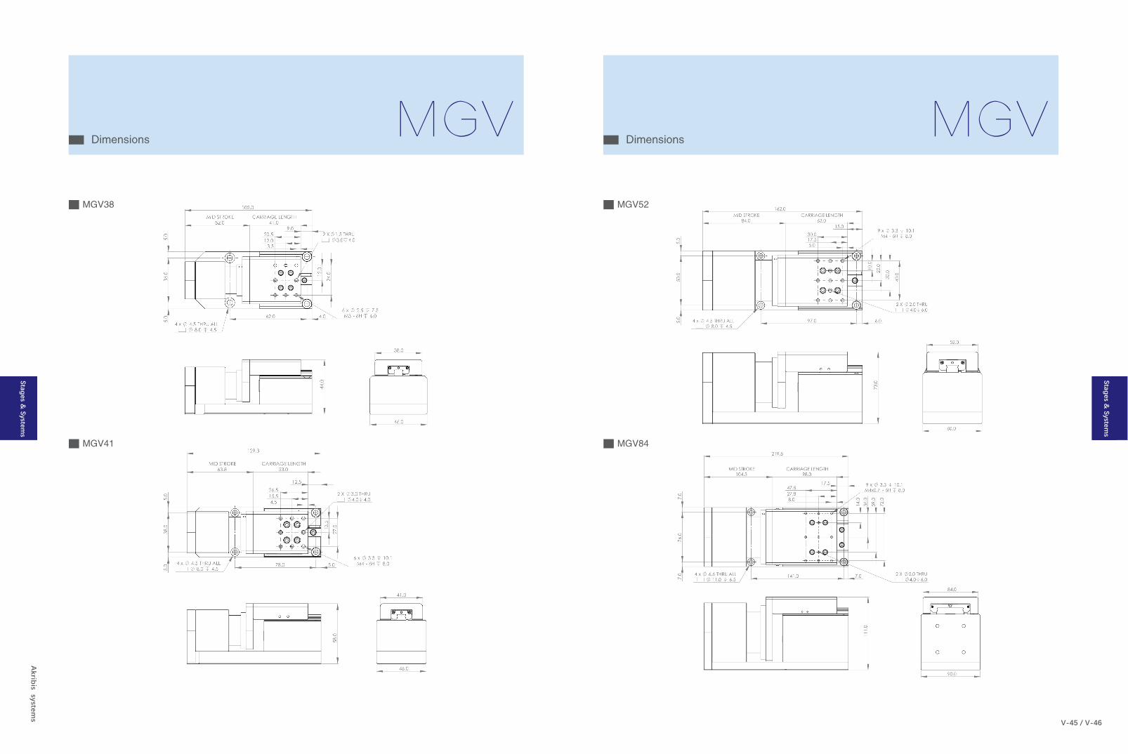
DimensionsMGV
Akrib
is systems
V-45 / V-46
DimensionsMGV
MGV38
MGV41
MGV52
MGV84
Stages & System
s
Stages & System
s
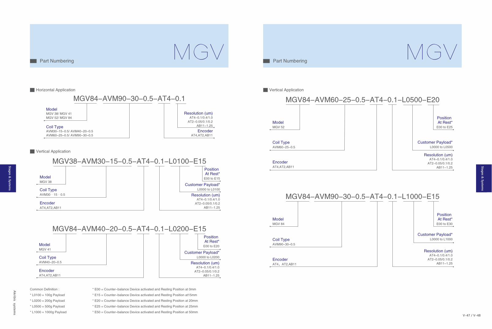
ModelMGV 38/ MGV 41MGV 52/ MGV 84
Coil TypeAVM30-15-0.5/ AVM40-20-0.5AVM60-25-0.5/ AVM90-30-0.5
MGV84-AVM90-30-0.5-AT4-0.1
Resolution (um)AT4-0.1/0.4/1.0
AT2-0.05/0.1/0.2AB11-1.25
EncoderAT4,AT2,AB11
Common Definition :
* L0100 = 100g Payload
* L0200 = 200g Payload
* L0500 = 500g Payload
* L1000 = 1000g Payload
* E00 = Counter-balance Device activated and Resting Position at 0mm
* E15 = Counter-balance Device activated and Resting Position at15mm
* E20 = Counter-balance Device activated and Resting Position at 20mm
* E25 = Counter-balance Device activated and Resting Position at 25mm
* E50 = Counter-balance Device activated and Resting Position at 50mm
Part NumberingMGV
Akrib
is systems
V-47 / V-48
Part NumberingMGV
Horizontal Application
ModelMGV 38
Position At Rest*
E00 to E15
Coil TypeAVM30–15–0.5
EncoderAT4,AT2,AB11
MGV38-AVM30-15-0.5-AT4-0.1-L0100-E15
Customer Payload*L0000 to L0100
Resolution (um)AT4-0.1/0.4/1.0
AT2-0.05/0.1/0.2AB11-1.25
Vertical Application
ModelMGV 41
Position At Rest*
E00 to E20
Coil TypeAVM40-20-0.5
EncoderAT4,AT2,AB11
MGV84-AVM40-20-0.5-AT4-0.1-L0200-E15
Customer Payload*L0000 to L0200
Resolution (um)AT4-0.1/0.4/1.0
AT2-0.05/0.1/0.2AB11-1.25
ModelMGV 52
Position At Rest*
E00 to E25
Coil TypeAVM60-25-0.5
EncoderAT4,AT2,AB11
MGV84-AVM60-25-0.5-AT4-0.1-L0500-E20
Resolution (um)AT4-0.1/0.4/1.0
AT2-0.05/0.1/0.2AB11-1.25
Customer Payload*L0000 to L0500
ModelMGV 84
Position At Rest*
E00 to E30
Coil TypeAVM90-30-0.5
EncoderAT4,AT2,AB11
MGV84-AVM90-30-0.5-AT4-0.1-L1000-E15
Customer Payload*L0000 to L1000
Resolution (um)AT4-0.1/0.4/1.0
AT2-0.05/0.1/0.2AB11-1.25
Vertical Application
Stages & System
s
Stages & System
s