MGE UPS SYSTEMS - Extranet Loginlit.powerware.com/ll_download.asp?file=Pulsar Evolution 500 to...
196
Installation and user manual English Français Deutsch Italiano Español Nederlands www.mgeups.com N O T H I N G W I L L S T O P Y O U N O W MGE UPS SYSTEMS Pulsar Evolution 1500 / 1500 Rack 1100 / 1100 Rack 800 / 800 Rack 500 Rack
Transcript of MGE UPS SYSTEMS - Extranet Loginlit.powerware.com/ll_download.asp?file=Pulsar Evolution 500 to...

3400711700/AB
Installation and usermanual
English
Français
Deutsch
Italiano
Español
Nederlands
www.mgeups.com
NO
TH
IN
G
WI
LL
ST
OP
YO
UN O W
MGE UPS SYSTEMS
Pulsar Evolution1500 /1500 Rack1100 /1100 Rack800 /800 Rack
500 Rack

34007117EN/AB - Page 1
Installation and usermanual
www.mgeups.com
NO
TH
IN
G
WI
LL
ST
OP
YO
UN O W
MGE UPS SYSTEMS
Pulsar Evolution1500 /1500 Rack1100 /1100 Rack800 /800 Rack
500 Rack

Page 2 - 34007117EN/AB

34007117EN/AB - Page 3
Introduction
Thank you for selecting an MGE UPS SYSTEMS product to protect your electrical equipment.
The Pulsar Evolution range has been designed with the utmost care. We recommend that you take the time to read thismanual to take full advantage of the many features of your UPS.
MGE UPS SYSTEMS pays great attention to the environmental impact of its products. Measures that have made PulsarEvolution a reference in environmental protection include:◗ the eco-design approach used in product development,◗ recycling of Pulsar Evolution at the end of its service life.
To discover the entire range of MGE UPS SYSTEMS products and the options available for the Pulsar Evolution range,we invite you to visit our web site at www.mgeups.com or contact your MGE UPS SYSTEMS representative.
Important: before installing and using the UPS, always read the safety instructions (document n° 3400722200).

Page 4 - 34007117EN/AB
Foreword
Using this document
Important instructions that must always be followed.
Information, advice, help.
Visual indication.
Action.
Audio indication.
In the illustrations on the following pages, the symbols below are used:
LED off.
LED on.
LED flashing.
Information may be found in two ways, using:◗ the contents;◗ the index.
Pictograms
34007117EN/AB - Page 5
Contents
1. Presentation1.1 Overall view ................................................................................................................................. 7
Tower models .................................................................................................................................. 7
Rack models ................................................................................................................................... 7
1.2 Back ............................................................................................................................................. 8
1.3 Control panel ................................................................................................................................. 9
2. Installation2.1 Unpacking and parts check ....................................................................................................... 10
Tower models ................................................................................................................................ 10
Rack models ................................................................................................................................. 11
2.2 Installation ................................................................................................................................... 12
Tower models ................................................................................................................................ 12
800/1100/1500 Rack models ........................................................................................................ 13
500 Rack model ............................................................................................................................ 14
2.3 Connecting the protected equipment ....................................................................................... 15
2.4 Connection to the RS232 or USB communications port (optional) ......................................... 16
2.5 Connection to the data-line protection port (optional) ............................................................. 16
2.6 Installation of the communications-card option ...................................................................... 17
3. Operation3.1 Start-up ........................................................................................................................................ 18
3.2 Shift to booster or fader mode (during voltage variations in the AC-input power) ..................... 18
3.3 Operation on battery power (following failure of AC-input power) ............................................. 19
Transfer to battery power .............................................................................................................. 19
Threshold for the low-battery warning ........................................................................................... 19
3.4 Personalisation (optional) ........................................................................................................... 20
Function ........................................................................................................................................ 20
ON / OFF conditions tab ............................................................................................................... 20
Battery tab ..................................................................................................................................... 20
Voltage-thresholds tab .................................................................................................................. 21
Sensitivity tab ................................................................................................................................ 21

Page 6 - 34007117EN/AB
Contents
4. Maintenance4.1 Trouble-shooting......................................................................................................................... 22
4.2 Replacement of the battery module .......................................................................................... 23
Tower models ................................................................................................................................ 23
Rack models ................................................................................................................................. 25
5. Environment ..................................................................................................................................... 27
6. Appendices6.1 Technical data ............................................................................................................................. 28
Simplified diagram ........................................................................................................................ 26
Technical characteristics ............................................................................................................... 29
Examples of battery backup times ................................................................................................ 30
6.2 Glossary ....................................................................................................................................... 31
6.3 Index............................................................................................................................................. 32

34007117EN/AB - Page 7
1. Presentation
1.1 Overall viewTower models
Rack models
Evolution 800
Evolution 1100
Evolution 1500
Weight in kg
10.5
11.5
15
Evolution 500 Rack
Evolution 800 Rack
Evolution 1100 Rack
Evolution 1500 Rack
Evolution 500 Rack
Evolution 800 Rack
Evolution 1100 Rack
Evolution 1500 Rack
Dimensions in mm(W x H x D)
438 x 43.5 x 353
438 x 43.5 x 499
438 x 43.5 x 499
438 x 43.5 x 522(19") (1U)
Weight in kg
9
15.5
16
19
Evolution 800
Evolution 1100
Evolution 1500
Dimensions in mm(W x H x D)
150 x 237 x 415
150 x 237 x 415
150 x 237 x 483
P U L S A R
Evolution
1 1 0 0
W
H
D
W
H
D
P U L S A R
Evolution
1500 Rack

Page 8 - 34007117EN/AB
1. Presentation
1.2 Back
Pulsar Evolution 500 / 800 / 1100 Rack
USB communications port.
RS232 communications port.
Data-line protection.
Slot for communications-card option.
Outlets for direct connection ofprotected equipment.
Programmable outlets (1 and 2).
Input circuit-breaker.
Socket for connection to AC-powersource.
1
2
3
4
5
6
7
8
1238 45
1 2
Pulsar Evolution 800 / 1100 / 1500
1
2
3
4
6
5
2
1
Pulsar Evolution 1500 Rack
8
6
12 384 5
1 2
6
7
7
7
Pulsar Evolution 1500:

34007117EN/AB - Page 9
1 2
%%
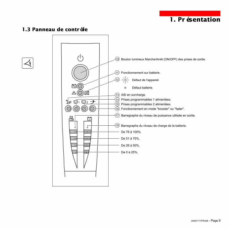
1.3 Control panel
Bargraph indicating percent load at output.
Group 1 programmable outlets supplied with power.
Iluminated ON/OFF button for the outlets.
Group 2 programmable outlets supplied with power.
Operation on battery power.
10
11
12
15
14
18
17
13
16
1. Presentation
UPS fault.
Battery fault.
Overload.
Booster or fader mode.
Bargraph indicating the battery charge level.
0 to 25%.
26 to 50%.
51 to 75%.
76 to 100%.

Page 10 - 34007117EN/AB
2. Installation
2.1 Unpacking and parts check
Two cords for connection of the protected equipment.
RS232 communications cable.
USB communications cable.
CD-ROM with the Solution-Pac and UPS Driver software.
Product documentation.
23
21
20
21
22
23
24
2220
24
30
Tower models
P U L S A R
Evolution
1 1 0 0

34007117EN/AB - Page 11
2. Installation
Two cords for connection of the protected equipment.
RS232 communications cable.
USB communications cable.
CD-ROM with the Solution-Pac and UPS Driver software.
Product documentation.
Telescopic rails for mounting in 19" bay with mounting hardware.
Securing system for equipment power cords.
20
21
22
23
24
25
26
26
21 2220
2423 25
Rack models
P U L S A R
Evolut ion
1500 Rack

Page 12 - 34007117EN/AB
2. Installation
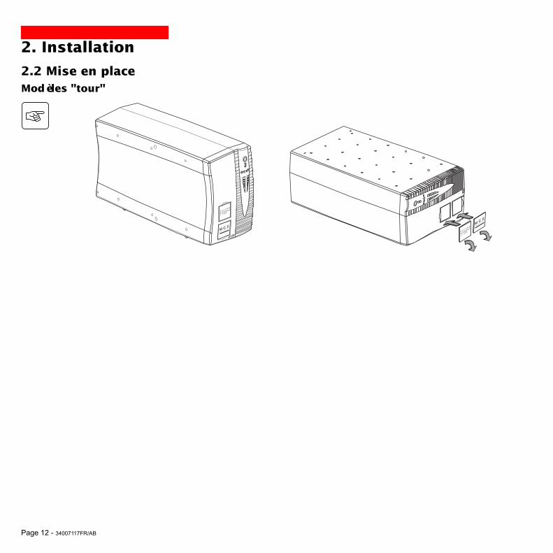
2.2 InstallationTower models
P U L S A
R
Evolutio
n
1 1 0 0
P U L S A R
Evolution
1 1 0 0
34007117EN/AB - Page 13
2. Installation
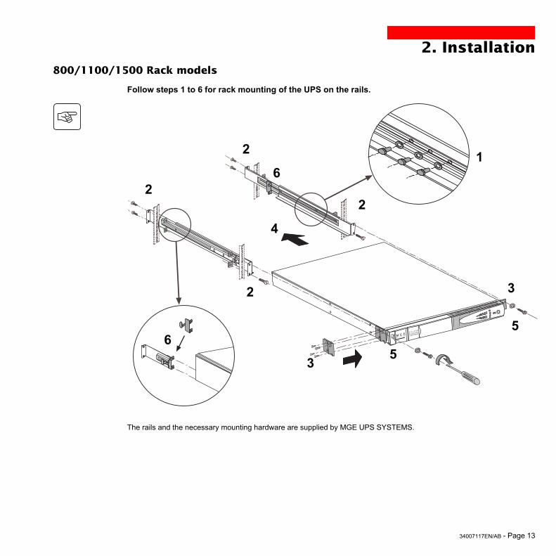
Follow steps 1 to 6 for rack mounting of the UPS on the rails.
The rails and the necessary mounting hardware are supplied by MGE UPS SYSTEMS.
12
22
2
53
6
6
5
4
3
800/1100/1500 Rack models
P U L S A R
Evolution
1500 Rack

Page 14 - 34007117EN/AB
2. Installation500 Rack model
1
2
3
3
1
P U L S A R
Evolution
1500 Rack
P U L S A R
Evolution
1500 Rack
P U L S A R
Evolution
1500 Rack
34007117EN/AB - Page 15
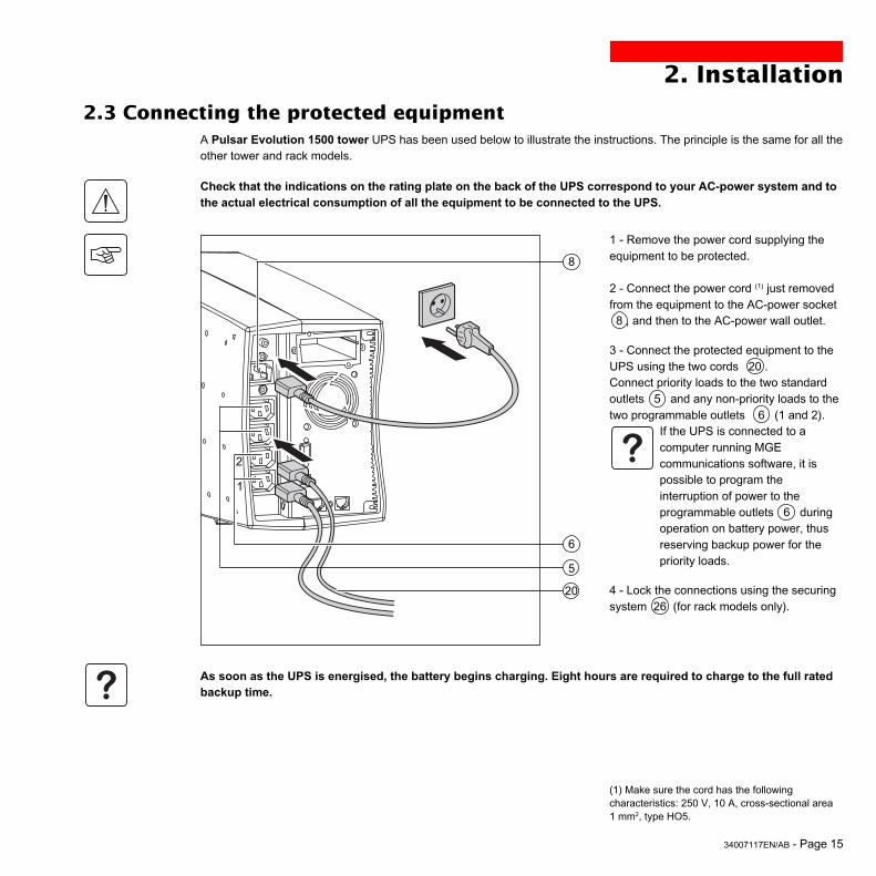
2.3 Connecting the protected equipment
Check that the indications on the rating plate on the back of the UPS correspond to your AC-power system and tothe actual electrical consumption of all the equipment to be connected to the UPS.
1 - Remove the power cord supplying theequipment to be protected.
2 - Connect the power cord (1) just removedfrom the equipment to the AC-power socket␣ ␣ 8 , and then to the AC-power wall outlet.
3 - Connect the protected equipment to theUPS using the two cords 20 .Connect priority loads to the two standardoutlets ␣ 5 and any non-priority loads to thetwo programmable outlets ␣ ␣ 6 (1 and 2).
If the UPS is connected to acomputer running MGEcommunications software, it ispossible to program theinterruption of power to theprogrammable outlets 6 duringoperation on battery power, thusreserving backup power for thepriority loads.
4 - Lock the connections using the securingsystem 26 (for rack models only).
5
6
2. Installation
8
As soon as the UPS is energised, the battery begins charging. Eight hours are required to charge to the full ratedbackup time.
(1) Make sure the cord has the followingcharacteristics: 250 V, 10 A, cross-sectional area1␣ mm2, type HO5.
20
2
1
A Pulsar Evolution 1500 tower UPS has been used below to illustrate the instructions. The principle is the same for all theother tower and rack models.

Page 16 - 34007117EN/AB
RS232
2. Installation
2.4 Connection to the RS232 or USB communications port (optional)
1 - Connect the RS232 21 or USB 22communications cable to the serial port orthe USB port on the computer.
2 - Connect the other end of thecommunications cable 21 or 22 to theRS232 2 or USB 1 communicationsport on the UPS.
The UPS can now communicate with allMGE UPS SYSTEMS supervision, set-up orsafety software.
21
22
The RS232 and USBcommunications ports cannotoperate simultaneously.
2.5 Connection to the data-line protection port (optional)The data-line protection function on the UPSeliminates overvoltages flowing on thecomputer-network lines.Simply connect the line to be protected tothe UPS using the data-line protectionconnectors (IN and OUT) as indicatedopposite (RJ45 cables not supplied).
1
2
IN OUT
RS232
DATA LINEPROTECTION
A Pulsar Evolution 1500 tower UPS has been used below to illustrate the instructions. The principle is the same for all theother tower and rack models.

34007117EN/AB - Page 17
2. Installation
2.6 Installation of the communications-card option
1 - Remove the slot cover 4 secured bytwo screws.
2 - Insert the card in the slot.
3 - Secure the cover with the two screws.
Restricted-access slot forthe communications card
4
IN OUTDATA LINE PROTECTION
RS232
It is not necessary to shut down the UPS to install the communications card.This operation must be carried out by qualified personnel.

Page 18 - 34007117EN/AB
1 2
%%
3. Operation
3.1 Start-up
10
11
12
Press the ON / OFF button 10 .The buzzer beeps and all the LEDs come ON.The buzzer beeps twice during the self-test, then button 10 remainsON, indicating that the outlets are supplied with power.- AC power is present: Only button 10 is ON. The protectedequipment is supplied by the AC-power source.- AC power is absent: Button 10 and LED 11 are ON. The protectedequipment is supplied by the UPS, operating on battery power.
All the connected equipment is supplied with power.
1 2
%%
3.2 Shift to booster or fader mode(during voltage variations in the AC-input power)
16
The booster and fader functions maintain the output voltage supplied bythe UPS within close tolerances around the rated value even ifsignificant voltage variations occur in the AC-input power. This avoidscalling on battery power.The values defining the voltage range may be set using the UPS Driversoftware.During operation in booster or fader mode, LED 16 is ON, signalling asignificant voltage variation in the AC-input power.
If button 10 or LED 11 are not ON or if LED 12 is ON, there is a fault (see section 4.1).Note: The battery is charged as soon as the UPS is connected to the AC-power source, even if button 10 is in the OFFposition.

34007117EN/AB - Page 19
1 2
%%
1 2
%%
3. Operation
3.3 Operation on battery power (following failure of AC-input power)Transfer to battery power
The AC-input power is out of tolerances, LED 11 goes ON.During operation on battery power, the buzzer beeps every ten seconds.
The equipment connected to the UPS is supplied by the battery.
Threshold for the low-battery warningWhen the threshold is reached, the buzzer beeps every three seconds.The low-battery warning threshold can be set by the user, with the “UPSDriver” software.
There is very little remaining battery backup time. Close allapplications because UPS automatic shutdown is imminent.
When the battery reaches the end of its backup time, the UPS shutsdown and all the LEDs go OFF.
The equipment is no longer supplied with power.
11
The UPS automatically restarts when power returns.If the UPS does not restart, check that the “automatic restart when power returns” function has not been disabled (seesection 3.4 Personalisation).
11

Page 20 - 34007117EN/AB
3. Operation
3.4 Personalisation (optional)
Function
Configurable function
Automatic restart
Cold start
Forced reboot
Energy saving
UPS ON / OFF via software
Default setting
Enabled
Enabled
Enabled
Disabled
Enabled
Personalisation parameters can be set and modified using the UPS Driver software installed on a computer that isconnected to the UPS (see section 2.4 Connection to the RS232 communications port).
Check that the RS232 21 communications cable is connected.
UPS Driver installation:
1 - Insert the Solution-Pac CD-ROM containing the UPS Driver software in the drive of a PC running Windows.2 - Open the Windows File manager or Explorer and select the CD-ROM drive.3 - Double-click "\Emb\Evolutio\Config\upsdriv.exe".
Once UPS Driver has been installed, UPS parameters can be modified in a window containing a number of tabs, eachpresenting a set of parameters :
Battery tab
Configurable function
Interval between automatic battery tests
Low-battery warning threshold
Protection against deep discharges
Default setting
Once a week
20% of the remaining batterybackup time
Enabled
Options
Every dayOnce a month
No test
10 to 40% of the remaining batterybackup time
Disabled
Options
Disabled
Disabled
Disabled
Enabled
Disabled
ON / OFF conditions tab

34007117EN/AB - Page 21
3. Operation
Configurable function
Output voltage on battery power
Upper threshold for transfer to battery power
Fader-mode cut-in threshold
Booster-mode cut-in threshold
Lower threshold for transfer to battery power
Maximum input-voltage range
Default setting
230 V
294 V
265 V
184 V
160 V
Disabled
Options
200 V - 220 V - 240 V
271 to 294 V
244 to 265 V
184 to 207 V
160 to 180 V
Enabled (1)
Configurable function
UPS sensitivity level
Default setting
Normal
Options
High or low
Voltage-thresholds tab
Sensitivity tab
For more informations about these settings, refer to the Help function of the "UPS Driver" software.
(1) Lower threshold for transfer to battery power = 150 V

Page 22 - 34007117EN/AB
Troubleshooting requiring MGE UPS SYSTEMS after-sales support
4. Maintenance
4.1 Trouble-shooting
Indication
LED 12 goes ON andthe buzzer soundscontinuously.
Signification
UPS electronics have detected a UPS fault.◗ The connected equipment is no longer supplied.
The equipment connected to the UPS is no longer protected.
Correction
Call the after-sales supportdepartment.
Indication
LED 13 flashes and thebuzzer beeps once.
LED 12 flashes.
Signification
UPS overload. The power drawn by the connectedequipment exceeds UPS capacity.
A battery fault was detected during the automaticbattery test.
Correction
Check the power drawn by theequipment and disconnect any non-priority devices.
Replace the battery module (seesection 4.2).
Troubleshooting not requiring MGE UPS SYSTEMS after-sales support (all versions)

34007117EN/AB - Page 23
P U L S A R
Evolution
1 5 0 0
B
A
C
4.2 Replacement of the battery module
4. Maintenance
Removal of the battery moduleThis operation may be carried out with the UPS supplying power to the load.
Safety rulesBatteries constitute a danger (electrical shock, burns). The short-circuit current may be very high. Precautionsmust be taken for all handling:◗ remove all watches, rings, bracelets and any other metal objects;◗ use tools with insulated handles.
A - Unclip the small plate with the MGElogo on the front panel of the UPS. B - Remove the two screws. C - Remove the left-hand side of the frontpanel by pulling it slightly up and thenforward.
Tower models
D
D - Disconnect the battery module bypulling apart the connectors (never pull onthe cables).

Page 24 - 34007117EN/AB
4. Maintenance
Installation of the new battery moduleCarry out the above operation in reverse order.
◗ Caution: risk of electric arc when connecting the battery.◗ To maintain an identical level of performance and safety, use a battery module identical to that previouslymounted in the UPS.◗ Press the two parts of the battery connector tightly together to ensure proper connection.
E - Remove the battery module by pullingon the plastic tab and proceed withreplacement.
E

34007117EN/AB - Page 25
D
A
BC
P U L S A R
Evolution
1 5 0 0
4. Maintenance
Removal of the battery moduleThis operation may be carried out with the UPS supplying power to the load.
A - Unclip the small plate with the MGElogo on the front panel of the UPS. B - Remove the two screws. C - Remove the left-hand side of the frontpanel by pulling it forward.
D - Disconnect the battery module bypulling apart the connectors (never pull onthe cables).
Rack models

Page 26 - 34007117EN/AB
F
E
4. Maintenance
Installation of the new battery moduleCarry out the above operation in reverse order.
◗ Caution: risk of electric arc when connecting the battery.◗ To maintain an identical level of performance and safety, use a battery module identical to that previouslymounted in the UPS.◗ Press the two parts of the battery connector tightly together to ensure proper connection.
E - Remove the cover.
F - Remove the battery module by pullingon the plastic tab and proceed withreplacement.

34007117EN/AB - Page 27
5. EnvironmentThis product has been designed to respect the environment:
It does not contain CFCs or HCFCs.
UPS recycling at the end of service life:
MGE UPS SYSTEMS undertakes to recycle, by certified companies and in compliance with all applicable regulations, allUPS products recovered at the end of their service life (contact your MGE branch office).
Packing:
UPS packing materials must be recycled in compliance with all applicable regulations.
Warning:
This product contains lead-acid batteries. Lead is a dangerous substance for the environment if it is not properly recycledby specialised companies.
Web site: www.mgeups.com

Page 28 - 34007117EN/AB
6. Appendices
6.1 Technical dataSimplified diagram
Input
Output
Battery
ChargerInverter
Booster / fader transformerFilter

34007117EN/AB - Page 29
6. AppendicesTechnical characteristics
(1) The upper and lower thresholds may be set using the UPS Driver software.(2) Or 40 Hz in low-sensitivity mode (may be set using the UPS Driver software).(3) Adjustable from 200 to 240 V using the UPS Driver software.
Output rating
AC-input power◗ Voltage◗ Frequency
Output power (operationon battery power)◗ Voltage◗ Frequency
Battery (sealed lead-acid,maintenance free)◗ Tower models◗ Rack models
Environment◗ Noise level (operation onAC-input power)◗ Operating temperature◗ Relative humidity(without condensation)
Pulsar Evolution 500
500 VA / 350 W
2 x 6 V - 9 Ah,
1100 / 1100 rack
1100 VA / 700 W
2 x 12 V - 9 Ah,4 x 6 V - 9 Ah
800 / 800 rack
800 VA / 560 W
2 x 12 V - 7.2 Ah,4 x 6 V - 7.2 Ah
1500 / 1500 rack
1500 VA / 1000 W
3 x 12 V - 9 Ah,6 x 6 V - 9 Ah
Single-phase, 160 V to 294 V (1) , 230V nominal.
Single-phase, 230 V (3) (+ 6% / - 10%)50/60 Hz +/- 0.1 Hz
<40 dBA
0 to 35° C
20 to 90%
<40 dBA
0 to 40° C
20 to 90%
47 Hz to 70 Hz (50 Hz system) or 56.5 Hz to 70 Hz (2) (60 Hz system)

Page 30 - 34007117EN/AB
6. AppendicesExamples of battery backup times
Pulsar Evolution 500
Pulsar Evolution 800
Pulsar Evolution 1100
1 hub
1 router
1 data server + 1 hub + 1 router
Pulsar Evolution 1500
2 file/print servers
0 10 20 50 100 t (min)30 40 60 70 80 90 110 120
0 10 20 50 100 t (min)30 40 60 70 80 90 110 120
2 rack-optimized dense servers
3 rack-optimized dense servers
1 hub
1 router
1 data server + 1 hub + 1 router
2 file/print servers
3 rack-optimized dense servers
1 hub
1 router
5 rack-optimized dense servers
3 file/print servers
2 data servers + 1 hub + 1 router
1 router
0 10 20 50 100 t (min)30 40 60 70 80 90 110 120
0 10 20 50 100 t (min)30 40 60 70 80 90 110 120

34007117EN/AB - Page 31
6. Appendices
6.2 GlossaryBackup time Time that the connected equipment can operate on battery power if AC-input power fails.
Bargraph Device on the front panel indicating the percent remaining backup time or the percentload.
Booster mode Automatic UPS operating mode whereby the input-power voltage is increased if it dropsbelow a value set in the personalisation parameters, thus avoiding a battery discharge.
De-energised The UPS must be physically disconnected from the AC-input power.
Equipment Devices and systems connected to the UPS output.
Fader mode Automatic UPS operating mode whereby the input-power voltage is decreased if it risesabove a value set in the personalisation parameters, thus avoiding a battery discharge.
Input circuit breaker Circuit breaker protecting the upstream distribution system against UPS faults.
Outlets Pulsar Evolution has a group of four non-programmable outlets.
Personalisation The parameters for a number of UPS functions may be modified using the UPS Driversoftware to adapt UPS operation to user needs.
Programmable outlets Pulsar Evolution has two groups of two programmable outlets. They may be used forsequential start-up of protected equipment, shedding of non-priority loads duringoperation on battery power or management of operating priorities to provide the mostcritical devices with more backup time before battery power runs out. These outlets maybe programmed using the Solution-Pac software on the CD-ROM supplied with theUPS.
RS232 communications port For UPS connection to a computer via the serial port.
Solution-Pac MGE UPS SYSTEMS safety, set-up and supervision software suite on the CD-ROMsupplied with the UPS.
UPS Uninterruptible Power Supply.
UPS Driver Communications software on the CD-ROM supplied with the UPS. It may be used topersonalise the default settings.
USB communications port For UPS connection to a computer via the USB port.

Page 32 - 34007117EN/AB
6. Appendices
6.3 IndexAAutomatic start ............................................................... 20
BBargraph .......................................................................... 9Battery
Backup time ............................................................ 30End of backup time ................................................. 19Fault ......................................................................... 9Personalisation ....................................................... 20Recycling ................................................................ 27Replacement .............................................. 22, 23, 24Threshold for low-battery warning .......................... 19Transfer to battery power ................................... 9, 19
Buttons ............................................................................. 9Buzzer ............................................................................ 19
CCircuit breakers
Battery circuit breaker .............................................. 8Input circuit breaker .................................................. 8
CommunicationCards .................................................................. 8, 17Ports ................................................................... 8, 16
ConnectionsData-line protection ................................................ 16RS232 communications port .................................. 16USB communications port ...................................... 16
DDimensions ...................................................................... 7
EEnvironment ................................................................... 27
FFault (UPS) ...................................................................... 9
LLEDs ................................................................................ 9
MMode
Booster mode ..................................................... 9, 18Fader mode ........................................................ 9, 18Sleep mode (automatic start) ................................. 20
OOverloads ................................................................... 9, 22
PPersonnalisation ........................................................... 20
Battery .................................................................... 20ON / OFF conditions .............................................. 20Output .................................................................... 21
PortsRS232 ................................................................8, 16USB ....................................................................8, 16
Programmable outlets .................................................. 8, 9
SSafety ............................................................................. 23Start-up .......................................................................... 18
TTechnical characteristics ................................................ 29Temperature (excessive ambient) .................................. 29
UUPS Driver .................................................. 18, 19, 20, 29UPS ON / OFF via software ........................................... 20
WWeb site ........................................................................ 27Weight .............................................................................. 7

34007117FR/AB - Page 1
Manuel d'installationet d'utilisation
www.mgeups.com
RI
EN
NE
DO
IT
VO
US
AR R Ê T E R
MGE UPS SYSTEMS
Pulsar Evolution1500 /1500 Rack1100 /1100 Rack800 /800 Rack
500 Rack

Page 2 - 34007117FR/AB

34007117FR/AB - Page 3
Introduction
Nous vous remercions d'avoir choisi un produit MGE UPS SYSTEMS pour assurer la sécurité des équipements qu'ilalimente.
La gamme Pulsar Evolution a été élaborée avec le plus grand soin.Pour exploiter au mieux les performances de l'ASI (Alimentation Sans Interruption), nous vous conseillons de prendre letemps de lire ce manuel.
MGE UPS SYSTEMS se préoccupe de l'impact de ses produits sur l'environnement.Les ressources mises en oeuvre font de Pulsar Evolution une référence en matière de protection de l'environnement donten particulier :◗ une démarche d'éco-conception pendant son cycle de développement,◗ le recyclage de Pulsar Evolution en fin de vie du produit.
Nous vous invitons à découvrir l'offre de MGE UPS SYSTEMS ainsi que les options de la gamme Pulsar Evolution envisitant notre site WEB à www.mgeups.com ou en contactant votre représentant MGE UPS SYSTEMS.
Important␣ : avant l’installation et l’utilisation de l’ASI, il est impératif de lire attentivement les consignes de sécurité(document n° 3400722200).

Page 4 - 34007117FR/AB
Avant propos
Structure de la documentation
Suivre impérativement ces consignes.
Informations, conseils, aide.
Signalisation visuelle.
Action.
Signalisation sonore.
Les conventions adoptées pour représenter les voyants dans les illustrations sont les suivantes :
Voyant éteint.
Voyant allumé.
Voyant clignotant.
La recherche d’information s’effectue de deux façons :◗ par le sommaire,◗ par l’index.
Conventions des pictogrammes

34007117FR/AB - Page 5
Sommaire
1. Présentation1.1 Vues générales ............................................................................................................................ 7
Modèles "tour" ................................................................................................................................. 7
Modèles "rack" ................................................................................................................................ 7
1.2 Faces arrières .............................................................................................................................. 8
1.3 Panneau de contrôle ..................................................................................................................... 9
2. Installation2.1 Déballage et vérification ............................................................................................................. 10
Modèles "tour" ............................................................................................................................... 10
Modèles "rack" .............................................................................................................................. 11
2.2 Mise en place............................................................................................................................... 12
Modèles "tour" ............................................................................................................................... 12
Modèles "rack" 800/1100/1500 ..................................................................................................... 13
Modèle "rack" 500 ......................................................................................................................... 14
2.3 Raccordement des équipements ............................................................................................... 15
2.4 Raccordement du port de communication RS232 ou USB (facultatif) .................................... 16
2.5 Raccordement de la protection ligne de données (facultatif) .................................................. 16
2.6 Mise en place de l’option "carte de communication" .............................................................. 17
3. Utilisation3.1 Mise en marche ........................................................................................................................... 18
3.2 Passage en mode "booster" ou "fader" (en cas de variation de tension du réseau électrique)18
3.3 Alimentation sur batterie (en cas d'absence du réseau électrique) ........................................... 19
Passage sur batterie ..................................................................................................................... 19
Seuil d’alarme de fin d’autonomie batterie atteint ......................................................................... 19
3.4 Personnalisation (facultatif) ........................................................................................................ 20
Fonction ........................................................................................................................................ 20
Onglet "Conditions On/Off" ........................................................................................................... 20
Onglet "Batterie" ........................................................................................................................... 20
Onglet "Seuils de tension" ............................................................................................................ 21
Onglet "Sensibilité" ....................................................................................................................... 21

Page 6 - 34007117FR/AB
Sommaire
4. Maintenance4.1 Dépannage ................................................................................................................................... 22
4.2 Remplacement du module batterie ........................................................................................... 23
Modèles "tour" ............................................................................................................................... 23
Modèles "rack" .............................................................................................................................. 25
5. Environnement ................................................................................................................................ 27
6. Annexes6.1 Caractéristiques techniques ...................................................................................................... 28
Schéma synoptique ...................................................................................................................... 26
Caractéristiques techniques .......................................................................................................... 29
Exemples d'autonomies batterie ................................................................................................... 30
6.2 Glossaire ...................................................................................................................................... 31
6.3 Index............................................................................................................................................. 32

34007117FR/AB - Page 7
1. Présentation
1.1 Vues généralesModèles "tour"
Modèles "rack"
Evolution 800
Evolution 1100
Evolution 1500
Poids en kg
10,5
11,5
15
Evolution 500 Rack
Evolution 800 Rack
Evolution 1100 Rack
Evolution 1500 Rack
Evolution 500 Rack
Evolution 800 Rack
Evolution 1100 Rack
Evolution 1500 Rack
Dimensions en mm(L x H x P)
438 x 43,5 x 353
438 x 43,5 x 499
438 x 43,5 x 499
438 x 43,5 x 522(19") (1U)
Poids en kg
9
15,5
16
19
Evolution 800
Evolution 1100
Evolution 1500
Dimensions en mm(L x H x P)
150 x 237 x 415
150 x 237 x 415
150 x 237 x 483
P U L S A R
Evolution
1 1 0 0
L
H
P
L
H
P
P U L S A R
Evolut ion
1500 Rack

Page 8 - 34007117FR/AB
1. Présentation
1.2 Faces arrières
Pulsar Evolution 500 / 800 / 1100 Rack
Port de communication USB.
Port de communication RS232.
Protection des lignes de données.
Emplacement pour l'option "carte decommunication".
Prises pour le raccordement deséquipements.
Prises programmables (1 et 2).
Disjoncteur de protection du réseauélectrique d'alimentation.
Prise pour le raccordement au réseauélectrique d'alimentation.
1
2
3
4
5
6
7
8
1238 45
1 2
Pulsar Evolution 800 / 1100 / 1500
1
2
3
4
6
5
2
1
Pulsar Evolution 1500 Rack
8
6
12 384 5
1 2
6
7
7
7
Pulsar Evolution 1500 :
34007117FR/AB - Page 9
1 2
%%
1.3 Panneau de contrôle
Barregraphe du niveau de puissance utilisée en sortie.
Prises programmables 1 alimentées.
Bouton lumineux Marche/Arrêt (ON/OFF) des prises de sortie.
Prises programmables 2 alimentées.
Fonctionnement sur batterie.
10
11
12
15
14
18
17
13
16
1. Présentation
Défaut de l'appareil.
Défaut batterie.
ASI en surcharge.
Fonctionnement en mode "booster" ou "fader".
Barregraphe du niveau de charge de la batterie.
De 0 à 25%.
De 26 à 50%.
De 51 à 75%.
De 76 à 100%.

Page 10 - 34007117FR/AB
2. Installation
2.1 Déballage et vérification
2 cordons pour raccorder les équipements.
Câble de communication RS 232.
Câble de communication USB.
CD ROM contenant les logiciels "Solution Pac" et "UPS Driver".
Documentation.
23
21
20
21
22
23
24
2220
24
30
Modèles "tour"
P U L S A R
Evolution
1 1 0 0

34007117FR/AB - Page 11
2. Installation
2 cordons pour raccorder les équipements.
Câble de communication RS 232.
Câble de communication USB.
CD ROM contenant les logiciels "Solution Pac" et "UPS Driver".
Documentation.
Kit de montage en armoire 19".
Système de verrouillage des cordons d'alimentation des équipements.
20
21
22
23
24
25
26
26
21 2220
2423 25
Modèles "rack"
P U L S A R
Evolut ion
1500 Rack
Page 12 - 34007117FR/AB
2. Installation
2.2 Mise en placeModèles "tour"
P U L S A
R
Evolutio
n
1 1 0 0
P U L S A R
Evolution
1 1 0 0

34007117FR/AB - Page 13
2. Installation
Montage et fixation des glissières et du rack : suivre les étapes 1 à 6.
La visserie de fixation et les glissières sont fournies par MGE UPS SYSTEMS.
12
22
2
53
6
6
5
4
3
Modèles "rack" 800/1100/1500
P U L S A R
Evolution
1500 Rack

Page 14 - 34007117FR/AB
2. InstallationModèles "rack" 500
1
2
3
3
1
P U L S A R
Evolution
1500 Rack
P U L S A R
Evolution
1500 Rack
P U L S A R
Evolution
1500 Rack

34007117FR/AB - Page 15
2.3 Raccordement des équipements
Vérifier que les indications portées sur la plaque d'identification située à l'arrière de l'appareil correspondent auréseau électrique d'alimentation et à la consommation électrique réelle des équipements.
1 - Débrancher le cordon d'alimentation del'équipement.
2 - Connecter ce cordon(1) sur la prise 8 ,puis sur la prise du réseau électriqued'alimentation.
3 - Raccorder les équipements à l'ASI àl'aide des cordons 20 .Connecter de préférence les équipementsprioritaires sur les 2 prises ␣ 5 et leséquipements non prioritaires sur les 2 prises␣ ␣ 6 programmables (1 et 2).
Pour pouvoir programmer l'arrêtdes prises ␣ ␣ 6 en coursd'autonomie batterie et optimiserainsi la durée de cette autonomie,il est nécessaire d'avoir accès aulogiciel de communication MGEUPS SYSTEMS.
4 - Verrouiller le raccordement en fixant lesystème 26 (pour les modèles "rack"uniquement).
5
6
2. Installation
8
Après la première mise sous tension, il faut au moins 8␣ heures pour que la batterie puisse fournir l'autonomienominale.
(1) S'assurer que les caractéristiques de ce cordonsont : 250V - 10A (section 1mm2, type HO5).
20
2
1
Les consignes ci-dessous sont illustrées par des vues d'un modèle Pulsar Evolution 1500 "tour". Le principe est identiquepour les autres modèles "tour" et "rack".
Page 16 - 34007117FR/AB
RS232
2. Installation
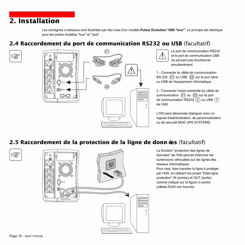
2.4 Raccordement du port de communication RS232 ou USB (facultatif)
1 - Connecter le câble de communicationRS␣ 232 21 ou USB 22 sur le port sérieou USB de l'équipement informatique.
2 - Connecter l'autre extrémité du câble decommunication 21 ou 22 sur le portde communication RS232 2 ou USB 1de l’ASI.
L'ASI peut désormais dialoguer avec unlogiciel d'administration, de personnalisationou de sécurité MGE UPS SYSTEMS.
21
22
Le port de communication RS232et le port de communication USBne peuvent pas fonctionnersimultanément.
2.5 Raccordement de la protection de la ligne de données (facultatif)La fonction "protection des lignes dedonnées" de l'ASI permet d'éliminer lessurtensions véhiculées sur les lignes desréseaux informatiques.Pour cela, faire transiter la ligne à protégerpar l'ASI, en utilisant les prises "Data ligneprotection" IN (entrée) et OUT (sortie)comme indiqué sur la figure ci-contre(câbles RJ45 non fournis).
1
2
IN OUT
RS232
DATA LINEPROTECTION
Les consignes ci-dessous sont illustrées par des vues d'un modèle Pulsar Evolution 1500 "tour". Le principe est identiquepour les autres modèles "tour" et "rack".
34007117FR/AB - Page 17
2. Installation
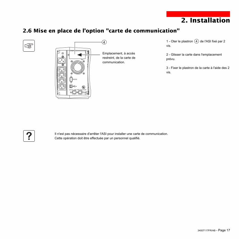
2.6 Mise en place de l’option "carte de communication"
1 - Oter le plastron 4 de l'ASI fixé par 2vis.
2 - Glisser la carte dans l'emplacementprévu.
3 - Fixer le plastron de la carte à l'aide des 2vis.
Emplacement, à accèsrestreint, de la carte decommunication.
4
Il n'est pas nécessaire d'arrêter l'ASI pour installer une carte de communication.Cette opération doit être effectuée par un personnel qualifié.
IN OUTDATA LINE PROTECTION
RS232

Page 18 - 34007117FR/AB
1 2
%%
3. Utilisation
3.1 Mise en marche
10
11
12
Appuyer sur le bouton 10 .Le buzzer émet un bip et tous les voyants s'allument simultanément.Le buzzer émet ensuite 2 bips pendant l'autotest, puis le bouton 10reste allumé signalant l'alimentation des prises de sortie.- Réseau électrique d'alimentation présent : seul le bouton 10 estallumé. Les équipements sont alimentés par le réseau électrique.- Réseau électrique d'alimentation absent : le bouton 10 et le voyant␣ 11 sont allumés. Les équipements sont alimentés par l'ASI quifonctionne sur batterie.
L’ensemble des équipements connectés est alors sous tension.
1 2
%%
3.2 Passage en mode "booster" ou "fader"(en cas de variation de tension du réseau électrique)
16
Les fonctions "booster" et "fader" permettent de maintenir la tension desortie délivrée par l'ASI dans une plage définie autour de la valeurnominale, en cas de variation d'amplitude plus importante du réseauélectrique d'alimentation, et ceci sans décharger la batterie.Les valeurs de cette plage de fonctionnement sont configurables parl'intermédiaire du logiciel "UPS Driver".Lors du fonctionnement en mode "booster" ou "fader", le voyant 16 estallumé, indiquant une variation d'amplitude importante du réseauélectrique d'alimentation.
Si les voyants 10 ou 11 ne s’allument pas ou si le voyant ␣ 12 est allumé, un défaut est présent (voir chapitre 4.1).
Nota : l'appareil recharge la batterie dès qu'il est raccordé au réseau électrique, même sans appuyer sur le bouton 10 .

34007117FR/AB - Page 19
1 2
%%
1 2
%%
3. Utilisation
3.3 Alimentation sur batterie (en cas d’absence du réseau électrique)Passage sur batterie
Lorsque le réseau électrique d'alimentation est hors tolérances, levoyant 11 est allumé.Durant toute la durée de l'autonomie batterie, le buzzer émet un biptoutes les 10 secondes.
Les équipements connectés à l’ASI continuent d’être alimentésgrâce à la batterie.
Seuil d’alarme de fin d’autonomie batterie atteintLorsque ce seuil est atteint, le buzzer émet un bip toutes les 3 secondes.Ce seuil peut se personnaliser via le logiciel "UPS Driver".
Il ne reste alors qu’une faible partie d’autonomie batterie, fermezles applications car l’arrêt automatique de l’ASI est proche.
Lorsque la fin d'autonomie batterie est atteinte, l'ASI s'arrête et tous lesvoyants sont éteints.
Les équipements connectés à l’ASI ne sont plus alimentés.
11
L'ASI redémarre automatiquement dès le retour du réseau électrique.Si l’ASI ne redémarre pas, vérifiez que le redémarrage automatique sur retour du réseau électrique n’a pas été désactivé(voir le chapitre 3.4 "Personnalisation").
11

Page 20 - 34007117FR/AB
3. Utilisation
3.4 Personnalisation (facultatif)
Fonction
Fonctions personnalisables
Redémarrage automatique
Démarrage sur batterie ("cold start")
Arrêt forcé
Mise en veille
Marche/Arrêt onduleur par logiciel
Configuration usine
Activé
Activé
Activé
Désactivé
Activé
Il est possible de faire évoluer la personnalisation de l'ASI au moyen du logiciel "UPS Driver" installé sur un ordinateurconnecté à l’ASI selon la procédure "Raccordement du port de communication RS232" (voir chapitre 2.4).
Vérifier que le câble RS 232 21 est raccordé.
Installation du logiciel "UPS Driver" :
1 - Insérer le CD ROM "Solution Pac" contenant le logiciel "UPS Driver" dans le lecteur de votre micro-ordinateurcompatible Windows.2 - Ouvrir le gestionnaire de fichier Windows ou l'explorateur et sélectionner le lecteur de CD ROM.3 - Lancer "\Emb\Evolutio\Config\Setup.exe".
Après avoir installé "UPS Driver", vous pouvez modifier les paramètres de réglage suivants :
Onglet "Batterie"
Fonctions personnalisables
Intervalle du test batterie automatique
Seuil "Alarme niveau bas" de la batterie
Protection contre les décharges profondes
Configuration usine
Toutes les semaines
20% de l’autonomie restante
Activé
Personnalisation possible
Tous les joursTous les moisPas de test
De 10 à 40% de l’autonomierestante
Désactivé
Personnalisation possible
Désactivé
Désactivé
Désactivé
Activé
Désactivé
Onglet "Conditions On/Off"

34007117FR/AB - Page 21
3. Utilisation
Fonctions personnalisables
Tension de sortie en fonctionnement sur batterie
Seuil haut de passage sur batterie
Seuil d'activation du mode "fader"
Seuil d'activation du mode "booster"
Seuil bas de passage sur batterie
Plage maximale de tension d'entrée
Configuration usine
230 V
294 V
265 V
184 V
160 V
Désactivé
Personnalisation possible
200 V - 220 V - 240 V
271 à 294 V
244 à 265 V
184 à 207 V
160 à 180 V
Activé (1)
Fonctions personnalisables
Niveau de sensibilité de l'ASI
Configuration usine
Normal
Personnalisation possible
Haute ou basse
Onglet "Seuils de tension"
Onglet "Sensibilité"
Pour plus d'informations concernant ces paramètres, se référer à la rubrique d'aide du logiciel "UPS Driver".
(1) Seuil bas de passage sur batterie = 150 V

Page 22 - 34007117FR/AB
Dépannage avec intervention du SAV
4. Maintenance
4.1 Dépannage
Symptôme
Le voyant 12 s'allumeet le buzzer émet un bipcontinu.
Diagnostic
L’ASI présente un défaut détecté par l’électroniqueinterne.◗ L’ensemble des équipements n’est plus alimenté.
Les équipements connectés à l’ASI ne sont plus protégés.
Remède
Appeler le service après-vente.
Symptôme
Le voyant 13 s'allume etle buzzer émet un bip.
Le voyant 12 clignote.
Diagnostic
L’ASI est en surcharge. La consommation électriquedes équipements raccordés à l'ASI dépasse lacapacité de celle-ci.
Un défaut batterie a été détecté lors du testautomatique de la batterie.
Remède
Vérifier la puissance absorbée parles équipements et déconnecter leséquipements non prioritaires.
Remplacer les éléments batterie␣ :voir le paragraphe 4.2.
Dépannage sans intervention du SAV (tous modèles)

34007117FR/AB - Page 23
P U L S A R
Evolution
1 5 0 0
B
A
C
4.2 Remplacement du module batterie
4. Maintenance
Démontage du module batterieCette opération peut s'effectuer sans arrêter l'ASI.
Rappel sur les consignes de sécurité :La batterie présente un risque de choc électrique et un courant de court-circuit élevé.Les précautions suivantes doivent être prises pour toute intervention sur les éléments batterie :◗ Oter des mains montres, bagues, alliances, bracelets ou tout autre objet métallique,◗ Utiliser des outils isolés.
A - Déclipser la plaquette supportant lelogo "MGE UPS SYSTEMS" sur la faceavant de l'appareil. B - Dévisser les deux vis placées derrière. C - Retirer la section gauche de la faceavant en la soulevant légèrement, puis en latirant vers soi.
Modèles "tour"
D - Débrancher le bloc batterie en tirantsur les connecteurs (ne jamais tirer sur lescâbles).
D

Page 24 - 34007117FR/AB
4. Maintenance
Remontage du nouveau module batterieRéaliser les opérations décrites ci-dessus en sens inverse.
◗ Attention␣ : risque d’arc électrique lors du branchement de la batterie.◗ Pour préserver la sécurité et le même niveau de performance, utiliser des éléments batterie identiques à ceuxmontés dans l'ASI.◗ Veillez à bien enfoncer les parties mâles et femelles du connecteur lors du raccordement.
E - Extraire le bloc batterie en tirant sur lalanguette plastique et procéder à sonremplacement.
E

34007117FR/AB - Page 25
D
A
BC
P U L S A R
Evolution
1 5 0 0
4. Maintenance
Démontage du module batterieCette opération peut s'effectuer sans arrêter l'ASI.
A - Déclipser la plaquette supportant lelogo MGE sur la face avant de l'appareil. B - Dévisser les deux vis placées derrière. C - Retirer la section gauche de la faceavant en la tirant vers soi.
D - Débrancher le bloc batterie en tirantsur les connecteurs (ne jamais tirer sur lescâbles).
Modèles "rack"

Page 26 - 34007117FR/AB
F
E
4. Maintenance
Remontage du nouveau module batterieRéaliser les opérations décrites ci-dessus en sens inverse.
◗ Attention␣ : risque d’arc électrique lors du branchement de la batterie.◗ Pour préserver la sécurité et le même niveau de performance, utiliser des éléments batterie identiques à ceuxmontés dans l'ASI.◗ Veillez à bien enfoncer les parties mâles et femelles du connecteur lors du raccordement.
F - Extraire le bloc batterie en tirant sur lalanguette plastique et procéder à sonremplacement.
E - Enlever le capot.

34007117FR/AB - Page 27
5. EnvironnementCe produit est conçu pour respecter l’environnement :
Il ne contient ni CFC ni HCFC.
Recyclage de l’ASI en fin de vie :
MGE UPS SYSTEMS s’engage à faire retraiter, par des sociétés agréées et conformes à la réglementation,l’ensemble des produits qui sont récupérés en fin de vie (contacter votre agence).
Emballage :
Pour le recyclage de l’emballage, conformez-vous aux exigences légales en vigueur.
Avertissement :
Ce produit contient des batteries au plomb. Le plomb est une substance dangereuse pour l’environnementsi elle n’est pas recyclée par des filières spécialisées.
Site Web : www.mgeups.com

Page 28 - 34007117FR/AB
6. Annexes
6.1 Caractéristiques techniquesSchéma synoptique
Entrée
Sortie
Batteries
ChargeurOnduleur
Transformateur "booster / fader"Filtre

34007117FR/AB - Page 29
6. AnnexesCaractéristiques techniques
Puissance de sortie
Réseau électriqued'alimentation◗ Tension◗ Fréquence
Sortie utilisation enfonctionnement surbatterie◗ Tension◗ Fréquence
Batterie plomb étanchesans entretien◗ modèle tour◗ modèle rack
Environnement◗ Niveau de bruit (enfonctionnement sur réseau)◗ Température defonctionnement◗ Humidité(sans condensation)
500
500 VA / 350 W
2 x 6 V - 9 Ah,
1100 / 1100 rack
1100 VA / 700 W
2 x 12 V - 9 Ah,4 x 6 V - 9 Ah
(1) Seuils haut et bas ajustables par le logiciel "UPS Driver".(2) Jusqu'à 40 Hz en mode de sensibilité basse (programmable par le logiciel "UPS Driver").(3) Ajustable de 200 à 240 V par le logiciel "UPS Driver".
800 / 800 rack
800 VA / 560 W
2 x 12 V - 7,2 Ah,4 x 6 V - 7,2 Ah
1500 / 1500 rack
1500 VA / 1000 W
3 x 12 V - 9 Ah,6 x 6 V - 9 Ah
Pulsar Evolution
Monophasée 160 V à 294 V (1), 230 V nominal,
Monophasée 230 V (3) (+6% / -10%)50/60 Hz +/- 0,1 Hz
<40 dBA
0 à 35° C
20 à 90%
<40 dBA
0 à 40° C
20 à 90%
47 Hz à 70 Hz (réseau 50 Hz) ou 56,5 Hz à 70 Hz (2) (réseau 60 Hz)
Page 30 - 34007117FR/AB
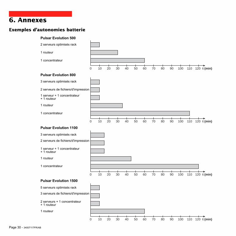
6. AnnexesExemples d'autonomies batterie
Pulsar Evolution 500
Pulsar Evolution 800
Pulsar Evolution 1100
2 serveurs optimisés rack
1 routeur
1 concentrateur
3 serveurs optimisés rack
2 serveurs de fichiers/d'impression
1 routeur
Pulsar Evolution 1500
5 serveurs optimisés rack
3 serveurs de fichiers/d'impression
1 concentrateur
1 serveur + 1 concentrateur+ 1 routeur
3 serveurs optimisés rack
2 serveurs de fichiers/d'impression
1 routeur
1 concentrateur
1 serveur + 1 concentrateur+ 1 routeur
2 serveurs + 1 concentrateur+ 1 routeur
1 routeur
0 10 20 50 100 t (min)30 40 60 70 80 90 110 120
0 10 20 50 100 t (min)30 40 60 70 80 90 110 120
0 10 20 50 100 t (min)30 40 60 70 80 90 110 120
0 10 20 50 100 t (min)30 40 60 70 80 90 110 120

34007117FR/AB - Page 31
6. Annexes
6.2 GlossaireASI Alimentation Sans Interruption.
Autonomie Durée de fonctionnement de l'appareil sur batterie en cas d'impossibilité d'utilisation duréseau électrique d'alimentation.
Barregraphe Indicateur de puissance fournie ou d'autonomie batterie sur le panneau de contrôle.
Disjoncteur d'entrée Appareil de protection du réseau électrique contre les défauts de l'ASI.
Equipements Appareils ou dispositifs raccordés en sortie de l'ASI.
Hors tension ASI déconnectée physiquement du réseau électrique d'alimentation.
Mode "booster" Mode de fonctionnement automatique de l'ASI permettant de remonter la tension duréseau électrique, en cas de faiblesse de celle-ci, au-dessus d'une valeur définie parpersonnalisation, et ceci sans décharger la batterie.
Mode "fader" Mode de fonctionnement automatique de l'ASI permettant d'abaisser la tension duréseau électrique, en cas de valeur trop élevée de celle-ci, au-dessous d'une valeurdéfinie par personnalisation, et ceci sans décharger la batterie.
Personnalisation Certaines fonctions de l'ASI peuvent être modifiées par le logiciel "UPS Driver" afin demieux satisfaire vos besoins.
Port de communication RS232 Permet de relier l'ASI à un ordinateur via le port de communication série.
Port de communication USB Permet de relier l'ASI à un ordinateur via le port de communication USB.
Prises de sortie Pulsar Evolution comporte un groupe de 2 prises de sortie non programmables.
Prises programmables Pulsar Evolution comporte 2 prises programmables. Elles permettent ledémarrage séquentiel des équipements protégés, le délestage d'applications nonprioritaires en mode batterie, ou encore la gestion des priorités en fin d'autonomiebatterie pour conserver la plus longue autonomie aux équipements les plus sensibles.La programmation de ces prises se fait à l'aide du logiciel Solution-Pac contenu dans leCD ROM livré avec l'appareil.
Solution-Pac Suite de logiciels d'administration, de personnalisation et de sécurité MGE UPSSYSTEMS contenue dans le CD ROM livré avec l'appareil.
UPS Driver Logiciel de communication contenu dans le CD ROM livré avec l'appareil et permettantde le personnaliser différemment de la configuration usine.

Page 32 - 34007117FR/AB
6. Annexes
6.3 IndexAArrêt ASI par logiciel ...................................................... 20Autonomie batterie ......................................................... 30
BBarregraphe ..................................................................... 9Batterie
Défaut ....................................................................... 9Fin d'autonomie batterie ......................................... 19Passage sur batterie .......................................... 9, 19Recyclage ............................................................... 27Seuil d'alarme de fin d'autonomie .......................... 19Remplacement ............................................. 22-23-24
Boutons ............................................................................ 9Buzzer ............................................................................ 19
CCarte de communication ............................................ 8, 17Caractéristiques techniques ........................................... 29
DDéfaut ASI ........................................................................ 9Démarrage automatique ................................................ 20Disjoncteur
Batterie ..................................................................... 8D'entrée .................................................................... 8
Dimensions ...................................................................... 7
EEnvironnement ............................................................... 27
MMise en marche ............................................................. 18Mise en veille ................................................................. 20
Démarrage automatique ......................................... 20Mode "booster" .......................................................... 9, 18Mode "fader" .............................................................. 9, 18
PPersonnalisation ........................................................... 20
Batterie .................................................................. 20Conditions On/Off .................................................. 20Sortie ...................................................................... 21
Poids ............................................................................... 7Port de communication RS232 ................................. 8, 16Port de communication USB ..................................... 8, 16Prises programmables ................................................ 8, 9
RRaccordements
Port de communication RS232 .............................. 16Port de communication USB .................................. 16Ligne de données .................................................. 16
Remplacement des batteries ............................ 22, 23, 24
SSécurité .......................................................................... 23Site web ........................................................................ 27Surcharge ..................................................................9, 22
TTempérature ambiante excessive .................................. 29
UUPS Driver .................................................. 18, 19, 20, 29
VVeille ............................................................................. 20Voyants ............................................................................ 9

34007117DE/AB - Seite 1
Installations- undBedienungsanleitung
www.mgeups.com
NO
TH
IN
G
WI
LL
ST
OP
YO
UN O W
MGE UPS SYSTEMS
Pulsar Evolution1500 /1500 Rack1100 /1100 Rack800 /800 Rack
500 Rack

Seite 2 - 34007117DE/AB

34007117DE/AB - Seite 3
Einleitung
Wir danken Ihnen, daß Sie sich für ein Produkt von MGE UPS SYSTEMS zur sicheren Stromversorgung Ihrer Systemeentschieden haben.
Die Baureihe Pulsar Evolution wurde mit größter Sorgfalt entwickelt.Um die Leistungen Ihrer USV (Unterbrechungsfreien Stromversorgung) optimal nutzen zu können, empfehlen wir Ihnen,sich ein wenig Zeit zu nehmen und die vorliegende Anleitung aufmerksam zu lesen.
Für MGE UPS SYSTEMS ist Umweltschutz ein wichtiger Aspekt bei der Entwicklung und Herstellung seiner Produkte.Die ökologische Gesamtkonzeption sowie der konsequente Einsatz der erforderlichen Mittel machen Pulsar Evolution zueinem beispielhaften Produkt in punkto Umweltfreundlichkeit. Es zeichnet sich besonders aus durch :◗ den ökologischen Ansatz in allen Phasen der Produktentwicklung,◗ das Recycling von Pulsar Evolution nach Ablauf der Lebensdauer.
Entdecken Sie das umfassende Angebot von MGE UPS SYSTEMS sowie weitere Optionen zur Baureihe PulsarEvolution auf unseren WEB-Sites www.mgeups.com und www.mgeups.de, oder wenden Sie sich persönlich an denVertreter von MGE UPS SYSTEMS in Ihrer Nähe.
Achtung: Vor Installation und Inbetriebnahme der USV Sicherheitshinweise lesen! (Anleitung Nr. 3400722200).

Seite 4 - 34007117DE/AB
Vorbemerkungen
Aufbau der Installations- und Bedienungsanleitung
WICHTIG, Hinweise unbedingt befolgen.
Informationen, Ratschläge, Hilfen.
Optische Anzeige.
Maßnahmen, Handlungen.
Akustischer Alarm.
In den Abbildungen der nachfolgenden Seiten sind die LED-Anzeigen mit folgenden Symbolen dargestellt:
LED AUS.
LED AN.
LED blinkt.
Die Suche nach bestimmten Informationen erfolgt auf einfachste Weise:◗ über das Inhaltsverzeichnis,◗ über das Stichwortregister.
Bedeutung der Piktogramme

34007117DE/AB - Seite 5
Inhalt
1. Ansichten und Beschreibung1.1 Gesamtansicht ............................................................................................................................ 7
Tower- Modell .................................................................................................................................. 7
Rack- Modell ................................................................................................................................... 7
1.2 Rückansicht ................................................................................................................................. 8
1.3 Anzeige- und Bedienfeld .............................................................................................................. 9
2. Aufstellung und Installation2.1 Entfernen der Verpackung und Überprüfung des Lieferumfangs .......................................... 10
Tower- Modell ................................................................................................................................ 10
Rack- Modell ................................................................................................................................. 11
2.2 Aufstellung .................................................................................................................................. 12
Tower- Modell ................................................................................................................................ 12
Rack- Modell 800/1100/1500 ........................................................................................................ 13
Rack- Modell 500 .......................................................................................................................... 14
2.3 Anschluß der Verbraucher ......................................................................................................... 15
2.4 Anschluß des Kommunikationskabels für RS232- bzw. USB-Schnittstelle (wahlweise) ...... 16
2.5 Anschluß der Verbindung für Datenleitungsschutz (wahlweise) ............................................ 16
2.6 Einbau einer Kommunikationskarte (Option) ............................................................................ 17
3. Betriebszustände3.1 Inbetriebnahme ........................................................................................................................... 18
3.2 Booster- bzw. Fader-Modus (Ausgleich von Netzspannungsschwankungen) ........................... 18
3.3 Batteriebetrieb (bei Netzausfall) .................................................................................................. 19
Umschaltung auf Batteriebetrieb ................................................................................................... 19
Voralarm "Ende der Autonomiezeit" .............................................................................................. 19
3.4 Kundenspezifische Anpassung per Software (wahlweise) ...................................................... 20
Software, Installation und Funktion ............................................................................................... 20
Registerkarte "Ein/Aus-Bedingungen" .......................................................................................... 20
Registerkarte "Batterie" ................................................................................................................. 20
Registerkarte "Spannungsgrenzwerte" ......................................................................................... 21
Registerkarte "Ansprechempfindlichkeit" ...................................................................................... 21

Seite 6 - 34007117DE/AB
Sommaire
4. Wartung und Service4.1 Fehlerbehebung .......................................................................................................................... 22
4.2 Austausch des Batteriemoduls ................................................................................................. 23
Tower- Modell ................................................................................................................................ 23
Rack- Modell ................................................................................................................................. 25
5. Umgebungsbedingungen ........................................................................................................... 27
6. Anhang6.1 Technische Daten ....................................................................................................................... 28
Blockschaltbild .............................................................................................................................. 26
Kenndaten ..................................................................................................................................... 29
Beispiele für Batterie-Autonomiezeiten ......................................................................................... 30
6.2 Fachbegriffe ................................................................................................................................ 31
6.3 Stichwortregister ........................................................................................................................ 32

34007117DE/AB - Seite 7
1. Ansichten und Beschreibung
1.1 GesamtansichtTower- Modell
Rack- Modell
Evolution 800
Evolution 1100
Evolution 1500
Gewicht in kg
10,5
11,5
15
Evolution 500 Rack
Evolution 800 Rack
Evolution 1100 Rack
Evolution 1500 Rack
Evolution 500 Rack
Evolution 800 Rack
Evolution 1100 Rack
Evolution 1500 Rack
Abmessungen in mm(B x H x T)
438 x 43,5 x 353
438 x 43,5 x 499
438 x 43,5 x 499
438 x 43,5 x 522(19") (1U)
Gewicht in kg
9
15,5
16
19
Evolution 800
Evolution 1100
Evolution 1500
Abmessungen in mm(B x H x T)
150 x 237 x 415
150 x 237 x 415
150 x 237 x 483
P U L S A R
Evolution
1 1 0 0
B
H
T
B
H
T
P U L S A R
Evolution
1500 Rack

Seite 8 - 34007117DE/AB
1. Ansichten und Beschreibung
1.2 Rückansicht
Pulsar Evolution 500 / 800 / 1100 Rack
USB-Schnittstelle.
RS232-Schnittstelle.
Datenleitungsschutz.
Steckplatz für Kommunikationskarte(Option).
2 normale (nicht programmierbare)Ausgangssteckdosen.
2 programmierbareAusgangssteckdosen (1 und 2).
Eingangsschalter.
Netzanschluß.
1
2
3
4
5
6
7
8
1238 45
1 2
Pulsar Evolution 800 / 1100 / 1500
1
2
3
4
6
5
2
1
Pulsar Evolution 1500 Rack
8
6
12 384 5
1 2
6
7
7
7
Pulsar Evolution 1500 :

34007117DE/AB - Seite 9
1 2
%%
1.3 Anzeige- und Bedienfeld
Balkenanzeige Auslastungsgrad.
Programmierbare Steckdosengruppe 1 an Spannung.
EIN/AUS-Taster (ON/OFF) mit LED zur Freischaltung/Trennung derAusgangssteckdosen.
Programmierbare Steckdosengruppe 2 an Spannung.
Batteriebetrieb.
10
11
12
15
14
18
17
13
16
1. Ansichten und Beschreibung
USV-Störung.
Batteriestörung.
Überlast.
Booster- oder Fader-Modus.
Balkenanzeige Batterieladezustand.
0 bis 25%.
26 bis 50%.
51 bis 75%.
76 bis 100%.

Seite 10 - 34007117DE/AB
2. Aufstellung und Installation
2.1 Entfernen der Verpackung und Überprüfung des Lieferumfangs
2 Verbraucher-Anschlußkabel.
RS232-Schnittstellenkabel.
USB-Schnittstellenkabel.
CD ROM mit USV-Software "Solution Pac" und "UPS Driver".
Dokumentation.
23
21
20
21
22
23
24
2220
24
30
Tower- Modell
P U L S A R
Evolution
1 1 0 0

34007117DE/AB - Seite 11
2. Aufstellung und Installation
2 Verbraucher-Anschlußkabel.
RS232-Schnittstellenkabel.
USB-Schnittstellenkabel.
CD ROM mit USV-Software "Solution Pac" und "UPS Driver".
Dokumentation.
Montagekit für Einbau in 19"-Schränke.
Verriegelungsabdeckung für Verbraucher-Anschlußkabel.
20
21
22
23
24
25
26
26
21 2220
2423 25
Rack- Modell
P U L S A R
Evolut ion
1500 Rack

Seite 12 - 34007117DE/AB
2. Aufstellung und Installation
2.2 AufstellungTower- Modell
P U L S A
R
Evolutio
n
1 1 0 0
P U L S A R
Evolution
1 1 0 0

34007117DE/AB - Seite 13
2. Aufstellung und Installation
Montage und Befestigung der Teleskopschienen für Rackeinbau (Schritte 1 bis 6 befolgen)
Befestigungsschrauben und Teleskopschienen liegen dem Gerät bei.
12
22
2
53
6
6
5
4
3
Rack- Modell 800/1100/1500
P U L S A R
Evolution
1500 Rack

Seite 14 - 34007117DE/AB
2. Aufstellung und InstallationRack- Modell 500
1
2
3
3
1
P U L S A R
Evolution
1500 Rack
P U L S A R
Evolution
1500 Rack
P U L S A R
Evolution
1500 Rack

34007117DE/AB - Seite 15
2.3 Anschluß der Verbraucher
Kenndaten auf dem Typenschild (siehe Geräte-Rückseite) hinsichtlich Übereinstimmung mit den vorhandenenNetzparametern und der Leistungsaufnahme aller angeschlossenen Verbraucher überprüfen.
1 - Netzkabel der Verbraucher abziehen.
2 - Abgezogenes Verbraucher-Netzkabel(1)
in die Gerätesteckdose 8 der USV unddann in die Netzsteckdose einstecken.
3 - Verbraucher mit Hilfe der Anschlußkabel␣ 20 an die USV anschließen.Verbraucher höherer Priorität solltenvorzugsweise an die beiden Steckdosen 5und weniger wichtige Verbraucher an diebeiden programmierbaren Steckdosen 6angeschlossen werden.
Um den Abwurf der Steckdosen 6im Batterietrieb zu programmierenund so die Nutzung derAutonomiereserve zu optimieren,wird die mitgelieferte USV-Software benötigt.
4 - Verriegelungsabdeckung 26 mit Hilfeder Befestigungsschrauben anbringen (nurRack-Modelle).
5
6
2. Aufstellung und Installation
8
Nach dem erstmaligen Netzanschluß der USV benötigt das Gerät eine Ladezeit von mindestens 8 Stunden, um dievolle Autonomiezeit der Batterie zur Verfügung zu stellen.
(1) Kenndaten des Anschlußkabels überprüfen(Mindestens 250 V - 10 A, Querschnitt 1 mm2 TypHO5).
20
2
1
Die nachstehenden Abbildungen zur Illustration der Informationen zeigen das Tower-Modell einer Pulsar Evolution 1500.Alle Hinweise gelten sinngemäß auch für die übrigen Tower- und Rack-Modelle.

Seite 16 - 34007117DE/AB
RS232
2. Aufstellung und Installation
2.4 Anschluß des Kommunikationskabels für RS232- bzw. USB-Schnittstelle (wahlweise)
1 - RS232- 21 oder USB-Kabel 22 an dieserielle Schnittstelle bzw. den USB-Port deszu schützenden Systems anschließen.
2 - Kabel 21 bzw. 22 mit dem anderenEnde an die RS232-Schnittstelle 2 oderden USB-Port 1 der USV anschließen.
Die USV kann nun über verschiedeneSoftwarepakete von MGE UPS SYSTEMSmit dem angeschlossenen Rechnersystemkommunizieren (Überwachung,Konfiguration, Sicherheitsparameter).
21
22
RS232- und USB-Schnittstellekönnen nicht gleichzeitigverwendet werden.
2.5 Anschluß der Verbindung für Datenleitungsschutz (wahlweise)Mit Hilfe der USV-Funktion"Datenleitungsschutz" könnenÜberspannungen in den Datenleitungen desEDV-Systems verhindert werden.Hierzu ist die zu schützende Datenleitunggemäß nebenstehender Abbildung an dieSteckbuchsen "Data line protection" IN/OUTanzuschließen (RJ45-Kabel (OUT) nicht imLieferumfang).
1
2
IN OUT
RS232
DATA LINEPROTECTION
Die nachstehenden Abbildungen zur Illustration der Informationen zeigen das Tower-Modell einer Pulsar Evolution 1500.Alle Hinweise gelten sinngemäß auch für die übrigen Tower- und Rack-Modelle.

34007117DE/AB - Seite 17
2. Aufstellung und Installation
2.6 Einbau einer Kommunikationskarte (Option)
1 - Abdeckung 4 durch Herausdrehen derzwei Schrauben von der USV lösen.
2 - Karte in den Steckplatz einstecken.
3 - Karte mit den zwei Schraubenbefestigen.
Steckplatz fürKommunikationskarte(beschränkter Zugang).
4
Die Kommunikationskarten können bei eingeschalteter USV installiert werden.Der Einbau darf nur durch Fachpersonal erfolgen.
IN OUTDATA LINE PROTECTION
RS232

Seite 18 - 34007117DE/AB
1 2
%%
3. Betriebszustände
3.1 Inbetriebnahme
10
11
12
EIN/AUS-Taste 10 drücken.Der Summer ertönt kurz, und sämtliche LEDs leuchten gleichzeitig auf.Während des anschließenden Selbstests ertönt der Summer zweimal.Die LED der Drucktaste 10 leuchtet kontinuierlich und zeigt an, daß dieAusgangssteckdosen versorgt werden.- Einspeisenetz vorhanden: Nur die LED der EIN/AUS-Taste 10leuchtet. Die Verbraucherversorgung erfolgt aus dem Einspeisenetz.- Einspeisenetz nicht vorhanden: Die LED der EIN/AUS-Taste 10und die LED 16 leuchten. Die Verbraucherversorgung erfolgt aus derBatterie über den Wechselrichter der USV.
Alle angeschlossenen Verbraucher werden versorgt.
1 2
%%
3.2 Booster- bzw. Fader-Modus(Ausgleich von Netzspannungsschwankungen)
16
Die Booster- bzw. Fader-Funktion der USV ermöglicht es, dieAusgangsspannung innerhalb eines definierten Toleranzbereichs zuhalten. Dabei werden größere Netzspannungsschwankungen ohneInanspruchnahme der Batterie durch entsprechendes Anheben bzw.Absenken der Ausgangsspannung ausgeglichen.Die Grenzwerte dieses Bereichs können über die USV-Software "UPSDriver" festgelegt werden.Während des Betriebs der USV im Booster- bzw. Fader-Modus leuchtetdie LED 16 auf und zeigt eine entsprechendeNetzspannungsabweichung an.
Bleiben die Anzeigen 10 oder 11 erloschen, oder leuchtet LED 12 auf, liegt eine Störung vor (siehe Abschnitt 4.1).Hinweis: Die Aufladung der Batterie beginnt sofort nach dem Netzanschluß der USV, selbst wenn die EIN/AUS-Taste 10noch nicht betätigt wurde.

34007117DE/AB - Seite 19
1 2
%%
1 2
%%
3. Betriebszustände
3.3 Batteriebetrieb (bei Netzausfall)Umschaltung auf Batteriebetrieb
Verläßt das Einspeisenetz den zulässigen Toleranzbereich, schaltet dieUSV auf Batteriebetrieb und die LED 11 leuchtet auf.Während des Batteriebetriebs ertönt alle 10 Sekunden ein akustischesSignal.
Die an die USV angeschlossenen Verbraucher werdenunterbrechungsfrei über die Batterie weiter versorgt.
Voralarm "Ende der Autonomiezeit"Wird dieser Grenzwert erreicht, ertönt der Summer alle 3 Sekunden.Dieser Alarmgrenzwert kann über die Software "UPS Driver"kundenspezifisch angepaßt werden.
Die Batterie ist kurz vor dem Entladeende. Es sollten alleAnwendungen geschlossen werden, da die Abschaltung der USVkurz bevorsteht.
Erreicht die Batterie das Ende ihrer Autonomiezeit, schaltet die USV abund alle LEDs erlöschen.
Die Verbraucher werden NICHT mehr versorgt.
11
Bei Rückkehr des Einspeisenetzes schaltet sich die USV automatisch wieder ein.Ist dies nicht der Fall, ist zu überprüfen, ob die Funktion "Automatischer Neustart" deaktiviert wurde (siehe Abschnitt 3.4"Kundenspezifische Anpassung per Software").
11

Seite 20 - 34007117DE/AB
3. Betriebszustände
3.4 Kundenspezifische Anpassung per Software (wahlweise)
Software, Installation und Funktion
Einstellungen
Automatischer Neustart
Kaltstart über Batterie
Zwangsabschaltung
Sleep-Modus
USV-Start/Stop über Software
Default-Einstellung
Aktiviert
Aktiviert
Aktiviert
Deaktiviert
Aktiviert
Die kundenspezifische Anpassung der USV kann mit Hilfe der Software "UPS Driver" über einen Rechner erfolgen, derüber die serielle RS232-Schnittstelle mit der USV verbunden ist (siehe Abschnitt 2.4).
Vorhandensein der RS232- 21 Verbindung überprüfen.
Installation der Software "UPS Driver":
1. CD-ROM "Solution Pac" in das Laufwerk des PCs (mit Windows-Betriebssystem) einlegen.2. Windows-Dateimanager bzw. -Explorer öffnen und CD-ROM-Laufwerk auswählen.3. Doppelklicken auf die Datei Setup.exe im Verzeichnis "\Emb\Evolutio\Config\".
Nach Installation der Software "UPS Driver" stehen folgende Einstellungsmöglichkeiten zur Verfügung:
Registerkarte "Batterie"
Einstellungen
Zeitintervall für automatischen Batterietest
Grenzwert Voralarm "Ende der Autonomiezeit"
Tiefentladungsschutz
Default-Einstellung
Einmal pro Woche
20% Restautonomiezeit
Aktiviert
Kundenspezifische Anpassung
Einmal pro TagEinmal pro Monat
Kein Test
10 bis 40% Restautonomiezeit
Deaktiviert
Kundenspezifische Anpassung
Deaktiviert
Deaktiviert
Deaktiviert
Aktiviert
Deaktiviert
Registerkarte "Ein/Aus-Bedingungen"

34007117DE/AB - Seite 21
3. Betriebszustände
Einstellungen
Ansprechempfindlichkeit der USV
Default-Einstellung
Normal
Kundenspezifische Anpassung
Hoch oder niedrig
Registerkarte "Spannungsgrenzwerte"
Registerkarte "Ansprechempfindlichkeit"
Nähere Informationen zu den Kennwerten können den Hilfetexten der Software "UPS Driver" entnommen werden.
(1) Unterer Spannungsgrenzwert für Umschaltung auf Batterie = 150 V
Einstellungen
Ausgangsspannung (Batteriebetrieb)
Oberer Spannungsgrenzwert fürUmschaltung auf Batterie
Grenzwert für Einschaltung des Fader-Modus’
Grenzwert für Einschaltung des Booster-Modus’
Unterer Spannungsgrenzwert fürUmschaltung auf Batterie
Maximaler Eingangsspannungsbereich
Default-Einstellung
230 V
294 V
265 V
184 V
160 V
Deaktiviert
Kundenspezifische Anpassung
200 V - 220 V - 240 V
271 bis 294 V
244 bis 265 V
184 bis 207 V
160 bis 180 V
Aktiviert (1)
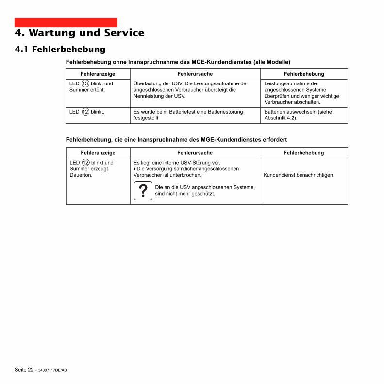
Seite 22 - 34007117DE/AB
Fehlerbehebung, die eine Inanspruchnahme des MGE-Kundendienstes erfordert
4. Wartung und Service
4.1 FehlerbehebungFehlerbehebung ohne Inanspruchnahme des MGE-Kundendienstes (alle Modelle)
Fehleranzeige
LED 13 blinkt undSummer ertönt.
LED 12 blinkt.
Fehlerursache
Überlastung der USV. Die Leistungsaufnahme derangeschlossenen Verbraucher übersteigt dieNennleistung der USV.
Es wurde beim Batterietest eine Batteriestörungfestgestellt.
Fehlerbehebung
Leistungsaufnahme derangeschlossenen Systemeüberprüfen und weniger wichtigeVerbraucher abschalten.
Batterien auswechseln (sieheAbschnitt 4.2).
Fehleranzeige
LED 12 blinkt undSummer erzeugtDauerton.
Fehlerursache
Es liegt eine interne USV-Störung vor.◗ Die Versorgung sämtlicher angeschlossenenVerbraucher ist unterbrochen.
Die an die USV angeschlossenen Systeme sind nicht mehr geschützt.
Fehlerbehebung
Kundendienst benachrichtigen.

34007117DE/AB - Seite 23
P U L S A R
Evolution
1 5 0 0
B
A
C
4.2 Austausch des Batteriemoduls
4. Wartung und Service
Ausbau des BatteriemodulsDie Batterien können bei eingeschalteter USV ausgetauscht werden.
Sicherheitsmaßnahmen:Die Batterie hat einen hohen Kurzschlußstrom und kann Stromschläge verursachen.Bei jeder Handhabung der Batterien sind daher folgende Sicherheitsmaßnahmen einzuhalten:◗ Armbanduhren, Ringe, Armreifen und sonstige an Händen oder Armen getragene Metallgegenstände abnehmen.◗ Werkzeuge mit Isoliergriff verwenden.
A - An der Frontseite den Schildträger mitdem MGE-Logo herausdrücken. B - Die beiden dahinter liegendenSchrauben lösen. C - Linken Teil der Frontabdeckung leichtanheben nach vorn abziehen.
Tower- Modell
D
D - Batteriemodul durch Lösen derSteckverbindung (niemals an denVerbindungskabeln ziehen!) abklemmen.

Seite 24 - 34007117DE/AB
4. Wartung und Service
Einbau des neuen BatteriemodulsDie oben beschriebenen Handgriffe in umgekehrter Reihenfolge ausführen.
◗ Achtung! Beim Einschieben der neuen Batterie kann es zur Lichtbogenbildung zwischen den Kontaktenkommen.◗ Zur Gewährleistung der Sicherheit und des Betriebsverhaltens dürfen nur Austauschmodule verwendet werden,die mit den eingebauten Batterien baugleich sind.◗ Es ist sicherzustellen, daß der Batteriestecker vollständig in die zugehörige Steckbuchse eingesteckt ist.
E - Batteriemodul durch Greifen derKunststofflasche herausziehen und durchneues ersetzen.
E

34007117DE/AB - Seite 25
D
A
BC
P U L S A R
Evolution
1 5 0 0
4. Maintenance
Ausbau des BatteriemodulsDie Batterien können bei eingeschalteter USV ausgetauscht werden.
A - An der Frontseite den Schildträger mitdem MGE-Logo herausdrücken. B - Die beiden dahinter liegendenSchrauben lösen. C - Linken Teil der Frontabdeckung nachvorn abziehen.
D - Batteriemodul durch Lösen derSteckverbindung (niemals an denVerbindungskabeln ziehen!) abklemmen.
Rack- Modell
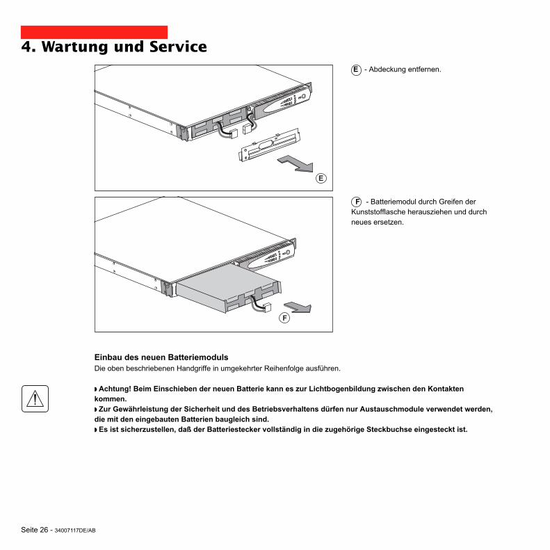
Seite 26 - 34007117DE/AB
F
E
4. Wartung und Service
Einbau des neuen BatteriemodulsDie oben beschriebenen Handgriffe in umgekehrter Reihenfolge ausführen.
◗ Achtung! Beim Einschieben der neuen Batterie kann es zur Lichtbogenbildung zwischen den Kontaktenkommen.◗ Zur Gewährleistung der Sicherheit und des Betriebsverhaltens dürfen nur Austauschmodule verwendet werden,die mit den eingebauten Batterien baugleich sind.◗ Es ist sicherzustellen, daß der Batteriestecker vollständig in die zugehörige Steckbuchse eingesteckt ist.
E - Abdeckung entfernen.
F - Batteriemodul durch Greifen derKunststofflasche herausziehen und durchneues ersetzen.

34007117DE/AB - Seite 27
5. UmweltschutzBei der Entwicklung des vorliegenden Produkts wurde besonders auf seine Umweltverträglichkeit
geachtet:
Es enthält weder FKW- noch FCKW-Verbindungen.
Recycling der USV nach Ablauf der Lebensdauer:
MGE UPS SYSTEMS verpflichtet sich, sämtliche nach Ablauf der Lebensdauer rückgeführten Komponenten durchzugelassene Entsorgungsunternehmen einer Wiederverwertung gemäß den gesetzlichen Bestimmungen zuzuführen(wenden Sie sich bitte an Ihre MGE-Vertretung).
Verpackung:
Verpackungsmaterial muß gemäß den gesetzlichen Bestimmungen entsorgt werden.
Hinweis:
Dieses Produkt enthält Bleibatterien. Blei kann die Umwelt schädigen, wenn es nicht gemäß den gesetzlichen Vorschriftendurch Spezialunternehmen entsorgt wird.
Web-Site: www.mgeups.com

Seite 28 - 34007117DE/AB
6. Anhang
6.1 Technische DatenBlockschaltbild
Netz
Verbraucher
Batterie
Gleichrichter/Ladegerät
Wechselrichter
Booster-/Fader-TrafoFilter

34007117DE/AB - Seite 29
6. AnhangKenndaten
Ausgangsleistung
Einspeisenetz◗ Spannung◗ Frequenz
USV-Ausgang(Batteriebetrieb)◗ Spannung◗ Frequenz
Batterie (wartungsfreieBleiakkus)◗ Tower- Modell◗ Rack- Modell
Umgebungsbedingungen◗ Geräuschpegel(Netzbetrieb)◗ zul. Betriebstemperatur◗ relative Luftfeuchtigkeit(ohne Kondensation)
500
500 VA / 350 W
2 x 6 V - 9 Ah,
1100 / 1100 Rack
1100 VA / 700 W
2 x 12 V - 9 Ah,4 x 6 V - 9 Ah
(1) Oberer und unterer Grenzwert über Software "UPS Driver" einstellbar.(2) Bis 40 Hz bei niedriger Ansprechempfindlichkeit der USV (einstellbar über USV-Software "UPS Driver").(3) Einstellbar zwischen 200 und 240 V über USV-Software "UPS Driver".
800 / 800 Rack
800 VA / 560 W
2 x 12 V - 7,2 Ah,4 x 6 V - 7,2 Ah
1500 / 1500 Rack
1500 VA / 1000 W
3 x 12 V - 9 Ah,6 x 6 V - 9 Ah
Pulsar Evolution
160 bis 294 V (1), einphasig, Un = 230 V
230 V (3) (+6% / - 10%), einphasig50/60 Hz +/- 0,1 Hz
<40 dBA
0 bis 35° C20 bis 90%
<40 dBA
0 bis 40° C20 bis 90%
47 - 70 Hz (50-Hz-Netz) bzw. 56,5 - 70 Hz (2) (60-Hz-Netz)

Seite 30 - 34007117DE/AB
6. AnhangBeispiele für Batterie-Autonomiezeiten
Pulsar Evolution 500
Pulsar Evolution 800
Pulsar Evolution 1100
1 Router
Pulsar Evolution 1500
2 optimierte Rack-Server
2 Print-Server
1 Hub
1 Server + 1 Router + 1 Hub
0 10 20 50 100 t (min)30 40 60 70 80 90 110 120
0 10 20 50 100 t (min)30 40 60 70 80 90 110 120
1 Router
3 optimierte Rack-Server
1 Hub
2 Print-Server
1 Server + 1 Router + 1 Hub
1 Router
3 optimierte Rack-Server
1 Hub
5 optimierte Rack-Server
3 Print-Server
2 Server + 1 Router + 1 Hub
1 Router
0 10 20 50 100 t (min)30 40 60 70 80 90 110 120
0 10 20 50 100 t (min)30 40 60 70 80 90 110 120

34007117DE/AB - Seite 31
6. Anhang
6.2 FachbegriffeAusgangssteckdosen Pulsar Evolution verfügt abgangsseitig über eine Gruppe von 2 nicht
programmierbaren Ausgangssteckdosen.
Autonomiezeit Betriebsdauer des Geräts mit Verbraucherversorgung über die Batterie bei Ausfall desEinspeisenetzes.
Balkenanzeige LED-Leiste am Bedienfeld zur Anzeige des Auslastungsgrads und derRestautonomiezeit.
Booster-Modus Automatische Betriebsart der USV, mit deren Hilfe eine zu geringe Netzspannung ohneInanspruchnahme der Batterie um einen einstellbaren Wert angehoben werden kann.
Eingangsschalter Schalter zum Schutz des Einspeisenetzes gegen Störungen der USV-Anlage.
Fader-Modus Automatische Betriebsart der USV, mit deren Hilfe eine zu hohe Netzspannung ohneInanspruchnahme der Batterie um einen einstellbaren Wert abgesenkt werden kann.
Kundenspezifische Bestimmte USV-Funktionen können über die Software "UPS Driver" an individuelleAnpassung Kundenbedürfnisse angepaßt werden.
Programmierbare Pulsar Evolution verfügt abgangsseitig über eine Gruppe von 2 programmierbarenSteckdosen Ausgangssteckdosen. Sie ermöglichen eine sequentielle Aufschaltung der geschützten
Verbraucher und den Abwurf im Batteriebetrieb, um die Versorgung der kritischstenVerbraucher am längsten aufrechterhalten zu können. Die Programmierung erfolgt überdie USV-Software "Solution Pac" (mitgelieferte CD-ROM).
RS232-Schnittstelle Serielle Schnittstelle zur Herstellung einer Kommunikationsverbindung zwischen USVund geschütztem Rechnersystem.
Solution-Pac USV-Software zur kundenspezifischen Anpassung von Überwachungs-, Konfigurations-und Sicherheitsparametern. CD-ROM im Lieferumfang der USV-Anlage.
Spannungsfreischaltung Physikalische Trennung der USV vom Einspeisenetz.der USV
UPS Driver Kommunikationssoftware zur kundenspezifischen Anpassung von USV-Einstellungen.Auf CD-ROM "Solution-Pac" enthalten.
USB-Schnittstelle Schnittstelle zur Herstellung einer Kommunikationsverbindung zwischen USV undgeschütztem Rechnersystem.
USV Unterbrechungsfreie Stromversorgung.

Seite 32 - 34007117DE/AB
6. Anhang
6.3 StichwortregisterAAbmessungen und Gewichte ........................................... 7Alarmton (Summer) ........................................................ 19Anschlüsse
Datenleitung ...........................................................16RS232-Schnittstelle ................................................16USB-Schnittstelle .................................................. 16
Ausschalten der USV über Software ............................. 20Austausch des Batteriemoduls ......................... 22, 23, 24Automatischer Neustart ................................................. 20
BBalkenanzeige ................................................................. 9Batterie-Autonomiezeiten ............................................... 30Batterie
Austausch ..................................................... 22-23-24Abschaltung am Ende der Autonomiezeit .............. 19Recycling ................................................................ 27Störung ..................................................................... 9Umschaltung auf Batteriebetrieb ........................ 9, 19Voralarm "Ende der Autonomiezeit" ....................... 19
Booster-Modus ........................................................... 9, 18
DDrucktasten ...................................................................... 9
FFader-Modus .............................................................. 9, 18
GGewicht ............................................................................ 7
IInbetriebnahme .............................................................. 18
KKenndaten ...................................................................... 29Kommunikationskarte ................................................ 8, 17Kundenspezifische Anpassung ..................................... 20
Ausgang ................................................................. 21Batterie .................................................................. 20Ein/Aus-Bedingungen ............................................. 20
LLeistungsschalter
Batterieschalter ........................................................ 8Eingangsschalter ...................................................... 8
Leuchtanzeigen ................................................................ 9
PProgrammierbare Steckdosen ..................................... 8, 9
RRS232-Schnittstelle .................................................. 8, 16
SSicherheit ...................................................................... 23Sleep-Modus .................................................................. 20
Automatischer Neustart .......................................... 20Störung der USV .............................................................. 9
UÜberlast ...................................................................... 9, 22Umgebungstemperatur zu hoch ..................................... 29Umweltschutz ................................................................. 27UPS Driver .................................................. 18, 19, 20, 29USB-Schnittstelle ....................................................... 8, 16
WWeb Site ........................................................................ 27

34007117IT/AB - Pagina 1
Manualed’installazione perl’utente
www.mgeups.com
NO
TH
IN
G
WI
LL
ST
OP
YO
UN O W
MGE UPS SYSTEMS
Pulsar Evolution1500 /1500 Rack1100 /1100 Rack800 /800 Rack
500 Rack

Pagina 2 - 34007117IT/AB

34007117IT/AB - Pagina 3
Introduzione
Vi ringraziamo di aver scelto un prodotto MGE UPS SYSTEMS per la sicurezza delle vostre apparecchiature.
La gamma Pulsar Evolution è stata studiata con notevole cura per i singoli dettagli.Per usufruire al meglio delle prestazioni della vostra unità UPS (gruppo statico di continuità), vi consigliamo di dedicare deltempo alla lettura del presente manuale.
MGE UPS SYSTEMS presta una particolare attenzione all’impatto dei suoi prodotti sull’ambiente.Le importanti risorse impiegate fanno di Pulsar Evolution un punto di riferimento in materia di protezione ambientale, inparticolare per quanto riguarda:◗ L’approccio di ecoprogettazione nel corso del processo di sviluppo,◗ Il riciclaggio di Pulsar Evolution al termine del ciclo di vita del prodotto.
Vi invitiamo a scoprire l’offerta MGE UPS SYSTEMS, nonché le opzioni della gamma Pulsar Evolution visitando il nostrosito WEB all’indirizzo www.mgeups.it oppure contattando il vostro rappresentante MGE UPS SYSTEMS.
Importante: prima dell’installazione e dell’uso dell’UPS, è tassativo leggere attentamente le istruzioni di sicurezza fornite(documento n° 3400722200).

Pagina 4 - 34007117IT/AB
Premessa
Struttura della documentazione
Seguire tassativamente queste istruzioni.
Informazioni, consigli, aiuto.
Segnalazione visiva.
Azione.
Segnalazione acustica.
Le convenzioni adottate per rappresentare le spie all’interno delle illustrazioni sono le seguenti:
Spia spenta.
Spia accesa.
Spia lampeggiante.
La ricerca di informazioni si esegue principalmente in due modi:◗ Tramite il sommario.◗ Tramite l’indice analitico.
Convenzioni dei pittogrammi

34007117IT/AB - Pagina 5
Sommario
1. Presentazione1.1 Viste generali ............................................................................................................................... 7
Modelli "tower" ................................................................................................................................ 7
Modelli "slot" ................................................................................................................................... 7
1.2 Vista posteriore ........................................................................................................................... 8
1.3 Pannello di controllo .................................................................................................................... 9
2. Installazione2.1 Apertura dell’imballaggio e verifica .......................................................................................... 10
Modelli "tower" .............................................................................................................................. 10
Modelli "slot" ................................................................................................................................. 11
2.2 Installazione ................................................................................................................................ 12
Modelli "tower" .............................................................................................................................. 12
Modelli "slot" 800/1100/1500 ......................................................................................................... 13
Modelli "slot" 500 .......................................................................................................................... 14
2.3 Collegamento delle apparecchiature ........................................................................................ 15
2.4 Collegamento della porta di comunicazione RS232 o USB (facoltativo) ................................ 16
2.5 Collegamento della protezione della linea dati (facoltativo) .................................................... 16
2.6 Installazione dell’opzione "scheda di comunicazione" ........................................................... 17
3. Uso3.1 Avviamento .................................................................................................................................. 18
3.2 Passaggio in modalità "booster" o "fader" (in caso di variazione di tensione della rete) ........ 18
3.3 Alimentazione a batteria (in caso di assenza della rete elettrica) .............................................. 19
Passaggio sulla batteria ................................................................................................................ 19
Soglia di allarme di fine autonomia batteria raggiunta .................................................................. 19
3.4 Personalizzazione (facoltativo) ................................................................................................... 20
Funzione ....................................................................................................................................... 20
Menù "Condizioni On/Off" ............................................................................................................. 20
Menù "Batteria" ............................................................................................................................. 20
Menù "Soglie di tensione" ............................................................................................................. 21
Menù "Sensibilità" ......................................................................................................................... 21

Pagina 6 - 34007117IT/AB
Sommario
4. Manutenzione4.1 Risoluzione avarie ...................................................................................................................... 22
4.2 Sostituzione del modulo batteria .............................................................................................. 23
Modelli "tower" .............................................................................................................................. 23
Modelli "slot" ................................................................................................................................. 25
5. Ambiente .................................................................................................................. 27
6. Allegati6.1 Caratteristiche tecniche ............................................................................................................. 28
Schema sinottico ........................................................................................................................... 26
Caratteristiche tecniche ................................................................................................................ 29
Esempi di autonomia della batteria ............................................................................................... 30
6.2 Glossario ..................................................................................................................................... 31
6.3 Indice analitico ............................................................................................................................ 32

34007117IT/AB - Pagina 7
1. Presentazione
1.1 Viste generaliModelli "tower"
Modelli "slot"
Evolution 800
Evolution 1100
Evolution 1500
Peso in Kg
10,5
11,5
15
Evolution 500 Rack
Evolution 800 Rack
Evolution 1100 Rack
Evolution 1500 Rack
Evolution 500 Rack
Evolution 800 Rack
Evolution 1100 Rack
Evolution 1500 Rack
Dimensioni in mm(L x A x P)
438 x 43,5 x 353
438 x 43,5 x 499
438 x 43,5 x 499
438 x 43,5 x 522(19") (1U)
Peso in Kg
9
15,5
16
19
Evolution 800
Evolution 1100
Evolution 1500
Dimensioni in mm(L x A x P)
150 x 237 x 415
150 x 237 x 415
150 x 237 x 483
P U L S A R
Evolution
1 1 0 0
L
A
P
L
A
P
P U L S A R
Evolution
1500 Rack
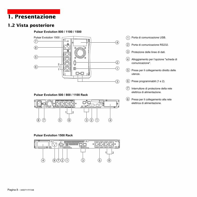
Pagina 8 - 34007117IT/AB
1. Presentazione
1.2 Vista posteriore
Pulsar Evolution 500 / 800 / 1100 Rack
Porta di comunicazione USB.
Porta di comunicazione RS232.
Protezione delle linee di dati.
Alloggiamento per l’opzione "scheda dicomunicazione".
Prese per il collegamento diretto delleutenze.
Prese programmabili (1 e 2).
Interruttore di protezione della reteelettrica di alimentazione.
Presa per il collegamento alla reteelettrica di alimentazione.
1
2
3
4
5
6
7
8
1238 45
1 2
Pulsar Evolution 800 / 1100 / 1500
1
2
3
4
6
5
2
1
Pulsar Evolution 1500 Rack
8
6
12 384 5
1 2
6
7
7
7
Pulsar Evolution 1500 :

34007117IT/AB - Pagina 9
1 2
%%
1.3 Pannello di controllo
Barra dei LED del livello di potenza utilizzata in uscita.
Prese programmabili 1 alimentate.
Pulsante luminoso di Accensione/Spegnimento (ON/OFF) delle prese diuscita.
Prese programmabili 2 alimentate.
Funzionamento a batteria.
10
11
12
15
14
18
17
13
16
1. Presentazione
Difetto dell’apparecchio
Difetto della batteria.
UPS in sovraccarico.
Funzionamento in modalità "booster" o "fader".
Barra dei LED del livello di carica della batteria.
Dallo 0 al 25%.
Dal 26 al 50%.
Dal 51 al 75%.
Dal 76 al 100%.

Pagina 10 - 34007117IT/AB
2. Installazione
2.1 Apertura dell’imballaggio e verifica
2 cavi per collegare le utenze.
Cavo di comunicazione RS 232.
Cavo di comunicazione USB.
CD ROM contenente i software "Solution Pac" e "UPS Driver".
Documentazione.
23
21
20
21
22
23
24
2220
24
30
Modelli "tower"
P U L S A R
Evolution
1 1 0 0

34007117IT/AB - Pagina 11
2. Installazione
2 cavi per collegare le utenze.
Cavo di comunicazione RS 232.
Cavo di comunicazione USB.
CD ROM contenente i software "Solution Pac" e "UPS Driver".
Documentazione.
Kit di montaggio all’interno di un armadio rack 19".
Sistema di fissaggio dei cavi di alimentazione delle utenze.
20
21
22
23
24
25
26
26
21 2220
2423 25
Modelli "slot"
P U L S A R
Evolut ion
1500 Rack

Pagina 12 - 34007117IT/AB
2. Installazione
2.2 InstallazioneModelli "tower"
P U L S A
R
Evolutio
n
1 1 0 0
P U L S A R
Evolution
1 1 0 0

34007117IT/AB - Pagina 13
2. Installazione
Montaggio e fissaggio delle guide e dello slot: seguire le tappe da 1 a 6.
Le viti di fissaggio e le guide sono fornite da MGE UPS SYSTEMS.
12
22
2
53
6
6
5
4
3
Modelli "slot" 800/1100/1500
P U L S A R
Evolution
1500 Rack

Pagina 14 - 34007117IT/AB
2. InstallazioneModelli "slot" 500
1
2
3
3
1
P U L S A R
Evolution
1500 Rack
P U L S A R
Evolution
1500 Rack
P U L S A R
Evolution
1500 Rack

34007117IT/AB - Pagina 15
2.3 Collegamento delle utenze
Verificare che le indicazioni riportate sulla targa di identificazione situata nella parte posteriore dell’apparecchiocorrispondano alla rete elettrica di alimentazione ed ai consumi elettrici reali delle utenze.
1 - Scollegare il cavo di alimentazionedall’apparecchiatura.
2 - Collegare questo cavo(1) alla presa 8 ,poi alla presa della rete elettrica dialimentazione.
3 - Collegare le utenze all’UPS mediante icavi 20 .Collegare preferibilmente le apparecchiatureprioritarie alle 2 prese 5 e leapparecchiature non prioritarie alle 2 preseprogrammabili 6 (1 e 2).
Per poter programmare l’arrestodelle prese 6 in fase diautonomia della batteria edottimizzare così la durata di taleautonomia, è necessario utilizzareil software di comunicazione MGEUPS SYSTEMS.
4 - Chiudere il collegamento fissando ilsistema 26 (solo per i modelli slot).
5
6
2. Installazione
8
Dopo la prima messa sotto tensione, è necessario attendere almeno 8 ore affinché la batteria possa fornirel’autonomia nominale.
(1) Accertarsi che le caratteristiche di questo cavosiano: 250V – 10A (sezione 1mm2, tipo H05).
20
2
1
Le istruzioni di seguito riportate sono illustrate utilizzando un modello Pulsar Evolution 1500 tower. Il principio è identicoper gli altri modelli tower e slot.

Pagina 16 - 34007117IT/AB
RS232
2. Installazione
2.4 Collegamento della porta di comunicazione RS232 o USB (facoltativo)
1 - Collegare il cavo di comunicazione RS232 21 o USB 22 alla porta seriale o USBdell’apparecchiatura informatica.
2 - Collegare l’altra estremità del cavo dicomunicazione 21 o 22 alla porta dicomunicazione RS232 2 o USB 1dell’UPS.
L’UPS è ora in grado di dialogare con unsoftware di amministrazione, diconfigurazione o di sicurezza MGE UPSSYSTEMS.
21
22
La porta di comunicazione RS232e la porta di comunicazione USBnon possono funzionarecontemporaneamente.
2.5 Collegamento della protezione della linea di dati (facoltativo)La funzione "protezione delle linee di dati"dell’UPS consente di eliminare lesovratensioni veicolate sulle linee delle retiinformatiche.Per ottenere questa funzione, far transitarela linea da proteggere da parte dell’UPSutilizzando le prese "Data line protection" IN(ingresso) e OUT (uscita) come indicatonella figura a lato (cavi RJ45 non forniti).
1
2
IN OUT
RS232
DATA LINEPROTECTION
Le istruzioni di seguito riportate sono illustrate utilizzando un modello Pulsar Evolution 1500 tower. Il principio è identicoper gli altri modelli tower e slot.

34007117IT/AB - Pagina 17
2. Installazione
2.6 Installazione dell’opzione "scheda di comunicazione"
1 - Rimuovere la piastra di copertura 4dell’UPS fissata da 2 viti.
2 - Inserire la scheda all’internodell’alloggiamento previsto.
3 - Fissare la piastra della scheda mediantedue viti.
Alloggiamento ad accessolimitato della scheda dicomunicazione.
4
Non è necessario arrestare il funzionamento dell’UPS per installare una scheda di comunicazione.Questa operazione deve essere effettuata da personale qualificato.
IN OUTDATA LINE PROTECTION
RS232

Pagina 18 - 34007117IT/AB
1 2
%%
3. Uso
3.1 Avviamento
10
11
12
Premere il pulsante 10 .Il segnalatore acustico emette un bip e tutte le spie si accendonocontemporaneamente.Il segnalatore acustico emette in seguito 2 bip durante l’autotest, poi ilpulsante 10 rimane acceso per segnalare l’alimentazione delle prese inuscita.- Rete elettrica di alimentazione presente: solo il pulsante 10 èacceso. Le utenze sono alimentate dalla rete elettrica.- Rete elettrica di alimentazione assente: il pulsante 10 et la spia␣ 11 sono accese. Le utenze sono alimentate dall’UPS che funziona abatteria.
Tutte le apparecchiature collegate sono sotto tensione.
1 2
%%
3.2 Passaggio in modalità "booster" o "fader"(in caso di variazione di tensione della rete elettrica)
16
Le funzioni "booster" e "fader" consentono di mantenere la tensione diuscita fornita dall’UPS all’interno di un campo definito attorno al valorenominale, in caso di variazione dell’ampiezza più importante della reteelettrica di alimentazione, il tutto senza scaricare la batteria.I valori di tali campo di funzionamento sono configurabili per mezzo delsoftware "UPS Driver".In caso di funzionamento in modalità "booster" o "fader", la spia 16 èaccesa, ad indicare una variazione di ampiezza importante della reteelettrica di alimentazione.
Qualora la spia 10 o 11 non si accenda o qualora la spia 12 sia accesa, si è verificato un guasto (cfr. capitolo 4.1).Nota bene: l’apparecchio ricarica la batteria dal momento in cui è collegato alla rete elettrica, anche senza premere ilpulsante 10 .

34007117IT/AB - Pagina 19
1 2
%%
1 2
%%
3. Uso
3.3 Alimentazione a batteria (in caso di assenza della rete elettrica)Passaggio sulla batteria
Qualora la rete elettrica di alimentazione sia fuori tolleranza, la spia 11è accesa.Nel corso di tutta durata dell’autonomia della batteria, il segnalatoreacustico emette un bip ogni 10 secondi.
Le utenze collegate all’UPS continuano ad essere alimentate graziealla batteria.
Soglia d’allarme di fine autonomia della batteria raggiuntaQuando tale soglia è raggiunta, il segnalatore acustico emette un bipogni 3 secondi.Tale soglia può essere personalizzata per mezzo del software "UPSDriver".
Rimane soltanto un breve lasso di autonomia della batteria,chiudere le applicazioni poiché l’arresto automatico dell’UPS èimminente.
Nel momento in cui si raggiunge la fine dell’autonomia della batteria,l’UPS si arresta e tutte le spie sono spente.
Le utenze collegate all’UPS non sono più alimentate.
11
L’UPS si riavvia automaticamente al rientro della rete elettrica.Nel caso in cui l’UPS non si riavvii, verificare che il riavvio automatico in seguito al ritorno della rete elettrica non sia statodisattivato (cfr. capitolo 3.4 "Personalizzazione").
11
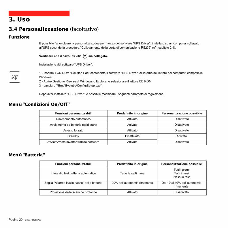
Pagina 20 - 34007117IT/AB
3. Uso
3.4 Personalizzazione (facoltativo)
Funzione
Funzioni personalizzabili
Riavviamento automatico
Avviamento da batteria (cold start)
Arresto forzato
Standby
Avvio/Arresto inverter tramite software
Predefinito in origine
Attivato
Attivato
Attivato
Disattivato
Attivato
È possibile far evolvere la personalizzazione per mezzo del software "UPS Driver", installato su un computer collegatoall’UPS secondo la procedura "Collegamento della porta di comunicazione RS232" (cfr. capitolo 2.4).
Verificare che il cavo RS 232 21 sia collegato.
Installazione del software "UPS Driver":
1 - Inserire il CD ROM "Solution Pac" contenente il software "UPS Driver" all’interno del lettore del computer, compatibileWindows.2 - Aprire Gestione Risorse di Windows o Explorer e selezionare il lettore CD ROM.3 - Lanciare "\Emb\Evolutio\Config\Setup.exe".
Dopo aver installato "UPS Driver", è possibile modificare i seguenti parametri di regolazione:
Menù "Batteria"
Funzioni personalizzabili
Intervallo test batteria automatico
Soglia "Allarme livello basso" della batteria
Protezione dalle scariche profonde
Predefinito in origine
Tutte le settimane
20% dell’autonomia rimanente
Attivato
Personalizzazione possibile
Tutti i giorniTutti i mesiNessun test
Dal 10 al 40% dell’autonomiarimanente
Disattivato
Personalizzazione possibile
Disattivato
Disattivato
Disattivato
Attivato
Disattivato
Menù "Condizioni On/Off"

34007117IT/AB - Pagina 21
3. Uso
Funzioni personalizzabili
Tensione di uscita in funzionamento a batteria
Soglia alta di passaggio sulla batteria
Soglia di attivazione della modalità "fader"
Soglia di attivazione della modalità "booster"
Soglia bassa di passaggio sulla batteria
Campo massimo di tensione di ingresso
Predefinito in origine
230 V
294 V
265 V
184 V
160 V
Disattivato
Personalizzazione possibile
200 V - 220 V - 240 V
da 271 a 294 V
da 244 a 265 V
da 184 a 207 V
da 160 a 180 V
Attivato (1)
Funzioni personalizzabili
Livello di sensibilità dell’UPS
Predefinito in origine
Normale
Personalizzazione possibile
Alta o bassa
Menù "Soglie di tensione"
Menù "Sensibilità"
Per maggiori informazioni riguardanti questi parametri consultare la rubrica Help del software "UPS Driver".
(1) Soglia bassa di passaggio sulla batteria = 150 V

Pagina 22 - 34007117IT/AB
Risoluzione avarie con intervento del Servizio Assistenza
4. Manutenzione
4.1 Risoluzione avarie
Sintomo
La spia 12 si accende edil segnalatore acusticoemette un bip continuo.
Diagnostica
L’UPS presenta un guasto rilevato dall’elettronicainterna.◗ Nessuna apparecchiatura è più alimentata.
Le apparecchiature collegate all’UPS non sono più protette.
Rimedio
Chiamare il Servizio Assistenza.
Sintomo
La spia 13 lampeggia edil segnalatore acusticoemette un bip.
La spia 12 lampeggia.
Diagnostica
L’UPS è in sovraccarico. Il consumo elettrico delleapparecchiature collegate all’UPS supera la capacità diquest’ultimo.
È stato individuato un difetto batteria durante il testautomatico della batteria.
Rimedio
Verificare la potenza assorbita dalleutenze e scollegare leapparecchiature non prioritarie.
Sostituire gli elementi batteria: vediil paragrafo 4.2.
Risoluzione avarie senza intervento del Servizio Assistenza (tutti i modelli)

34007117IT/AB - Pagina 23
P U L S A R
Evolution
1 5 0 0
B
A
C
4.2 Sostituzione del modulo batteria
4. Manutenzione
Smontaggio del modulo batteriaÈ possibile effettuare questa operazione senza arrestare l’UPS.
Richiamo sulle istruzioni di sicurezza:La batteria presenta un rischio di elettrocuzione ed una corrente di cortocircuito elevata. Per qualsiasi interventosugli elementi della batteria, occorre prendere le seguenti precauzioni:◗ Togliere orologi, anelli, fedi, braccialetti o qualsiasi altro oggetto metallico.◗ Utilizzare utensili con impugnatura isolata.
A - Sganciare la piastra recante il logoMGEUPS SYSTEMS sulla parte anterioredell'apparecchio. B - Svitare le due viti poste sul retro. C - Togliere la sezione di sinistra dellafaccia anteriore sollevandola leggermente,poi tirandola verso di sé.
Modelli "tower"
D - Scollegare il blocco batteria tirando suiconnettori (non tirare mai sul cavo).
D

Pagina 24 - 34007117IT/AB
4. Manutenzione
Rimontaggio del nuovo modulo batteriaRipetere le operazioni sopra descritte in senso inverso.
◗ Attenzione: rischio di arco elettrico durante il collegamento della batteria.◗ Per preservare la sicurezza e lo stesso livello di performance, utilizzare elementi batteria identici a quelli montatinell’UPS.◗ Badare ad inserire correttamente i componenti maschio e femmina del connettore durante il collegamento.
E - Estrarre il blocco batteria tirando sullalinguetta in plastica e procedere alla suasostituzione.
E

34007117IT/AB - Pagina 25
D
A
BC
P U L S A R
Evolution
1 5 0 0
4. Manutenzione
Smontaggio del modulo batteriaÈ possibile effettuare questa operazione senza arrestare l’UPS.
A - Sganciare la piastra recante il logoMGEUPS SYSTEMS sulla parte anterioredell'apparecchio. B - Svitare le due viti poste sul retro. C - Togliere la sezione di sinistra dellafaccia anteriore, tirandola verso di sé.
D - Scollegare il blocco batteria tirando suiconnettori (non tirare mai sul cavo).
Modelli "slot"

Pagina 26 - 34007117IT/AB
F
E
4. Manutenzione
Rimontaggio del nuovo modulo batteriaRipetere le operazioni sopra descritte in senso inverso.
◗ Attenzione: rischio di arco elettrico durante il collegamento della batteria.◗ Per preservare la sicurezza e lo stesso livello di performance, utilizzare elementi batteria identici a quelli montatinell’UPS.◗ Badare ad inserire correttamente i componenti maschio e femmina del connettore durante il collegamento.
E - Rimuovere tale copertura.
F - Estrarre il blocco batteria tirando sullalinguetta in plastica e procedere alla suasostituzione.
34007117IT/AB - Pagina 27
5. AmbienteQuesto prodotto è progettato nel rispetto dell’ambiente:
Non contiene né CFC né HCFC.
Riciclaggio dell’UPS al termine della durata del ciclo di vita:
MGE UPS SYSTEMS si impegna a far ritrattare, per mezzo di società autorizzate e conformi alle normative vigenti, latotalità dei prodotti recuperati al termine della durata del ciclo di vita (contattare la vostra agenzia).
Imballaggi:
Per il riciclaggio dell’imballaggio, conformarsi alle normative legali in vigore.
Avvertenza:
Questo prodotto contiene batterie al piombo. Il piombo è una sostanza pericolosa per l’ambiente qualora non sia riciclatada società specializzate.
Sito web: www.mgeups.com

Pagina 28 - 34007117IT/AB
6. Allegati
6.1 Caratteristiche tecnicheSchema sinottico
Ingresso
Uscita
Batterie
Carica batterieInverter
Trasformatore "booster/fader"Filtro

34007117IT/AB - Pagina 29
6. AllegatiCaratteristiche tecniche
Potenza di uscita
Rete elettrica dialimentazione◗ Tensione◗ Frequenza
Uscita in funzionamentoda batteria◗ Tensione◗ Frequenza
Batteria (Pb ermetico,senza manutenzione)◗ modello "tower"◗ modello "slot"
Ambiente◗ Soglia di rumore (infunzionamento da rete)◗ Temperatura difunzionamento◗ Umidità(senza condensa)
500
500 VA / 350 W
2 x 6 V - 9 Ah,
1100 / 1100 rack
1100 VA / 700 W
2 x 12 V - 9 Ah,4 x 6 V - 9 Ah
(1) Soglie alta e bassa regolabili mediante il software "UPS Driver".(2) Fino a 40 Hz in modalità di sensibilità bassa (programmabile mediante il software "UPS Driver").(3) Regolabile da 200 a 240 V mediante il software "UPS Driver".
800 / 800 rack
800 VA / 560 W
2 x 12 V - 7,2 Ah,4 x 6 V - 7,2 Ah
1500 / 1500 rack
1500 VA / 1000 W
3 x 12 V - 9 Ah,6 x 6 V - 9 Ah
Pulsar Evolution
Monofase da 160 V a 294 V (1), 230V nominale.
Monofase 230 V (3) (+6% / -10%)50/60 Hz +/- 0,1 Hz
<40 dBA
0 a 35° C
20 a 90%
<40 dBA
0 a 40° C
20 a 90%
da 47 Hz a 70 Hz (rete da 50 Hz) o da 56.5 Hz a 70 Hz (2) (rete da 60 Hz)

Pagina 30 - 34007117IT/AB
6. AllegatiEsempi di autonomie delle batterie
Pulsar Evolution 500
Pulsar Evolution 800
Pulsar Evolution 1100
1 router
Pulsar Evolution 1500
2 server ottimizzati slot
2 server di file/stampa
1 Hub
1 server + 1 router + 1 hub
0 10 20 50 100 t (min)30 40 60 70 80 90 110 120
0 10 20 50 100 t (min)30 40 60 70 80 90 110 120
3 server ottimizzati slot
1 router
1 Hub
2 server di file/stampa
1 server + 1 router + 1 hub
3 server ottimizzati slot
1 router
1 Hub
5 server ottimizzati slot
3 server di file/stampa
2 server + 1 router + 1 hub
1 router
0 10 20 50 100 t (min)30 40 60 70 80 90 110 120
0 10 20 50 100 t (min)30 40 60 70 80 90 110 120

34007117IT/AB - Pagina 31
6. Allegati
6.2 GlossarioAutonomia Durata di funzionamento dell’apparecchio da batteria in caso di impossibilità di utilizzo
della rete elettrica di alimentazione.
Barra dei LED Indicatore di potenza fornita o di autonomia della batteria sul pannello di controllo.
Fuori tensione UPS scollegato fisicamente dalla rete elettrica di alimentazione.
Interruttore di ingresso Apparecchio di protezione della rete elettrica contro i guasti dell’UPS.
Modalità "booster" Modalità di funzionamento automatico dell’UPS che consente di aumentare la tensionedella rete elettrica, in caso di debolezza di quest’ultima, al di sopra di un valore definitotramite la personalizzazione, il tutto senza scaricare la batteria.
Modalità "fader" Modalità di funzionamento automatico dell’UPS che consente di abbassare la tensionedella rete elettrica, in caso di valore troppo elevato di quest’ultima, al di sopra di unvalore definito tramite la personalizzazione, il tutto senza scaricare la batteria.
Personalizzazione Alcune funzioni dell’UPS possono essere modificate mediante il software "UPS Driver"al fine di soddisfare meglio le necessità dell’utente.
Porta di comunicazione RS232 Consente di collegare l’UPS ad un computer tramite la porta di comunicazione seriale.
Porta di comunicazione USB Consente di collegare l’UPS ad un computer tramite la porta di comunicazione USB.
Prese di uscita Pulsar Evolution comporta 2 prese di uscita non programmabili.
Prese programmabili Pulsar Evolution comporta 2 prese programmabili. Esse consentonol’avviamento sequenziale delle apparecchiature protette, l’alleggerimento di applicazioninon prioritarie in modalità batteria, o ancora la gestione delle priorità in fine autonomiadella batteria per conservare la più lunga autonomia delle apparecchiature più sensibili.La programmazione di queste prese si esegue per mezzo del software Solution Paccontenuto nel CD ROM in dotazione all’apparecchio.
Solution-Pac Suite di software di amministrazione, di personalizzazione e di sicurezza MGE UPSSYSTEMS contenuta nel CD ROM in dotazione all’apparecchio.
UPS Gruppo statico di continuità.
UPS Driver Software di comunicazione contenuto nel CD ROM in dotazione all’apparecchio checonsente di personalizzarlo in modo differente rispetto alla configurazione predefinita inorigine.
Utenze Apparecchi o dispositivi collegati in uscita dell’UPS.

Pagina 32 - 34007117IT/AB
6. Allegati
6.3 Indice analiticoAAmbiente ........................................................................ 27Arresto UPS tramite software ........................................ 20Autonomia batteria ......................................................... 30Avviamento .................................................................... 18Avviamento automatico .................................................. 20
BBarra dei LED .................................................................. 9Batteria
Fine autonomia batteria .......................................... 19Guasto ...................................................................... 9Passaggio a batteria ........................................... 9, 19Riciclaggio .............................................................. 27Soglia di allarme di fine autonomia ........................ 19Sostituzione .................................................. 22-23-24
CCaratteristiche tecniche ................................................. 29Collegamenti
Linea di dati ........................................................... 16Porta di comunicazione RS232 .............................. 16Porta di comunicazione USB ..................................16
DDimensioni ....................................................................... 7
GGuasto UPS ..................................................................... 9
IInterruttore
Batteria ..................................................................... 8Di ingresso ............................................................... 8
MModalità Standby ........................................................... 20
Avvio automatico .................................................... 20Modalità "booster" ...................................................... 9, 18Modalità "fader" .......................................................... 9, 18
PPersonalizzazione ......................................................... 20
Batteria .................................................................. 20Condizioni ON/OFF ................................................ 20Uscita .................................................................... 21
Peso ................................................................................. 7Porta di comunicazione RS232 ................................. 8, 16Porta di comunicazione USB .....................................8, 16Prese programmabili .................................................... 8, 9Pulsanti ............................................................................ 9
SScheda di comunicazione ......................................... 8, 17Segnalatore acustico ..................................................... 19Sicurezza ...................................................................... 23Sito web ........................................................................ 27Sostituzione delle batterie ................................. 22, 23, 24Sovraccarico ............................................................. 9, 22Spie ................................................................................. 9Standby .......................................................................... 20
TTemperatura ambiente eccessiva .................................. 29
UUPS Driver .................................................. 18, 19, 20, 29

34007117ES/AB - Página 1
Manual de instalacióny utilización
www.mgeups.com
NO
TH
IN
G
WI
LL
ST
OP
YO
UN O W
MGE UPS SYSTEMS
Pulsar Evolution1500 /1500 Rack1100 /1100 Rack800 /800 Rack
500 Rack

Página 2 - 34007117ES/AB

34007117ES/AB - Página 3
Introducción
Le agradecemos que haya seleccionado un producto MGE UPS SYSTEMS para la seguridad de sus equipos.
La gama Pulsar Evolution ha sido fabricada con el más amplio cuidado.Para aprovechar al máximo las prestaciones que le ofrece su SAI (Sistema de Alimentación Ininterrumpida), lerecomendamos que lea cuidadosamente este manual.
MGE UPS SYSTEMS está atento a los efectos que sus productos pudiesen causar en el medio ambiente.Por ello, los recursos que se han puesto en obra hacen que Pulsar Evolution sea una referencia en materia de proteccióndel medio ambiente y particularmente:
◗ una acción de fabricación ecológica durante su ciclo de desarrollo,◗ el reciclado de Pulsar Evolution al final de la vida útil del producto.
Le invitamos a que descubra la oferta de MGE UPS SYSTEMS, así como las opciones de la gama Pulsar Evolutionvisitando nuestro sitio web: www.mgeups.com o poniéndose en contacto con su representante MGE UPS SYSTEMS.
Importante: antes de la instalación y utilización del SAI, es imperativo leer atentamente las consignas de seguridad(documento n° 3400722200).

Página 4 - 34007117ES/AB
Prólogo
Estructura de la documentación
Respetar imperativamente estas consignas.
Información, consejos, ayuda.
Señalización visual.
Acción.
Señalización acústica.
Los convenios adoptados para representar los indicadores luminosos en los dibujos son los siguientes:
Indicador luminoso apagado.
Indicador luminoso encendido.
Indicador luminoso intermitente.
La búsqueda de información se efectúa principalmente de dos maneras, a partir del:◗ contenido,◗ índice.
Convenciones de los pictogramas

34007117ES/AB - Página 5
Contenido
1. Presentación1.1 Vistas generales .......................................................................................................................... 7
Modelos "torre" ............................................................................................................................... 7
Modelos "rack" ................................................................................................................................ 7
1.2 Caras traseras ............................................................................................................................. 8
1.3 Panel de control ............................................................................................................................ 9
2. Instalación2.1 Desembalaje y verificación ........................................................................................................ 10
Modelos "torre" ............................................................................................................................. 10
Modelos "rack" .............................................................................................................................. 11
2.2 Instalación ................................................................................................................................... 12
Modelos "torre" ............................................................................................................................. 12
Modelos "rack" 800/1100/1500 ..................................................................................................... 13
Modelo "rack" 500 ......................................................................................................................... 14
2.3 Conexión de los equipamientos ................................................................................................ 15
2.4 Conexión del puerto de comunicación RS232 o USB (opcional) ............................................ 16
2.5 Conexión de la protección línea de datos (opcional) ............................................................... 16
2.6 Instalación de la opción "tarjeta de comunicación" ................................................................ 17
3. Utilización3.1 Puesta en funcionamiento ......................................................................................................... 18
3.2 Cambio a modo "booster" o "fader" (en caso de variación de tensión de la red eléctrica) ...... 18
3.3 Alimentación con batería (en caso de ausencia de la red eléctrica) ......................................... 19
Cambio a batería .......................................................................................................................... 19
Umbral de alarma de fin de autonomía de la batería .................................................................... 19
3.4 Personalización (opcional) .......................................................................................................... 20
Función ......................................................................................................................................... 20
Ficha "condiciones On/Off" ........................................................................................................... 20
Ficha "Batería" .............................................................................................................................. 20
Ficha "Umbrales de tensión" ......................................................................................................... 21
Ficha "Sensibilidad" ...................................................................................................................... 21

Página 6 - 34007117ES/AB
Contenido
4. Mantenimiento4.1 Reparación .................................................................................................................................. 22
4.2 Cambio del módulo de batería ................................................................................................... 23
Modelos "torre" ............................................................................................................................. 23
Modelos "rack" .............................................................................................................................. 25
5. Medio ambiente ............................................................................................................................... 27
6. Anexos6.1 Características técnicas ............................................................................................................. 28
Esquema sinóptico ........................................................................................................................ 26
Características técnicas ................................................................................................................ 29
Ejemplos de autonomías de batería ............................................................................................. 30
6.2 Glosario ....................................................................................................................................... 31
6.3 Indice ............................................................................................................................................ 32

34007117ES/AB - Página 7
1. Presentación
1.1 Vistas generalesModelos "torre"
Modelos "rack"
Evolution 800
Evolution 1100
Evolution 1500
Peso en kg
10,5
11,5
15
Evolution 500 Rack
Evolution 800 Rack
Evolution 1100 Rack
Evolution 1500 Rack
Evolution 500 Rack
Evolution 800 Rack
Evolution 1100 Rack
Evolution 1500 Rack
Dimensiones en mm(L x A x P)
438 x 43,5 x 353
438 x 43,5 x 499
438 x 43,5 x 499
438 x 43,5 x 522(19") (1U)
Peso en kg
9
15,5
16
19
Evolution 800
Evolution 1100
Evolution 1500
Dimensiones en mm(L x A x P)
150 x 237 x 415
150 x 237 x 415
150 x 237 x 483
P U L S A R
Evolution
1 1 0 0
L
A
P
L
A
P
P U L S A R
Evolution
1500 Rack

Página 8 - 34007117ES/AB
1. Presentación
1.2 Caras traseras
Pulsar Evolution 500 / 800 / 1100 Rack
Puerto de comunicación USB.
Puerto de comunicación RS232.
Protección de las líneas de datos.
Emplazamiento para la opción "tarjetade comunicación".
Tomas para la conexión de losequipamientos.
Tomas programables (1 y 2).
Interruptor automático de protección dela red eléctrica de alimentación.
Toma para la conexión a la redeléctrica de alimentación.
1
2
3
4
5
6
7
8
1238 45
1 2
Pulsar Evolution 800 / 1100 / 1500
1
2
3
4
6
5
2
1
Pulsar Evolution 1500 Rack
8
6
12 384 5
1 2
6
7
7
7
Pulsar Evolution 1500 :

34007117ES/AB - Página 9
1 2
%%
1.3 Panel de control
Bargrafo del nivel de potencia utilizada en la salida.
Tomas programables 1 alimentadas.
Botón luminoso Encendido/Apagado (ON/OFF) de las tomas de salida.
Tomas programables 2 alimentadas.
Funcionamiento con batería.
10
11
12
15
14
18
17
13
16
1. Presentación
Defecto del aparato.
Defecto de la batería.
Sobrecarga del SAI.
Funcionamiento en modo "booster" o "fader".
Bargrafo del nivel de carga de la batería.
De 0 a 25%.
De 26 a 50%.
De 51 a 75%.
De 76 a 100%.

Página 10 - 34007117ES/AB
2. Instalación
2.1 Desembalaje y verificación
2 cables para conectar los equipamientos.
Cable de comunicación RS232.
Cable de comunicación USB.
CD-ROM que contiene los software "Solución Pac" y "UPS Driver".
Documentación.
23
21
20
21
22
23
24
2220
24
30
Modelos "torre"
P U L S A R
Evolution
1 1 0 0

34007117ES/AB - Página 11
2. Instalación
2 cables para conectar los equipamientos.
Cable de comunicación RS232.
Cable de comunicación USB.
CD-ROM que contiene los software "Solución Pac" y "UPS Driver".
Documentación.
Kit de montaje en armario 19".
Sistema de bloqueo de los cables de alimentación de los equipamientos.
20
21
22
23
24
25
26
26
21 2220
2423 25
Modelos "rack"
P U L S A R
Evolut ion
1500 Rack
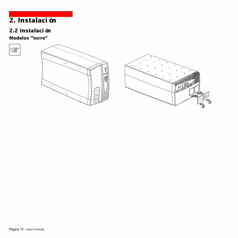
Página 12 - 34007117ES/AB
2. Instalación
2.2 InstalaciónModelos "torre"
P U L S A
R
Evolutio
n
1 1 0 0
P U L S A R
Evolution
1 1 0 0

34007117ES/AB - Página 13
2. Instalación
Montaje y fijación de las guías y del rack: seguir las etapas de 1 a 6.
MGE UPS SYSTEMS entrega los tornillos de fijación y las guías.
12
22
2
53
6
6
5
4
3
Modelos "rack" 800/1100/1500
P U L S A R
Evolution
1500 Rack

Página 14 - 34007117ES/AB
2. InstalaciónModelos "rack" 500
1
2
3
3
1
P U L S A R
Evolution
1500 Rack
P U L S A R
Evolution
1500 Rack
P U L S A R
Evolution
1500 Rack

34007117ES/AB - Página 15
2.3 Conexión de los equipamientos
Verificar que las indicaciones señaladas en la placa de identificación situada en la parte trasera del aparatocorrespondan a la red eléctrica de alimentación y al consumo eléctrico real de los equipamientos.
1 - Desconectar el cable de alimentación delequipamiento.
2 - Conectar este cable␣ (1) en la toma 8 yluego en la toma de la red eléctrica dealimentación.
3 - Conectar los equipamientos al SAI conlos cables 20 .Conectar de preferencia los equipamientosprioritarios en las 2 tomas 5 y losequipamientos no prioritarios en las 2 tomas␣ ␣ 6 programables (1 y 2).
Para poder programar la paradade las tomas 6 durante laautonomía de la batería yoptimizar así la duración de estaautonomía, se necesita acceder alsoftware de comunicación MGEUPS SYSTEMS.
4 - Bloquear la conexión fijando el sistema␣ 26 (en los modelos "rack" únicamente).
5
6
2. Instalación
8
Después de la primera puesta bajo tensión, se necesitan al menos 8 horas para que la batería pueda suministrar laautonomía nominal.
(1) Cerciorarse de que las características de estecable son: 250V-10A (sección 1 mm2, tipo HO5).
20
2
1
Las consignas de abajo se ilustran con vistas de un modelo Pulsar Evolution 1500 "torre". El principio es idéntico en losotros modelos "torre" y "rack".

Página 16 - 34007117ES/AB
RS232
2. Instalación
2.4 Conexión del puerto de comunicación RS232 o USB (opcional)
1 - Conectar el cable de comunicación RS232 21 o USB 22 en el puerto serie oUSB del equipo informático.
2 - Conectar el otro extremo del cable decomunicación 21 o 22 en el puerto decomunicación RS232 2 o USB 1 delSAI.
A partir de este momento, el SAI puededialogar con un software de administración,de personalización o de seguridad MGEUPS SYSTEMS.
21
22
El puerto de comunicación RS 232y el puerto de comunicación USBno pueden funcionarsimultáneamente.
2.5 Conexión de la protección de la línea de datos (opcional)La función "protección de las líneas dedatos" del SAI permite eliminar lassobretensiones transmitidas en las líneas delas redes informáticas.Para ello, hacer transitar la línea que sedesea proteger por el SAI, utilizando lastomas "Data línea protección" IN (entrada) yOUT (salida) como se indica en la figura deal lado (cables RJ45 no suministrados).
1
2
IN OUT
RS232
DATA LINEPROTECTION
Las consignas de abajo se ilustran con vistas de un modelo Pulsar Evolution 1500 "torre". El principio es idéntico en losotros modelos "torre" y "rack".

34007117ES/AB - Página 17
2. Instalación
2.6 Instalación de la opción "tarjeta de comunicación"
1 - Retirar el protector 4 del SAI fijado con2 tornillos.
2 - Colocar la tarjeta en el lugar previsto.
3 - Fijar el protector de la tarjeta con 2tornillos.
Emplazamiento de latarjeta de comunicación,con acceso restringido.
4
No se necesita apagar el SAI para instalar una tarjeta de comunicación.Esta operación deberá ser efectuada por personal cualificado.
IN OUTDATA LINE PROTECTION
RS232
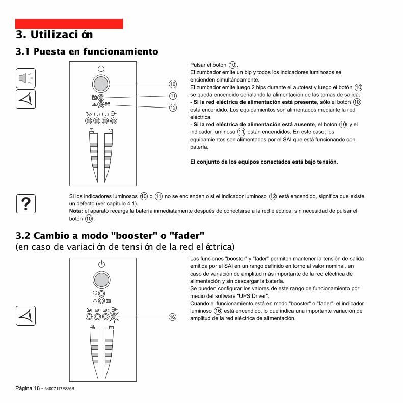
Página 18 - 34007117ES/AB
1 2
%%
3. Utilización
3.1 Puesta en funcionamiento
10
11
12
Pulsar el botón 10 .El zumbador emite un bip y todos los indicadores luminosos seencienden simultáneamente.El zumbador emite luego 2 bips durante el autotest y luego el botón 10se queda encendido señalando la alimentación de las tomas de salida.- Si la red eléctrica de alimentación está presente, sólo el botón 10está encendido. Los equipamientos son alimentados mediante la redeléctrica.- Si la red eléctrica de alimentación está ausente, el botón 10 y elindicador luminoso 11 están encendidos. En este caso, losequipamientos son alimentados por el SAI que está funcionando conbatería.
El conjunto de los equipos conectados está bajo tensión.
1 2
%%
3.2 Cambio a modo "booster" o "fader"(en caso de variación de tensión de la red eléctrica)
16
Las funciones "booster" y "fader" permiten mantener la tensión de salidaemitida por el SAI en un rango definido en torno al valor nominal, encaso de variación de amplitud más importante de la red eléctrica dealimentación y sin descargar la batería.Se pueden configurar los valores de este rango de funcionamiento pormedio del software "UPS Driver".Cuando el funcionamiento está en modo "booster" o "fader", el indicadorluminoso 16 está encendido, lo que indica una importante variación deamplitud de la red eléctrica de alimentación.
Si los indicadores luminosos 10 o 11 no se encienden o si el indicador luminoso 12 está encendido, significa que existeun defecto (ver capítulo 4.1).Nota: el aparato recarga la batería inmediatamente después de conectarse a la red eléctrica, sin necesidad de pulsar elbotón 10 .

34007117ES/AB - Página 19
1 2
%%
1 2
%%
3. Utilización
3.3 Alimentación con batería (en caso de ausencia de la red eléctrica)Cambio a batería
Cuando la red eléctrica se encuentra fuera de tolerancias, el indicador␣ ␣ 11 está encendido.En toda la duración de autonomía de la batería, el zumbador emite unbip cada 10 segundos.
Los equipos conectados al SAI siguen siendo alimentados por labatería.
Umbral de alarma de fin de autonomía de la bateríaCuando se alcanza ese umbral, el zumbador emite un bip cada 3segundos.El umbral de alarma puede personalizarse con el software "UPS Driver".
Sólo queda muy poca autonomía en la batería, por lo que sedeberán cerrar las aplicaciones, ya que queda muy poco tiempoantes de que el SAI se apague automáticamente.
Cuando se termina la autonomía de batería, el SAI se apaga y todos losindicadores luminosos se apagan.
Los equipos conectados al SAI dejan de estar alimentados.
11
El SAI arranca automáticamente cuando vuelve la red eléctricaSi el SAI no se enciende, compruebe que el arranque automático por reanudación de la red eléctrica no esté desactivado(ver capítulo 3.4 "Personalización").
11

Página 20 - 34007117ES/AB
3. Utilización
3.4 Personalización (opcional)
Función
Funciones personalizables
Inicio automático
Inicio con batería (cold star)
Paro forzado
Puesta en reposo
Encendido/Paro ondulador con software
Configuración de fábrica
Activado
Activado
Activado
Desactivado
Activado
Se pueden modificar los parámetros de personalización del SAI con el software "UPS Driver" instalado en el ordenadorconectado al SAI según el procedimiento "Conexión del puerto de comunicación RS232" (ver capítulo 2.4).
Verificar que el cable RS 232 21 esté conectado.
Instalación del software "UPS Driver":
1 - Insertar el CD ROM "Solución Pac" que contiene el software "UPS Driver" en el lector de su ordenador compatibleWindows.2 - Abrir el gestor de archivos Windows o el explorador y seleccionar el lector de CD ROM.3 - Lanzar "\Emb\Evolutio\Config\Setup.exe".
Después de haber instalado "UPS Driver", usted podrá modificar los siguientes parámetros de reglaje:
Ficha "Batería"
Funciones personalizables
Intervalo de la prueba automática de la batería
Umbral "Alarma nivel bajo" de la batería
Protección contra descargas profundas
Configuración de fábrica
Cada semana
20% de autonomía restante
Activado
Personalización posible
DiarioCada mesSin prueba
de 10 a 40%de autonomía restante
Desactivado
Personalización posible
Desactivado
Desactivado
Desactivado
Activado
Desactivado
Ficha "Condiciones On/Off"

34007117ES/AB - Página 21
3. Utilización
Funciones personalizables
Tensión de salida en funcionamiento con batería
Umbral superior de cambio a batería
Umbral de activación del modo "fader"
Umbral de activación del modo "booster"
Umbral inferior de cambio a batería
Rango máximo de tensión de entrada
Configuración de fábrica
230 V
294 V
265 V
184 V
160 V
Desactivado
Personalización posible
200 V - 220 V - 240 V
271 a 294 V
244 a 265 V
184 a 207 V
160 a 180 V
Activado (1)
Funciones personalizables
Nivel de sensibilidad del SAI
Configuración de fábrica
Normal
Personalización posible
Alto o bajo
Ficha "Umbrales de tensión"
Ficha "Sensibilidad"
Para más informaciones sobre estos parámetros, ver el apartado "Ayuda" del "UPS Driver".
(1) Umbral inferior de cambio a batería = 150 V

Página 22 - 34007117ES/AB
Reparación con intervención del servicio posventa
4. Mantenimiento
4.1 Reparación
Síntoma
El indicador 12 seenciende y el zumbadoremite sonidos acústicoscontinuos.
Diagnóstico
El SAI presenta un defecto detectado por laelectrónica interna.◗ El conjunto de equipos ha dejado de ser alimentado.
Los equipos conectados al SAI ya no están protegidos.
Solución
Llamar al servicio posventa.
Síntoma
El indicador 13 seenciende y el zumbadoremite un bip.
El indicador 12 parpadea
Diagnóstico
El SAI se está sobrecargando. El consumo eléctrico delos equipamientos conectados al SAI excede lacapacidad de este último.
Se detectó un defecto de la batería durante la pruebaautomática de la misma.
Solución
Comprobar la potencia absorbidapor los equipos y desconectaraquellos que no sean prioritarios.
Reemplazar los elementos debatería: ver el párrafo 4.2.
Reparación sin intervención del servicio posventa (todos los modelos)

34007117ES/AB - Página 23
P U L S A R
Evolution
1 5 0 0
B
A
C
4.2 Cambio del módulo batería
4. Mantenimiento
Desmontaje del módulo bateríaEsta operación puede efectuarse sin tener que parar el SAI.
Recapitulación de las consignas de seguridad:La batería presenta un riesgo de electrocución y una elevada corriente de cortocircuito. Se deberán tomar lasprecauciones siguientes para cualquier intervención que se realice en los elementos de la batería:◗ Quitarse reloj, anillos, alianzas, brazaletes o cualquier otro objeto metálico,◗ Utilizar herramientas con mango aislado.
A - Retirar la placa con el logotipo MGEsituada en la cara delantera del aparato. B - Destornillar los dos tornillos situadosdetrás de la placa. C - Retirar la sección izquierda de la caradelantera levantándola ligeramente y luegotirándola hacia usted.
Modelos "torre"
D
D - Desconectar el bloque de bateríatirando de los conectadores (no tire nuncade los cables).

Página 24 - 34007117ES/AB
4. Mantenimiento
Montaje del nuevo módulo de la bateríaRealizar en sentido inverso las operaciones que se describen arriba.
◗ Atención: riesgo de arco eléctrico durante la conexión de la batería.◗ Para preservar la seguridad y el mismo nivel de eficacia, utilizar elementos de batería idénticos a los que estánmontados en el SAI.◗ Cuidar en meter a fondo las partes macho y hembra del conector al realizar la conexión.
E - Extraer el bloque de batería tirando dela lengüeta de plástico y proceder a sucambio.
E

34007117ES/AB - Página 25
D
A
BC
P U L S A R
Evolution
1 5 0 0
4. Mantenimiento
Desmontaje del módulo bateríaEsta operación puede efectuarse sin tener que parar el SAI.
A - Retirar la placa con el logotipo MGEsituada en la cara delantera del aparato. B - Destornillar los dos tornillos situadosdetrás de la placa. C - Retirar la sección izquierda de la caradelantera tirándola hacia usted.
D - Desconectar el bloque de bateríatirando de los conectadores (no tire nuncade los cables).
Modelos "rack"
␣

Página 26 - 34007117ES/AB
F
E
4. Mantenimiento
Montaje del nuevo módulo de la bateríaRealizar en sentido inverso las operaciones que se describen arriba.
◗ Atención: riesgo de arco eléctrico durante la conexión de la batería.◗ Para preservar la seguridad y el mismo nivel de eficacia, utilizar elementos de batería idénticos a los que estánmontados en el SAI.◗ Cuidar en meter a fondo las partes macho y hembra del conector al realizar la conexión.
E - Levantar ese capó.
F - Extraer el bloque de batería tirando dela lengüeta de plástico y proceder a sucambio.

34007117ES/AB - Página 27
5. Medio AmbienteEste producto ha sido diseñado para respetar el medio ambiente:
No contiene CFC ni HCFC.
Reciclado del SAI al final de su funcionamiento útil:
MGE UPS SYSTEMS se compromete a utilizar los servicios de sociedades autorizadas y conformes con la reglamentaciónpara que retiren el conjunto de productos recuperados al final de su vida útil (póngase en contacto con su agencia).
Embalaje:
Para el reciclado del embalaje, confórmese con las exigencias legales en vigor.
Aviso:
Este producto contiene baterías de plomo. El plomo es una substancia peligrosa para el medio ambiente si no es recicladopor organismos especializados.
Sitio Web : www.mgeups.com

Página 28 - 34007117ES/AB
6. Anexos
6.1 Características técnicasEsquema sinóptico
Entrada
Salida
Batería
CargadorOndulador
Transformador "booster/fader"Filtro

34007117ES/AB - Página 29
6. AnexosCaracterísticas técnicas
Potencia de salida
Red eléctrica dealimentación◗ Tensión◗ Frecuencia
Salida utilización enfuncionamiento conbatería◗ Tensión◗ Frecuencia
Batería (Plomo estanco,sin mantenimiento)◗ modelos "torre"◗ modelos "rack"
Medio ambiente◗ Nivel de ruido(funcionamiento con red)◗ Temperatura defuncionamiento◗ Humedad(sin condensación)
500
500 VA / 350 W
2 x 6 V - 9 Ah,
1100 / 1100 rack
1100 VA / 700 W
2 x 12 V - 9 Ah,4 x 6 V - 9 Ah
(1) Umbrales superior e inferior ajustables por el software "UPS Driver".(2) Hasta 40 Hz en modo de sensibilidad baja (programable por el software "UPS Driver").(3) Ajustable de 200 a 240 V por el software "UPS Driver".
800 / 800 rack
800 VA / 560 W
2 x 12 V - 7,2 Ah,4 x 6 V - 7,2 Ah
1500 / 1500 rack
1500 VA / 1000 W
3 x 12 V - 9 Ah,6 x 6 V - 9 Ah
Pulsar Evolution
Monofásica 160 V a 294 V (1), 230V nominal
Monofásica 230 V (3) (+6% / -10%)50/60 Hz +/- 0,1 Hz
<40 dBA
0 a 35° C
20 a 90%
<40 dBA
0 a 40° C
20 a 90%
47 Hz a 70 Hz (red 50 Hz) o 56,5 Hz a 70 Hz (2) (red 60 Hz)

Página 30 - 34007117ES/AB
6. AnexosEjemplos de autonomías de batería
Pulsar Evolution 500
Pulsar Evolution 800
Pulsar Evolution 1100
1 Hub
1 clasificador
Pulsar Evolution 1500
2 servidores optimizados rack
2 servidores de ficheros/deimpresión
1 servidor + 1 clasificador + 1 Hub
0 10 20 50 100 t (min)30 40 60 70 80 90 110 120
0 10 20 50 100 t (min)30 40 60 70 80 90 110 120
0 10 20 50 100 t (min)30 40 60 70 80 90 110 120
0 10 20 50 100 t (min)30 40 60 70 80 90 110 120
3 servidores optimizados rack
1 Hub
1 clasificador
2 servidores de ficheros/deimpresión
1 servidor + 1 clasificador + 1 Hub
3 servidores optimizados rack
1 Hub
1 clasificador
5 servidores optimizados rack
3 servidores de ficheros/deimpresión
2 servidores + 1 clasificador+ 1 Hub
1 clasificador

34007117ES/AB - Página 31
6. Anexos
6.2 GlosarioAutonomía Duración de funcionamiento del aparato con la batería en caso de imposibilidad de
utilización de la red eléctrica de alimentación.
Bargrafo Indicador de potencia suministrada o de autonomía de la batería en el panel de control.
Equipamientos Aparatos o dispositivos conectados en las salida del SAI.
Fuera de tensión SAI desconectado físicamente de la red eléctrica de alimentación.
Interruptor automático Aparato de protección de la red eléctrica contra los defectos del SAI.de entrada
Modo "booster" Modo de funcionamiento automático del SAI que permite subir la tensión de la redeléctrica, en caso de que esté baja, por encima de un valor definido en los parámetrosde personalización, sin tener que descargar la batería.
Modo "fader" Modo de funcionamiento automático del SAI que permite bajar la tensión de la redeléctrica, en caso de que tenga un valor muy elevado, por abajo de un valor definido enlos parámetros de personalización, sin tener que descargar la batería.
Personalización Algunas funciones del SAI pueden modificarse MEDIANTE el software "UPS Driver"para satisfacer mejor las necesidades del usuario.
Puerto de comunicación RS232 Permite conectar el SAI a un ordenador a través del puerto de comunicación serie.
Puerto de comunicación USB Permite conectar el SAI a un ordenador a través del puerto de comunicación USB.
SAI Sistema de Alimentación Ininterrumpida.
Solución Pac Serie de programas de administración, personalización y de seguridad MGE UPSSYSTEMS contenida en el CD ROM que se entrega con el aparato.
Tomas de salida Pulsar Evolution cuenta 2 tomas de salida no programables.
Tomas programables Pulsar Evolution cuenta 2 tomas programables. Permiten el iniciosecuencial de los equipamientos protegidos, la desconexión de aplicaciones noprioritarias en modo batería o incluso la gestión de prioridades al final de autonomía dela batería para conservar la mayor autonomía en los equipamientos más sensibles. Laprogramación de estas tomas se hace mediante el software "Solution Pac" que seencuentra en el CD ROM que se entrega con el aparato.
UPS Driver Software de comunicación contenido en el CD ROM que se entrega con el aparato ypermite personalizar los parámetros de manera diferente a la configuración de fábrica.

Página 32 - 34007117ES/AB
6. Anexos
6.3 IndiceAArranque automático ...................................................... 20Autonomía de la batería ................................................. 30
BBargrafo ........................................................................... 9Batería
Cambio a batería ................................................ 9, 19Cambio del módulo batería .......................... 22-23-24Defecto ..................................................................... 9Fin de autonomía de la batería .............................. 19Reciclado ................................................................ 27Umbral de alarma de fin de autonomía .................. 19
CCambio de las baterías ..................................... 22, 23, 24Características técnicas ................................................. 29Conexiones
Línea de datos ....................................................... 16Puerto de comunicación RS232 ............................ 16Puerto de comunicación USB ................................ 16
DDefecto SAI ...................................................................... 9Dimensiones .................................................................... 7
IIndicadores luminosos .................................................... 9Interruptor automático
batería ...................................................................... 8de entrada ................................................................ 8
MMedio ambiente ............................................................. 27Modo "booster" .......................................................... 9, 18Modo "fader" .............................................................. 9, 18
PParo del SAI por software .............................................. 20Personalización ............................................................. 20
Batería .................................................................... 20Condiciones On/Off ................................................ 20Salida .................................................................... 21
Peso ................................................................................. 7Puerto de comunicación RS232 ............................... 8, 16Puerto de comunicación USB ................................... 8, 16Puesta en funcionamiento ............................................. 18Puesta en reposo ........................................................... 20
Inicio automático .................................................... 20Pulsadores ....................................................................... 9
RReposo ........................................................................... 20
SSeguridad ...................................................................... 23Sitio web ........................................................................ 27Sobrecarga ................................................................9, 22
TTarjeta de comunicación ............................................8, 17Temperatura ambiente excesiva ................................... 29Tomas programables .................................................. 8, 9
UUPS Driver .................................................. 18, 19, 20, 29
ZZumbador ....................................................................... 19

34007117NL/AB - Pagina 1
www.mgeups.com
NO
TH
IN
G
WI
LL
ST
OP
YO
UN O W
Installatie- engebruikershandleiding
MGE UPS SYSTEMS
Pulsar Evolution1500 /1500 Rack1100 /1100 Rack800 /800 Rack
500 Rack

Pagina 2 - 34007117NL/AB

34007117NL/AB - Pagina 3
Inleiding
Wij danken u voor uw keuze van een MGE UPS SYSTEMS product om uw apparatuur te beveiligen.
De Pulsar Evolution-reeks is met de grootste zorg ontwikkeld.Voor een optimaal gebruik van uw UPS (Uninterruptible Power Supply – Ononderbroken Stroomvoorziening) adviseren wiju deze gebruikershandleiding aandachtig te lezen.
MGE UPS SYSTEMS besteedt veel aandacht aan de invloed van zijn producten op het milieu.De aandacht die is besteed aan de milieu aspecten maken van de Pulsar Evolution dé referentie op dit gebied:◗ milieubewuste benadering tijdens het hele productontwikkelingsproces,◗ recycleren van de Pulsar Evolution aan het einde van zijn levensduur.
Ontdek de Pulsar Evolution-reeks en alle andere MGE UPS SYSTEMS producten door onze web site te bezoeken:www.mgeups.com of contact op te nemen met uw MGE UPS SYSTEMS dealer.
Belangrijk: Vooraleer UPS te installeren en te gebruiken, is het noodzakelijk om aandachtig de veiligheidsinstructies telezen (document n° 340072200).

Pagina 4 - 34007117NL/AB
Voorwoord
Indeling van de documentatie
Deze instructies moeten strikt inachtgenomen worden.
Informatie, tips, hulp.
Visueel signaal.
Handeling.
Geluidssignaal.
De status van de LED’s wordt als volgt weergegeven:
LED uit.
LED aan.
LED knippert.
Er zijn twee manieren om informatie op te zoeken:◗ via de inhoudsopgave,◗ via de index.
Verklaring der tekens

34007117NL/AB - Pagina 5
Inhoudsopgave
1. Beschrijving1.1 Algemeen overzicht .................................................................................................................... 7
"Tower" modellen ............................................................................................................................ 7
"Rack" modellen .............................................................................................................................. 7
1.2 Achterzijde ................................................................................................................................... 8
1.3 Bedieningspaneel ......................................................................................................................... 9
2. Installeren2.1 Uitpakken en controleren ........................................................................................................... 10
"Tower" modellen .......................................................................................................................... 10
"Rack" modellen ............................................................................................................................ 11
2.2 Installatie ..................................................................................................................................... 12
"Tower" modellen .......................................................................................................................... 12
800/1100/1500 "rack" modellen .................................................................................................... 13
500 "rack" model ........................................................................................................................... 14
2.3 Aansluiten van de te beveiligen apparatuur ............................................................................. 15
2.4 Aansluiten van de RS232- of USB-communicatiepoort (optioneel) ........................................ 16
2.5 Aansluiten van de beveiliging van datalijnen (optioneel) ....................................................... 16
2.6 Aanbrengen van de optionele "communicatiekaart" .............................................................. 17
3. Gebruik3.1 Inschakelen ................................................................................................................................. 18
3.2 Overschakelen op "booster" of "fader" functie
(bij spanningsvariaties op het netstroomcircuit) ............................................................................ 18
3.3 Energievoorziening door batterij (bij afwezigheid van netstroomcircuit) .................................. 19
Overschakelen op batterij ............................................................................................................. 19
Alarmgrens einde autonomie batterij bereikt ................................................................................ 19
3.4 Specifieke programmering (optioneel) ....................................................................................... 20
Functie .......................................................................................................................................... 20
Indexkaart "Aan/Uit"-functies ........................................................................................................ 20
Indexkaart "Batterij" ...................................................................................................................... 20
Indexkaart "Spanningsdrempels" .................................................................................................. 21
Indexkaart "Gevoeligheid" ............................................................................................................. 21

Pagina 6 - 34007117NL/AB
Inhoudsopgave
4. Onderhoud4.1 Storingen verhelpen ................................................................................................................... 22
4.2 Batterijmodule vervangen .......................................................................................................... 23
"Tower" modellen .......................................................................................................................... 23
"Rack" modellen ............................................................................................................................ 25
5. Milieu.................................................................................................................................................... 27
6. Bijlagen6.1 Technische specificaties ............................................................................................................ 28
Overzichtsschema ........................................................................................................................ 26
Technische specificaties ............................................................................................................... 29
Voorbeelden van batterij-autonomie ............................................................................................. 30
6.2 Woordenlijst ................................................................................................................................ 31
6.3 Index............................................................................................................................................. 32

34007117NL/AB - Pagina 7
1. Beschrijving
1.1 Algemeen overzicht"Tower" modellen
"Rack" modellen
Evolution 800
Evolution 1100
Evolution 1500
Gewicht in kg
10,5
11,5
15
Evolution 500 Rack
Evolution 800 Rack
Evolution 1100 Rack
Evolution 1500 Rack
Evolution 500 Rack
Evolution 800 Rack
Evolution 1100 Rack
Evolution 1500 Rack
Afmetingen in mm(breedte x hoogte x diepte)
438 x 43,5 x 353
438 x 43,5 x 499
438 x 43,5 x 499
438 x 43,5 x 522(19") (1U)
Gewicht in kg
9
15,5
16
19
Evolution 800
Evolution 1100
Evolution 1500
Afmetingen in mm(breedte x hoogte x diepte)
150 x 237 x 415
150 x 237 x 415
150 x 237 x 483
P U L S A R
Evolution
1 1 0 0
B
H
D
B
H
D
P U L S A R
Evolution
1500 Rack
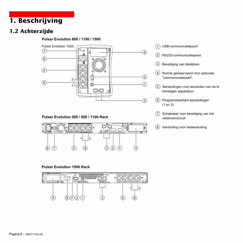
Pagina 8 - 34007117NL/AB
1. Beschrijving
1.2 Achterzijde
Pulsar Evolution 500 / 800 / 1100 Rack
USB-communicatiepoort.
RS232-communicatiepoort.
Beveiliging van datalijnen.
Ruimte gereserveerd voor optionele"communicatiekaart".
Aansluitingen voor aansluiten van de tebeveiligen apparatuur.
Programmeerbare aansluitingen(1 en 2).
Schakelaar voor beveiliging van hetnetstroomcircuit.
Aansluiting voor netaansluiting.
1
2
3
4
5
6
7
8
1238 45
1 2
Pulsar Evolution 800 / 1100 / 1500
1
2
3
4
6
5
2
1
Pulsar Evolution 1500 Rack
8
6
12 384 5
1 2
6
7
7
7
Pulsar Evolution 1500:

34007117NL/AB - Pagina 9
1 2
%%
1.3 Bedieningspaneel
10
11
12
15
14
18
17
13
16
1. Beschrijving
Display van het niveau van het aan de uitgang afgenomen vermogen.
Programmeerbare aansluitingen 1 onder spanning.
Verlichte aan/uit-knop (ON/OFF) van de uitgangsaansluitingen.
Programmeerbare aansluitingen 2 onder spanning.
Werking op batterij.
Fout elektronica.
Fout batterij.
UPS overbelast.
Werking in "booster" of "fader" functie.
Display van het laadniveau van de batterij.
0 tot 25%.
26 tot 50%.
51 tot 75%.
76 tot 100%.
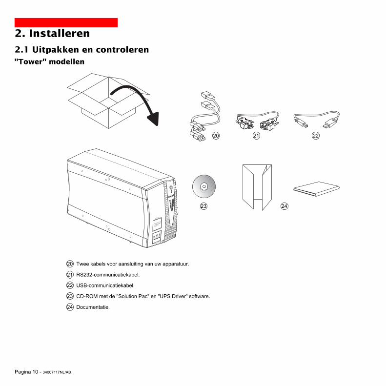
Pagina 10 - 34007117NL/AB
2. Installeren
2.1 Uitpakken en controleren
Twee kabels voor aansluiting van uw apparatuur.
RS232-communicatiekabel.
USB-communicatiekabel.
CD-ROM met de "Solution Pac" en "UPS Driver" software.
Documentatie.
23
21
20
21
22
23
24
2220
24
30
"Tower" modellen
P U L S A R
Evolution
1 1 0 0

34007117NL/AB - Pagina 11
2. Installeren
Twee kabels voor aansluiting van uw apparatuur.
RS232-communicatiekabel.
USB-communicatiekabel.
CD-ROM met de "Solution Pac" en "UPS Driver" software.
Documentatie.
Set voor montage in 19"-rack.
Steun voor plaatsing in verticale stand.
20
21
22
23
24
25
26
26
21 2220
2423 25
"Rack" modellen
P U L S A R
Evolut ion
1500 Rack

Pagina 12 - 34007117NL/AB
2. Installeren
2.2 Installatie"Tower" modellen
P U L S A
R
Evolutio
n
1 1 0 0
P U L S A R
Evolution
1 1 0 0
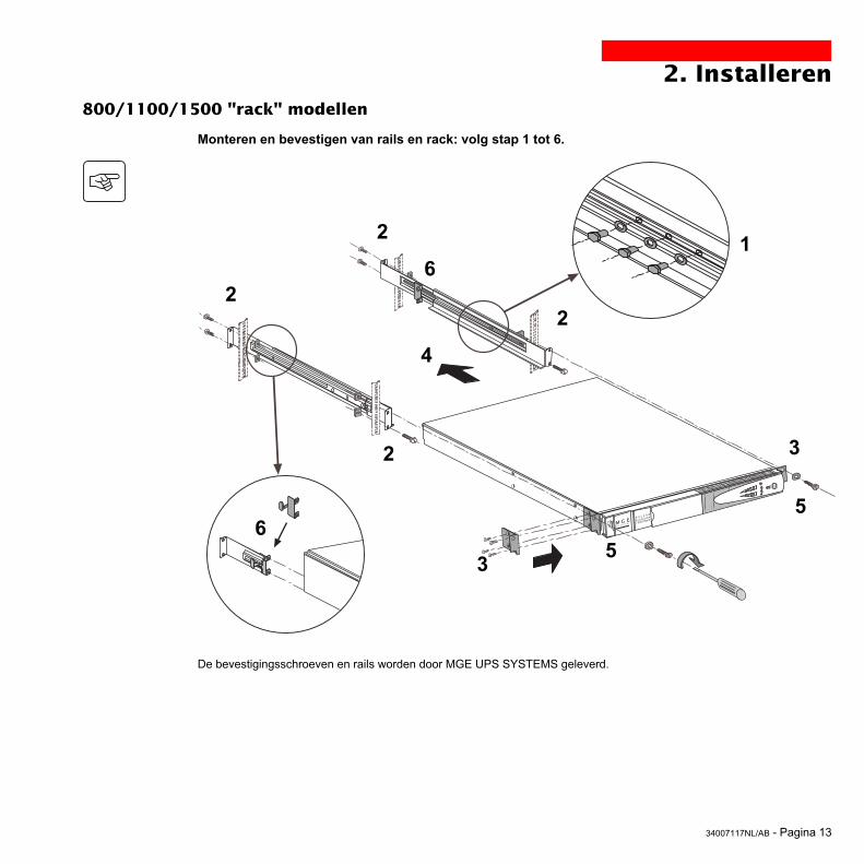
34007117NL/AB - Pagina 13
2. Installeren
Monteren en bevestigen van rails en rack: volg stap 1 tot 6.
De bevestigingsschroeven en rails worden door MGE UPS SYSTEMS geleverd.
12
22
2
53
6
6
5
4
3
800/1100/1500 "rack" modellen
P U L S A R
Evolution
1500 Rack
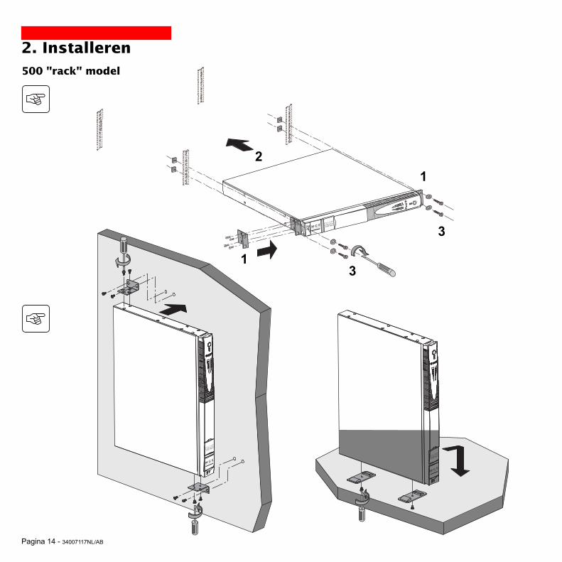
Pagina 14 - 34007117NL/AB
2. Installeren500 "rack" model
1
2
3
3
1
P U L S A R
Evolution
1500 Rack
P U L S A R
Evolution
1500 Rack
P U L S A R
Evolution
1500 Rack

34007117NL/AB - Pagina 15
2.4 Aansluiten van de te beveiligen apparatuur
Controleer of de specificaties op het typeplaatje aan de achterzijde van het apparaat overeenkomen met uwnetspanning en het werkelijke stroomverbruik van de aangesloten apparatuur.
1 - Koppel de voedingskabel van deapparatuur los.
2 - Sluit deze kabel (1) aan op de aansluiting␣ ␣ 8 en vervolgens op de wandcontactdoos.
3 - Sluit de te beveiligen apparatuur op deUPS aan met behulp van de kabels 20 .Sluit bij voorkeur de primaire apparatuur aanop de 2 aansluitingen 5 en de secundaireapparatuur op de 2 programmeerbareaansluitingen 6 (1 en 2).
De aansluitingen 6 kunnentijdens batterij-autonomie in de off-positie worden gezet om de duurvan de autonomie te optimaliseren.Dit kan echter alleen via de MGEUPS SYSTEMScommunicatiesoftware wordengeprogrammeerd.
4 - Vergrendel de aansluitingen met behulpvan onderdeel 26 (alleen bij “rack”modellen).
5
6
2. Installeren
8
Na de eerste keer inschakelen duurt het minstens 8 uur voordat de batterij de nominale autonomie kan leveren.
(1) Controleer of deze kabel de volgendespecificaties heeft: 250V-10A (diameter 1␣ mm2,type HO5).
20
2
1
Op de illustratie bij de onderstaande instructies is de Pulsar Evolution 1500 "tower" te zien. Maar het principe is hetzelfdevoor alle “tower” en “rack” modellen.

Pagina 16 - 34007117NL/AB
RS232
2. Installeren
2.4 Aansluiten van de RS232- of USB-communicatiepoort (optioneel)
1 - Sluit de RS232-communicatiekabel 21of de USB-communicatiekabel 22 aan opde seriële of de USB-poort van decomputerapparatuur.
2 - Sluit het andere uiteinde van decommunicatiekabel 21 of 22 aan op deRS232-communicatiepoort 2 of de USB-communicatiepoort 1 van de UPS.
De UPS kan nu communiceren met eenbeheer-, programmeer- ofbeveiligingssoftware van MGE UPSSYSTEMS.
21
22
De RS232- en de USB-communicatiepoort kunnen niettegelijkertijd functioneren.
2.5 Aansluiten van de beveiliging van de datalijn (optioneel)Deze beveiligingsfunctie van de UPS zorgtvoor het opheffen van de overspanningendie via de computernetwerklijnen lopen.Laat de te beveiligen lijn via de UPS lopendoor de kabels aan te sluiten op de "Dataline protection" aansluitingen IN (ingang) enOUT (uitgang), zoals aangegeven op hetschema hiernaast (RJ45-kabels nietmeegeleverd).
1
2
IN OUT
RS232
DATA LINEPROTECTION
Op de illustraties bij de onderstaande instructies is de Pulsar Evolution 1500 "tower" te zien. Maar het principe ishetzelfde voor alle “tower” en “rack” modellen.

34007117NL/AB - Pagina 17
2. Installeren
2.6 Aanbrengen van de optionele "communicatiekaart"
1 - Verwijder het afdekplaatje 4 van deUPS dat met twee schroeven bevestigd is.
2 - Schuif de kaart in de daarvoor bestemderuimte.
3 - Bevestig het afdekplaatje van de kaartmet behulp van de 2 schroeven.
Plaatsing van decommunicatiekaart, metbeperkte toegang.
4
De UPS hoeft niet uitgeschakeld te worden om een communicatiekaart te installeren.Deze operatie moet worden uitgevoerd door gekwalificeerd personeel.
IN OUTDATA LINE PROTECTION
RS232

Pagina 18 - 34007117NL/AB
1 2
%%
3. Gebruik
3.1 Inschakelen
10
11
12
1 2
%%
3.2 Overschakelen op "booster" of "fader" functie(in geval van spanningswisselingen op het netstroomcircuit)
16
De "booster" en "fader" functies maken het mogelijk de door de UPSgeleverde uitgangsspanning bij grote spanningswisselingen op het netbinnen een bepaalde tolerantie rondom de nominale waarde te houden,en dit zonder de batterij te ontladen.Deze tolerantiewaarden kunnen worden geprogrammeerd via de "UPSDriver" software.Als de "booster" of "fader" functie actief is, brandt LED 16 om tesignaleren dat er grote spanningswisselingen op het netstroomcircuitzijn.
Als LED 10 of 11 niet gaat branden, of als LED 12 brandt, is er een fout aanwezig (zie hoofdstuk 4.1).
N.B.: het apparaat laadt de batterij op zodra hij op de netspanning is aangesloten, zelfs als er niet op knop 10 gedrukt
Druk op knop 10 .De buzzer laat een biep horen en alle LED’s gaan tegelijkertijd branden.De buzzer laat dan 2 bieps horen tijdens de zelftest en vervolgens blijftknop 10 branden om te signaleren dat er spanning is op deaansluitingen aan de uitgang.- Als de netspanning aanwezig is: brandt alleen knop 10 .De apparatuur krijgt stroom van het netstroomcircuit.- Als de netspanning afwezig is: branden knop 10 en LED 11 .De apparatuur krijgt stroom van de UPS die op batterij werkt.
Alle aangesloten apparatuur is nu onder spanning.

34007117NL/AB - Pagina 19
1 2
%%
1 2
%%
3. Gebruik
3.3 Energievoorziening door batterij (bij afwezigheid van de netspanning)Overschakelen op batterij
Als de netspanning buiten toleranties is, brandt LED 11 .Tijdens ontlading van de batterij laat de buzzer om de 10 seconden eenbiep horen.
De op de UPS aangesloten apparatuur blijft stroom krijgen van debatterij.
Alarmgrens einde autonomie batterij bereiktAls de alarmgrens bereikt is laat de buzzer om de 3 seconden een biephoren.Deze alarmgrens kan klantspecifiek worden ingesteld via de “UPSDriver” software.
De batterij heeft dan nog maar een geringe autonomie, en sluit alletoepassingen want de UPS gaat weldra automatisch uitschakelen.
Als het einde van de batterij-autonomie bereikt is, schakelt de UPS uiten zijn alle LED’s uit.
16
De op de UPS aangesloten apparatuur krijgt geen stroom meer.
De UPS schakelt automatisch weer in bij terugkeer van de netspanning.Als de UPS niet automatisch weer inschakelt, moet gecontroleerd worden of de automatische inschakelfunctie bij terugkeervan de netspanning niet uitgeschakeld is (zie hoofdstuk 3.4 “Specifieke programmering”).
16

Pagina 20 - 34007117NL/AB
3. Gebruik
3.4 Specifieke programmering (optioneel)
Functie
Specifiek te programmeren functies
Automatisch inschakelen
Inschakelen op batterij ("cold start")
Geforceerde uitschakeling
Overschakelen op pauze
In/Uitschakelen omvormer via software
Fabrieksprogrammering
Actief
Actief
Actief
Niet actief
Actief
De specifieke programmering van de UPS kan verder worden aangepast door middel van de "UPS Driver" software, viaeen computer die op de UPS is aangesloten volgens de procedure "Aansluiten van de RS232-communicatiepoort" (ziehoofdstuk 2.4).
Controleer of de RS232-kabel 21 aangesloten is.
Installeren van de "UPS Driver" software:
1 - Doe de "Solution Pac" CD-ROM met de "UPS Driver" software in de CD-ROM drive van uw PC (onder WINDOWS).2 - Open de Windows file manager of explorer en klik op de CD-ROM drive.3 - Start "\Emb\Evolutio\Config\Setup.exe".
Na het installeren van "UPS Driver" kunt u de volgende specifieke opties invoeren:
Tabblad "Batterij"
Specifiek te programmeren functies
Tijdsperiode voor automatische batterijtest
Alarmgrens "Lage batterijstand"
Beveiliging tegen vergaande batterijontlading
Fabrieksprogrammering
Elke week
Resterende autonomie 20%
Actief
Specifieke programmering
Elke dagElke maandGeen test
Resterende autonomie 10 tot 40%
Niet actief
Specifieke programmering
Niet actief
Niet actief
Niet actief
Actief
Niet actief
Tabblad "Aan/Uit"-functies

34007117NL/AB - Pagina 21
3. Gebruik
Specifiek te programmeren functies
Uitgangsspanning (bij werking op batterij)
Bovendrempel voor overschakelen op batterij
Drempel voor activeren "fader" functie
Drempel voor activeren "booster" functie
Onderdrempel voor overschakelen op batterij
Maximaal bereik ingangsspanning
Fabrieksprogrammering
230 V
294 V
265 V
184 V
160 V
Niet actief
Specifieke programmering
200 V - 220 V - 240 V
271 tot 294 V
244 tot 265 V
184 tot 207 V
160 tot 180 V
Actief (1)
Specifiek te programmeren functies
Gevoeligheidsniveau van de UPS
Fabrieksprogrammering
Normaal
Specifieke programmering
Hoog of laag
Tabblad "Spanningsdrempels"
Tabblad "Gevoeligheid"
Voor meer informatie over deze parameters, zie de helprubriek van de "UPS Driver" software.
(1) Onderdrempel voor overschakelen op batterij = 150 V

Pagina 22 - 34007117NL/AB
Storingen verhelpen met hulp van de servicedienst.
Storing
LED 12 gaat branden ende buzzer biept continu.
Oorzaak
De UPS vertoont een fout die gedetecteerd wordt doorhet interne elektronische systeem.◗ De aangesloten apparatuur krijgt geen stroom meer.
De op de UPS aangesloten apparatuur is niet␣ ␣ ␣ ␣ ␣ ␣ ␣ ␣ ␣ ␣ ␣ ␣ ␣ ␣ ␣ meer beveiligd.
Oplossing
Neem contact op met deservicedienst.
4. Onderhoud
4.1 Storingen verhelpen
Storing
LED 13 gaat branden ende buzzer laat een biephoren.
LED 12 knippert.
Oorzaak
De UPS is overbelast. Het energieverbruik van deaangesloten apparatuur is groter dan de UPS aankan.
Tijdens de automatische batterijtest is een batterijfoutgedetecteerd.
Oplossing
Controleer het door de apparatuuropgenomen vermogen en koppel deminder belangry apparatuur los.
Vervang de batterij-elementen: zieparagraaf 4.2.
Storingen verhelpen zonder hulp van de servicedienst (alle modellen).

34007117NL/AB - Pagina 23
P U L S A R
Evolution
1 5 0 0
B
A
C
4.2 Batterijmodule vervangen
4. Onderhoud
Demonteren van de batterijmoduleDit kan worden uitgevoerd zonder de UPS uit te schakelen.
Herhaling van veiligheidsinstructies:De batterij kan elektrische schokken veroorzaken en heeft een hoge kortsluitstroom. De volgendevoorzorgsmaatregelen moeten genomen worden bij elk ingrijpen op de batterij-elementen:◗ Altijd eerst horloges, ringen, trouwringen, armbanden en alle andere metalen voorwerpen afdoen.◗ Altijd gereedschap gebruiken waarvan het handvat geïsoleerd is.
A - Verwijder het plaatje met het "MGEUPS SYSTEMS" logo op de voorkant vanhet apparaat. B - Draai de twee schroeven erachter los. C - Verwijder het linkervoorpaneel door hetvoorzichtig op te heffen en naar u toe tetrekken.
"Tower" modellen
D - Het batterijblok verwijderen door aande stekker te trekken (nooit aan de kabelstrekken).
D

Pagina 24 - 34007117NL/AB
4. Onderhoud
Monteren van een nieuwe batterijmoduleDoe hetzelfde als hierboven beschreven maar nu in omgekeerde volgorde.
◗ Opgelet: risico voor lichtboog, wanneer de batterij er wordt ingestopt.◗ Gebruik voor optimale veiligheid en dezelfde prestaties altijd dezelfde batterij-typen als die in de UPS zijngemonteerd.◗ Zorg er bij het aansluiten voor dat de mannelijke en vrouwelijke delen van de connector goed ingedrukt zijn.
E - Het batterijblok verwijderen door aaneen plastic tongetje te trekken en danvervangen.
E

34007117NL/AB - Pagina 25
D
A
BC
P U L S A R
Evolution
1 5 0 0
4. Onderhoud
Demonteren van de batterijmoduleDit kan worden uitgevoerd zonder de UPS uit te schakelen.
A - Verwijder het plaatje met het "MGEUPS SYSTEMS" logo op de voorkant vanhet apparaat. B - Draai de twee schroeven erachter los. C - Verwijder het linkervoorpaneel door hetvoorzichtig naar u toe te trekken.
D - Het batterijblok verwijderen door aande stekker te trekken (nooit aan de kabelstrekken).
"Rack" modellen

Pagina 26 - 34007117NL/AB
F
E
4. Onderhoud
Monteren van een nieuwe batterijmoduleDoe hetzelfde als hierboven beschreven maar nu in omgekeerde volgorde.
◗ Opgelet: risico voor lichtboog, wanneer de batterij er wordt ingestopt.◗ Gebruik voor optimale veiligheid en hetzelfde prestatieniveau altijd dezelfde batterij-elementen als die in de UPSzijn gemonteerd.◗ Zorg er bij het aansluiten voor dat de mannelijke en vrouwelijke delen van de connector goed ingedrukt zijn.
E - Verwijder het beschermpaneel.
F - Het batterijblok verwijderen door aaneen plastic tongetje te trekken en danvervangen.

34007117NL/AB - Pagina 27
5. MilieuDit product werd milieubewust ontwikkeld:
Het bevat geen CFK of HCFK.
Recycleren van de UPS aan het einde van zijn levensduur:
MGE UPS SYSTEMS verplicht zich ertoe de afvalverwerking van alle producten die aan het einde van hun levensduurworden ingezameld te laten uitvoeren door gecertificeerde, conform de regelgeving werkende bedrijven (neem contact opmet uw dealer).
Verpakking:
Neem voor de afvalverwerking van de verpakking strikt de geldende wet- en regelgeving in acht.
Waarschuwing:
Dit product bevat loodbatterijen. Lood is een stof die schadelijk is voor het milieu als hij niet door gespecialiseerdeafvalverwerkingsdiensten wordt gerecycleerd.
Web site: www.mgeups.com

Pagina 28 - 34007117NL/AB
6. Bijlagen
6.1 Technische specificatiesOverzichtsschema
Ingang
Uitgang
Batterij
LaderOmvormer
"Booster/fader"-transformatorFilter
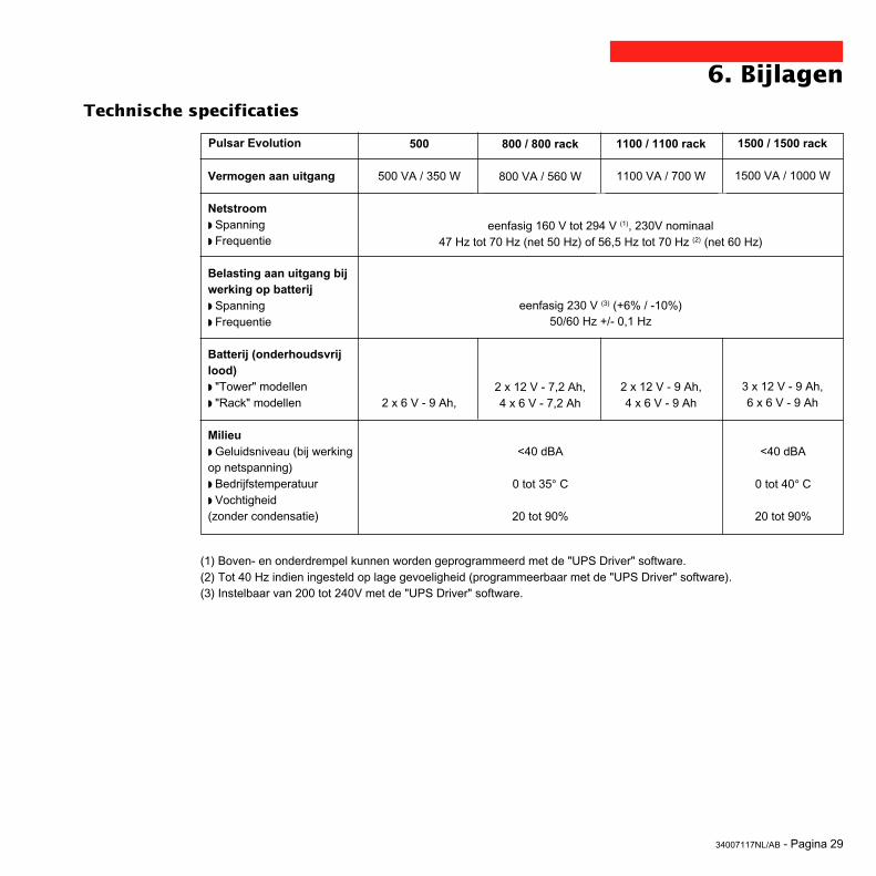
34007117NL/AB - Pagina 29
6. BijlagenTechnische specificaties
Vermogen aan uitgang
Netstroom◗ Spanning◗ Frequentie
Belasting aan uitgang bijwerking op batterij◗ Spanning◗ Frequentie
Batterij (onderhoudsvrijlood)◗ "Tower" modellen◗ "Rack" modellen
Milieu◗ Geluidsniveau (bij werkingop netspanning)◗ Bedrijfstemperatuur◗ Vochtigheid(zonder condensatie)
500
500 VA / 350 W
2 x 6 V - 9 Ah,
1100 / 1100 rack
1100 VA / 700 W
2 x 12 V - 9 Ah,4 x 6 V - 9 Ah
(1) Boven- en onderdrempel kunnen worden geprogrammeerd met de "UPS Driver" software.(2) Tot 40 Hz indien ingesteld op lage gevoeligheid (programmeerbaar met de "UPS Driver" software).(3) Instelbaar van 200 tot 240V met de "UPS Driver" software.
800 / 800 rack
800 VA / 560 W
2 x 12 V - 7,2 Ah,4 x 6 V - 7,2 Ah
1500 / 1500 rack
1500 VA / 1000 W
3 x 12 V - 9 Ah,6 x 6 V - 9 Ah
Pulsar Evolution
eenfasig 160 V tot 294 V (1), 230V nominaal
eenfasig 230 V (3) (+6% / -10%)50/60 Hz +/- 0,1 Hz
<40 dBA
0 tot 35° C
20 tot 90%
<40 dBA
0 tot 40° C
20 tot 90%
47 Hz tot 70 Hz (net 50 Hz) of 56,5 Hz tot 70 Hz (2) (net 60 Hz)

Pagina 30 - 34007117NL/AB
6. BijlagenVoorbeelden van batterij-autonomie
Pulsar Evolution 500
Pulsar Evolution 800
Pulsar Evolution 1100
1 hub
1 router
Pulsar Evolution 1500
2 geoptimaliseerde rack servers
2 printerbestand servers
1 server + 1 router + 1 hub
0 10 20 50 100 t (min)30 40 60 70 80 90 110 120
0 10 20 50 100 t (min)30 40 60 70 80 90 110 120
0 10 20 50 100 t (min)30 40 60 70 80 90 110 120
0 10 20 50 100 t (min)30 40 60 70 80 90 110 120
1 hub
1 router
3 geoptimaliseerde rack servers
2 printerbestand servers
1 server + 1 router + 1 hub
1 hub
1 router
3 geoptimaliseerde rack servers
5 geoptimaliseerde rack servers
3 printerbestand servers
2 servers + 1 router + 1 hub
1 hub
34007117NL/AB - Pagina 31
6. Bijlagen
6.2 WoordenlijstAansluitingen aan de uitgang Pulsar Evolution heeft 2 niet programmeerbare aansluitingen aan de uitgang.
Apparatuur Apparaten of systemen die op de uitgangen van de UPS zijn aangesloten.
Autonomie Werkingsduur op batterij wanneer de netspanning niet beschikbaar is.
"Booster" functie Automatische bedrijfstoestand van de UPS waarmee de netspanning, als deze te laagis, verhoogd kan worden tot boven een specifiek te programmeren waarde, en ditzonder de batterij te ontladen.
Buiten spanning UPS mechanisch losgekoppeld van het netstroomcircuit.
Display Indicatie van geleverd vermogen en autonomie batterij op het bedieningspaneel.
"Fader" functie Automatische bedrijfstoestand van de UPS waarmee de netspanning, als deze te hoogis, verlaagd kan worden tot onder een specifiek te programmeren waarde, en dit zonderde batterij te ontladen.
Ingangsschakelaar Beveiliging van het netstroomcircuit tegen de fouten van de UPS.
Programmeerbare Pulsar Evolution 2 groepen met ieder 2 programmeerbare aansluitingen. Hiermee kanaansluitingen de beveiligen apparatuur per groep in- en uitgeschakeld worden. Zodoende kunnen
de diverse verbruikers sequentieel ingeschakeld worden en bij batterijbedrijf voortijdigworden uitgeschakeld om de autonomie van de primaire verbruikers te verlengen. Dezeaansluitingen kunnen geprogrammeerd worden met behulp van de Solution-Pac software op de CD-ROM die met het apparaat wordt meegeleverd.
RS232-communicatiepoort Maakt het mogelijk de UPS op een computer aan te sluiten via de seriëlecommunicatiepoort.
Solution-Pac Serie beheer-, programmeer- en beveiligingssoftware van MGE UPS SYSTEMS op deCD-ROM die bij het apparaat geleverd wordt.
Specifieke programmering Bepaalde functies van de UPS kunnen via de "UPS Driver" software worden afgestemdop specifieke behoeften.
UPS Uninterruptible Power Supply (Ononderbroken Stroomvoorziening).
UPS Driver Communicatiesoftware op de CD-ROM die bij het apparaat geleverd wordt, waarmee defabrieksprogrammering aan specifieke behoeften kan worden aangepast.
USB- communicatiepoort Maakt het mogelijk de UPS op een computer aan te sluiten via de USB-communicatiepoort.

Pagina 32 - 34007117NL/AB
6. Bijlagen
6.3 IndexAAansluitingen
Gegevensverbinding ..............................................16RS232-communicatiepoort .....................................16USB-communicatiepoort ....................................... 16
Afmetingen ....................................................................... 7Automatisch inschakelen ............................................... 20Autonomie batterij .......................................................... 30
BBatterij
Alarmgrens einde autonomie ................................. 19Einde autonomie batterij ......................................... 19Fout .......................................................................... 9Overschakelen op batterij ................................... 9, 19Recycleren ............................................................. 27Vervanging ................................................... 22-23-24
"Booster" functie ........................................................ 9, 18Buzzer ............................................................................ 19
CCommunicatiekaart .................................................... 8, 17
DDisplay ............................................................................. 9
F"Fader" functie ........................................................... 9, 18Fout UPS ......................................................................... 9
GGewicht ............................................................................ 7
IInschakelen .................................................................... 18
KKnoppen ........................................................................... 9
LLED’s ............................................................................... 9
MMilieu .............................................................................. 27
OOmgevingstemperatuur te hoog ................................... 29Overbelasting .............................................................9, 22Overschakelen op pauze ............................................... 20
Automatisch opnieuw schakelen ............................ 20
PPauze ............................................................................. 20Programmeerbare aansluitingen ................................. 8, 9
RRS232-communicatiepoort ....................................... 8, 16
SSchakelaar
Batterij- ..................................................................... 8Ingangs- ................................................................... 8
Specifieke programmering ............................................. 20Aan/Uit-functies ...................................................... 20Batterij .................................................................... 20Uitgang .................................................................. 21
TTechnische specificaties ................................................ 29
UUitschakelen van de UPS door software ....................... 20UPS Driver .................................................. 18, 19, 20, 29USB-communicatiepoort ............................................8, 16
VVeiligheid ........................................................................ 23Vervanging van batterijen ................................. 22, 23, 24
WWebsite .......................................................................... 27

340071170/AB

3400711700/AB

340071170/AB
MGE UPS SYSTEMS
140, Avenue Jean KuntzmannZIRST - Montbonnot St Martin38334 - Saint Ismier Cedex - Francewww.mgeups.com
Nothing will stop you now
3400711700-AB