MFG10549 AutoCAD Electrical's 60 in 60 -...
22
MFG10549 AutoCAD Electrical's 60 in 60 Tiffany Bachmeier Autodesk Learning Objectives • Discover Project Management Tips and Tricks • Discover Drawing Creation Tips and Tricks • Discover Customization Tips and Tricks • Discover Template Tips and Tricks Description Are you ready?...Set?...Let's GO! This is a fast-paced class designed to keep you on your toes with rapid- fire tips and tricks to help you get the most out of your time in AutoCAD Electrical software. Hold on tight, it’s going to be a wild ride! Your AU Expert Tiffany Bachmeier has been an Autodesk Consultant for the last decade. Her primary focus is as a technical consultant/instructor for AutoCAD Electrical, but she also focuses on AutoCAD, Inventor, and a variety of other products in the Autodesk family. She is an Autodesk Certified Instructor and she (and team) has won awards for developing a full line of online, live, instructor-led training classes for the Autodesk manufacturing products. Before becoming a consultant she earned her bachelor’s degree from Michigan State University (MSU) and she worked in many different industries gaining valuable CAD experience, including electrical engineering, interior design/architecture, mechanical engineering, software engineering, and she was part of MSU’s CAD Development Team. She started on AutoCAD R10 and has carried a strong passion for Autodesk products ever since. Tiffany Bachmeier, ACI AutoCAD Electrical Implementation Consultant Global Services, Amer Project Delivery Team MOBILE 248.207.7518 Autodesk, Inc. www.autodesk.com
Transcript of MFG10549 AutoCAD Electrical's 60 in 60 -...

MFG10549
AutoCAD Electrical's 60 in 60
Tiffany Bachmeier
Autodesk
Learning Objectives
• Discover Project Management Tips and Tricks
• Discover Drawing Creation Tips and Tricks
• Discover Customization Tips and Tricks
• Discover Template Tips and Tricks
Description Are you ready?...Set?...Let's GO! This is a fast-paced class designed to keep you on your toes with rapid-
fire tips and tricks to help you get the most out of your time in AutoCAD Electrical software. Hold on
tight, it’s going to be a wild ride!
Your AU Expert
Tiffany Bachmeier has been an Autodesk Consultant for the last decade. Her
primary focus is as a technical consultant/instructor for AutoCAD Electrical, but she
also focuses on AutoCAD, Inventor, and a variety of other products in the Autodesk
family. She is an Autodesk Certified Instructor and she (and team) has won awards
for developing a full line of online, live, instructor-led training classes for the
Autodesk manufacturing products. Before becoming a consultant she earned her
bachelor’s degree from Michigan State University (MSU) and she worked in many
different industries gaining valuable CAD experience, including electrical engineering, interior
design/architecture, mechanical engineering, software engineering, and she was part of MSU’s CAD
Development Team. She started on AutoCAD R10 and has carried a strong passion for Autodesk products
ever since.
Tiffany Bachmeier, ACI
AutoCAD Electrical Implementation Consultant
Global Services, Amer Project Delivery Team
MOBILE 248.207.7518
Autodesk, Inc.
www.autodesk.com
Feeling the Spark for AutoCAD Electrical
(For AutoCAD Users)
2
Overview
The complete list of all 60 Tips & Tricks from this class will be available after the class (have to build up
the suspense ☺) In the meantime below are some foundational notes on AutoCAD Electrical.
Learning Objective 1: Discover Project Management Tips and Tricks
The AutoCAD Electrical Project
AutoCAD Electrical uses a project-based system to manage the multiple drawings and inter-drawing
relationships contained in most electrical projects. Understanding how this system works is essential to
increasing your efficiency and creating accurate electrical designs.
Definition of an ACADE Project File
• A project file is an ASCII text file with a .wdp extension that stores information about a
project. A project file contains some of the following information:
• Project description lines (most commonly used for automatically updating all title
blocks)
• Project default settings (design standards)
• Project drawing list, including: Complete path information, Drawing description lines,
Section and subsection assignments
• Other miscellaneous catalog and symbol library settings
• Folder structure of the project drawings
To ensure consistency throughout the project drawings, the project settings you store in the
project file are referenced when you create or add new drawings to a project. A single project
file can find an unlimited number of drawings located in many different directories (though this
is not a best practice).
By default, project files are stored in the directory pointed to by the WD_PROJ setting in your
environment file (defined during installation), but the project files can be stored in any
subdirectory. The location of the project file is used early in the file search path. Custom drawing
files, symbol libraries, and other reference files can be stored in the project directory so that you
can easily change configurations for different project needs.
Relative Drawing File Paths
Relative path information is used to save the drawing file location. If the drawing is stored in the
same directory as the project file, only the file name is stored in the project file. If the drawing is
stored in a different directory than the project file, the drawing name information includes both
the file name and complete relative path information.
Feeling the Spark for AutoCAD Electrical
(For AutoCAD Users)
3
Note: Absolute or fixed paths to drawing files can also be used. To use an absolute path to a
drawing file, you must manually edit the project file using any text editor. You cannot enter a
fixed path using the project manager.
Guidelines for Project Files
Follow these guidelines when working with project files:
• A single project file can have drawings located in many different directories. There is no
limit to the number of drawings in a project.
o The recommended location for the project file is in the same directory as the
project drawing files. Although this is not required, it allows the project to be
moved to different directories or entered into file management programs, such
as Autodesk® Vault, with little or no management of file paths.
• Although you can use any text editor to edit a project file, in most cases it is
recommended that you use the Project Manager to make changes.
• When archiving or backing up the project drawing files, it is important to include the
project file.
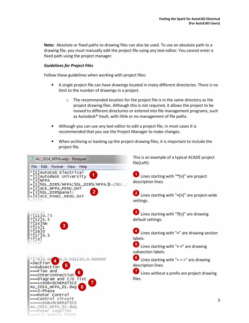
This is an example of a typical ACADE project
file(Left):
Lines starting with "*[n]" are project
description lines.
Lines starting with "+[n]" are project-wide
settings.
Lines starting with "?[n]" are drawing
default settings.
Lines starting with "=" are drawing section
labels.
Lines starting with "= =" are drawing
subsection labels.
Lines starting with "= = =" are drawing
description lines.
Lines without a prefix are project drawing
files.
Feeling the Spark for AutoCAD Electrical
(For AutoCAD Users)
4
A project drawing file that is stored in the same directory as the project file. Only
the drawing file name is listed.
TIPS:
• A project file is not needed if the project consists of a single drawing.
• For more details on what is contained in a project file, go to AutoCAD Electrical Help >
Projects and Drawings
Learning Objective 2: Discover Drawing Creation Tips and Tricks
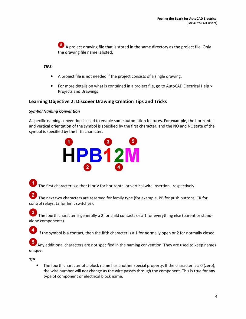
Symbol Naming Convention
A specific naming convention is used to enable some automation features. For example, the horizontal
and vertical orientation of the symbol is specified by the first character, and the NO and NC state of the
symbol is specified by the fifth character.
The first character is either H or V for horizontal or vertical wire insertion, respectively.
The next two characters are reserved for family type (for example, PB for push buttons, CR for
control relays, LS for limit switches).
The fourth character is generally a 2 for child contacts or a 1 for everything else (parent or stand-
alone components).
If the symbol is a contact, then the fifth character is a 1 for normally open or 2 for normally closed.
Any additional characters are not specified in the naming convention. They are used to keep names
unique.
TIP
• The fourth character of a block name has another special property. If the character is a 0 (zero),
the wire number will not change as the wire passes through the component. This is true for any
type of component or electrical block name.
Feeling the Spark for AutoCAD Electrical
(For AutoCAD Users)
5
Symbol Attributes
Attributes are objects that are included in a block definition to store alphanumeric data and are the
primary data storage on schematic and panel symbols. Attributes are especially useful on schematic
symbols because they are very consistent. One schematic symbol can represent many different
manufacturers and part numbers.
To be treated as an electrical symbol, a schematic symbol must have an attribute named either TAG1 for
a parent symbol, or TAG2 for a child symbol, associated with it. Though they are very important for Bill
of Material data, wire connections, and other electrical functions and data storage, all other attributes
are optional.
TAG1 Attribute
On a parent or stand-alone component, the TAG1 attribute is used for the component tag name
or unique identifier, for example, PB101 or CR-55. The default value assigned to this attribute
definition is used as the Family Code (%F) portion of the tag format code as set in the drawing
configuration. If the TAG1 attribute carries no default value, then the symbol's FAMILY attribute
value is used.
Note: You can override the family name at insertion, during a later edit, or automatically by
using the wd_fam.dat mapping file. For more information, see AutoCAD Electrical Help. On the
Index tab, type wd_fam.dat
TAG2 Attribute
On a child component, the TAG2 attribute is used for the component tag name. When a child
component is linked to its parent, the value of the TAG2 attribute is copied from the TAG1
attribute of the parent component. If the child component is not linked to a parent, the default
value of TAG2 is displayed.
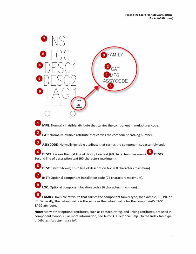
Other Standard ACADE Attributes
The attributes displayed below are standard attributes and they are typical for any schematic
symbols. These attributes are optional, but they are commonly used in both parent and child
components.
Feeling the Spark for AutoCAD Electrical
(For AutoCAD Users)
6
MFG: Normally invisible attribute that carries the component manufacturer code.
CAT: Normally invisible attribute that carries the component catalog number.
ASSYCODE: Normally invisible attribute that carries the component subassembly code.
DESC1: Carries the first line of description text (60 characters maximum). DESC2:
Second line of description text (60 characters maximum).
DESC3: (Not Shown) Third line of description text (60 characters maximum).
INST: Optional component installation code (24 characters maximum).
LOC: Optional component location code (16 characters maximum).
FAMILY: Invisible attribute that carries the component family type, for example, CR, PB, or
LT. Generally, the default value is the same as the default value for the component's TAG1 or
TAG2 attribute.
Note: Many other optional attributes, such as contact, rating, and linking attributes, are used in
component symbols. For more information, see AutoCAD Electrical Help. On the Index tab, type
attributes, for schematics (all)
Feeling the Spark for AutoCAD Electrical
(For AutoCAD Users)
7
TIP
• If you need to separate the tag value into two separate lines, you use split TAG
attributes: TAG1_PART1 and TAG1_PART2 for the parent, and TAG2_PART1 and
TAG2_PART2 for the child components. For more information, see AutoCAD Electrical
Help. On the Index tab, type split tags
Learning Objective 3: Discover Customization Tips and Tricks
Various reference files are supported by AutoCAD Electrical to help annotate your drawings. ASCII text
files are used as reference files for many different purposes. Only a few of the more frequently used files
are briefly explained here.
Knowledge of these files, how they are used, and how they can be made project-specific can help make
tasks, such as changing drawing descriptions or mapping title block attributes, easier to understand and
complete and when they are customized to your company’s needs, they set the foundation for everyone
creating these drawings to follow the same standards.
Component Reference Files
Description (wd_desc.wdd), installation (default.inst), and location (default.loc) files are generic ASCII
text files that contain either common values or your company's standard nomenclature for these fields.
Instead of reentering values for each field, you can select the entry from a list.
You can use wizards in the software, or any external text editor, such as Notepad, to edit these files.
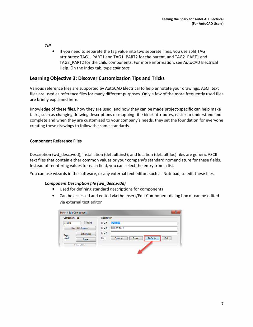
Component Description file (wd_desc.wdd)
• Used for defining standard descriptions for components
• Can be accessed and edited via the Insert/Edit Component dialog box or can be edited
via external text editor
Feeling the Spark for AutoCAD Electrical
(For AutoCAD Users)
8
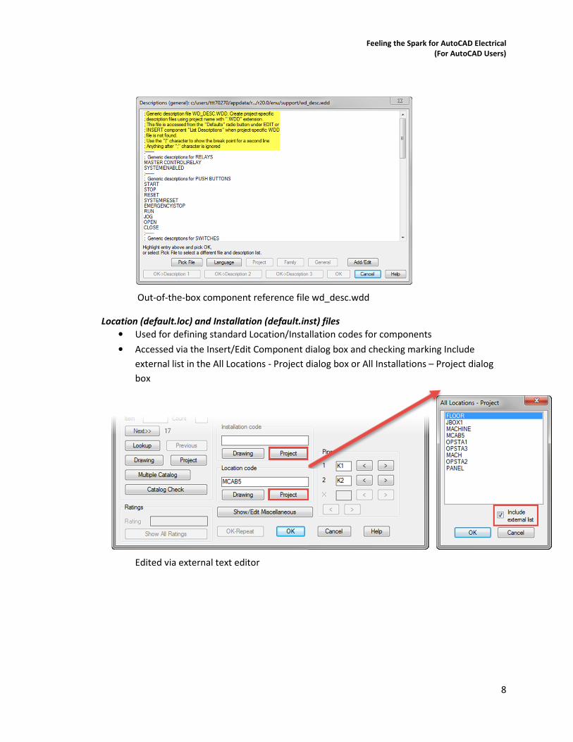
Out-of-the-box component reference file wd_desc.wdd
Location (default.loc) and Installation (default.inst) files
• Used for defining standard Location/Installation codes for components
• Accessed via the Insert/Edit Component dialog box and checking marking Include
external list in the All Locations - Project dialog box or All Installations – Project dialog
box
Edited via external text editor
Feeling the Spark for AutoCAD Electrical
(For AutoCAD Users)
9
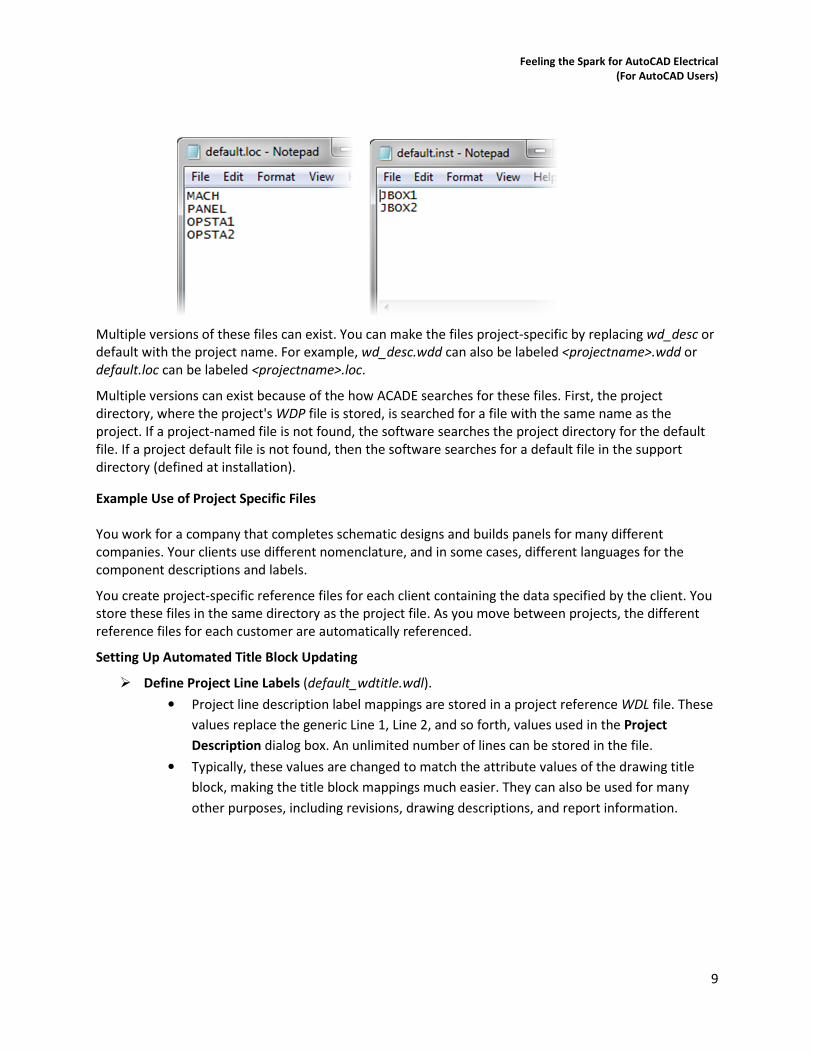
Multiple versions of these files can exist. You can make the files project-specific by replacing wd_desc or
default with the project name. For example, wd_desc.wdd can also be labeled <projectname>.wdd or
default.loc can be labeled <projectname>.loc.
Multiple versions can exist because of the how ACADE searches for these files. First, the project
directory, where the project's WDP file is stored, is searched for a file with the same name as the
project. If a project-named file is not found, the software searches the project directory for the default
file. If a project default file is not found, then the software searches for a default file in the support
directory (defined at installation).
Example Use of Project Specific Files
You work for a company that completes schematic designs and builds panels for many different
companies. Your clients use different nomenclature, and in some cases, different languages for the
component descriptions and labels.
You create project-specific reference files for each client containing the data specified by the client. You
store these files in the same directory as the project file. As you move between projects, the different
reference files for each customer are automatically referenced.
Setting Up Automated Title Block Updating
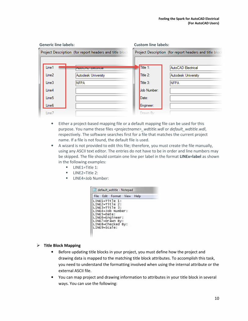
� Define Project Line Labels (default_wdtitle.wdl).
• Project line description label mappings are stored in a project reference WDL file. These
values replace the generic Line 1, Line 2, and so forth, values used in the Project
Description dialog box. An unlimited number of lines can be stored in the file.
• Typically, these values are changed to match the attribute values of the drawing title
block, making the title block mappings much easier. They can also be used for many
other purposes, including revisions, drawing descriptions, and report information.
Feeling the Spark for AutoCAD Electrical
(For AutoCAD Users)
10
Generic line labels: Custom line labels:
• Either a project-based mapping file or a default mapping file can be used for this
purpose. You name these files <projectname>_wdtitle.wdl or default_wdtitle.wdl,
respectively. The software searches first for a file that matches the current project
name. If a file is not found, the default file is used.
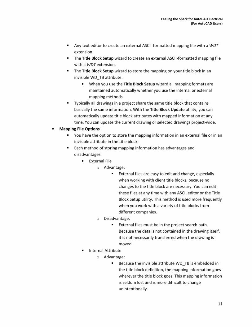
• A wizard is not provided to edit this file; therefore, you must create the file manually,
using any ASCII text editor. The entries do not have to be in order and line numbers may
be skipped. The file should contain one line per label in the format LINEx=label as shown
in the following examples:
� LINE1=Title 1:
� LINE2=Title 2:
� LINE4=Job Number:
� Title Block Mapping
• Before updating title blocks in your project, you must define how the project and
drawing data is mapped to the matching title block attributes. To accomplish this task,
you need to understand the formatting involved when using the internal attribute or the
external ASCII file.
• You can map project and drawing information to attributes in your title block in several
ways. You can use the following:
Feeling the Spark for AutoCAD Electrical
(For AutoCAD Users)
11
� Any text editor to create an external ASCII-formatted mapping file with a WDT
extension.
� The Title Block Setup wizard to create an external ASCII-formatted mapping file
with a WDT extension.
� The Title Block Setup wizard to store the mapping on your title block in an
invisible WD_TB attribute.
• When you use the Title Block Setup wizard all mapping formats are
maintained automatically whether you use the internal or external
mapping methods.
� Typically all drawings in a project share the same title block that contains
basically the same information. With the Title Block Update utility, you can
automatically update title block attributes with mapped information at any
time. You can update the current drawing or selected drawings project-wide.
• Mapping File Options
� You have the option to store the mapping information in an external file or in an
invisible attribute in the title block.
� Each method of storing mapping information has advantages and
disadvantages:
• External File
o Advantage:
� External files are easy to edit and change, especially
when working with client title blocks, because no
changes to the title block are necessary. You can edit
these files at any time with any ASCII editor or the Title
Block Setup utility. This method is used more frequently
when you work with a variety of title blocks from
different companies.
o Disadvantage:
� External files must be in the project search path.
Because the data is not contained in the drawing itself,
it is not necessarily transferred when the drawing is
moved.
• Internal Attribute
o Advantage:
� Because the invisible attribute WD_TB is embedded in
the title block definition, the mapping information goes
wherever the title block goes. This mapping information
is seldom lost and is more difficult to change
unintentionally.
Feeling the Spark for AutoCAD Electrical
(For AutoCAD Users)
12
o Disadvantage:
� Because internal attributes are stored in title block
definitions, title blocks must be exploded to edit these
attributes' mappings with the Title Block Setup utility.
You can manually edit the mappings, without exploding
the block, using an attribute editing command. This
method is used more frequently with internal title
blocks that change less frequently.
� Tip: You can also use a combination of both methods. If available on a title
block, an internal attribute is used first. If the internal attribute is not found, the
default search path is used to locate an external mapping file.
• External File Options
� When using an external title block update mapping file, you have three file
options to choose from:
• <Projectname>.wdt: Has the same name as the active project and is
stored in the active project directory. Used only for the project title
blocks.
• Default.wdt: Stored in the current project directory. If a project-specific
file (<projectname>.wdt) is not available, this file is used for any project
in the same directory.
• Default.wdt: Final option, located in the search path. Used if either the
<projectname>.wdt or default.wdp file cannot be located in the active
project directory.
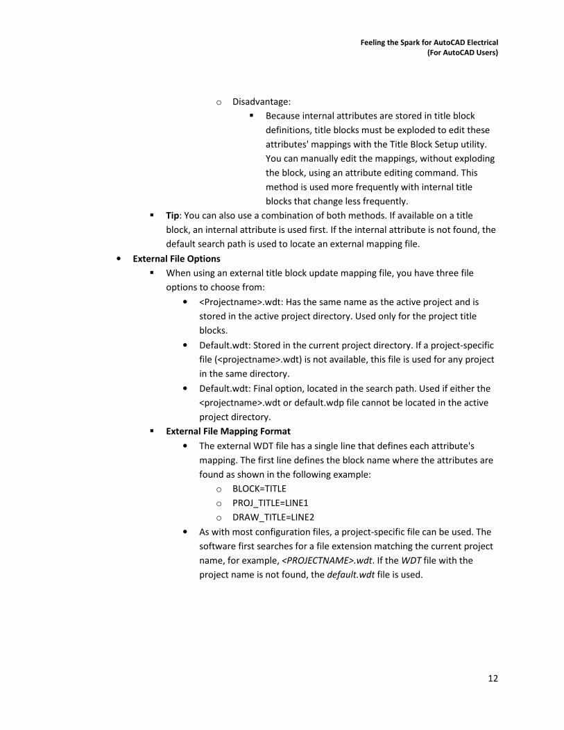
� External File Mapping Format
• The external WDT file has a single line that defines each attribute's
mapping. The first line defines the block name where the attributes are
found as shown in the following example:
o BLOCK=TITLE
o PROJ_TITLE=LINE1
o DRAW_TITLE=LINE2
• As with most configuration files, a project-specific file can be used. The
software first searches for a file extension matching the current project
name, for example, <PROJECTNAME>.wdt. If the WDT file with the
project name is not found, the default.wdt file is used.
Feeling the Spark for AutoCAD Electrical
(For AutoCAD Users)
13
Example of external project specific WDT file
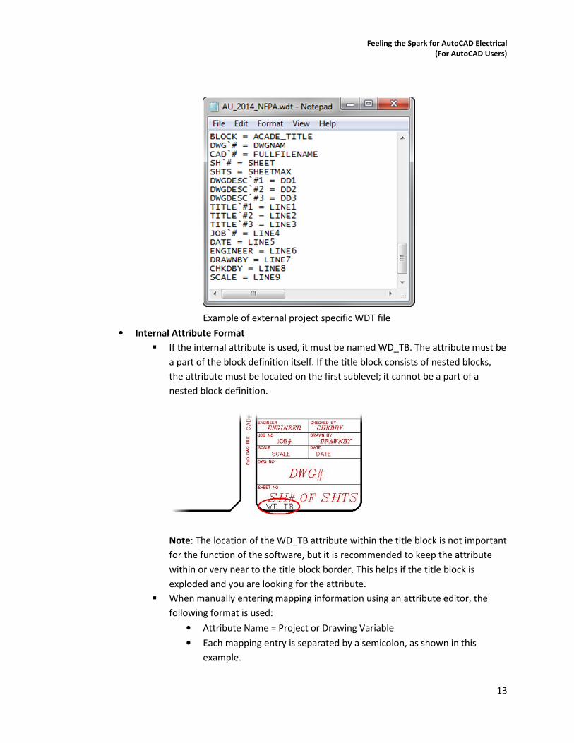
• Internal Attribute Format
� If the internal attribute is used, it must be named WD_TB. The attribute must be
a part of the block definition itself. If the title block consists of nested blocks,
the attribute must be located on the first sublevel; it cannot be a part of a
nested block definition.
Note: The location of the WD_TB attribute within the title block is not important
for the function of the software, but it is recommended to keep the attribute
within or very near to the title block border. This helps if the title block is
exploded and you are looking for the attribute.
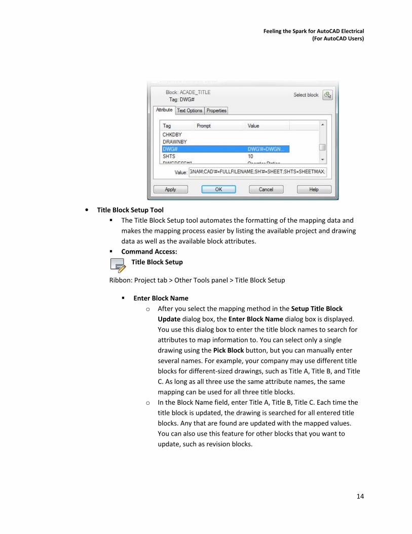
� When manually entering mapping information using an attribute editor, the
following format is used:
• Attribute Name = Project or Drawing Variable
• Each mapping entry is separated by a semicolon, as shown in this
example.
Feeling the Spark for AutoCAD Electrical
(For AutoCAD Users)
14
• Title Block Setup Tool
� The Title Block Setup tool automates the formatting of the mapping data and
makes the mapping process easier by listing the available project and drawing
data as well as the available block attributes.
� Command Access:
Title Block Setup
Ribbon: Project tab > Other Tools panel > Title Block Setup
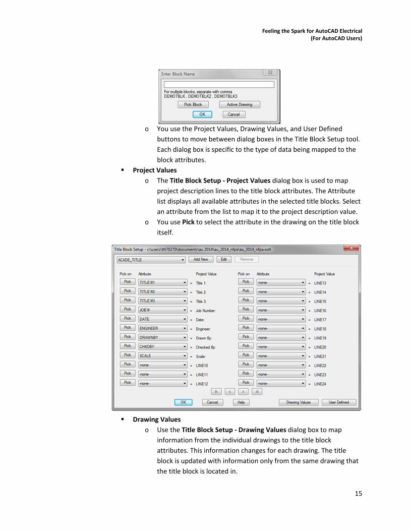
� Enter Block Name
o After you select the mapping method in the Setup Title Block
Update dialog box, the Enter Block Name dialog box is displayed.
You use this dialog box to enter the title block names to search for
attributes to map information to. You can select only a single
drawing using the Pick Block button, but you can manually enter
several names. For example, your company may use different title
blocks for different-sized drawings, such as Title A, Title B, and Title
C. As long as all three use the same attribute names, the same
mapping can be used for all three title blocks.
o In the Block Name field, enter Title A, Title B, Title C. Each time the
title block is updated, the drawing is searched for all entered title
blocks. Any that are found are updated with the mapped values.
You can also use this feature for other blocks that you want to
update, such as revision blocks.
Feeling the Spark for AutoCAD Electrical
(For AutoCAD Users)
15
o You use the Project Values, Drawing Values, and User Defined
buttons to move between dialog boxes in the Title Block Setup tool.
Each dialog box is specific to the type of data being mapped to the
block attributes.
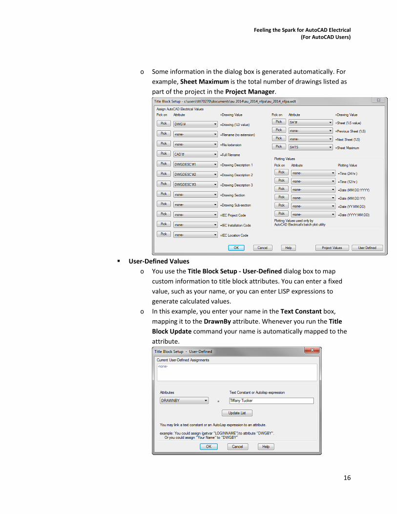
� Project Values
o The Title Block Setup - Project Values dialog box is used to map
project description lines to the title block attributes. The Attribute
list displays all available attributes in the selected title blocks. Select
an attribute from the list to map it to the project description value.
o You use Pick to select the attribute in the drawing on the title block
itself.
� Drawing Values
o Use the Title Block Setup - Drawing Values dialog box to map
information from the individual drawings to the title block
attributes. This information changes for each drawing. The title
block is updated with information only from the same drawing that
the title block is located in.
Feeling the Spark for AutoCAD Electrical
(For AutoCAD Users)
16
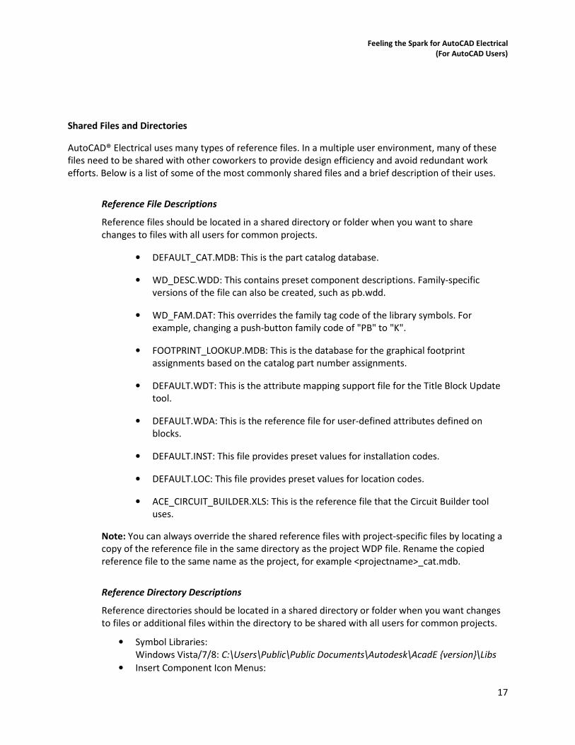
o Some information in the dialog box is generated automatically. For
example, Sheet Maximum is the total number of drawings listed as
part of the project in the Project Manager.
� User-Defined Values
o You use the Title Block Setup - User-Defined dialog box to map
custom information to title block attributes. You can enter a fixed
value, such as your name, or you can enter LISP expressions to
generate calculated values.
o In this example, you enter your name in the Text Constant box,
mapping it to the DrawnBy attribute. Whenever you run the Title
Block Update command your name is automatically mapped to the
attribute.
Feeling the Spark for AutoCAD Electrical
(For AutoCAD Users)
17
Shared Files and Directories
AutoCAD® Electrical uses many types of reference files. In a multiple user environment, many of these
files need to be shared with other coworkers to provide design efficiency and avoid redundant work
efforts. Below is a list of some of the most commonly shared files and a brief description of their uses.
Reference File Descriptions
Reference files should be located in a shared directory or folder when you want to share
changes to files with all users for common projects.
• DEFAULT_CAT.MDB: This is the part catalog database.
• WD_DESC.WDD: This contains preset component descriptions. Family-specific
versions of the file can also be created, such as pb.wdd.
• WD_FAM.DAT: This overrides the family tag code of the library symbols. For
example, changing a push-button family code of "PB" to "K".
• FOOTPRINT_LOOKUP.MDB: This is the database for the graphical footprint
assignments based on the catalog part number assignments.
• DEFAULT.WDT: This is the attribute mapping support file for the Title Block Update
tool.
• DEFAULT.WDA: This is the reference file for user-defined attributes defined on
blocks.
• DEFAULT.INST: This file provides preset values for installation codes.
• DEFAULT.LOC: This file provides preset values for location codes.
• ACE_CIRCUIT_BUILDER.XLS: This is the reference file that the Circuit Builder tool
uses.
Note: You can always override the shared reference files with project-specific files by locating a
copy of the reference file in the same directory as the project WDP file. Rename the copied
reference file to the same name as the project, for example <projectname>_cat.mdb.
Reference Directory Descriptions
Reference directories should be located in a shared directory or folder when you want changes
to files or additional files within the directory to be shared with all users for common projects.
• Symbol Libraries:
Windows Vista/7/8: C:\Users\Public\Public Documents\Autodesk\AcadE {version}\Libs
• Insert Component Icon Menus:
Feeling the Spark for AutoCAD Electrical
(For AutoCAD Users)
18
Windows Vista/7/8: C:\Users\{username}\AppData\Roaming\Autodesk\AutoCAD
Electrical {version}\{release}\{country code}\Support
• Icon Menu Slide Images:
Windows Vista/7/8: C:\Users\{username}\AppData\Roaming\Autodesk\AutoCAD
Electrical {version}\{release}\{country code}\Support
• Catalog databases and PLC Database and Images:
Windows Vista: C:\Users\{username}\Documents\AcadE {version}\
Windows 7/8: C:\Users\{username}\Documents\Acade {version}\AeData\ en-US\
TIPS
• For the detailed listings of all the project-related files, see AutoCAD Electrical Help. The
topic is located at the Index tab, type Project Related Files
• Only some of the more commonly shared folders are listed here. For more detailed
listings of shared files, including recommended edits to the wd.env file, see AutoCAD
Electrical Help. The topic is located at the Contents tab > Advanced Productivity > Set Up
AutoCAD Electrical for Multiple Users.
Learning Objective 4: Discover Template Tips and Tricks
Drawing templates are extremely helpful in situations where you need to create your drawings with
predefined drawing standards, such as layers and drawing properties. Using drawing templates enables
you to save the time that you would have to otherwise spend in setting the required standards every
time you begin a drawing. In organizations, CAD managers create template drawings and make them
available for their team.
Definition of Drawing Templates (for AutoCAD and AutoCAD Electrical)
A drawing template is a collection of standard predefined settings, such as units, title blocks, layers, text
styles, and dimension styles, which you can use for creating many drawings. Drawing template files have
a .dwt file extension.
Drawing Templates and CAD Standards (for AutoCAD and AutoCAD Electrical)
When you work in a project in which many people are involved in creating a design, you must ensure
that all team members consistently follow the same drawing settings. Therefore, to maintain
consistency across drawings, you can establish CAD standards by sharing and using DWT files.
For creating a DWT file, you define the required drawing settings and save the file as a drawing
template. You can also save a DWT file as a drawing standard (DWS) file. You can then use a DWS file to
check and map a drawing with a drawing template for any violation of the set standards.
Preset Drawing Graphics
Templates can also include partially completed or preset drawings. These are useful when a drawing or
part of the drawing is a standard component that is frequently used in your company design projects.
Feeling the Spark for AutoCAD Electrical
(For AutoCAD Users)
19
Note: After creating a drawing that is based on a DWT file, if you modify the new drawing, the changes
do not affect the DWT file.
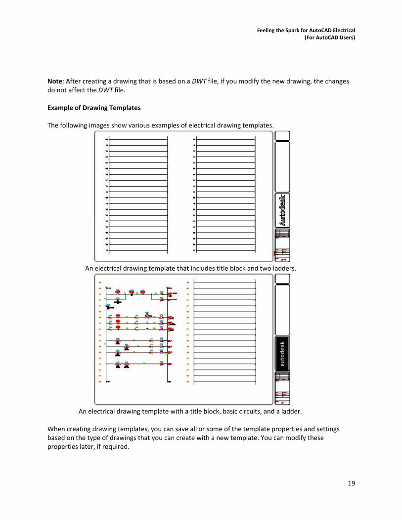
Example of Drawing Templates
The following images show various examples of electrical drawing templates.
An electrical drawing template that includes title block and two ladders.
An electrical drawing template with a title block, basic circuits, and a ladder.
When creating drawing templates, you can save all or some of the template properties and settings
based on the type of drawings that you can create with a new template. You can modify these
properties later, if required.
Feeling the Spark for AutoCAD Electrical
(For AutoCAD Users)
20
Template Properties and Settings
You use drawing templates to provide a starting point for all the new drawings that you create. In most
design environments, your drawings share some common properties and settings. When you save a
drawing template, you can save all the drawing commonalities, thereby eliminating the need to create
or adjust properties and settings each time you create a new drawing.
AutoCAD Electrical Templates
For templates created for use with AutoCAD® Electrical, it is recommended that you have the
wd_m.dwg block inserted and the drawing properties set to match the template purpose.
You can include wire layers, ladders, partial circuits, symbols, and other graphical information to provide
a preset starting drawing that matches company standards or commonly used designs.
The following are some of the properties and settings that you should save in a drawing template:
� Drawing properties settings for electrical configuration
� WD_M Block
� Wire Layers, colors, and names
� Snap and grid mode settings
� Dimension, text, and table styles
� Title blocks and borders
The following are some of the other items that you can save in a drawing template:
� Blocks, such as symbols or other objects that you commonly use in your drawings
� Ladders, circuits, and other graphical entities
Storage Location of Drawing Templates
Before you create your drawing templates, you need to specify their storage location.
Feeling the Spark for AutoCAD Electrical
(For AutoCAD Users)
21
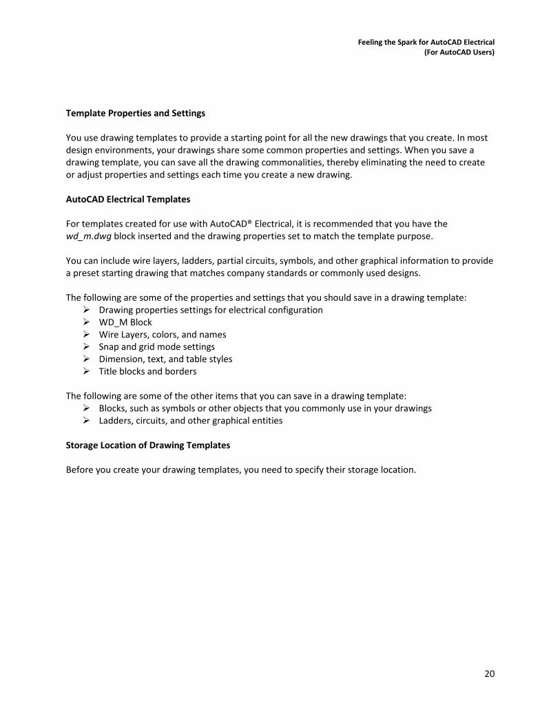
You specify the path to the DWT files on the Files tab of the Options dialog box. A path on the local hard
drive may work if you are working in a single user environment. However, if you are working as a part of
a design team, you should set the path to a network location where all project drawing templates are
consolidated.
The path that you specify as the file location of drawing templates controls the default location that
appears when you select the Drawing Template (*.dwt) format in the Files of Type list in the Save
Drawing As, Select Template, and the Select File dialog boxes.
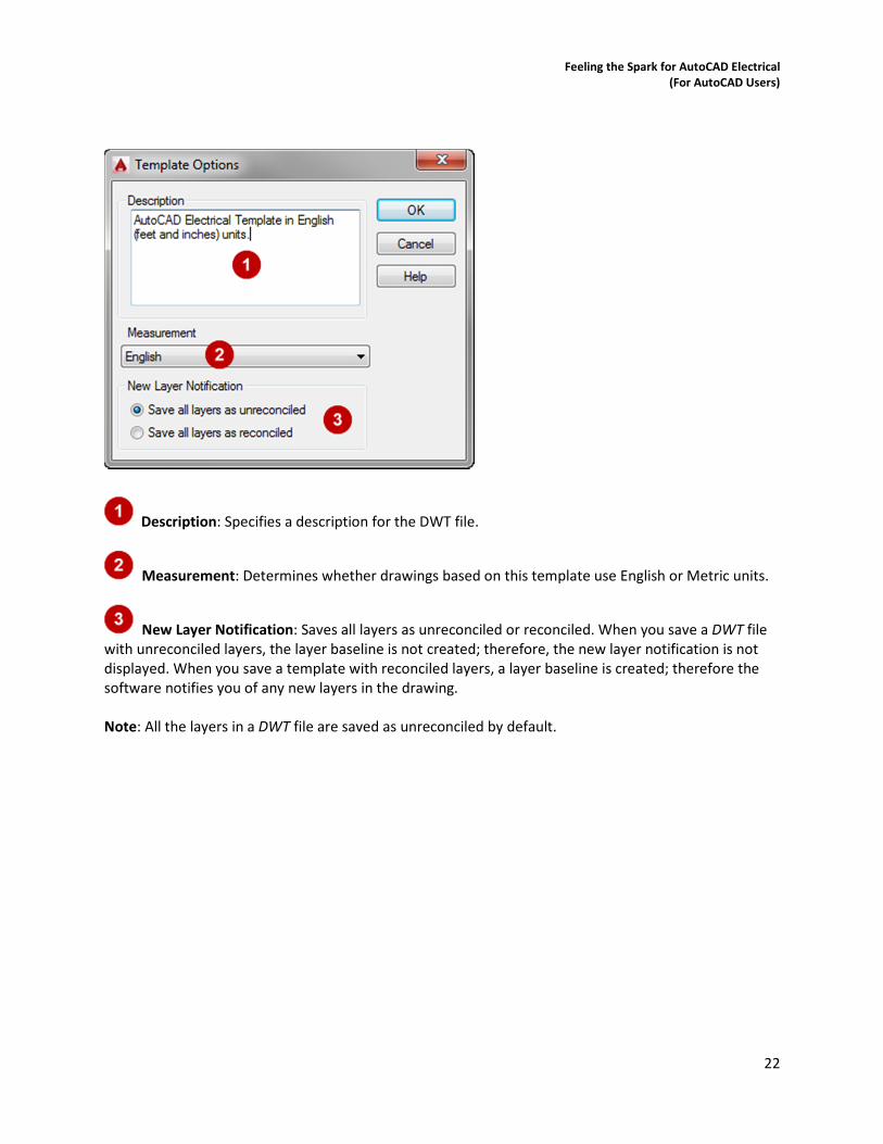
Template Options Dialog Box
By using the Template Options dialog box, you can set the drawing units to either imperial or metric,
provide a description for the template, and control new layer notification.
To access the Template Options dialog box, you select the AutoCAD Drawing Template (*.dwt) option
from the Files of Type list in the Save As dialog box.
The following image shows the Template Options dialog box.
Feeling the Spark for AutoCAD Electrical
(For AutoCAD Users)
22
Description: Specifies a description for the DWT file.
Measurement: Determines whether drawings based on this template use English or Metric units.
New Layer Notification: Saves all layers as unreconciled or reconciled. When you save a DWT file
with unreconciled layers, the layer baseline is not created; therefore, the new layer notification is not
displayed. When you save a template with reconciled layers, a layer baseline is created; therefore the
software notifies you of any new layers in the drawing.
Note: All the layers in a DWT file are saved as unreconciled by default.