
Mezzanine Analysisedge.rit.edu/edge/P17708/public/MSD2 - Phase 5/Mezzanine...1. No Live Load...
45
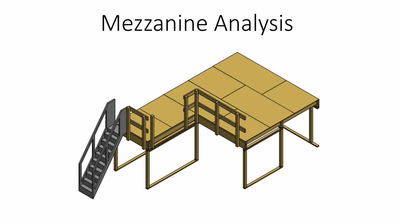
Mezzanine Analysis
Transcript of Mezzanine Analysisedge.rit.edu/edge/P17708/public/MSD2 - Phase 5/Mezzanine...1. No Live Load...
Mezzanine Analysis
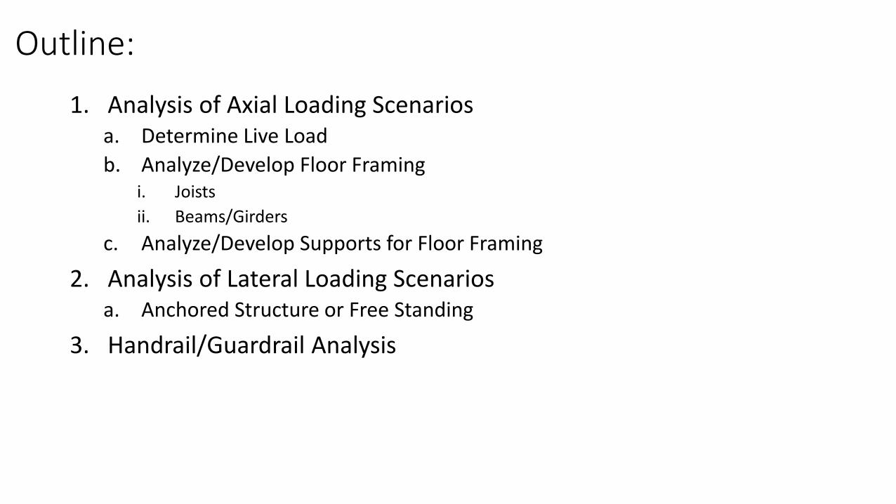
Outline:
1. Analysis of Axial Loading Scenariosa. Determine Live Load
b. Analyze/Develop Floor Framingi. Joists
ii. Beams/Girders
c. Analyze/Develop Supports for Floor Framing
2. Analysis of Lateral Loading Scenariosa. Anchored Structure or Free Standing
3. Handrail/Guardrail Analysis
Note:
• All ensuing calculations are contained within spreadsheet for easy manipulation. The analysis documented here includes numbers that are close to the final values used in decision making (but may differ slightly).
• The following analysis documents the key steps taken
• Please review the final Bill of Materials and Drawing for more precise material uses.
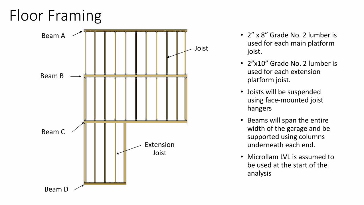
Floor Framing• 2” x 8” Grade No. 2 lumber is
used for each main platform joist.
• 2”x10” Grade No. 2 lumber is used for each extension platform joist.
• Joists will be suspended using face-mounted joist hangers
• Beams will span the entire width of the garage and be supported using columns underneath each end.
• Microllam LVL is assumed to be used at the start of the analysis
Joist
Beam A
Beam B
Beam C
Beam D
Extension Joist
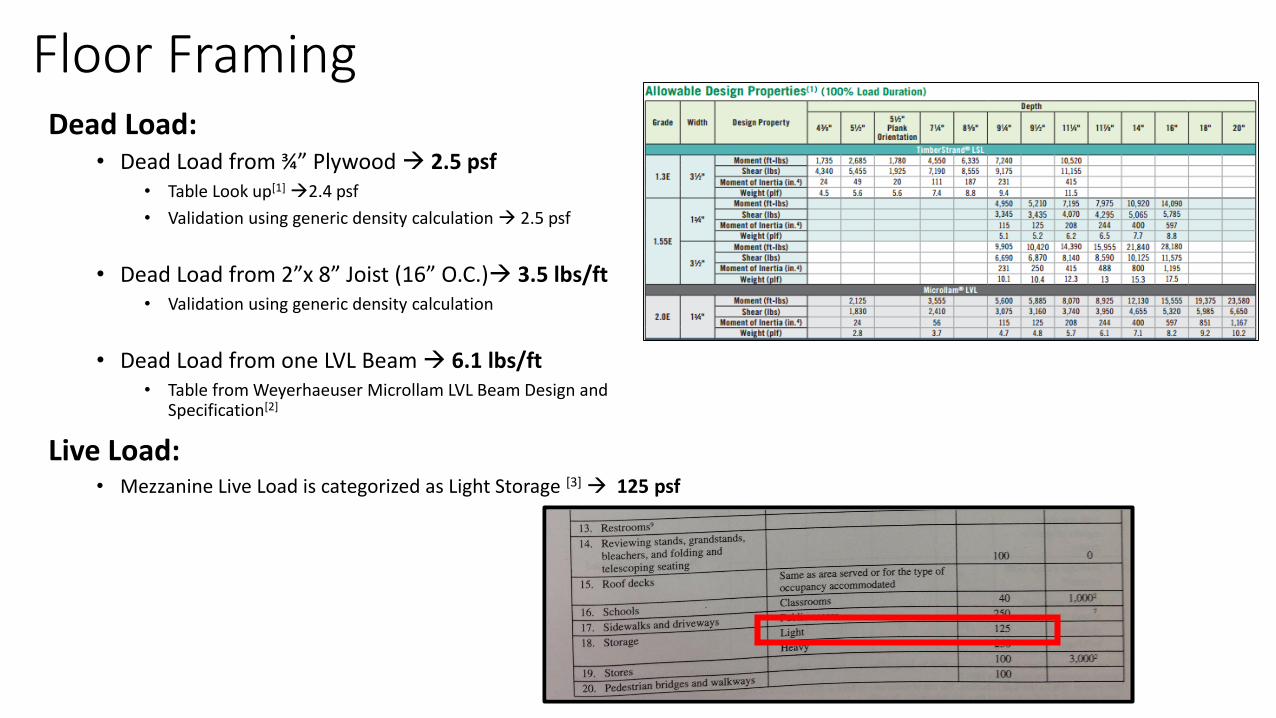
Floor FramingDead Load:
• Dead Load from ¾” Plywood 2.5 psf• Table Look up[1]
2.4 psf
• Validation using generic density calculation 2.5 psf
• Dead Load from 2”x 8” Joist (16” O.C.) 3.5 lbs/ft• Validation using generic density calculation
• Dead Load from one LVL Beam 6.1 lbs/ft• Table from Weyerhaeuser Microllam LVL Beam Design and
Specification[2]
Live Load: • Mezzanine Live Load is categorized as Light Storage [3]
125 psf
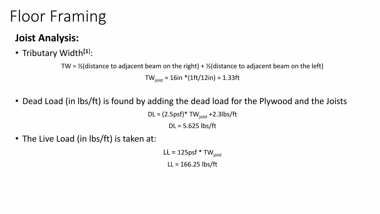
Floor FramingJoist Analysis:
• Tributary Width[1]:
TW = ½(distance to adjacent beam on the right) + ½(distance to adjacent beam on the left)
TWjoist = 16in *(1ft/12in) = 1.33ft
• Dead Load (in lbs/ft) is found by adding the dead load for the Plywood and the Joists
DL = (2.5psf)* TWjoist +2.3lbs/ft
DL = 5.625 lbs/ft
• The Live Load (in lbs/ft) is taken at:
LL = 125psf * TWjoist
LL = 166.25 lbs/ft
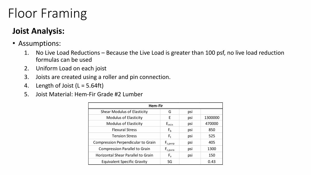
Floor FramingJoist Analysis:
• Assumptions: 1. No Live Load Reductions – Because the Live Load is greater than 100 psf, no live load reduction
formulas can be used
2. Uniform Load on each joist
3. Joists are created using a roller and pin connection.
4. Length of Joist (L = 5.64ft)
5. Joist Material: Hem-Fir Grade #2 Lumber
Shear Modulus of Elasticity G psi
Modulus of Elasticity E psi 1300000
Modulus of Elasticity Emin psi 470000
Flexural Stress Fb psi 850
Tension Stress Ft psi 525
Compression Perpendicular to Grain Fc,perp psi 405
Compression Parallel to Grain Fc,para psi 1300
Horizontal Shear Parallel to Grain Fv psi 150
Equivalent Specific Gravity SG 0.43
Hem-Fir
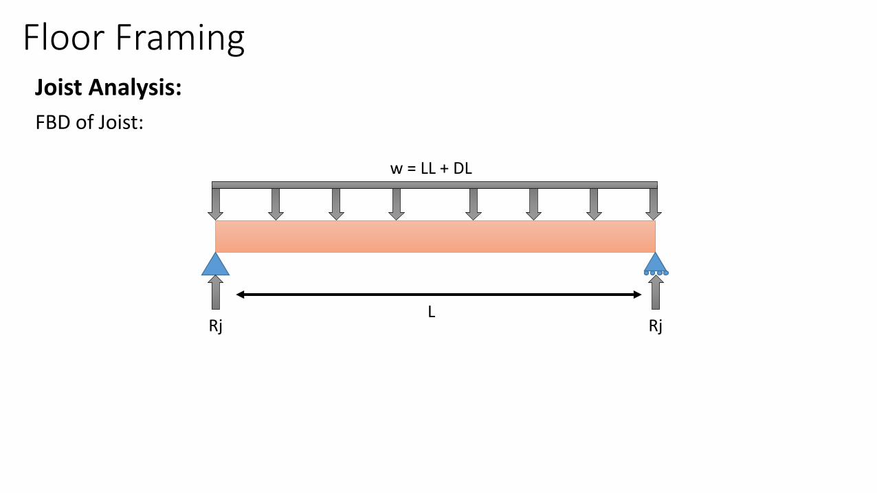
Floor FramingJoist Analysis:
FBD of Joist:
w = LL + DL
Rj RjL
Floor FramingJoist Analysis:
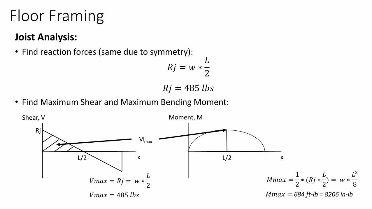
• Find reaction forces (same due to symmetry):
𝑅𝑗 = 𝑤 ∗𝐿
2
𝑅𝑗 = 485 𝑙𝑏𝑠
• Find Maximum Shear and Maximum Bending Moment:
Shear, V
Rj
L/2 L/2
Mmax
Moment, M
x x
𝑉𝑚𝑎𝑥 = 𝑅𝑗 = 𝑤 ∗𝐿
2𝑀𝑚𝑎𝑥 =
1
2∗ (𝑅𝑗 ∗
𝐿
2) = 𝑤 ∗
𝐿2
8
𝑉𝑚𝑎𝑥 = 485 𝑙𝑏𝑠 𝑀𝑚𝑎𝑥 = 684 ft-lb = 8206 in-lb
Floor FramingJoist Analysis:
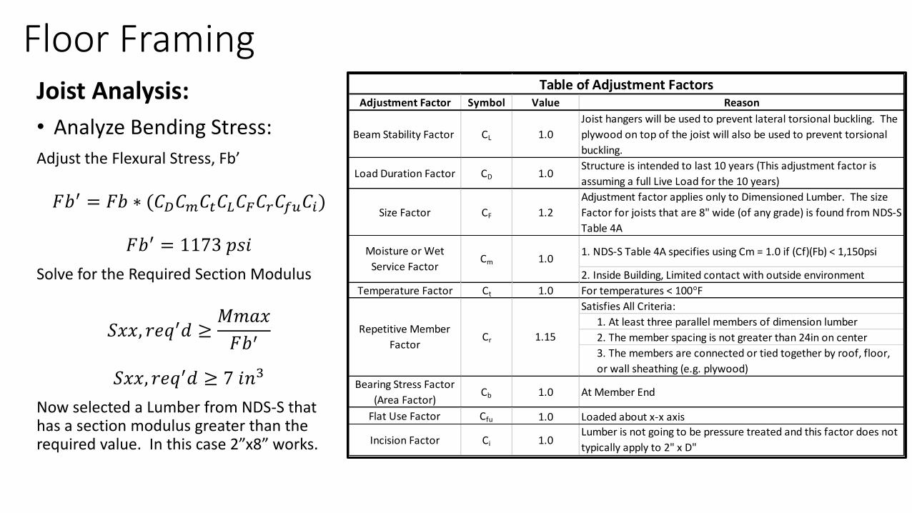
• Analyze Bending Stress:
Adjust the Flexural Stress, Fb’
𝐹𝑏′ = 𝐹𝑏 ∗ (𝐶𝐷𝐶𝑚𝐶𝑡𝐶𝐿𝐶𝐹𝐶𝑟𝐶𝑓𝑢𝐶𝑖)
𝐹𝑏′ = 1173 𝑝𝑠𝑖
Solve for the Required Section Modulus
𝑆𝑥𝑥, 𝑟𝑒𝑞′𝑑 ≥𝑀𝑚𝑎𝑥
𝐹𝑏′
𝑆𝑥𝑥, 𝑟𝑒𝑞′𝑑 ≥ 7 𝑖𝑛3
Now selected a Lumber from NDS-S that has a section modulus greater than the required value. In this case 2”x8” works.
Adjustment Factor Symbol Value Reason
Beam Stability Factor CL 1.0
Joist hangers will be used to prevent lateral torsional buckling. The
plywood on top of the joist will also be used to prevent torsional
buckling.
Load Duration Factor CD 1.0Structure is intended to last 10 years (This adjustment factor is
assuming a full Live Load for the 10 years)
Size Factor CF 1.2
Adjustment factor applies only to Dimensioned Lumber. The size
Factor for joists that are 8" wide (of any grade) is found from NDS-S
Table 4A
1. NDS-S Table 4A specifies using Cm = 1.0 if (Cf)(Fb) < 1,150psi
2. Inside Building, Limited contact with outside environment
Temperature Factor Ct 1.0 For temperatures < 100°F
Satisfies All Criteria:
1. At least three parallel members of dimension lumber
2. The member spacing is not greater than 24in on center
3. The members are connected or tied together by roof, floor,
or wall sheathing (e.g. plywood)
Bearing Stress Factor
(Area Factor)Cb 1.0 At Member End
Flat Use Factor Cfu 1.0 Loaded about x-x axis
Incision Factor Ci 1.0Lumber is not going to be pressure treated and this factor does not
typically apply to 2" x D"
Table of Adjustment Factors
Moisture or Wet
Service FactorCm 1.0
Repetitive Member
FactorCr 1.15
Floor FramingJoist Analysis:
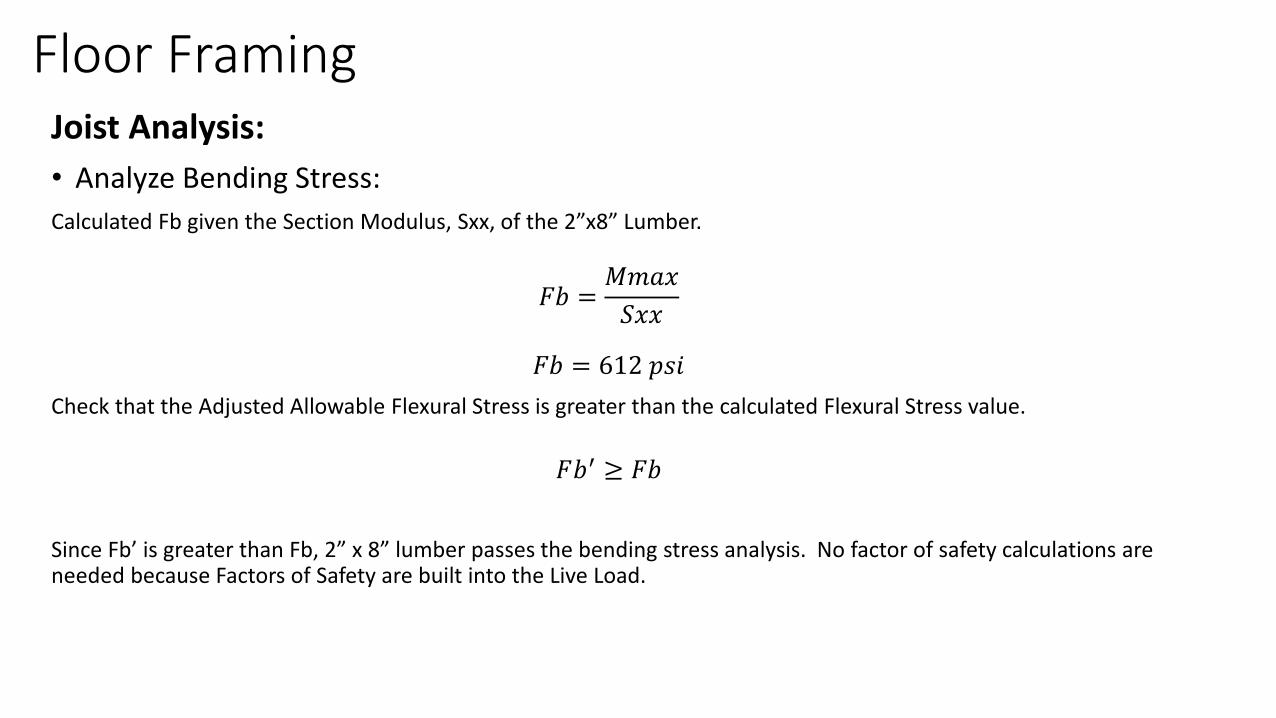
• Analyze Bending Stress:
Calculated Fb given the Section Modulus, Sxx, of the 2”x8” Lumber.
𝐹𝑏 =𝑀𝑚𝑎𝑥
𝑆𝑥𝑥
𝐹𝑏 = 612 𝑝𝑠𝑖
Check that the Adjusted Allowable Flexural Stress is greater than the calculated Flexural Stress value.
𝐹𝑏′ ≥ 𝐹𝑏
Since Fb’ is greater than Fb, 2” x 8” lumber passes the bending stress analysis. No factor of safety calculations are needed because Factors of Safety are built into the Live Load.
Floor FramingJoist Analysis:
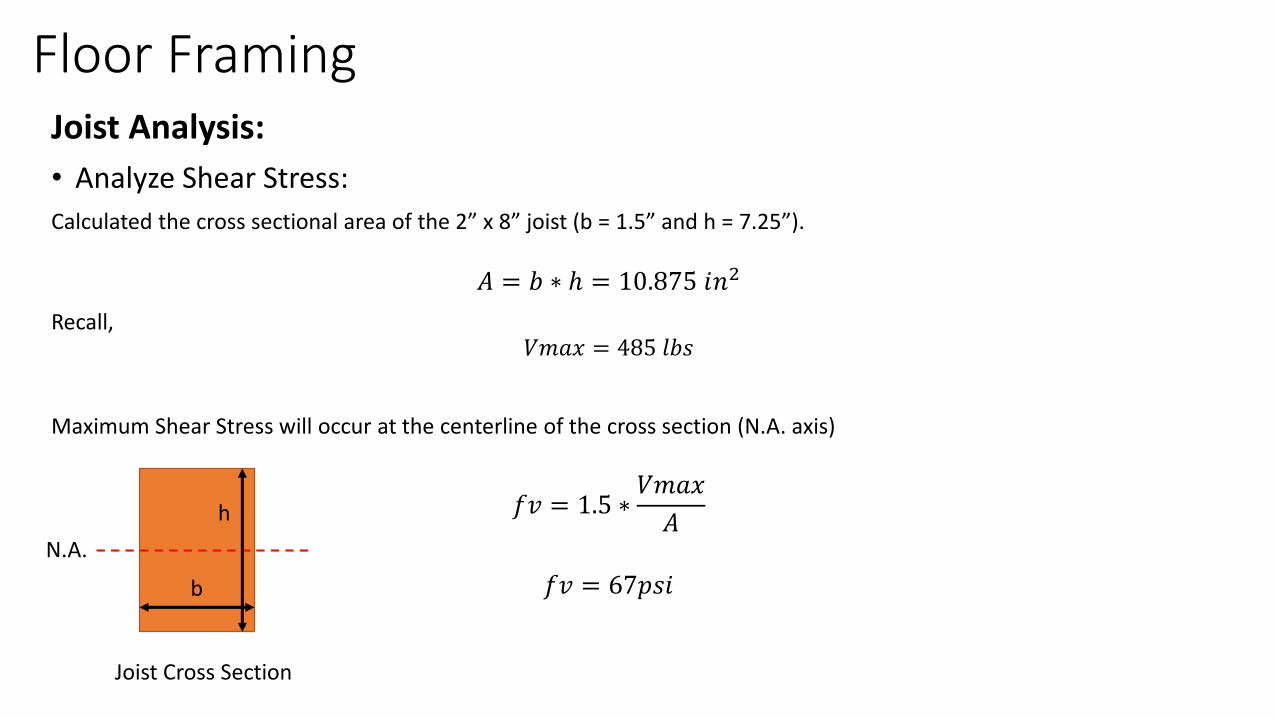
• Analyze Shear Stress:
Calculated the cross sectional area of the 2” x 8” joist (b = 1.5” and h = 7.25”).
𝐴 = 𝑏 ∗ ℎ = 10.875 𝑖𝑛2
Recall,𝑉𝑚𝑎𝑥 = 485 𝑙𝑏𝑠
Maximum Shear Stress will occur at the centerline of the cross section (N.A. axis)
𝑓𝑣 = 1.5 ∗𝑉𝑚𝑎𝑥
𝐴
𝑓𝑣 = 67𝑝𝑠𝑖
h
b
N.A.
Joist Cross Section
Floor FramingJoist Analysis:
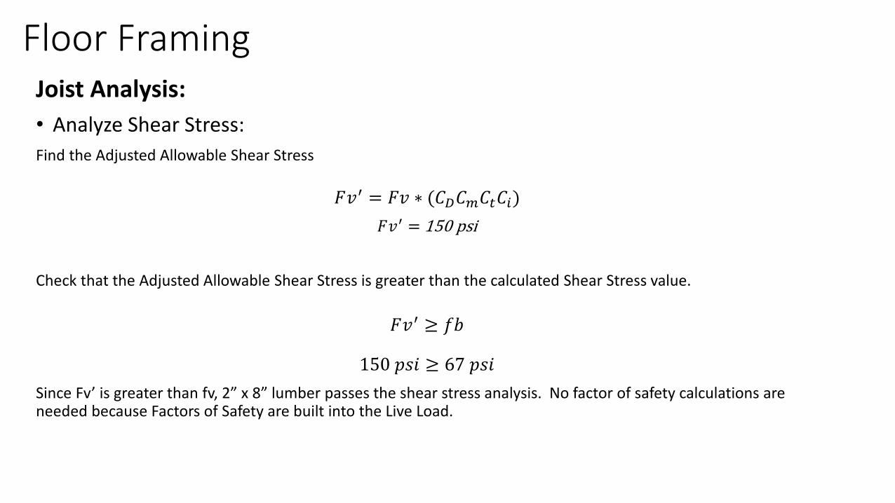
• Analyze Shear Stress:
Find the Adjusted Allowable Shear Stress
𝐹𝑣′ = 𝐹𝑣 ∗ (𝐶𝐷𝐶𝑚𝐶𝑡𝐶𝑖)
𝐹𝑣′ = 150 psi
Check that the Adjusted Allowable Shear Stress is greater than the calculated Shear Stress value.
𝐹𝑣′ ≥ 𝑓𝑏
150 𝑝𝑠𝑖 ≥ 67 𝑝𝑠𝑖
Since Fv’ is greater than fv, 2” x 8” lumber passes the shear stress analysis. No factor of safety calculations are needed because Factors of Safety are built into the Live Load.
Floor FramingJoist Analysis:
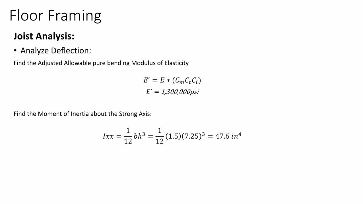
• Analyze Deflection:
Find the Adjusted Allowable pure bending Modulus of Elasticity
𝐸′ = 𝐸 ∗ (𝐶𝑚𝐶𝑡𝐶𝑖)
𝐸′ = 1,300,000psi
Find the Moment of Inertia about the Strong Axis:
𝐼𝑥𝑥 =1
12𝑏ℎ3 =
1
121.5 7.25 3 = 47.6 𝑖𝑛4
Floor FramingJoist Analysis:
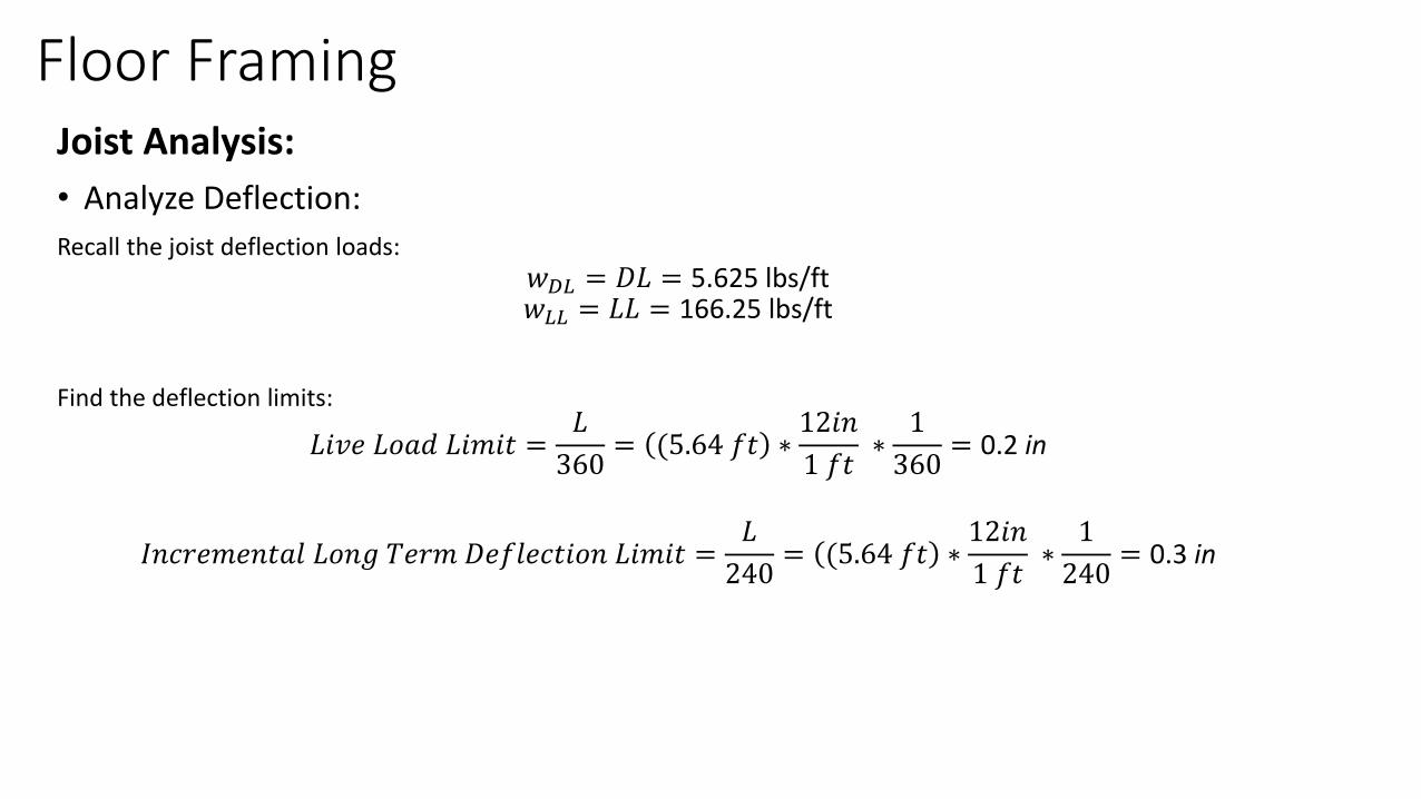
• Analyze Deflection:
Recall the joist deflection loads:𝑤𝐷𝐿 = 𝐷𝐿 = 5.625 lbs/ft𝑤𝐿𝐿 = 𝐿𝐿 = 166.25 lbs/ft
Find the deflection limits:
𝐿𝑖𝑣𝑒 𝐿𝑜𝑎𝑑 𝐿𝑖𝑚𝑖𝑡 =𝐿
360= (5.64 𝑓𝑡 ∗
12𝑖𝑛
1 𝑓𝑡∗
1
360= 0.2 in
𝐼𝑛𝑐𝑟𝑒𝑚𝑒𝑛𝑡𝑎𝑙 𝐿𝑜𝑛𝑔 𝑇𝑒𝑟𝑚 𝐷𝑒𝑓𝑙𝑒𝑐𝑡𝑖𝑜𝑛 𝐿𝑖𝑚𝑖𝑡 =𝐿
240= (5.64 𝑓𝑡 ∗
12𝑖𝑛
1 𝑓𝑡∗
1
240= 0.3 in
Floor FramingJoist Analysis:
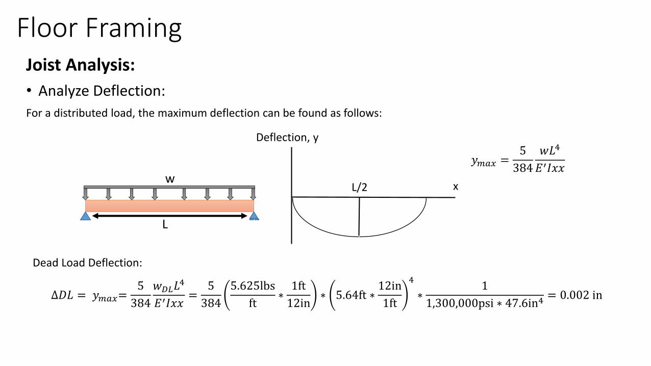
• Analyze Deflection:
For a distributed load, the maximum deflection can be found as follows:
L/2
Deflection, y
xw
L
𝑦𝑚𝑎𝑥 =5
384
𝑤𝐿4
𝐸′𝐼𝑥𝑥
Dead Load Deflection:
∆𝐷𝐿 = 𝑦𝑚𝑎𝑥=5
384
𝑤𝐷𝐿𝐿4
𝐸′𝐼𝑥𝑥=
5
384
5.625lbs
ft∗1ft
12in∗ 5.64ft ∗
12in
1ft
4
∗1
1,300,000psi ∗ 47.6in4= 0.002 in
Floor FramingJoist Analysis:
• Analyze Deflection:
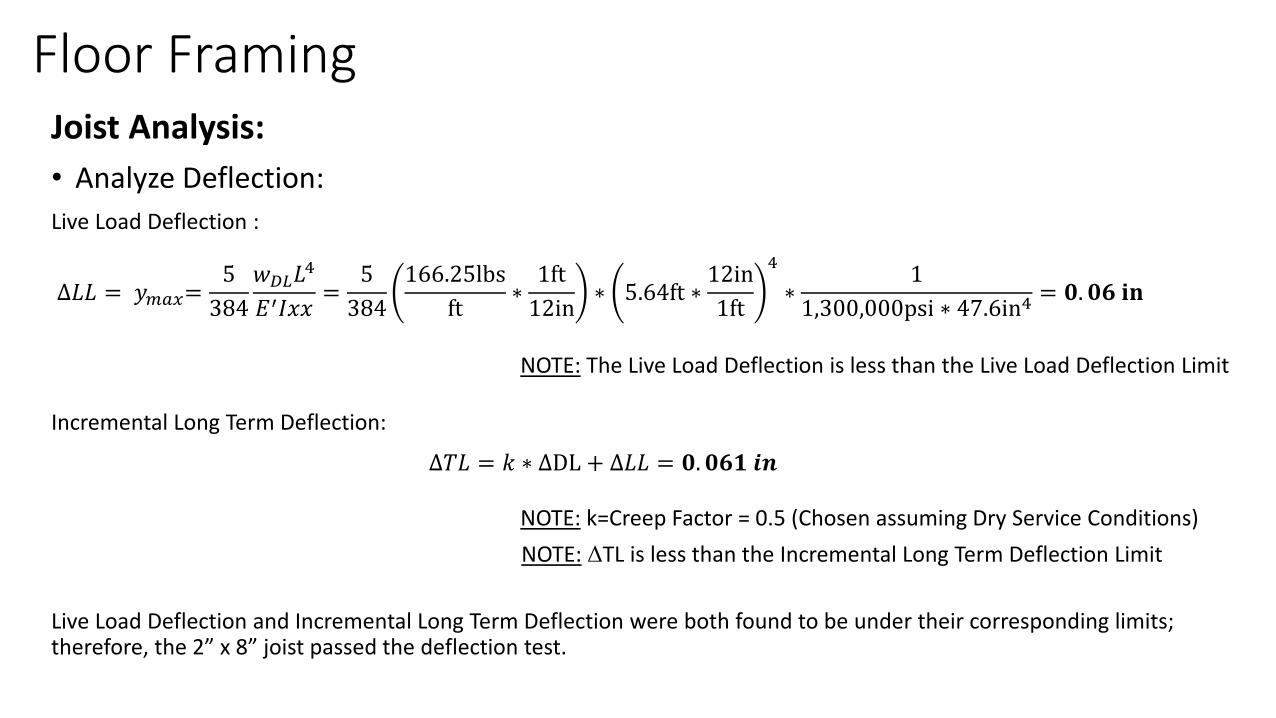
Live Load Deflection :
NOTE: The Live Load Deflection is less than the Live Load Deflection Limit
∆𝐿𝐿 = 𝑦𝑚𝑎𝑥=5
384
𝑤𝐷𝐿𝐿4
𝐸′𝐼𝑥𝑥=
5
384
166.25lbs
ft∗1ft
12in∗ 5.64ft ∗
12in
1ft
4
∗1
1,300,000psi ∗ 47.6in4= 𝟎. 𝟎𝟔 𝐢𝐧
Incremental Long Term Deflection:
∆𝑇𝐿 = 𝑘 ∗ ∆DL + ∆𝐿𝐿 = 𝟎. 𝟎𝟔𝟏 𝒊𝒏
NOTE: k=Creep Factor = 0.5 (Chosen assuming Dry Service Conditions)
NOTE: ΔTL is less than the Incremental Long Term Deflection Limit
Live Load Deflection and Incremental Long Term Deflection were both found to be under their corresponding limits; therefore, the 2” x 8” joist passed the deflection test.
Floor FramingJoist Analysis:
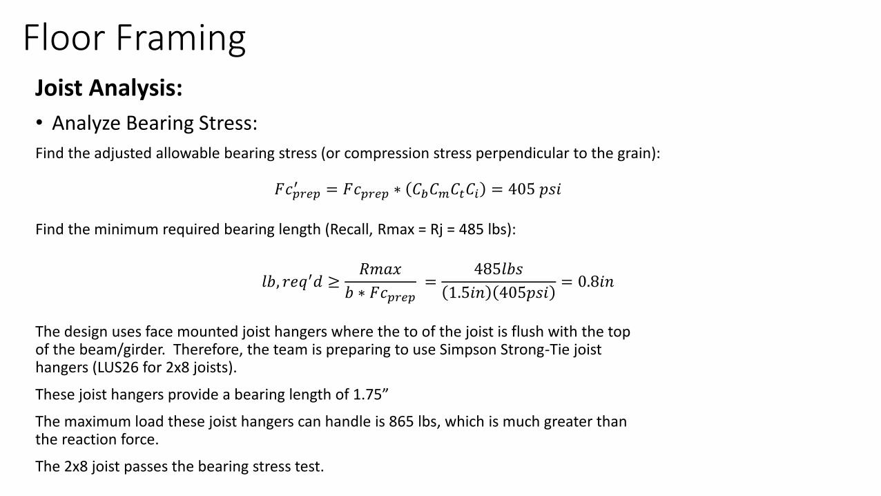
• Analyze Bearing Stress:
Find the adjusted allowable bearing stress (or compression stress perpendicular to the grain):
Find the minimum required bearing length (Recall, Rmax = Rj = 485 lbs):
The design uses face mounted joist hangers where the to of the joist is flush with the top of the beam/girder. Therefore, the team is preparing to use Simpson Strong-Tie joist hangers (LUS26 for 2x8 joists).
These joist hangers provide a bearing length of 1.75”
The maximum load these joist hangers can handle is 865 lbs, which is much greater than the reaction force.
The 2x8 joist passes the bearing stress test.
𝐹𝑐𝑝𝑟𝑒𝑝′ = 𝐹𝑐𝑝𝑟𝑒𝑝 ∗ 𝐶𝑏𝐶𝑚𝐶𝑡𝐶𝑖 = 405 𝑝𝑠𝑖
𝑙𝑏, 𝑟𝑒𝑞′𝑑 ≥𝑅𝑚𝑎𝑥
𝑏 ∗ 𝐹𝑐𝑝𝑟𝑒𝑝=
485𝑙𝑏𝑠
1.5𝑖𝑛 405𝑝𝑠𝑖= 0.8𝑖𝑛
Floor FramingJoist Analysis:
• The same procedure was conducted for the joists used on the extension portion of the platform. At 16” O.C. and a length (L) of 8ft, the joist were analysis showed that the joist were required to be at least 2”x10”.
• The 2”x10” Joist require the used of an LUS210 joist hanger to meet all the appropriate requirements.
• These conclusions can be verified using the accompanying spreadsheet which runs through the analysis.
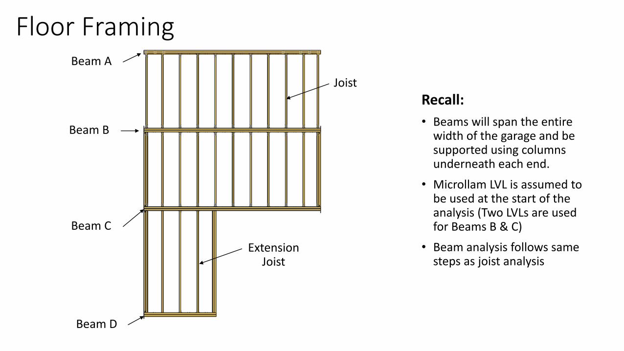
Floor Framing
Recall:
• Beams will span the entire width of the garage and be supported using columns underneath each end.
• Microllam LVL is assumed to be used at the start of the analysis (Two LVLs are used for Beams B & C)
• Beam analysis follows same steps as joist analysis
Joist
Beam A
Beam B
Beam C
Beam D
Extension Joist

Floor FramingBeam Analysis:
• Find the Maximum Shear and the Maximum Bending Moment for each BeamBeam A:
w = LL + DL
RA RAL
TWA = 70.25in *(1ft/12in) = 2.9ft
DL = (2.5psf)* TWA +2.3lbs/ft + 6.1 lbs/ft = 15.65 lbs/ft
LL = 125psf * TWA = 362.5 lbs/ft
𝑅𝐴 = 𝑤 ∗𝐿
2= 2520 𝑙𝑏𝑠
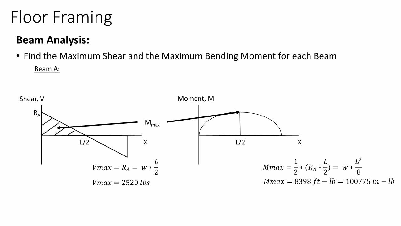
Floor FramingBeam Analysis:
• Find the Maximum Shear and the Maximum Bending Moment for each BeamBeam A:
Shear, V
RA
L/2 L/2
Mmax
Moment, M
x x
𝑉𝑚𝑎𝑥 = 𝑅𝐴 = 𝑤 ∗𝐿
2𝑀𝑚𝑎𝑥 =
1
2∗ (𝑅𝐴 ∗
𝐿
2) = 𝑤 ∗
𝐿2
8
𝑉𝑚𝑎𝑥 = 2520 𝑙𝑏𝑠 𝑀𝑚𝑎𝑥 = 8398 𝑓𝑡 − 𝑙𝑏 = 100775 𝑖𝑛 − 𝑙𝑏
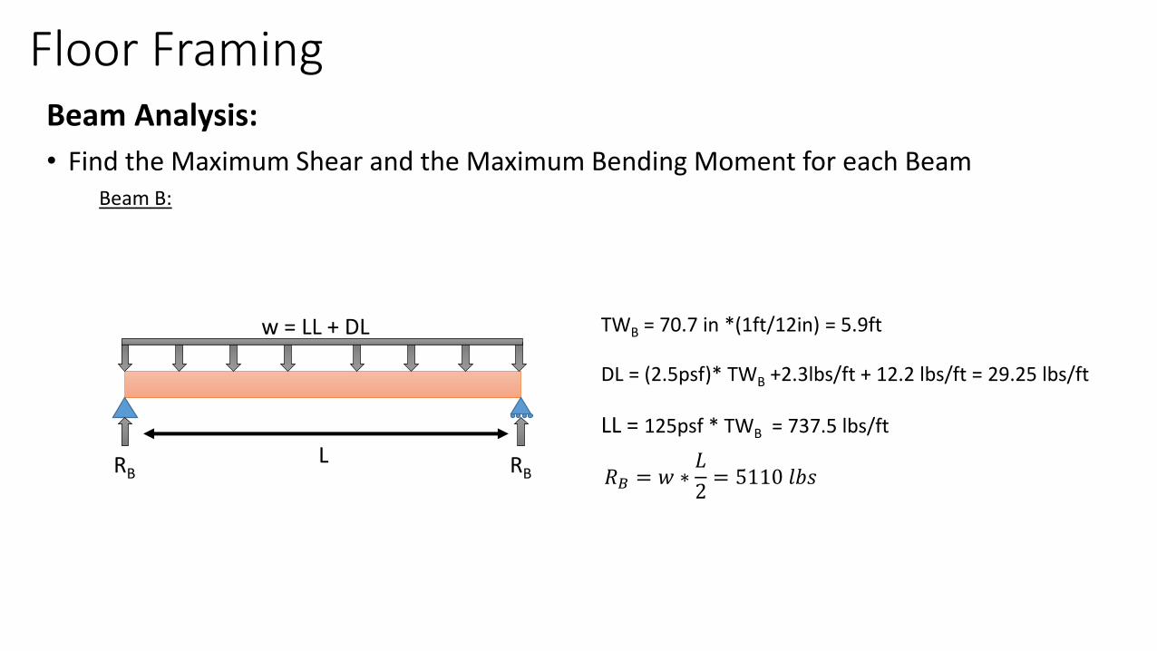
Floor FramingBeam Analysis:
• Find the Maximum Shear and the Maximum Bending Moment for each BeamBeam B:
w = LL + DL
RB RBL
TWB = 70.7 in *(1ft/12in) = 5.9ft
DL = (2.5psf)* TWB +2.3lbs/ft + 12.2 lbs/ft = 29.25 lbs/ft
LL = 125psf * TWB = 737.5 lbs/ft
𝑅𝐵 = 𝑤 ∗𝐿
2= 5110 𝑙𝑏𝑠

Floor FramingBeam Analysis:
• Find the Maximum Shear and the Maximum Bending Moment for each BeamBeam B:
Shear, V
RB
L/2 L/2
Mmax
Moment, M
x x
𝑉𝑚𝑎𝑥 = 𝑅𝐵 = 𝑤 ∗𝐿
2𝑀𝑚𝑎𝑥 =
1
2∗ (𝑅𝐵 ∗
𝐿
2) = 𝑤 ∗
𝐿2
8
𝑉𝑚𝑎𝑥 = 5110 𝑙𝑏𝑠 𝑀𝑚𝑎𝑥 = 17029 𝑓𝑡 − 𝑙𝑏 = 204349𝑖𝑛 − 𝑙𝑏
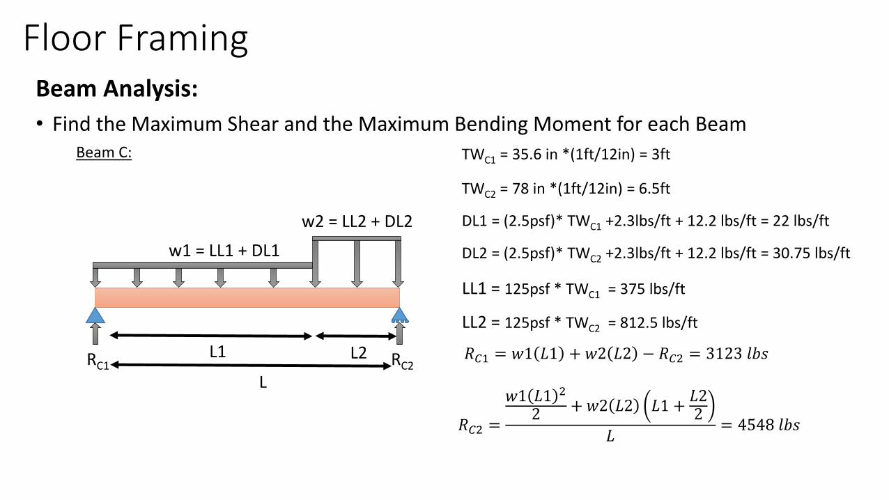
Floor FramingBeam Analysis:
• Find the Maximum Shear and the Maximum Bending Moment for each BeamBeam C:
w1 = LL1 + DL1
RC1 RC2L1 L2
L
TWC2 = 78 in *(1ft/12in) = 6.5ft
DL1 = (2.5psf)* TWC1 +2.3lbs/ft + 12.2 lbs/ft = 22 lbs/ft
LL2 = 125psf * TWC2 = 812.5 lbs/ft
𝑅𝐶2 =
𝑤1 𝐿1 2
2 + 𝑤2 𝐿2 𝐿1 +𝐿22
𝐿= 4548 𝑙𝑏𝑠
w2 = LL2 + DL2
TWC1 = 35.6 in *(1ft/12in) = 3ft
DL2 = (2.5psf)* TWC2 +2.3lbs/ft + 12.2 lbs/ft = 30.75 lbs/ft
LL1 = 125psf * TWC1 = 375 lbs/ft
𝑅𝐶1 = 𝑤1 𝐿1 + 𝑤2 𝐿2 − 𝑅𝐶2 = 3123 𝑙𝑏𝑠
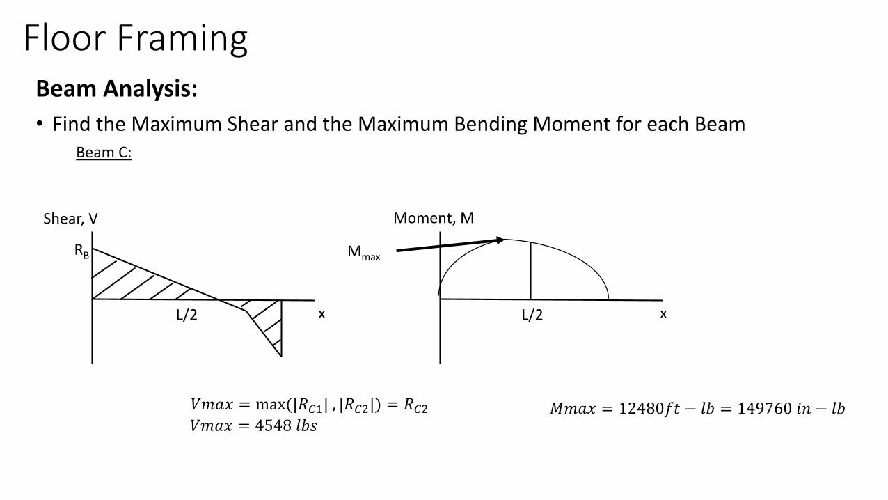
Floor FramingBeam Analysis:
• Find the Maximum Shear and the Maximum Bending Moment for each BeamBeam C:
Shear, V
RB
L/2 L/2
Mmax
Moment, M
x x
𝑉𝑚𝑎𝑥 = max(|𝑅𝐶1| , |𝑅𝐶2|) = 𝑅𝐶2𝑉𝑚𝑎𝑥 = 4548 𝑙𝑏𝑠
𝑀𝑚𝑎𝑥 = 12480𝑓𝑡 − 𝑙𝑏 = 149760 𝑖𝑛 − 𝑙𝑏

Floor FramingBeam Analysis:
• Find the Maximum Shear and the Maximum Bending Moment for each BeamBeam D:
w = LL + DL
RD RDL
TWD = 42.4 in *(1ft/12in) = 3.5ft
DL = (2.5psf)* TWD +2.3lbs/ft + 6.1 lbs/ft = 17.15 lbs/ft
LL = 125psf * TWD = 437.5 lbs/ft
𝑅𝐷 = 𝑤 ∗𝐿
2= 1212 𝑙𝑏𝑠
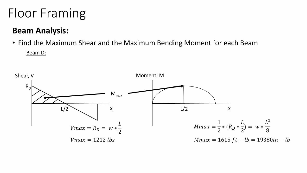
Floor FramingBeam Analysis:
• Find the Maximum Shear and the Maximum Bending Moment for each BeamBeam D:
Shear, V
RD
L/2 L/2
Mmax
Moment, M
x x
𝑉𝑚𝑎𝑥 = 𝑅𝐷 = 𝑤 ∗𝐿
2𝑀𝑚𝑎𝑥 =
1
2∗ (𝑅𝐷 ∗
𝐿
2) = 𝑤 ∗
𝐿2
8
𝑉𝑚𝑎𝑥 = 1212 𝑙𝑏𝑠 𝑀𝑚𝑎𝑥 = 1615 𝑓𝑡 − 𝑙𝑏 = 19380𝑖𝑛 − 𝑙𝑏
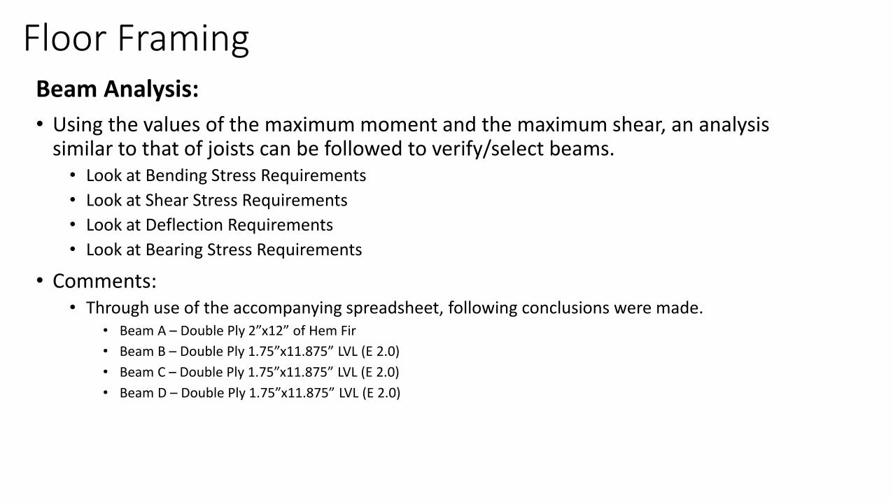
Floor FramingBeam Analysis:
• Using the values of the maximum moment and the maximum shear, an analysis similar to that of joists can be followed to verify/select beams.• Look at Bending Stress Requirements
• Look at Shear Stress Requirements
• Look at Deflection Requirements
• Look at Bearing Stress Requirements
• Comments:• Through use of the accompanying spreadsheet, following conclusions were made.
• Beam A – Double Ply 2”x12” of Hem Fir
• Beam B – Double Ply 1.75”x11.875” LVL (E 2.0)
• Beam C – Double Ply 1.75”x11.875” LVL (E 2.0)
• Beam D – Double Ply 1.75”x11.875” LVL (E 2.0)
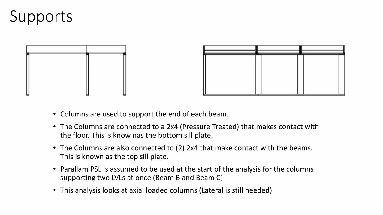
Supports
• Columns are used to support the end of each beam.
• The Columns are connected to a 2x4 (Pressure Treated) that makes contact with the floor. This is know nas the bottom sill plate.
• The Columns are also connected to (2) 2x4 that make contact with the beams. This is known as the top sill plate.
• Parallam PSL is assumed to be used at the start of the analysis for the columns supporting two LVLs at once (Beam B and Beam C)
• This analysis looks at axial loaded columns (Lateral is still needed)
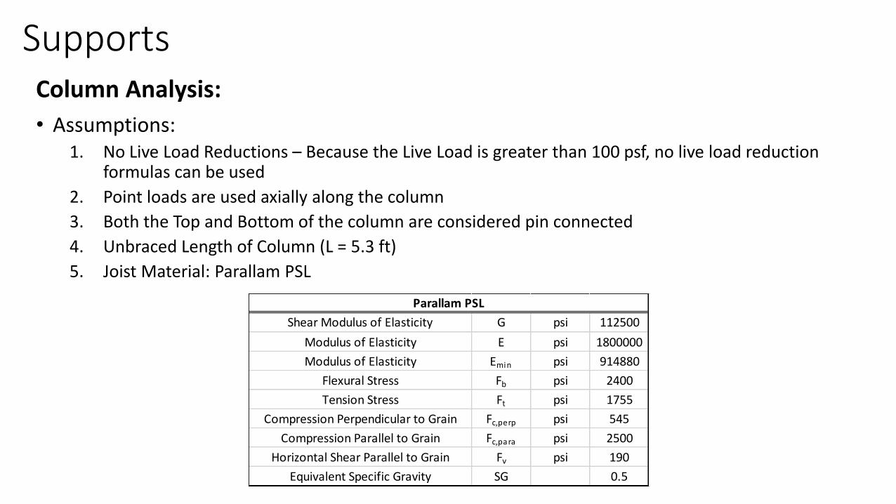
SupportsColumn Analysis:
• Assumptions: 1. No Live Load Reductions – Because the Live Load is greater than 100 psf, no live load reduction
formulas can be used
2. Point loads are used axially along the column
3. Both the Top and Bottom of the column are considered pin connected
4. Unbraced Length of Column (L = 5.3 ft)
5. Joist Material: Parallam PSL
Shear Modulus of Elasticity G psi 112500
Modulus of Elasticity E psi 1800000
Modulus of Elasticity Emin psi 914880
Flexural Stress Fb psi 2400
Tension Stress Ft psi 1755
Compression Perpendicular to Grain Fc,perp psi 545
Compression Parallel to Grain Fc,para psi 2500
Horizontal Shear Parallel to Grain Fv psi 190
Equivalent Specific Gravity SG 0.5
Parallam PSL
SupportsColumn Analysis:
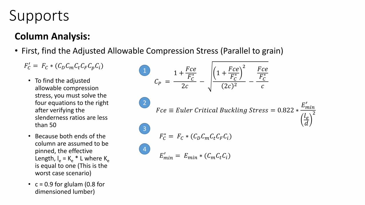
• First, find the Adjusted Allowable Compression Stress (Parallel to grain)
𝐹𝐶′ = 𝐹𝐶 ∗ (𝐶𝐷𝐶𝑚𝐶𝑡𝐶𝐹𝐶𝑝𝐶𝑖)
𝐶𝑃 =1 +
𝐹𝑐𝑒𝐹𝐶∗
2𝑐−
1 +𝐹𝑐𝑒𝐹𝐶∗
2
2𝑐 2 −
𝐹𝑐𝑒𝐹𝐶∗
𝑐
𝐹𝑐𝑒 ≡ 𝐸𝑢𝑙𝑒𝑟 𝐶𝑟𝑖𝑡𝑖𝑐𝑎𝑙 𝐵𝑢𝑐𝑘𝑙𝑖𝑛𝑔 𝑆𝑡𝑟𝑒𝑠𝑠 = 0.822 ∗𝐸𝑚𝑖𝑛′
𝑙𝑒𝑑
2
𝐹𝐶∗ = 𝐹𝐶 ∗ (𝐶𝐷𝐶𝑚𝐶𝑡𝐶𝐹𝐶𝑖)
𝐸𝑚𝑖𝑛′ = 𝐸𝑚𝑖𝑛 ∗ (𝐶𝑚𝐶𝑡𝐶𝑖)
1
2
3
4
• To find the adjusted allowable compression stress, you must solve the four equations to the right after verifying the slenderness ratios are less than 50
• Because both ends of the column are assumed to be pinned, the effective Length, le = Ke * L where Keis equal to one (This is the worst case scenario)
• c = 0.9 for glulam (0.8 for dimensioned lumber)
SupportsColumn Analysis:
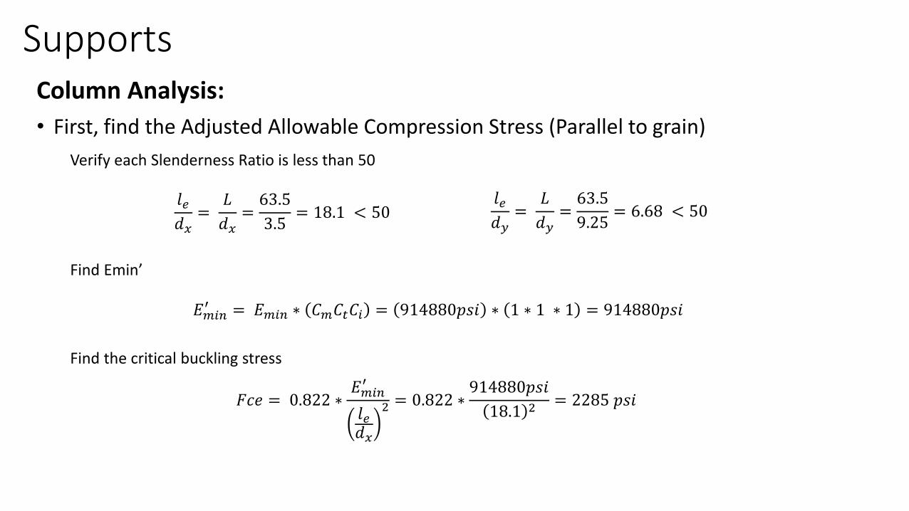
• First, find the Adjusted Allowable Compression Stress (Parallel to grain)
Verify each Slenderness Ratio is less than 50
𝑙𝑒𝑑𝑥
=𝐿
𝑑𝑥=63.5
3.5= 18.1 < 50
𝑙𝑒𝑑𝑦
=𝐿
𝑑𝑦=63.5
9.25= 6.68 < 50
Find Emin’
𝐸𝑚𝑖𝑛′ = 𝐸𝑚𝑖𝑛 ∗ 𝐶𝑚𝐶𝑡𝐶𝑖 = 914880𝑝𝑠𝑖 ∗ 1 ∗ 1 ∗ 1 = 914880𝑝𝑠𝑖
Find the critical buckling stress
𝐹𝑐𝑒 = 0.822 ∗𝐸𝑚𝑖𝑛′
𝑙𝑒𝑑𝑥
2 = 0.822 ∗914880𝑝𝑠𝑖
18.1 2 = 2285 𝑝𝑠𝑖
SupportsColumn Analysis:
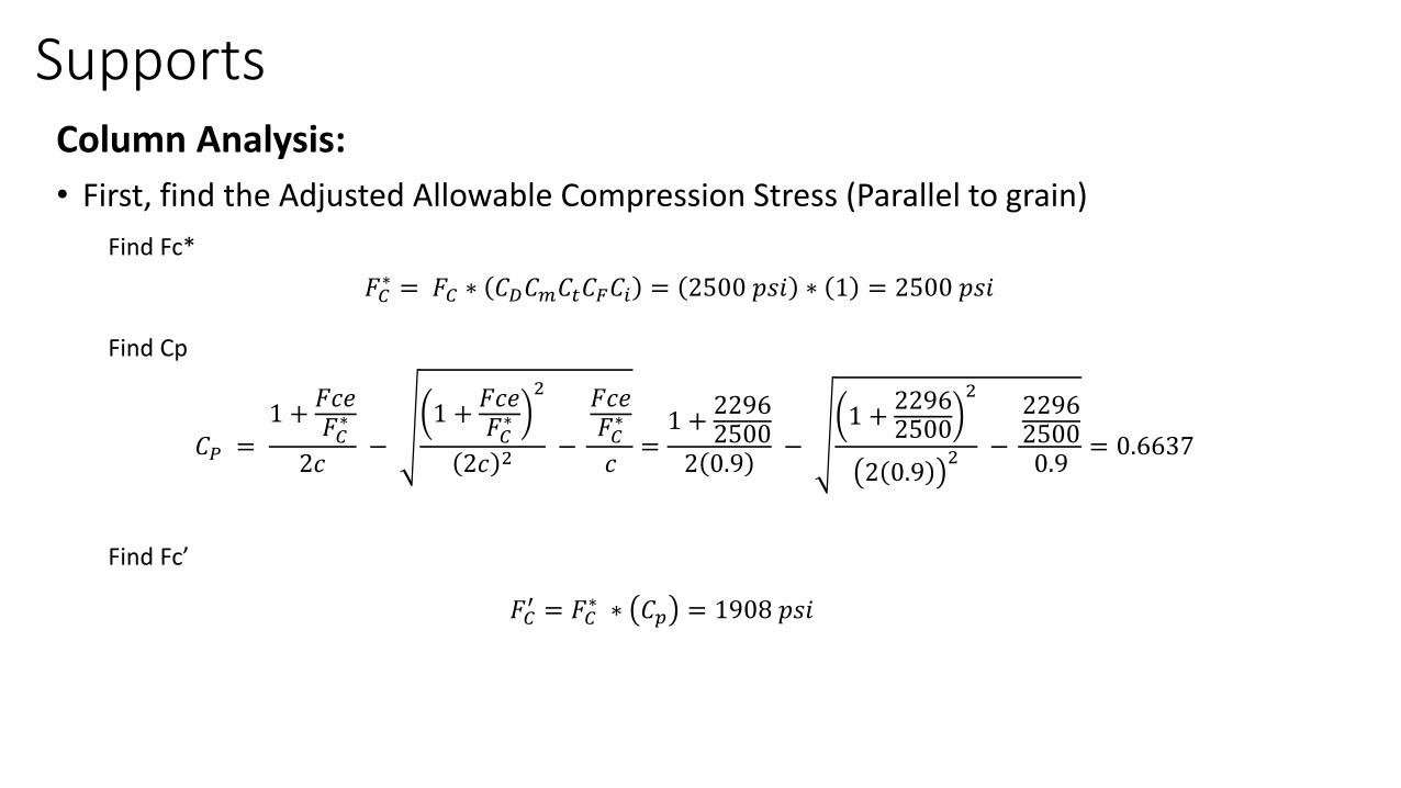
• First, find the Adjusted Allowable Compression Stress (Parallel to grain)
Find Fc*
Find Cp
Find Fc’
𝐹𝐶∗ = 𝐹𝐶 ∗ 𝐶𝐷𝐶𝑚𝐶𝑡𝐶𝐹𝐶𝑖 = 2500 𝑝𝑠𝑖 ∗ 1 = 2500 𝑝𝑠𝑖
𝐶𝑃 =1 +
𝐹𝑐𝑒𝐹𝐶∗
2𝑐−
1 +𝐹𝑐𝑒𝐹𝐶∗
2
2𝑐 2 −
𝐹𝑐𝑒𝐹𝐶∗
𝑐=1 +
22962500
2 0.9−
1 +22962500
2
2 0.92 −
229625000.9
= 0.6637
𝐹𝐶′ = 𝐹𝐶
∗ ∗ 𝐶𝑝 = 1908 𝑝𝑠𝑖
SupportsColumn Analysis:
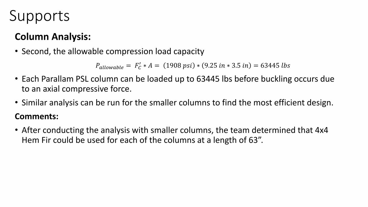
• Second, the allowable compression load capacity
• Each Parallam PSL column can be loaded up to 63445 lbs before buckling occurs due to an axial compressive force.
• Similar analysis can be run for the smaller columns to find the most efficient design.
Comments:
• After conducting the analysis with smaller columns, the team determined that 4x4 Hem Fir could be used for each of the columns at a length of 63”.
𝑃𝑎𝑙𝑙𝑜𝑤𝑎𝑏𝑙𝑒 = 𝐹𝐶′ ∗ 𝐴 = 1908 𝑝𝑠𝑖 ∗ 9.25 𝑖𝑛 ∗ 3.5 𝑖𝑛 = 63445 𝑙𝑏𝑠
Lateral Loading Analysis
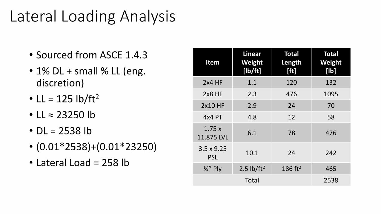
• Sourced from ASCE 1.4.3
• 1% DL + small % LL (eng.discretion)
• LL = 125 lb/ft2
• LL ≈ 23250 lb
• DL = 2538 lb
• (0.01*2538)+(0.01*23250)
• Lateral Load = 258 lb
Item LinearWeight [lb/ft]
TotalLength
[ft]
Total Weight
[lb]
2x4 HF 1.1 120 132
2x8 HF 2.3 476 1095
2x10 HF 2.9 24 70
4x4 PT 4.8 12 58
1.75 x 11.875 LVL
6.1 78 476
3.5 x 9.25 PSL
10.1 24 242
¾” Ply 2.5 lb/ft2 186 ft2 465
Total 2538
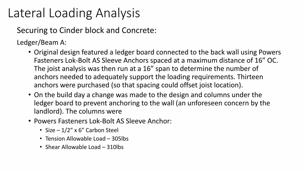
Lateral Loading AnalysisSecuring to Cinder block and Concrete:
Ledger/Beam A:
• Original design featured a ledger board connected to the back wall using Powers Fasteners Lok-Bolt AS Sleeve Anchors spaced at a maximum distance of 16” OC. The joist analysis was then run at a 16” span to determine the number of anchors needed to adequately support the loading requirements. Thirteen anchors were purchased (so that spacing could offset joist location).
• On the build day a change was made to the design and columns under the ledger board to prevent anchoring to the wall (an unforeseen concern by the landlord). The columns were
• Powers Fasteners Lok-Bolt AS Sleeve Anchor:• Size – 1/2” x 6” Carbon Steel
• Tension Allowable Load – 305lbs
• Shear Allowable Load – 310lbs
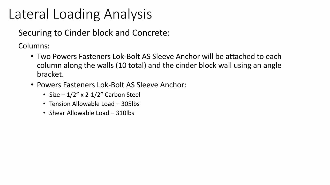
Lateral Loading AnalysisSecuring to Cinder block and Concrete:
Columns:
• Two Powers Fasteners Lok-Bolt AS Sleeve Anchor will be attached to each column along the walls (10 total) and the cinder block wall using an angle bracket.
• Powers Fasteners Lok-Bolt AS Sleeve Anchor:• Size – 1/2” x 2-1/2” Carbon Steel
• Tension Allowable Load – 305lbs
• Shear Allowable Load – 310lbs
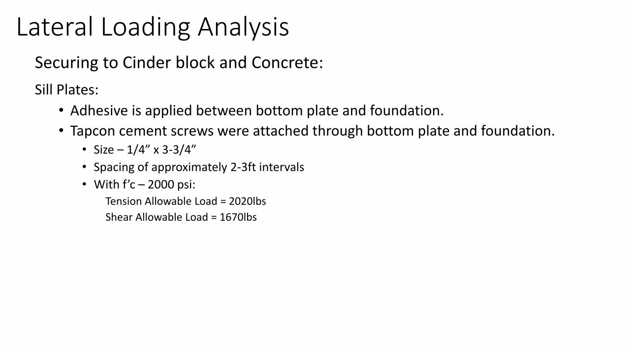
Lateral Loading AnalysisSecuring to Cinder block and Concrete:
Sill Plates:
• Adhesive is applied between bottom plate and foundation.
• Tapcon cement screws were attached through bottom plate and foundation.• Size – 1/4” x 3-3/4”
• Spacing of approximately 2-3ft intervals
• With f’c – 2000 psi: Tension Allowable Load = 2020lbs
Shear Allowable Load = 1670lbs
Handrail/Guardrail Analysis[4]
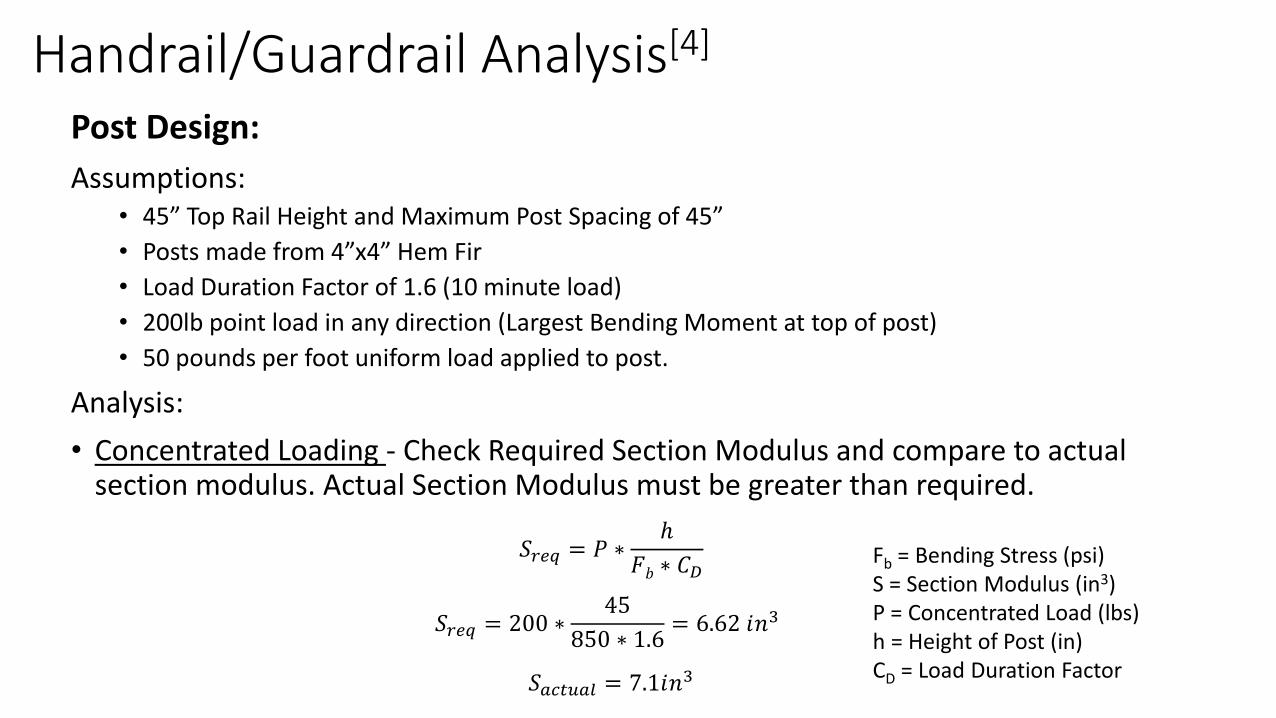
Post Design:
Assumptions:• 45” Top Rail Height and Maximum Post Spacing of 45”
• Posts made from 4”x4” Hem Fir
• Load Duration Factor of 1.6 (10 minute load)
• 200lb point load in any direction (Largest Bending Moment at top of post)
• 50 pounds per foot uniform load applied to post.
Analysis:
• Concentrated Loading - Check Required Section Modulus and compare to actual section modulus. Actual Section Modulus must be greater than required.
𝑆𝑟𝑒𝑞 = 𝑃 ∗ℎ
𝐹𝑏 ∗ 𝐶𝐷Fb = Bending Stress (psi)S = Section Modulus (in3)P = Concentrated Load (lbs)h = Height of Post (in)CD = Load Duration Factor
𝑆𝑟𝑒𝑞 = 200 ∗45
850 ∗ 1.6= 6.62 𝑖𝑛3
𝑆𝑎𝑐𝑡𝑢𝑎𝑙 = 7.1𝑖𝑛3
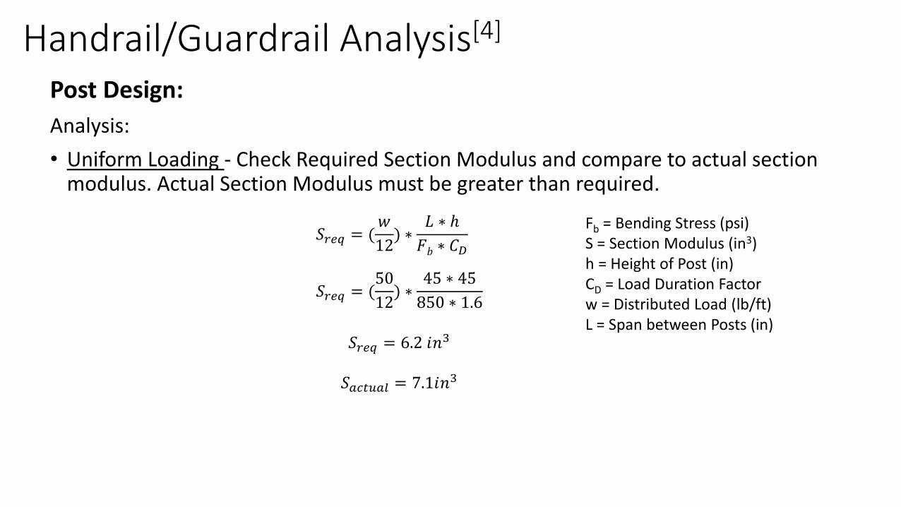
Handrail/Guardrail Analysis[4]
Post Design:
Analysis:
• Uniform Loading - Check Required Section Modulus and compare to actual section modulus. Actual Section Modulus must be greater than required.
𝑆𝑟𝑒𝑞 = (𝑤
12) ∗
𝐿 ∗ ℎ
𝐹𝑏 ∗ 𝐶𝐷
Fb = Bending Stress (psi)S = Section Modulus (in3)h = Height of Post (in)CD = Load Duration Factorw = Distributed Load (lb/ft)L = Span between Posts (in)
𝑆𝑟𝑒𝑞 = (50
12) ∗
45 ∗ 45
850 ∗ 1.6
𝑆𝑟𝑒𝑞 = 6.2 𝑖𝑛3
𝑆𝑎𝑐𝑡𝑢𝑎𝑙 = 7.1𝑖𝑛3
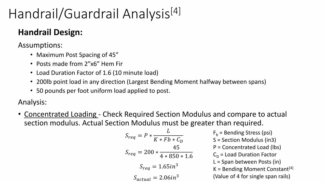
Handrail/Guardrail Analysis[4]
Handrail Design:
Assumptions:• Maximum Post Spacing of 45”
• Posts made from 2”x6” Hem Fir
• Load Duration Factor of 1.6 (10 minute load)
• 200lb point load in any direction (Largest Bending Moment halfway between spans)
• 50 pounds per foot uniform load applied to post.
Analysis:
• Concentrated Loading - Check Required Section Modulus and compare to actual section modulus. Actual Section Modulus must be greater than required.
𝑆𝑟𝑒𝑞 = 𝑃 ∗𝐿
𝐾 ∗ 𝐹𝑏 ∗ 𝐶𝐷
Fb = Bending Stress (psi)S = Section Modulus (in3)P = Concentrated Load (lbs)CD = Load Duration FactorL = Span between Posts (in)K = Bending Moment Constant[4]
(Value of 4 for single span rails)
𝑆𝑟𝑒𝑞 = 200 ∗45
4 ∗ 850 ∗ 1.6
𝑆𝑟𝑒𝑞 = 1.65𝑖𝑛3
𝑆𝑎𝑐𝑡𝑢𝑎𝑙 = 2.06𝑖𝑛3
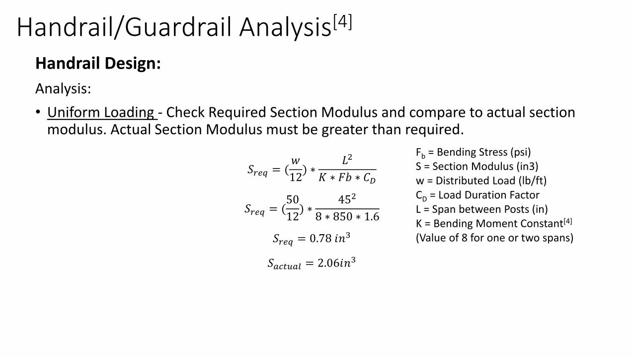
Handrail/Guardrail Analysis[4]
Handrail Design:
Analysis:
• Uniform Loading - Check Required Section Modulus and compare to actual section modulus. Actual Section Modulus must be greater than required.
𝑆𝑟𝑒𝑞 = (𝑤
12) ∗
𝐿2
𝐾 ∗ 𝐹𝑏 ∗ 𝐶𝐷
Fb = Bending Stress (psi)S = Section Modulus (in3)w = Distributed Load (lb/ft)CD = Load Duration FactorL = Span between Posts (in)K = Bending Moment Constant[4]
(Value of 8 for one or two spans)
𝑆𝑟𝑒𝑞 = (50
12) ∗
452
8 ∗ 850 ∗ 1.6
𝑆𝑟𝑒𝑞 = 0.78 𝑖𝑛3
𝑆𝑎𝑐𝑡𝑢𝑎𝑙 = 2.06𝑖𝑛3
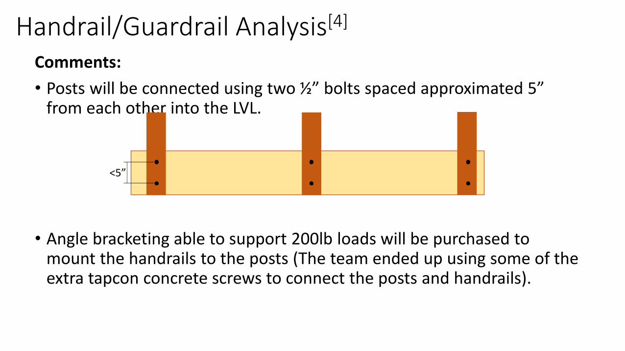
Handrail/Guardrail Analysis[4]
Comments:
• Posts will be connected using two ½” bolts spaced approximated 5” from each other into the LVL.
• Angle bracketing able to support 200lb loads will be purchased to mount the handrails to the posts (The team ended up using some of the extra tapcon concrete screws to connect the posts and handrails).
<5”
References1. Aghayere, Abi O., and Jason Vigil. Structural Wood Design. Boca Raton, FL: CRC, 2017.
Print.
2. Http://www.woodbywy.com/author/kschultz/. "Microllam LVL Beams." Weyerhaeuser. N.p., 2016. Web. 07 Dec. 2016.
3. Stalnaker, Judith J., and Ernest C. Harris. Structural Design in Wood. New York: Chapman & Hall, 1997. Print.
4. McCaffrey, Brian. "Design of Commercial/Industrial Guardrail Systems for Fall Protection .“, 2013. Web. 8 May 2017. <https://www.cedengineering.com/userfiles/Design%20of%20Com-Ind%20%20Guardrail%20Sys%20for%20Fall%20Protection%E2%80%A6.pdf>.
5. ASCE Standards 7-10
6. Simpson Strong Tie Catalogue
7. NDS literature
8. Tapcon product literature
9. Powers Fasteners product literature


![CE 160 Notes - Live Load Lab 5 notes.pdfVukazich CE 160 Live Load Notes [L5] 3 Floor Live Load reduction is permitted in most cases for members with large influence area (A I) Tributary](https://static.fdocuments.net/doc/165x107/5f0db8747e708231d43bc088/ce-160-notes-live-load-lab-5-notespdf-vukazich-ce-160-live-load-notes-l5-3.jpg)


