Metrode: Cladding Applications - Nickel Alloys CD 2011/Technical Literature/Strip...welding...
24
Rev 01 January 2011 1 __________________________________________________________________________ 1 ELECTROSLAG STRIP CLADDING (ESW) Metrode: Cladding Applications
Transcript of Metrode: Cladding Applications - Nickel Alloys CD 2011/Technical Literature/Strip...welding...

Rev 01 January 2011
1 __________________________________________________________________________
1111
ELECTROSLAG STRIP CLADDING (ESW)
Metrode: Cladding Applications

Rev 01 January 2011
2 __________________________________________________________________________
Table of Contents
Introduction .................................................................................... 2
Cladding Processes ....................................................................... 2
Strip Cladding Process .................................................................. 3
Material Availability ........................................................................ 4
Dilution ........................................................................................... 7
Alloying Vectors .............................................................................. 7
Parameter Effects .......................................................................... 8
Current ........................................................................................... 8
Voltage ........................................................................................... 9
Travel Speed ............................................................................... 10
Strip Thickness (Constant heat input) ......................................... 11
Strip Width (308L, Constant Current Density) ............................. 12
Heat Input .................................................................................... 13
Strip .............................................................................................. 14
Strip Positioning (Circumferential Cladding) ................................ 14
Residual Stresses ........................................................................ 15
Lane Closure ............................................................................... 16
Magnetic Steering. ....................................................................... 17
Increased Stick Out Effects ......................................................... 18
IntroductionIntroductionIntroductionIntroduction
Cladding is a fundamental process to the fabrication industry and is applied across the whole spectrum of applications; including Nuclear, Petrochemical and Oil and Gas. The ability to fabricate in C Mn, low alloy steels for the main structure, utilising the strength and other physical properties, then applying a corrosion resistant layer in the area where this is needed, provides unique flexibility and cost savings.
There are many ways to apply this corrosion resistant layer from, roll cladding at the steel rolling stage and explosive cladding of existing plate, however the most flexible is weld cladding. All the
welding processes can be utilised however due to constraints in the physical requirements, some are better suited than others.
Cladding ProcessesCladding ProcessesCladding ProcessesCladding Processes
In the main GTAW with cold or hot wire feed is used for smaller areas and in restricted access situations i.e. internal bore cladding. This can be automated, resulting in a reproducible deposit. For larger, thicker sections, the GTAW process lacks the deposition rate and therefore strip cladding processes are better suited.
gjenkins
Appendix - Data Sheets
Rev 01 January 2011
3 __________________________________________________________________________
Strip Cladding ProcessStrip Cladding ProcessStrip Cladding ProcessStrip Cladding Process
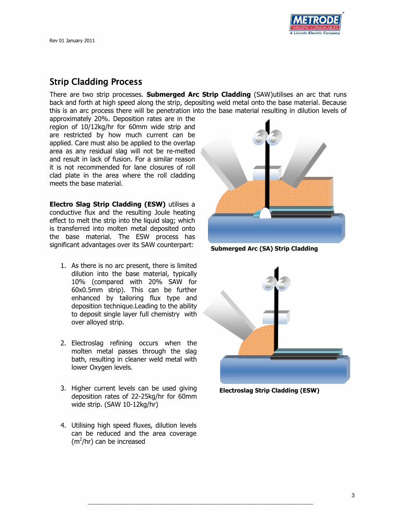
There are two strip processes. Submerged Arc Strip Cladding (SAW)utilises an arc that runs back and forth at high speed along the strip, depositing weld metal onto the base material. Because this is an arc process there will be penetration into the base material resulting in dilution levels of approximately 20%. Deposition rates are in the region of 10/12kg/hr for 60mm wide strip and are restricted by how much current can be applied. Care must also be applied to the overlap area as any residual slag will not be re-melted and result in lack of fusion. For a similar reason it is not recommended for lane closures of roll clad plate in the area where the roll cladding meets the base material.
Electro Slag Strip Cladding (ESW) utilises a
conductive flux and the resulting Joule heating effect to melt the strip into the liquid slag; which is transferred into molten metal deposited onto
the base material. The ESW process has significant advantages over its SAW counterpart:
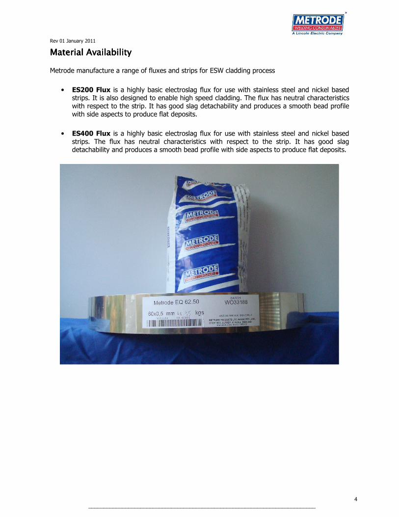
1. As there is no arc present, there is limited dilution into the base material, typically 10% (compared with 20% SAW for 60x0.5mm strip). This can be further enhanced by tailoring flux type and deposition technique.Leading to the ability to deposit single layer full chemistry with over alloyed strip.
2. Electroslag refining occurs when the
molten metal passes through the slag bath, resulting in cleaner weld metal with lower Oxygen levels.
3. Higher current levels can be used giving
deposition rates of 22-25kg/hr for 60mm wide strip. (SAW 10-12kg/hr)
4. Utilising high speed fluxes, dilution levels can be reduced and the area coverage (m2/hr) can be increased
Submerged Arc (SA) Strip Cladding
Electroslag Strip Cladding (ESW) Electroslag Strip Cladding (ESW)
Rev 01 January 2011
4 __________________________________________________________________________
Material AvailabilityMaterial AvailabilityMaterial AvailabilityMaterial Availability
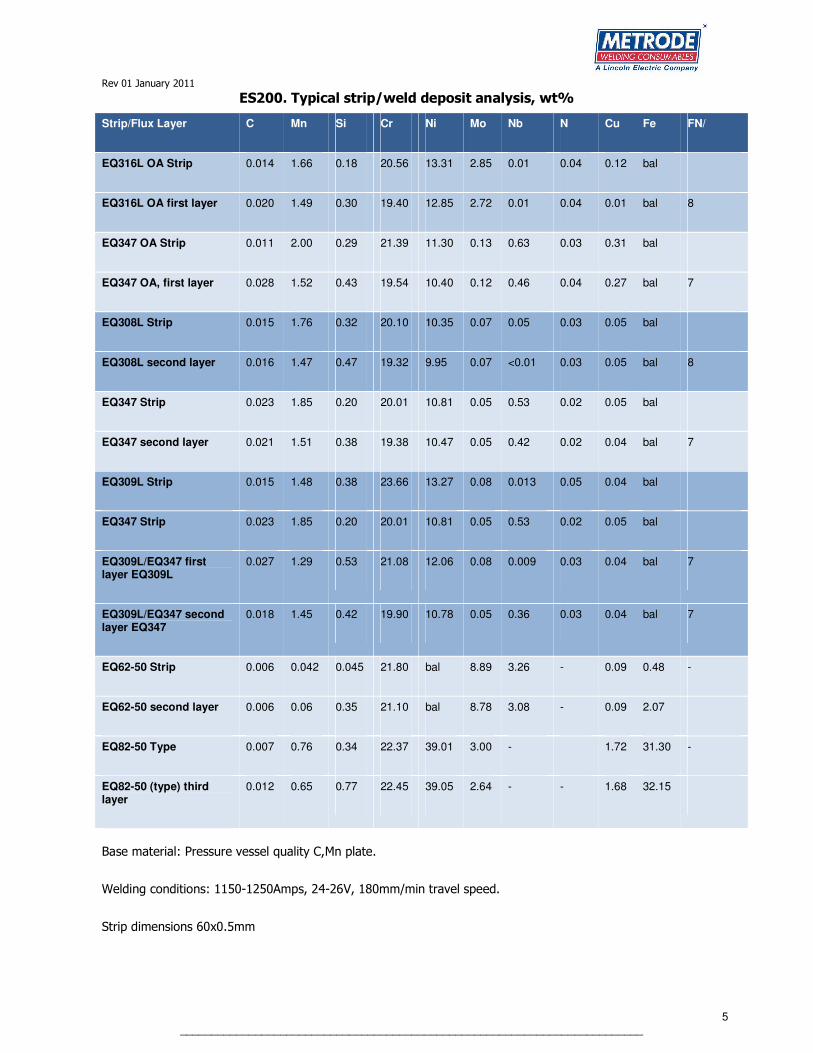
Metrode manufacture a range of fluxes and strips for ESW cladding process
• ES200 Flux is a highly basic electroslag flux for use with stainless steel and nickel based strips. It is also designed to enable high speed cladding. The flux has neutral characteristics with respect to the strip. It has good slag detachability and produces a smooth bead profile with side aspects to produce flat deposits.
• ES400 Flux is a highly basic electroslag flux for use with stainless steel and nickel based strips. The flux has neutral characteristics with respect to the strip. It has good slag detachability and produces a smooth bead profile with side aspects to produce flat deposits.
Rev 01 January 2011
5 __________________________________________________________________________
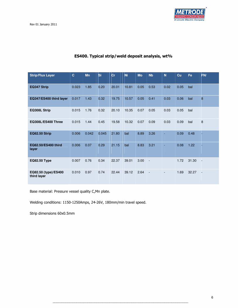
ES200. Typical strip/weld deposit analysis, wt%
Strip/Flux Layer C Mn Si Cr Ni Mo Nb N Cu Fe FN/
EQ316L OA Strip 0.014 1.66 0.18 20.56 13.31 2.85 0.01 0.04 0.12 bal
EQ316L OA first layer 0.020 1.49 0.30 19.40 12.85 2.72 0.01 0.04 0.01 bal 8
EQ347 OA Strip 0.011 2.00 0.29 21.39 11.30 0.13 0.63 0.03 0.31 bal
EQ347 OA, first layer 0.028 1.52 0.43 19.54 10.40 0.12 0.46 0.04 0.27 bal 7
EQ308L Strip 0.015 1.76 0.32 20.10 10.35 0.07 0.05 0.03 0.05 bal
EQ308L second layer 0.016 1.47 0.47 19.32 9.95 0.07 <0.01 0.03 0.05 bal 8
EQ347 Strip 0.023 1.85 0.20 20.01 10.81 0.05 0.53 0.02 0.05 bal
EQ347 second layer 0.021 1.51 0.38 19.38 10.47 0.05 0.42 0.02 0.04 bal 7
EQ309L Strip 0.015 1.48 0.38 23.66 13.27 0.08 0.013 0.05 0.04 bal
EQ347 Strip 0.023 1.85 0.20 20.01 10.81 0.05 0.53 0.02 0.05 bal
EQ309L/EQ347 first layer EQ309L
0.027 1.29 0.53 21.08 12.06 0.08 0.009 0.03 0.04 bal 7
EQ309L/EQ347 second layer EQ347
0.018 1.45 0.42 19.90 10.78 0.05 0.36 0.03 0.04 bal 7
EQ62-50 Strip 0.006 0.042 0.045 21.80 bal 8.89 3.26 - 0.09 0.48 -
EQ62-50 second layer 0.006 0.06 0.35 21.10 bal 8.78 3.08 - 0.09 2.07
EQ82-50 Type 0.007 0.76 0.34 22.37 39.01 3.00 - 1.72 31.30 -
EQ82-50 (type) third layer
0.012 0.65 0.77 22.45 39.05 2.64 - - 1.68 32.15
Base material: Pressure vessel quality C,Mn plate.
Welding conditions: 1150-1250Amps, 24-26V, 180mm/min travel speed.
Strip dimensions 60x0.5mm
Rev 01 January 2011
6 __________________________________________________________________________
ES400. Typical strip/weld deposit analysis, wt%
Strip/Flux Layer C Mn Si Cr Ni Mo Nb N Cu Fe FN/
EQ347 Strip 0.023 1.85 0.20 20.01 10.81 0.05 0.53 0.02 0.05 bal
EQ347/ES400 third layer 0.017 1.43 0.32 19.75 10.57 0.05 0.41 0.03 0.06 bal 8
EQ308L Strip 0.015 1.76 0.32 20.10 10.35 0.07 0.05 0.03 0.05 bal
EQ308L/ES400 Three 0.015 1.44 0.45 19.58 10.32 0.07 0.09 0.03 0.09 bal 8
EQ62.50 Strip 0.006 0.042 0.045 21.80 bal 8.89 3.26 - 0.09 0.48 -
EQ62.50/ES400 third layer
0.006 0.07 0.29 21.15 bal 8.83 3.21 - 0.08 1.22 -
EQ82.50 Type 0.007 0.76 0.34 22.37 39.01 3.00 - 1.72 31.30 -
EQ82.50 (type)/ES400 third layer
0.010 0.97 0.74 22.44 39.12 2.64 - - 1.69 32.27 -
Base material: Pressure vessel quality C,Mn plate.
Welding conditions: 1150-1250Amps, 24-26V, 180mm/min travel speed.
Strip dimensions 60x0.5mm
Rev 01 January 2011
7 __________________________________________________________________________
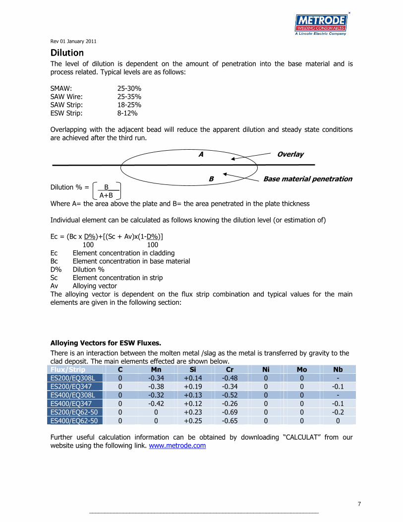
DilutionDilutionDilutionDilution The level of dilution is dependent on the amount of penetration into the base material and is process related. Typical levels are as follows:
SMAW: 25-30% SAW Wire: 25-35% SAW Strip: 18-25%
ESW Strip: 8-12% Overlapping with the adjacent bead will reduce the apparent dilution and steady state conditions
are achieved after the third run. A Overlay B Base material penetration Dilution % = B___ A+B
Where A= the area above the plate and B= the area penetrated in the plate thickness Individual element can be calculated as follows knowing the dilution level (or estimation of)
Ec = (Bc x D%)+[(Sc + Av)x(1-D%)]
100 100 Ec Element concentration in cladding Bc Element concentration in base material
D% Dilution % Sc Element concentration in strip Av Alloying vector
The alloying vector is dependent on the flux strip combination and typical values for the main elements are given in the following section:
Alloying Vectors for ESW Fluxes.
There is an interaction between the molten metal /slag as the metal is transferred by gravity to the clad deposit. The main elements effected are shown below. Flux/Strip C Mn Si Cr Ni Mo Nb
ES200/EQ308L 0 -0.34 +0.14 -0.48 0 0 -
ES200/EQ347 0 -0.38 +0.19 -0.34 0 0 -0.1
ES400/EQ308L 0 -0.32 +0.13 -0.52 0 0 -
ES400/EQ347 0 -0.42 +0.12 -0.26 0 0 -0.1
ES200/EQ62-50 0 0 +0.23 -0.69 0 0 -0.2
ES400/EQ62-50 0 0 +0.25 -0.65 0 0 0 Further useful calculation information can be obtained by downloading “CALCULAT” from our
website using the following link. www.metrode.com
Rev 01 January 2011
8 __________________________________________________________________________
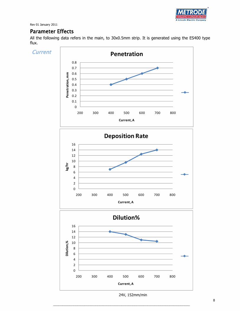
PPPParameter Effectsarameter Effectsarameter Effectsarameter Effects All the following data refers in the main, to 30x0.5mm strip. It is generated using the ES400 type flux.
CurrentCurrentCurrentCurrent
0
0.1
0.2
0.3
0.4
0.5
0.6
0.7
0.8
200 300 400 500 600 700 800
Pe
ne
tra
tio
n, m
m
Current, A
Penetration
0
2
4
6
8
10
12
14
16
200 300 400 500 600 700 800
kg
/h
r
Current, A
Deposition Rate
0
2
4
6
8
10
12
14
16
200 300 400 500 600 700 800
Dil
uti
on
,%
Current, A
Dilution%
24V, 152mm/min
Rev 01 January 2011
9 __________________________________________________________________________
0.4
0.45
0.5
0.55
0.6
0.65
0.7
23 24 25 26 27 28 29
Pe
ne
tra
tio
n, m
m
Voltage
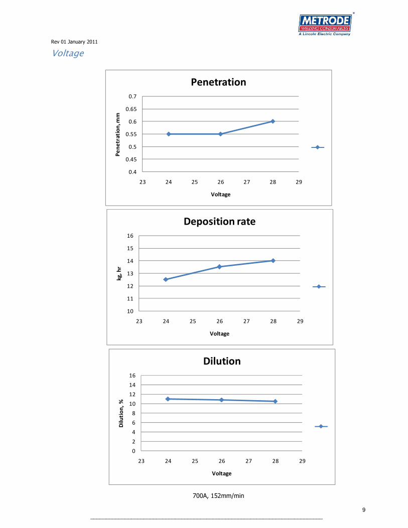
Penetration
Voltage
10
11
12
13
14
15
16
23 24 25 26 27 28 29
kg
, h
r
Voltage
Deposition rate
700A, 152mm/min
0
2
4
6
8
10
12
14
16
23 24 25 26 27 28 29
Dil
uti
on
, %
Voltage
Dilution

Rev 01 January 2011
10 __________________________________________________________________________
Travel Speed
0
0.1
0.2
0.3
0.4
0.5
0.6
0.7
0.8
130 150 170 190 210 230
Pe
ne
tra
tio
n, m
m
Travel Speed mm/min
Penetration
5
7
9
11
13
15
17
19
130 150 170 190 210 230
Dil
uti
on
, %
Travel Speed mm/min
Dilution
700A, 24V

Rev 01 January 2011
11 __________________________________________________________________________
Strip Thickness (Constant heat input, 40A/mm2, 24V, 152mm/min, travel speed)
0
0.1
0.2
0.3
0.4
0.5
0.6
0.7
0.8
0.9
1
0.2 0.3 0.4 0.5 0.6 0.7 0.8
Pe
ne
tra
tio
n, m
m
Strip Thickness, mm
Steel
308L
625
0
5
10
15
20
25
0.2 0.3 0.4 0.5 0.6 0.7 0.8
De
po
siti
on
ra
te,k
g/
hr
Strip Thickness, mm
Steel
308L
625
0
2
4
6
8
10
12
14
16
18
20
0.2 0.3 0.4 0.5 0.6 0.7 0.8
Dil
uti
on
, %
Strip Thickness, mm
Steel
308L
625

Rev 01 January 2011
12 __________________________________________________________________________
5
6
7
8
9
10
11
12
13
14
15
0 10 20 30 40 50 60 70
Dil
uti
on
, %
Strip Width ,mm
Dilution
Strip Width (308L, Constant Current Density, 40A/mm2 at 24V, 152mm/min, travel speed)
0
0.1
0.2
0.3
0.4
0.5
0.6
0.7
0 10 20 30 40 50 60 70
Pe
ne
tra
tio
n, m
m
Strip Width ,mm
Penetration
0
5
10
15
20
25
0 10 20 30 40 50 60 70
De
po
siti
on
Ra
te,
kg
/h
r
Strip Width ,mm
Deposition Rate

Rev 01 January 2011
13 __________________________________________________________________________
Heat InputHeat InputHeat InputHeat Input The classic heat input equation is given below:
Heat Input (kJ/mm) = AxVx60
Sx1000 Where A= Amps
V= Volts S=Travel speed mm/min
This gives the “point” heat input. When it is applied to strip cladding, the values are considerably higher than comparative wire processes due to the higher current levels that are used.
In strip processes the heat is delivered over the width of the strip and consequently the bead width influences the effective heat input. A point calculation is therefore misleading, and a term for the
bead width needs to be introduced to be more representative of how the heat input is distributed. The equation now becomes:-
Heat Input (kJ/mm2) = AxVx60
Sx1000xW
W= Bead width (mm) (Please note that the bead width is used in preference to the strip width, as the bead tends to spread either side of the initial strip dimension)
Examples and comparisons between the processes are given below:
Process Strip width-wire
ø, mm
Bead Width, mm
A V Travel speed
mm/min
kJ/mm kJ/mm2
SAW Wire 4.0 20 550 32 457 2.3 0.12
SAW Strip 60x0.5 65 750 26 140 8.35 0.13
ESW Strip 60x0.5 70 1250 25 180 10.41 0.15

Rev 01 January 2011
14 __________________________________________________________________________
StripStripStripStrip
Strip is commonly available in dimensions of 30, 60, 90 and 120mm widths x 0.5mm thick (the Japanese tend to use 50, 100, 150mm x 0.4mm thick). The choice of strip width is dependent on the base material thickness, vessel diameter and the amount of welding current that is available.
Strip width
mm
Minimum base
material
thickness, mm
Vessel ID minimum cladding,
mm
Vessel OD minimum cladding,
mm
Longitudinal Circumferential Longitudinal Circumferential
30 30 200 300 400 250
60 45 460 700 500 500
90 75 660 1070 1000 1300
120 100 960 1940 1500 2400
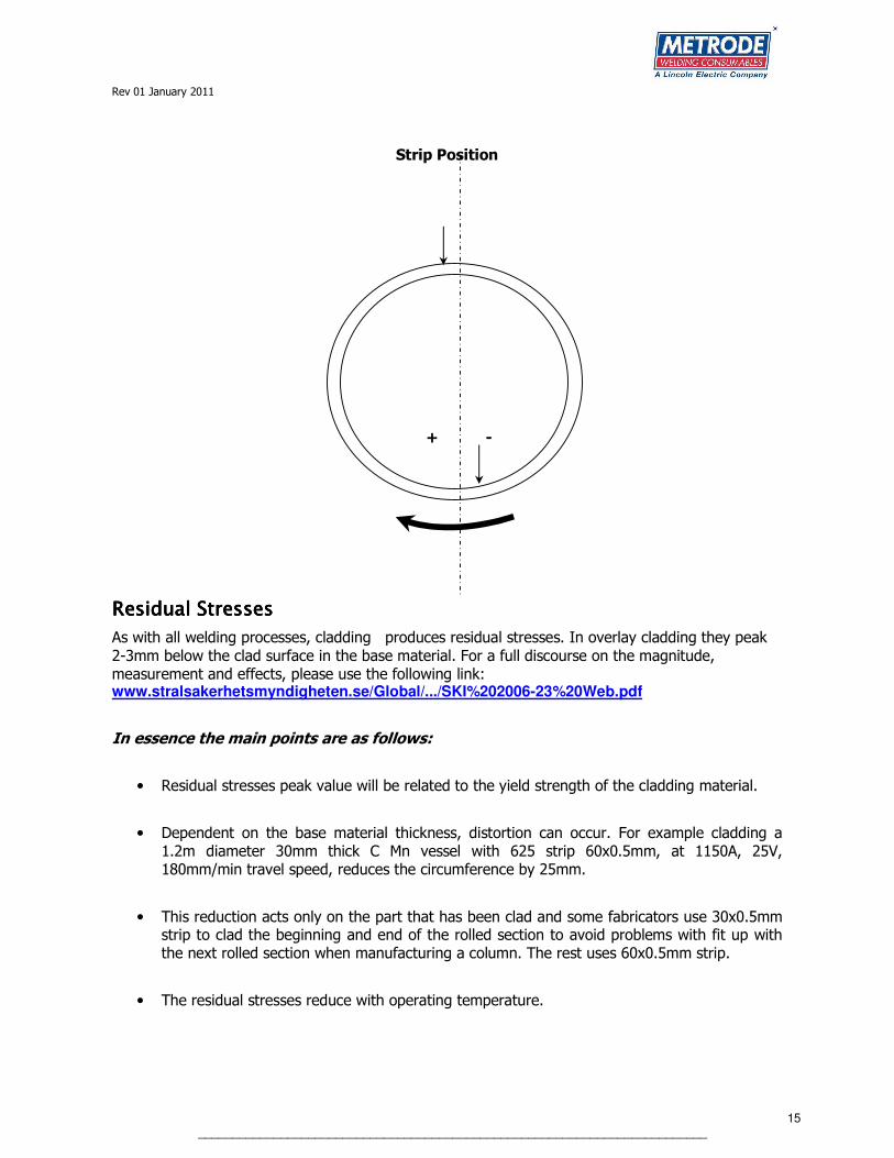
Strip Positioning (Circumferential CladdingStrip Positioning (Circumferential CladdingStrip Positioning (Circumferential CladdingStrip Positioning (Circumferential Cladding)))) When cladding a vessel it is essential to position the strip so that the weld pool is solidifying in the
bottom dead center (inside) or zenith (outside position). This then has an effect on the dilution level. Incorrect positioning can be seen to give substantialy higher levels of dilution than would be
expected. In addition with fully austenitic materials there is a danger of solidification cracking if the inclination is too positive, see diagram.
0
5
10
15
20
-6 -4 -2 0 2 4 6
Dil
uti
on
%
Inclination of Parent Material, °
1250A, 26V, 140mm/min travel speed.
Rev 01 January 2011
15 __________________________________________________________________________
Strip Position
+ -
Residual StressesResidual StressesResidual StressesResidual Stresses
As with all welding processes, cladding produces residual stresses. In overlay cladding they peak
2-3mm below the clad surface in the base material. For a full discourse on the magnitude, measurement and effects, please use the following link: www.stralsakerhetsmyndigheten.se/Global/.../SKI%202006-23%20Web.pdf
In essence the main points are as follows:
• Residual stresses peak value will be related to the yield strength of the cladding material.
• Dependent on the base material thickness, distortion can occur. For example cladding a 1.2m diameter 30mm thick C Mn vessel with 625 strip 60x0.5mm, at 1150A, 25V, 180mm/min travel speed, reduces the circumference by 25mm.
• This reduction acts only on the part that has been clad and some fabricators use 30x0.5mm strip to clad the beginning and end of the rolled section to avoid problems with fit up with the next rolled section when manufacturing a column. The rest uses 60x0.5mm strip.
• The residual stresses reduce with operating temperature.

Rev 01 January 2011
16 __________________________________________________________________________
Lane ClosureLane ClosureLane ClosureLane Closure
When roll clad material is used to fabricate a vessel, replacement corrosion resistant material has to be deposited over the area where the cladding has been cut back to allow the C Mn base
material to be welded. ESW strip cladding offers a “one hit” process to maximise production rates for both longitudinal and circumferential seams. A typical cladding preparation is shown below:
The cut back dimension, A, is dependent on the thickness of the base material.
Strip width will also be dependent on the cut back width and must be sufficient to allow enough material to close the lane.
Dilution levels will be affected by how much of the roll clad material is melted and included into the weld pool.
The choice of filler material will be dependent on the roll clad material and the design criteria of the
vessel. In general it is standard practice to use an over alloyed alloy with respect to the roll clad material.
SAW strip cladding is not suitable for this application as residual slag is trapped at the toes where the roll clad material meets the base material.
15°
A
Rev 01 January 2011
17 __________________________________________________________________________
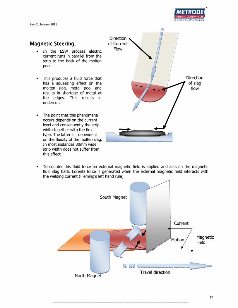
Magnetic Magnetic Magnetic Magnetic Steering.Steering.Steering.Steering.
• In the ESW process electric current runs in parallel from the strip to the back of the molten pool.
• This produces a fluid force that has a squeezing effect on the molten slag, metal pool and results in shortage of metal at the edges. This results in undercut.
• The point that this phenomena occurs depends on the current level and consequently the strip width together with the flux type. The latter is dependent on the fluidity of the molten slag. In most instances 30mm wide strip width does not suffer from this effect.
• To counter this fluid force an external magnetic field is applied and acts on the magnetic fluid slag bath. Lorentz force is generated when the external magnetic field interacts with the welding current (Fleming’s left hand rule)
Travel direction
Direction
of slag
flow
Direction
of Current
Flow
North Magnet
South Magnet
Motion
Current
Magnetic Field

Rev 01 January 2011
18 __________________________________________________________________________
Increased StickIncreased StickIncreased StickIncreased Stick----Out EffectsOut EffectsOut EffectsOut Effects
The standard stick-out length for both SAW and ESW strip cladding is 30mm. If this is increased, then there will be an increased pre-heating, I2R, effect on the strip. Stick-out lengths of 60/100mm can be used instead of the standard 30mm. By pre-heating the strip electrically, the amount of energy used to melt the strip in the slag pool or across the arc, is reduced. The effect of heating the strip results in increased deposition rate and reduced dilution.
It should be noted that a cladding head that crimps the strip before entering the slag pool (ESW) or across the arc (SAW) is required. The crimping increases the columnar strength of the strip which aids both starting the process and during use. Without it, the heating effect softens the strip
resulting in instability of the process.
Rev 00 11/10 DS: B-85 (pg 1 of 2)
DATA SHEET B-85
METRODE PRODUCTS LTD
HANWORTH LANE, CHERTSEY
SURREY, KT16 9LL
Tel: +44(0)1932 566721
Fax: +44(0)1932 565168 Sales
STAINLESS STEEL STRIP Fax: +44(0)1932 569449 Technical
Fax: +44(0)1932 566199 Export Email: [email protected]
Internet: http//www.metrode.com
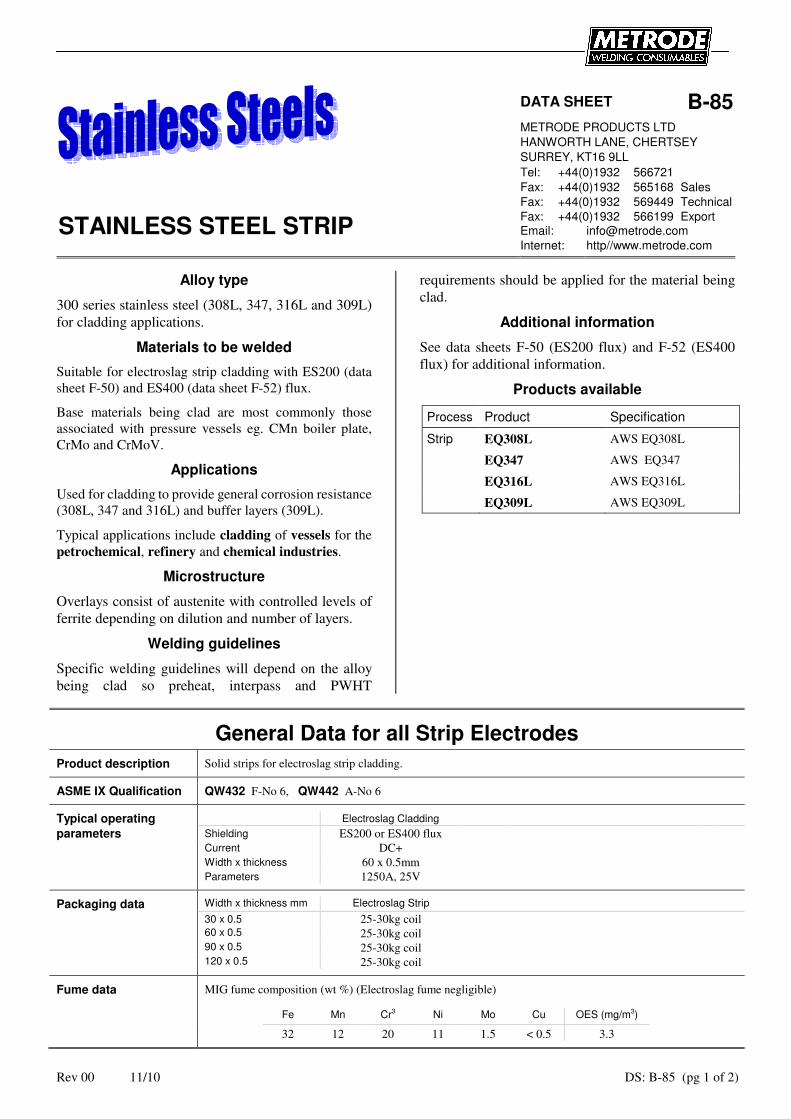
Alloy type
300 series stainless steel (308L, 347, 316L and 309L)
for cladding applications.
Materials to be welded
Suitable for electroslag strip cladding with ES200 (data
sheet F-50) and ES400 (data sheet F-52) flux.
Base materials being clad are most commonly those
associated with pressure vessels eg. CMn boiler plate,
CrMo and CrMoV.
Applications
Used for cladding to provide general corrosion resistance
(308L, 347 and 316L) and buffer layers (309L).
Typical applications include cladding of vessels for the
petrochemical, refinery and chemical industries.
Microstructure
Overlays consist of austenite with controlled levels of
ferrite depending on dilution and number of layers.
Welding guidelines
Specific welding guidelines will depend on the alloy
being clad so preheat, interpass and PWHT
requirements should be applied for the material being
clad.
Additional information
See data sheets F-50 (ES200 flux) and F-52 (ES400
flux) for additional information.
Products available
Process Product Specification
Strip EQ308L AWS EQ308L
EQ347 AWS EQ347
EQ316L AWS EQ316L
EQ309L AWS EQ309L
General Data for all Strip Electrodes
Product description Solid strips for electroslag strip cladding.
ASME IX Qualification QW432 F-No 6, QW442 A-No 6
Typical operating Electroslag Cladding
parameters Shielding ES200 or ES400 flux
Current DC+
Width x thickness 60 x 0.5mm
Parameters 1250A, 25V
Packaging data Width x thickness mm Electroslag Strip
30 x 0.5 25-30kg coil
60 x 0.5 25-30kg coil
90 x 0.5 25-30kg coil
120 x 0.5 25-30kg coil
Fume data MIG fume composition (wt %) (Electroslag fume negligible)
Fe Mn Cr3 Ni Mo Cu OES (mg/m3)
32 12 20 11 1.5 < 0.5 3.3

Rev 00 11/10 DS: B-85 (pg 2 of 2)
EQ308L Solid strip for electroslag cladding
Specifications AWS A5.9 EQ308L
BS EN ISO 14343-A B 19 9 L
BS EN ISO 14343-B BS 308L
Composition C Mn Si S P Cr Ni Mo Cu
(strip wt %) min -- 1.00 0.30 -- -- 19.50 9.00 -- --
max 0.030 2.50 0.65 0.020 0.030 21.00 11.00 0.50 0.50
typ 0.02 1.7 0.4 0.005 0.015 20.5 10.0 0.1 0.1
EQ347 Solid strip for electroslag cladding
Specifications AWS A5.9 EQ347
BS EN ISO 14343-A B 19 9 Nb
BS EN ISO 14343-B BS 347
Composition C Mn Si S P Cr Ni Mo Cu
(strip wt %) min -- 1.00 0.30 -- -- 19.00 9.00 -- --
max 0.080 2.50 0.65 0.020 0.030 21.00 11.00 0.50 0.50
typ 0.02 1.7 0.4 0.005 0.015 20.5 10.0 0.1 0.1
EQ316L Solid strip for electroslag cladding
Specifications AWS A5.9 EQ316L
BS EN ISO 14343-A B 19 12 3 L
BS EN ISO 14343-B BS 316L
Composition C Mn Si S P Cr Ni Mo Cu
(strip wt %) min -- 1.00 0.30 -- -- 18.00 11.00 2.50 --
max 0.030 2.50 0.65 0.020 0.030 20.00 14.00 3.00 0.50
typ 0.02 1.7 0.4 0.005 0.015 20.5 10.0 0.1 0.1
EQ309L Solid strip for electroslag cladding
Specifications AWS A5.9 EQ309L
BS EN ISO 14343-A B 23 12 L
BS EN ISO 14343-B BS 309L
Composition C Mn Si S P Cr Ni Mo Cu
(strip wt %) min -- 1.00 0.30 -- -- 23.00 12.00 -- --
max 0.030 2.50 0.65 0.020 0.030 25.00 14.00 0.50 0.50
typ 0.02 1.7 0.4 0.005 0.015 20.5 10.0 0.1 0.1
Rev 00 11/10 DS: D-85 (pg 1 of 2)
DATA SHEET D-85
METRODE PRODUCTS LTD
HANWORTH LANE, CHERTSEY
SURREY, KT16 9LL
Tel: +44(0)1932 566721
Fax: +44(0)1932 565168 Sales
625 STRIP Fax: +44(0)1932 569449 Technical
Fax: +44(0)1932 566199 Export Email: [email protected]
Internet: http//www.metrode.com
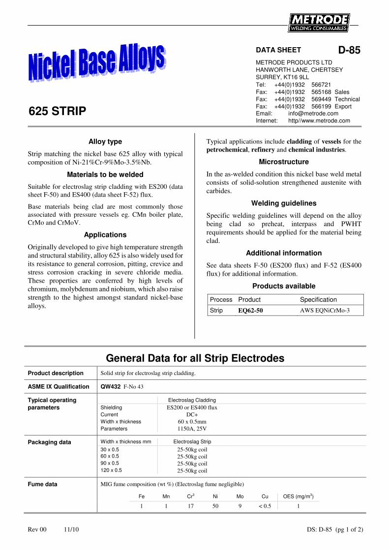
Alloy type
Strip matching the nickel base 625 alloy with typical
composition of Ni-21%Cr-9%Mo-3.5%Nb.
Materials to be welded
Suitable for electroslag strip cladding with ES200 (data
sheet F-50) and ES400 (data sheet F-52) flux.
Base materials being clad are most commonly those
associated with pressure vessels eg. CMn boiler plate,
CrMo and CrMoV.
Applications
Originally developed to give high temperature strength
and structural stability, alloy 625 is also widely used for
its resistance to general corrosion, pitting, crevice and
stress corrosion cracking in severe chloride media.
These properties are conferred by high levels of
chromium, molybdenum and niobium, which also raise
strength to the highest amongst standard nickel-base
alloys.
Typical applications include cladding of vessels for the
petrochemical, refinery and chemical industries.
Microstructure
In the as-welded condition this nickel base weld metal
consists of solid-solution strengthened austenite with
carbides.
Welding guidelines
Specific welding guidelines will depend on the alloy
being clad so preheat, interpass and PWHT
requirements should be applied for the material being
clad.
Additional information
See data sheets F-50 (ES200 flux) and F-52 (ES400
flux) for additional information.
Products available
Process Product Specification
Strip EQ62-50 AWS EQNiCrMo-3
General Data for all Strip Electrodes
Product description Solid strip for electroslag strip cladding.
ASME IX Qualification QW432 F-No 43
Typical operating Electroslag Cladding
parameters Shielding ES200 or ES400 flux
Current DC+
Width x thickness 60 x 0.5mm
Parameters 1150A, 25V
Packaging data Width x thickness mm Electroslag Strip
30 x 0.5 25-50kg coil
60 x 0.5 25-50kg coil
90 x 0.5 25-50kg coil
120 x 0.5 25-50kg coil
Fume data MIG fume composition (wt %) (Electroslag fume negligible)
Fe Mn Cr3 Ni Mo Cu OES (mg/m3)
1 1 17 50 9 < 0.5 1

Rev 00 11/10 DS: D-85 (pg 2 of 2)
EQ62-50 Solid strip for electroslag cladding
Specifications AWS A5.14 EQNiCrMo-3
BS EN ISO 18274 B Ni6625
Composition C Mn Si S P Cr Ni Mo Nb Fe Cu Al Ti
(strip wt %) min -- -- -- -- -- 20.0 58.0 8.0 3.15 -- -- -- --
max 0.10 0.50 0.50 0.015 0.020 23.0 Bal 10.0 4.15 1.0 0.5 0.4 0.4
typ 0.02 0.02 0.05 0.005 0.005 22 65 9 3.5 0.2 0.1 0.2 0.2
Rev 01 11/10 DS: F-50 (pg 1 of 1)
METRODE PRODUCTS LTD HANWORTH LANE, CHERTSEY SURREY, KT16 9LL Tel: +44(0)1932 566721
Fax: +44(0)1932 565168 Sales DATA SHEET F-50 +44(0)1932 569449 Technical
+44(0)1932 566199 Export
ES200 FLUX Email: [email protected] Internet: http//www.metrode.com
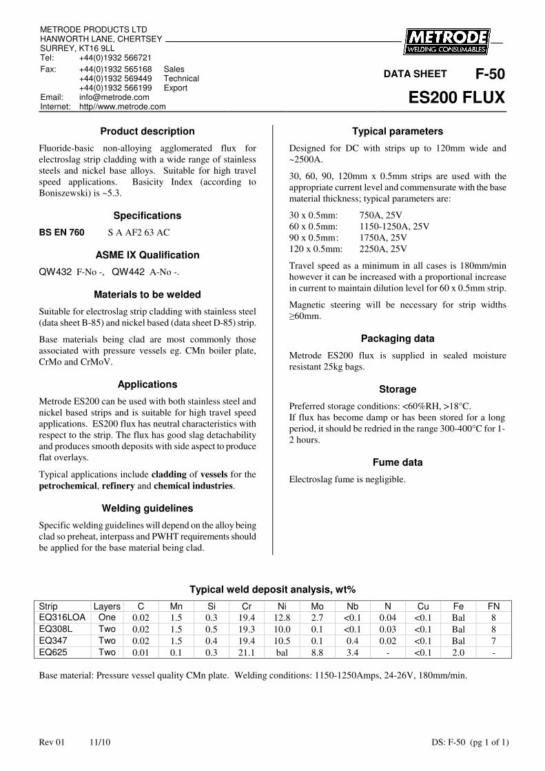
Product description
Fluoride-basic non-alloying agglomerated flux for
electroslag strip cladding with a wide range of stainless
steels and nickel base alloys. Suitable for high travel
speed applications. Basicity Index (according to
Boniszewski) is ~5.3.
Specifications
BS EN 760 S A AF2 63 AC
ASME IX Qualification
QW432 F-No -, QW442 A-No -.
Materials to be welded
Suitable for electroslag strip cladding with stainless steel
(data sheet B-85) and nickel based (data sheet D-85) strip.
Base materials being clad are most commonly those
associated with pressure vessels eg. CMn boiler plate,
CrMo and CrMoV.
Applications
Metrode ES200 can be used with both stainless steel and
nickel based strips and is suitable for high travel speed
applications. ES200 flux has neutral characteristics with
respect to the strip. The flux has good slag detachability
and produces smooth deposits with side aspect to produce
flat overlays.
Typical applications include cladding of vessels for the
petrochemical, refinery and chemical industries.
Welding guidelines
Specific welding guidelines will depend on the alloy being
clad so preheat, interpass and PWHT requirements should
be applied for the base material being clad.
Typical parameters
Designed for DC with strips up to 120mm wide and
~2500A.
30, 60, 90, 120mm x 0.5mm strips are used with the
appropriate current level and commensurate with the base
material thickness; typical parameters are:
30 x 0.5mm: 750A, 25V
60 x 0.5mm: 1150-1250A, 25V
90 x 0.5mm : 1750A, 25V
120 x 0.5mm: 2250A, 25V
Travel speed as a minimum in all cases is 180mm/min
however it can be increased with a proportional increase
in current to maintain dilution level for 60 x 0.5mm strip.
Magnetic steering will be necessary for strip widths
≥60mm.
Packaging data
Metrode ES200 flux is supplied in sealed moisture
resistant 25kg bags.
Storage
Preferred storage conditions: <60%RH, >18°C.
If flux has become damp or has been stored for a long
period, it should be redried in the range 300-400°C for 1-
2 hours.
Fume data
Electroslag fume is negligible.
Typical weld deposit analysis, wt%
Strip Layers C Mn Si Cr Ni Mo Nb N Cu Fe FN EQ316LOA One 0.02 1.5 0.3 19.4 12.8 2.7 <0.1 0.04 <0.1 Bal 8
EQ308L Two 0.02 1.5 0.5 19.3 10.0 0.1 <0.1 0.03 <0.1 Bal 8
EQ347 Two 0.02 1.5 0.4 19.4 10.5 0.1 0.4 0.02 <0.1 Bal 7
EQ625 Two 0.01 0.1 0.3 21.1 bal 8.8 3.4 - <0.1 2.0 -
Base material: Pressure vessel quality CMn plate. Welding conditions: 1150-1250Amps, 24-26V, 180mm/min.
Rev 00 11/10 DS: F-52 (pg 1 of 1)
METRODE PRODUCTS LTD HANWORTH LANE, CHERTSEY SURREY, KT16 9LL Tel: +44(0)1932 566721
Fax: +44(0)1932 565168 Sales DATA SHEET F-52 +44(0)1932 569449 Technical
+44(0)1932 566199 Export
ES400 FLUX Email: [email protected] Internet: http//www.metrode.com
Product description
Fluoride-basic non-alloying agglomerated flux for
electroslag strip cladding with a wide range of stainless
steels and nickel base alloys. Basicity Index (according to
Boniszewski) is ~4.2.
Specifications
BS EN 760 S A AF2 63 AC
ASME IX Qualification
QW432 F-No -, QW442 A-No -.
Materials to be welded
Suitable for electroslag strip cladding with stainless steel
(data sheet B-85) and nickel based (data sheet D-85) strip.
Base materials being clad are most commonly those
associated with pressure vessels eg. CMn boiler plate,
CrMo and CrMoV.
Applications
Metrode ES400 can be used with both stainless steel and
nickel based strips. ES400 flux has neutral characteristics
with respect to the strip. The flux has good slag
detachability and produces smooth deposits with side
aspect to produce flat overlays.
Typical applications include cladding of vessels for the
petrochemical, refinery and chemical industries.
Welding guidelines
Specific welding guidelines will depend on the alloy being
clad so preheat, interpass and PWHT requirements should
be applied for the material being clad.
Typical parameters
Designed for DC with strips up to 120mm wide and
~2500A.
30, 60, 90, 120mm x 0.5mm strips are used with the
appropriate current level and commensurate with the base
material thickness; typical parameters are:
30 x 0.5mm: 750A, 25V
60 x 0.5mm: 1150-1250A, 25V
90 x 0.5mm : 1750A, 25V
120 x 0.5mm: 2250A, 25V
Travel speed as a minimum in all cases is 180mm/min
however it can be increased with a proportional increase
in current to maintain dilution level for 60 x 0.5mm strip.
Magnetic steering will be necessary for strip widths
≥60mm.
Packaging data
Metrode ES400 flux is supplied in sealed moisture
resistant 25kg bags.
Storage
Preferred storage conditions: <60%RH, >18°C.
If flux has become damp or has been stored for a long
period, it should be redried in the range 300-400°C for 1-
2 hours.
Fume data
Electroslag fume is negligible.
Typical weld deposit analysis, wt%
Strip Layers C Mn Si Cr Ni Mo Nb N Cu Fe FN EQ308L Two 0.02 1.4 0.4 19.6 10.3 0.1 <0.1 0.03 0.1 Bal 8
EQ347 Two 0.02 1.4 0.3 19.8 10.6 0.1 0.4 0.03 0.1 Bal 8
EQ625 Two 0.01 0.1 0.4 21.8 Bal 8.9 3.3 - 0.1 2.1 -
Base material: Pressure vessel quality CMn plate. Welding conditions: 1150-1250Amps, 24-26V, 180mm/min.