Methods Progress Report 1 - projects.au.dkprojects.au.dk/fileadmin/D3_1b_Methods_Progress_Re… ·...
64
Grant Agreement: 644047 INtegrated TOol chain for model-based design of CPSs Methods Progress Report 1 Deliverable Number: D3.1b Version: 1.0 Date: 2015 Public Document http://into-cps.au.dk
Transcript of Methods Progress Report 1 - projects.au.dkprojects.au.dk/fileadmin/D3_1b_Methods_Progress_Re… ·...

Grant Agreement: 644047
INtegrated TOol chain for model-based design of CPSs
Methods Progress Report 1
Deliverable Number: D3.1b
Version: 1.0
Date: 2015
Public Document
http://into-cps.au.dk

D3.1b - Short Document Title (Public)
Contributors:
John Fitzgerald, UNEWCarl Gamble, UNEWRichard Payne, UNEWKen Pierce, UNEW
Editors:
Richard Payne, UNEW
Reviewers:
Christian König, TWTAndrey Sadovykh, STClaes Dühring Jaeger, AI
Consortium:
Aarhus University AU Newcastle University UNEWUniversity of York UY Linköping University LIUVerified Systems International GmbH VSI Controllab Products CLPClearSy CLE TWT GmbH TWTAgro Intelligence AI United Technologies UTRCSofteam ST
2
D3.1b - Short Document Title (Public)
Document History
Ver Date Author Description0.1 03-08-2015 Ken Pierce Draft structure of deliverable and responsibilities0.2 18-09-2015 Richard Payne Draft concepts added0.3 28-10-2015 Richard Payne Concepts updated for comments; version for use
by rest of project0.4 13-11-2015 Carl Gamble PROV and OSLC concepts, ontology and exam-
ples added0.5 13-11-2015 Richard Payne Traceability and provenance SotA added0.6 15-11-2015 Carl Gamble DSE and Traceability progress statements added0.7 16-11-2015 John Fitzgerald Introduction added0.8 16-11-2015 Ken Pierce Requirements and methods SotA added1.0 15-12-2015 Carl Gamble Internal review comments addressed
3

D3.1b - Short Document Title (Public)
Abstract
This document reports progress in Work package 3 (Multi-modelling Methods) in thefirst year of INTO-CPS. It also reports on the project’s survey of the state of the artin multi-modelling methods and heterogeneous system models, requirements engineering,and traceability and provenance for CPS design. An appendix is included that describesadditional preliminary work on the use of a combination of W3C Prov and OSLC speci-fications for traceability and provenance within the INTO-CPS technologies.
4
D3.1b - Short Document Title (Public)
Contents1 Introduction 6
2 Progress on WP3 Tasks 72.1 T3.1: Workflows . . . . . . . . . . . . . . . . . . . . . . . . . . . . . . . . 72.2 T3.2: Design Space Exploration . . . . . . . . . . . . . . . . . . . . . . . 102.3 T3.3: Provenance and Traceability . . . . . . . . . . . . . . . . . . . . . 112.4 T3.4: Guidelines . . . . . . . . . . . . . . . . . . . . . . . . . . . . . . . 122.5 T3.5: Pilot Case Studies . . . . . . . . . . . . . . . . . . . . . . . . . . . 12
3 State of the Art in Multi-model Methods 133.1 Requirements Engineering . . . . . . . . . . . . . . . . . . . . . . . . . . 143.2 Traceability and Provenance . . . . . . . . . . . . . . . . . . . . . . . . . 153.3 Design Space Exploration . . . . . . . . . . . . . . . . . . . . . . . . . . 163.4 Multi-modelling Methods and Hetereogeneous System Models . . . . . . 17
A Provenance and Traceability 20A.1 Introduction . . . . . . . . . . . . . . . . . . . . . . . . . . . . . . . . . . 20A.2 Prov Concepts . . . . . . . . . . . . . . . . . . . . . . . . . . . . . . . . . 20A.3 OSLC Specifications . . . . . . . . . . . . . . . . . . . . . . . . . . . . . 26A.4 Proposed INTO-CPS Traceability Ontology . . . . . . . . . . . . . . . . 32A.5 Robot Example . . . . . . . . . . . . . . . . . . . . . . . . . . . . . . . . 50A.6 UTRC Case Study Findings . . . . . . . . . . . . . . . . . . . . . . . . . 63A.7 Open Questions . . . . . . . . . . . . . . . . . . . . . . . . . . . . . . . . 64
5
D3.1b - Short Document Title (Public)
1 Introduction
This report describes the work undertaken in Year 1 of INTO-CPS in Work Package 3.New and prospective users of the INTO-CPS technologies should refer to the Deliverable3.1a Method Guidance 1 [FGPP15].
Work Package 3 (Multi-modelling Methods) in INTO-CPS aims to provide pragmaticmethods in the form of guidelines and patterns that support the emerging tool chain. Ourfocus is on ensuring that adoption of the tool chain is cost-effective by providing guidanceto help users determine the modelling technologies and patterns that best meet their needsand integrate with their work flows, taking into account their previous experience andprocesses. Ultimately, the full set of guidelines will cover the following areas:
• Workflows: multi-model construction from requirements capture in SysML, and theintegration of multi-models into existing development activities and processes.
• Design Space Exploration: the use of co-simulation to support consideration ofdesign options.
• Provenance and Traceability: methods for machine-assisted recording and mainte-nance of links between models, multi-models and other design artefacts.
The guidelines are underpinned by a common concept base, and are supported by agrowing set of pilot studies that can serve as benchmarks for the methods and tools andas illustrations for the tool chain’s capabilities.
The first release of the new multi-modelling tool chain was scheduled for late in Year 1.Our priority in WP3 was therefore to lay foundations for guidelines that will emerge fromexperience with the tool chain, and to provide specifications for functionality requiredof tools in the areas of Design Space Exploration (DSE) and traceability. Our specificobjectives were therefore as follows:
• To survey the state of the art in multi-modelling methods, so that the project couldidentify promising techniques and tools and position its own contributions. Thissurvey is reported in Section 3.
• To review the workflows in the case study partners and identify a candidate initialworkflow against which the INTO-CPS tool chain could be validated once released.This was undertaken in Task 3.1 and is reported in Section 2.1.
• To specify the Design Space Exploration (DSE) support that would ultimately berequired in the toolchain. This was undertaken in Task 3.2 and is reported inSection 2.2. The specification will be implemented in Task 5.1, for which Year 1progress is reported in Deliverable 5.1a [GHJ+15].
• To specify the traceability and provenance functionality that the toolchain shouldsupport. This would be implemented in Task 4.4 from Year 2 onwards. This wasundertaken in Task 3.3 and is reported in Section 2.3. Details of the support forprovenance features are given as Appendix A. The specification will be implementedin Task 4.4 from Year 2 onwards.
• To prepare a common concept base for the project, and deliver a first set of guide-lines for the construction of SysML models for multi-modelling given different entry
6
D3.1b - Short Document Title (Public)
points, domain knowledge and previous multi-modelling experience. This was un-dertaken in Task 3.4 and is reported in Section 2.4. The concept base is reportedin D3.1a Method Guidance 1 [FGPP15].
• To document initial pilot studies that illustrate various properties of CPSs andfeatures of the INTO-CPS technologies. This was undertaken in Task 3.5 and theinitial pilot studies are described in reported in Section 2.5.
2 Progress on WP3 Tasks
2.1 T3.1: Workflows
In the first year of the project, the focus of this task was to propose a candidate initialworkflow for the INTO-CPS technologies. Since the initial tool release was not planneduntil the end of this first year, full validation of the proposed workflow will not be achieveduntil later in the project. The main validation effort in this first year therefore entailedaligning the proposed workflows with both expected tool functionality, and in particularwith the existing practices, needs and expectations of the industrial case study owners.In order to achieve this, two surveys were carried out through questionnaires, with theresults informing the workflows work. These surveys were:
• the capabilities of the baseline tools
• the existing practices of the case study owners
The key result gathered from these surveys is that there will be no single, one-size-fits-all workflow for INTO-CPS. The scope of the tool chain is wide, and the experience andpractices of the industrial case study owners are diverse. For this reason, we developed theidea a set of activities carried out during CPS development, which then form workflowswhen grouped and linked.
We have identified an initial set of activities from the surveys, which are presented aspart of the method guidelines in Deliverable D3.1a [FGPP15]. These activities are alsolinked with the traceability artifacts described in Appendix A. From these activities weconsider how two existing workflows —based on responses to the survey of industrialcase study partners— could be enhanced by the INTO-CPS technologies. The work herealso informed the “Example Use Case for the INTO-CPS Technologies” which presentsa putative workflow that covers all aspects of the tool, though which is unlikely to befollowed to the letter in practice.
As experience is gained with the tool chain, and feedback received from industrial casestudy owners, further workflows will be developed and guidelines will be created thatadvise on when and how each workflow could be followed. This follows on from existingwork from the DESTECS baseline project [FLPV13a]. In the remainder of this sectionwe present the key findings from the survey of industrial case study owners.
7
D3.1b - Short Document Title (Public)
2.1.1 Summary of Results from the Survey of the Industrial Case StudyOwners
The survey of the industrial case study owners (CLE, AI, UTRC, and TWT) was un-dertaken using a questionnaire filled in by each of the partners. The questionnaire wasdivided into six sections:
• Workflows and Requirements
• Modelling and Simulation
• Tracebility, Provenance, Model Management
• Design Space Exploration
• Collaboration and Distribution
• Testing, Prototypes and Realisations
From these survey, along with informal discussions, we are able to establish a ‘profile’ foreach of the case study owners:
CLE Have well-established DE modelling practices based on formal proof and modelchecking. They have a small number of repeat customers. They are looking toINTO-CPS as a way to enhance their existing practice using simulation-based evi-dence.
AI Do not have well-established modelling- and simulation-based design processes. Theyare moving to developing both hardware and software in-house and are looking toadopt INTO-CPS to handle the complexity of CPS design.
UTRC Have well-established modelling practices in a variety of formalisms with someform of co-simulation. They have large libraries of reusable models. They are in-terested in using INTO-CPS to help establish better collaboration between existingdesign teams and to establish traceability through large CPS developments.
TWT Have well-established modelling practices focusing on software design using FMIco-simulation. They are interested in the hardware-in-the-loop testing based onINTO-CPS to improve confidence in designs.
Below we now summarise the key findings, commonalities and differences between thepartners that inform these profiles and the workflows presented in Deliverable D3.1a [FGPP15].
Workflows and Requirements UTRC and CLE have standardised workflows andadhere to standards in their domains (building automation and railways respectively). Inparticular UTRC has a clear workflow of tasks undertaken in order by different engineersand they wish to paralellise this. AI are working towards meeting functional safetystandard. UTRC and TWT follow high iterative approach to design. CLE follow a morelinear V-model.
Microsoft tools are widely used to capture and manage requirements, in particular Ex-cel (UTRC, CLE, TWT) and Word (AI). Additionally UTRC use the proprietary IBM
8
D3.1b - Short Document Title (Public)
Rational DOORS1.
UTRC and TWT identify difficulties in communicating terminology and vision betweenstakeholders when defining requirements for CPS designs. CLE and AI currently workwith stakeholders within their own domains and do not experience as many problemscurrently.
All partners identified that design changes are triggered by changes to stakeholder needs,problems encountered during design, and changes in budget. These can lead to overruns,increased project cost, and increased product costs. Responses include tracking issues andevolutions through tickets, and conducting impact and feasibility analysis and evolvingdesigns where appropriate.
Modelling and Simulation Models are manually created by all partners, thoughUTRC and CLE have some level of automatic model generation in specific circumstances.UTRC have a libraries of models for standard components and reuse is common prac-tice.
TWT mainly use CT models. AI have some CT models of mechanical components (FEM)and use electrical models for documentation. AI do not currently model software usingDE or state machines. CLE current modelling focus are software verification through DEmodels and state machines. UTRC use a wide variety of models, with current focus onMatlab, Modelica and state machines. Both TWT and UTRC do multi-domain modellingin Matlab/Simulink and co-simulate using FMI.
All parters identified areas where improved co-simulation would improve their workflows.All partners expressed a wish to have GUI interfaces for general use, with access tocommand-line scripting for specific use cases.
Tracebility, Provenance, Model Management The partners currently manage var-ious levels of traceability through diverse tools. CLE and UTRC use Excel, while TWTuse Fogbugs Project Tracker. Practices at AI are evolving from third party to in-housesoftware development, but some traceability can be established from documentation. Allpartners identified a need to store and manage diverse traceability artefacts (includingmodels, results, design notes and documentation).
UTRC use Mathworks’ Validation and Verification suite in some cases to trace require-ments between DOORS and models, but in general the diversity of engineering domainsand lack of tool support leads to long face-to-face meetings to establish agreement ontraceability. In addition high-level requirements can be realised through multiple compo-nents (or models thereof) leading to complex traceability needs.
The partners use various practices to help record authorship of artefacts including com-ments within models and records in version management software. All partners identifya need to produce certification evidence or customer documentation from traceabilityand/or provenance data recorded during a development.
1http://www-03.ibm.com/software/products/en/ratidoor
9
D3.1b - Short Document Title (Public)
Design Space Exploration Current practice in DSE is typically carried out manuallyand relies on the tacit knowledge and expertise of engineers. UTRC however have someinternals tools for carrying out DSE. No partner currently use exploration techniques thatreduce design space size (e.g. Taguchi tables, simulated annealing).
TWT currently explore both CT model variants and parameters within those variants.AI expressed a clear desire to do this as well, in addition to sweeping DE parameters suchas control thread periods.
Results are gathered in CSV/spreadsheets and are further processed in Excel and Matlab,and in Origin (UTRC) and Python (TWT). Visualisations include histograms, graphsand custom GUIs and are typically manually assessed through inspection, though TWTgenerate reports automatically.
Collaboration and Distribution All partners identified a need to pass artefacts be-tween design teams (models and model fragments, simulation results, textual information,requirements information, and test cases). Partners with existing modelling practices(UTRC, CLE, TWT) perform integration testing.
Use of distributed computing is not a core part of existing practice. TWT perform someremote simulations. Use of distributed computing is of interest to UTRC but currentsolutions are too complex.
Testing, Prototypes and Realisations Partners with existing modelling practices(UTRC, CLE, TWT) perform automated testing of models and use of models for gener-ating tests (and requirements in the case of TWT). These partners also use simulationresults to inform models in an iterative way. UTRC in particular have a large body ofexisting testing practices. Test cases are produced manually by AI and CLE. In addi-tion to testing, CLE and UTRC use other formal verification methods including modelchecking and formal proof.
Most partners (UTRC, CLE, AI) currently perform hardware- or software-in-the-loopsimulation, and TWT are interested in adopting this practice. Additionally code gener-ation is currently used by UTRC, TWT and CLE, typically targeting C.
2.2 T3.2: Design Space Exploration
In the first year of the DSE task the focus has been on assessing what the industrialpartners currently understand of DSE, what their aspirations are for DSE within theircase studies and what DSE approaches and algorithms should the INTO-CPS project aimto support. As outlined earlier in Section 2.1.1 the DSE approaches currently undertakenby the WP1 partners are manual and rely heavily on engineer expertise to both defineproduct parameters and to analyse results. While there will always be a need for engineerexpertise within the DSE methods to both define what aspects of a product design shouldbe varied and how to measure simulation outputs to evaluate and rank designs, the toolsupport within INTO-CPS aims to support the engineer in several ways:
10

D3.1b - Short Document Title (Public)
• reduce the workload in defining the parameters for and running multiple simula-tions to explore the design space by automating the configuration and launch ofsimulations;
• provide a range of DSE algorithms for the engineer to select from along with guid-ance about the suitability for different problem domains;
• provide templates and scripts to obtain objective measures of simulated CPS per-formance from the raw simulation results;
• support the use of both scripted ranking functions and pareto optimality to rankthe results of each design globally;
• reduce the total number of simulations required to have confidence in finding aglobally optimum solution by using design ranking and closed loop optimisationmethods.
The details of both the currently implemented DSE method and the set of proposedmethods may be found in D5.1a [GHJ+15]. This deliverable also contains the aspirationsof the WP1 partners for DSE along with comment on how the proposed methods willmeet them.
2.3 T3.3: Provenance and Traceability
The first year of provenance and traceability study has concentrated on exploring theboth the relations that will be important to the record within the INTO-CPS tool chainand also potential standard notations and specifications that may be used to representthem. Two distinct specifications have been identified to form the foundations for thethe provenance and traceability concepts within INTO-CPS, these specifications havethe benefits of both being open and free to use, and, in case of OSLC, have a widebase of industry support. The W3C PROV 2 model provides support for recording thetemporal relations between activities, entities and agents within a process. This supportsthe recording of, for example, links between simulation results and the models, platformsand configurations that produced them, this is important when generating documentationas part of a certification effort. To compliment this the relations specified by the OSLC 3
provides support for recording logical relations between objects within a data set. SoOSLC allows the linking of, for example, a submodel and a requirement that it is designedto satisfy, or from a simulation result to the requirement it provides evidence for.
The key concepts of both PROV and OSLC are presented in Appendix A of this documentalong with the proposed provenance and traceability ontology, which will form the basisfor data recorded by the various tools in the INTO-CPS tool chain. This appendixalso contains example applications of both PROV and OSLC being used to representmany of the document relations expected when using the INTO-CPS tool chain andworkflows.
2http://www.w3.org/TR/prov-overview/3http://open-services.net
11
D3.1b - Short Document Title (Public)
2.4 T3.4: Guidelines
In the first year of the project, the main aim of this task was to collate a concept basewhich will form a living document. The concept base [FGPP15] should be used as aresource for the project to ensure consistent terminology use when producing deliverablesand also in dissemination materials (e.g. conference papers). The concept base usedseveral inputs as baseline; primarily drawing on existing EU project outputs. Theseinclude:
TAMS4CPS TAMS4CPS4 is a EU H2020 coordination and support action, concernedwith an aim to identify research and development needs for modelling and simula-tion for CPSs. As such, the definitional framework produced in the project is a keyinput. Several general areas, such as definitions of CPSs, modelling and simulationwere valuable inputs.
DESTECS The DESTECS5 EU project was concerned with the co-modelling and co-simulation of embedded systems. As such, concepts including models, simulationand co-simulation were of use. However, as DESTECS focussed on embedded sys-tems, several of the terms required lifting to the CPS domain. Several other tech-nologies and tools used in INTO-CPS were not covered in DESTECS.
COMPASS The COMPASS6 FP7 project focussed on the modelling and analysis ofSystems of Systems (SoSs). SoSs exhibit several characteristics in common withCPSs, and as the COMPASS project used several technologies in common withINTO-CPS baseline (SysML, RT-Tester) the COMPASS concept and terminologybase was of use.
The concept base, presented in Deliverable D3.1a [FGPP15], was circulated to the projectpartners for input to determine any areas of disagreement and for reference. Severalterms were addressed, but at the time of writing, no major concerns have been raised.The concept base will therefore be used to inform a hyperlinked resource for the projectin the next phases of the project.
The second aim of the task is to produce guidelines for multi-modelling. In the first year,we concentrated on guidelines for SysML modelling, presented in D3.1a [FGPP15]. Theseguidelines focus on the construction of SysML models for multi-modelling given differententry points, domain knowledge and previous multi-modelling experience. The guidelinesmake use of the INTO-CPS SysML profile in Deliverable D2.1a [APCB15].
2.5 T3.5: Pilot Case Studies
In Deliverable D3.4 [FGP+15] we present a collection of pilot studies that illustrate differ-ent aspects of the INTO-CPS baseline and future technologies. These studies were chosenagainst selection criteria in terms of properties of CPSs and their ability to demonstratethe features of the INTO-CPS technologies. We also ensure that the studies must be easilyexplained and material should be made available for teaching/training purposes.
4http://www.tams4cps.eu5http://www.destecs.org6http://www.compass-research.eu
12
D3.1b - Short Document Title (Public)
In this section, we outline those CPS properties and INTO-CPS technologies, and describehow the chosen pilot studies meet the criteria. It is important to note that in this firstyear, we don’t expect to have complete coverage of the criteria. Therefore in D3.4 wepropose a roadmap for the next 12 months of case study and example development totest and demonstrate upcoming INTO-CPS technologies.
The INTO-CPS concept base in [FGPP15], describes CPSs as being “ICT systems (sens-ing, actuating, computing, communication, etc.) embedded in physical objects, inter-connected (including through the Internet) and providing citizens and businesses with awide range of innovative applications and services”. As such, the pilot studies should ex-hibit cyber, physical and network communication characteristics. The pilot studies in thisdocument address mainly address the first two of these CPS characteristics. The reasonfor this is that these examples test the baseline tools, which emphasise the modelling ofcyber and physical systems and the co-modelling of these in embedded systems.
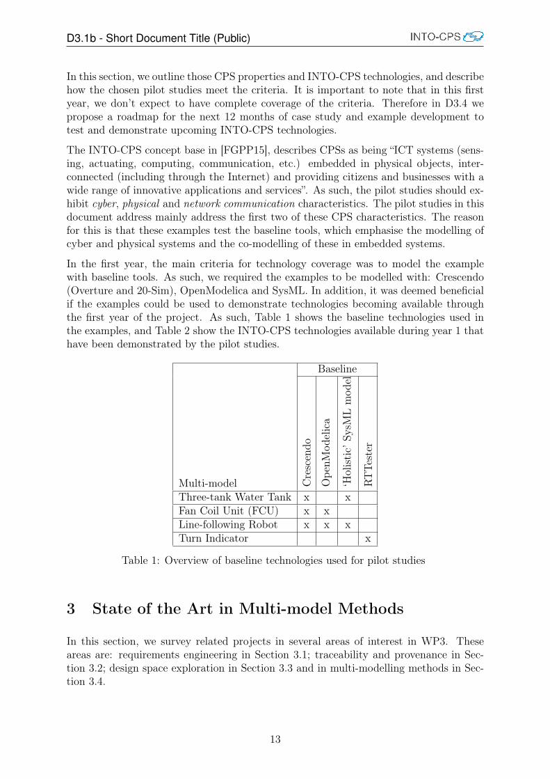
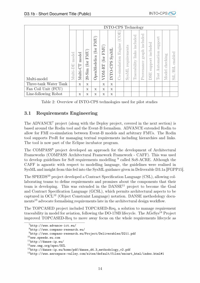
In the first year, the main criteria for technology coverage was to model the examplewith baseline tools. As such, we required the examples to be modelled with: Crescendo(Overture and 20-Sim), OpenModelica and SysML. In addition, it was deemed beneficialif the examples could be used to demonstrate technologies becoming available throughthe first year of the project. As such, Table 1 shows the baseline technologies used inthe examples, and Table 2 show the INTO-CPS technologies available during year 1 thathave been demonstrated by the pilot studies.
Baseline
Multi-model Crescendo
Ope
nMod
elica
‘Holistic’
SysM
Lmod
el
RTTe
ster
Three-tank Water Tank x xFan Coil Unit (FCU) x xLine-following Robot x x xTurn Indicator x
Table 1: Overview of baseline technologies used for pilot studies
3 State of the Art in Multi-model Methods
In this section, we survey related projects in several areas of interest in WP3. Theseareas are: requirements engineering in Section 3.1; traceability and provenance in Sec-tion 3.2; design space exploration in Section 3.3 and in multi-modelling methods in Sec-tion 3.4.
13
D3.1b - Short Document Title (Public)
INTO-CPS Technology
Multi-model Multi-D
Emod
el
Multi-C
Tmod
el
20-Sim
(for
FMU)
Ope
nMod
elica(for
FMU)
VDM-RT
(for
FMU)
INTO-C
PSSy
sML
Co-simulationEng
ine(C
OE)
SysM
Lrequ
irem
ents
Traceabilitylin
ksinclud
ed
Provena
ncegrap
hinclud
ed
DSE
supp
ortinclud
ed
Test
Autom
ationsupp
ort
Mod
elchecking
SiL/
HiL
enab
led
Three-tank Water Tank x x x xFan Coil Unit (FCU) x x x xLine-following Robot x x x x x
Table 2: Overview of INTO-CPS technologies used for pilot studies
3.1 Requirements Engineering
The ADVANCE7 project (along with the Deploy project, covered in the next section) isbased around the Rodin tool and the Event-B formalism. ADVANCE extended Rodin toallow for FMI co-simulation between Event-B models and arbitrary FMUs. The Rodintool supports ProR for managing textual requirements including hierarchies and links.The tool is now part of the Eclipse incubator program.
The COMPASS8 project developed an approach for the development of ArchitecturalFrameworks (COMPASS Architectural Framework Framework - CAFF). This was usedto develop guidelines for SoS requirements modelling 9 called SoS-ACRE. Although theCAFF is agnostic with respect to modelling language, the guidelines were realised inSysML and insight from this fed into the SysML guidance given in Deliverable D3.1a [FGPP15].
The SPEEDS10 project developed a Contract Specification Language (CSL), allowing col-laborating teams to define requirements and promises about the components that theirteam is developing. This was extended in the DANSE11 project to become the Goaland Contract Specification Language (GCSL), which permits architectural aspects to becaptured in OCL12 (Object Constraint Language) notation. DANSE methodology docu-ments13 advocate formalising requirements late in the architectural design workflow.
The TOPCASED project included TOPCASED-Req, a solution to manage requirementtraceability in model for aviation, following the DO-178B lifecycle. The AGeSys14 Projectimproved TOPCASED-Req to move away focus on the whole requirements lifecycle as
7http://www.advance-ict.eu/8http://www.compass-research.eu/9http://www.compass-research.eu/Project/Deliverables/D211.pdf
10www.speeds.eu.com11http://danse-ip.eu/12www.omg.org/spec/OCL13http://danse-ip.eu/home/pdf/danse_d4.3_methodology_v2.pdf14http://www.aerospace-valley.com/sites/default/files/encart_html/index.html#1
14
D3.1b - Short Document Title (Public)
a new tool called becomes ReqCycle. TOPCASED and ReqCycle now form part of thePolarSys15 open-source tools for embedded systems.
The META tool being developed under DARPA AVM (Adaptive Vehicle Make) pro-gramme makes use of the CyPhyML meta language. In terms of requirements they focuson “executable requirements” that are quantifiable tests that can be automatically checkedagainst models or implementations. This has been demonstrated in OpenModelica.
The ENOSYS16 project targeted design space exploration for FPGA design, using theMARTE UML profile for high-level specification. The Modelio tool was used in thisproject and therefore INTO-CPS already benefits from this research.
The MODRIO17 and Openprod projects investigated mapping requirements to Open-Modelica. Again as OpenModelica is a baseline tool for INTO-CPS, we can leveragethese results as our technologies develop.
3.2 Traceability and Provenance
The Deploy18 project presents an approach to traceability from informal requirementsto a formal model in the Event-B notation [Pro12]. In contrast to INTO-CPS, Deployconcentrate on traceability from complete requirements to only state-based models, ratherthan the flexible tracing of system engineering model elements. As with the INTO-CPSproject, Deploy see tool support as critical for traceability, and produce an integrationof the ProR platform for requirements engineering and the Rodin platform for Event-B modelling. The ADVANCE 19 project continued this development. In addition, incollaboration with the VERDE project, a traceability solution was developed betweenEclipse-based tools such as ProR and Topcased20 for SysML. This uses a concept ofTracepoints to link to Eclipse model elements [GJ11].
In the OPENCOSS 21 project traceability is used for evidence management and impactanalysis of requirement through to safety cases [vdBLK+15]. Several traceability rela-tionships are defined linking ‘artefacts’. The traceability links are then used as part ofimpact analysis using the Evidence Management tool support produced in the project.Using SVN repositories, a user must manually add artefacts, linked to resources in a SVNrepository and record the necessary traces. This is in contrast to INTO-CPS which aimsto have a central traceability and management tool which will be integrated with theINTO-CPS tool chain, and a greater number of traceability links covering a modellingand simulation.
In the COMPASS 22 project, requirements were modelled and there was support for trace-ability between models. Explicit traceability mechanisms supporting forwards and back-wards tracing were not a focus of the project, however a traceability pattern was produced
15https://www.polarsys.org/16http://www.enosys-project.eu/17https://www.modelica.org/external-projects/modrio18http://www.deploy-project.eu19www.advance-ict.eu/20https://www.polarsys.org/topcased21http://www.opencoss-project.eu22http://compass-research.eu
15
D3.1b - Short Document Title (Public)
for SysML SoS engineering [PHP+14]. It would appear that provenance metadata couldbe captured within the existing framework, but this was not a subject of study in theproject.
In common with INTO-CPS, the SPRINT 23 project uses OSLC to link models formvarious tools, from requirements in DOORS through to architectural models using IBMRhapsody and Simulink and Modelica system models. Although not explicitly used fortraceability or model management, INTO-CPS should make use of project results in theimplementation and use of OSLC.
The Openprod24 project lists an outcome as including “precise requirements capture andtraceability based on behavior trees integrated with Modelica/UML in Eclipse; ontology-based generic 2D/3D graphic modeling and database coupling”. However, we were unableto locate public deliverables.
In analysing the state of the art, the CPSoS 25 EU support action determined that inthe automotive sectors, the collecting and managing maintenance and diagnostic data,dealing with heterogeneous data considering provenance and quality of data is a challengeto be addressed in the next 5 years [PEF+14]. The project also recognises the need fortraceability from requirements through to implementation, but in their state of the art ,they do not appear to identify any projects which tackle this issue [TPR+15].
In the MODRIO26 project, traceability links were proposed between requirements, de-signs and scenarios for the purposes of requirement evaluation (understanding conflictedand redundant requirements) and impact analysis. A prototype traceability view wasproduced for ModelicaML, but in not extensible across a tool chain [Sch13].
The Acosar 27 project, starting in 2015, aims to integrate real-time systems into simulationenvironments. The project description concerns requirements, simulation and integration.It is not clear if traceability is a focus, however, results should be monitored.
TAPPS 28 are developing an open end-to-end tool chain for developing and deploying CPSApps. It in unclear whether this will include traceability, and therefore project outputsshould be monitored.
3.3 Design Space Exploration
A comprehensive overview of the state of the art in DSE is provided in Deliverable5.1a [GHJ+15].
23http://www.sprint-iot.eu24http://www.ida.liu.se/labs/pelab/OpenProd/25http://www.cpsos.eu/26https://www.modelica.org/external-projects/modrio27http://www.acosar.eu28http://www.acosar.eu
16
D3.1b - Short Document Title (Public)
3.4 Multi-modelling Methods and Hetereogeneous System Mod-els
The CRYSTAL29 project (Artemis) is developing a framework for that allows OEMs tointegrate tools for embedded systems development, based around the Crystal Interop-erability Specification (IOS) V2.0, which is an extension of OSLC. The project extendswork from previous ARTEMIS projects CESAR, iFEST and MBAT. Their method guid-ance is based on “Generic Engineering Methods” which are similar to the activities andworkflows described in Deliverable D3.1a [FGPP15]. INTO-CPS should work to alignour workflows with those identified by CRYSTAL, keeping in mind that the needs of theindustrial case study owners is the first priority.
The TERESA30 project aimed to provide guidelines for software process engineers to de-fine trusted computing engineering processes in various domains (automotive, home con-trol, industrial control, and metering) and in resource-constrained environments. INTO-CPS should investigate how these guidelines are presented and if they can inform any ofthe guidelines work for the INTO-CPS technologies.
Ptolemy II31 offers a heterogeneous simulation framework for modeling DE and CT com-ponents within one model. The iCyPhy32 is a pre-competitive industry-academic partner-ship pursuing well-founded methods for engineering of cyber-physical systems, includingimprovements to Ptolemy II. INTO-CPS should consider the gaps in current and researchneeds identified in Fisher et al. [FJLM14].
29http://www.crystal-artemis.eu/30http://www.teresa-project.org/31http://ptolemy.eecs.berkeley.edu/32http://www.icyphy.org/
17
D3.1b - Short Document Title (Public)
References
[APCB15] Nuno Amalio, Richard Payne, Ana Cavalcanti, and Etienne Brosse. Founda-tions of the SysML profile for CPS modelling. Technical report, INTO-CPSDeliverable, D2.1a, December 2015.
[FGP+15] John Fitzgerald, Carl Gamble, Richard Payne, Ken Pierce, and Jörg Brauer.Examples Compendium 1. Technical report, INTO-CPS Deliverable, D3.4,December 2015.
[FGPP15] John Fitzgerald, Carl Gamble, Richard Payne, and Ken Pierce. MethodGuidelines 1. Technical report, INTO-CPS Deliverable, D3.1a, December2015.
[FJLM14] Amit Fizher, Clas A. Jacobson, Edward A. Lee, and Richard M. Murray.Industrial Cyber-Physical Systems – iCyPhy. In M. Aiguier et al., editor,Complex Systems Design and Management, pages 21–37. Springer, January2014.
[FLPV13a] John Fitzgerald, Peter Gorm Larsen, Ken Pierce, and Marcel Verhoef. AFormal Approach to Collaborative Modelling and Co-simulation for Embed-ded Systems. To appear in Mathematical Structures in Computer Science,2013. Outdated by [FLPV13b].
[FLPV13b] John Fitzgerald, Peter Gorm Larsen, Ken Pierce, and Marcel Verhoef. AFormal Approach to Collaborative Modelling and Co-simulation for Embed-ded Systems. Mathematical Structures in Computer Science, 23(4):726–750,2013.
[GHJ+15] Carl Gamble, Francois Hantry, Claes Dühring Jæger, Christian König,Alie El din Madie, and Richard Payne. Design Space Exploration in theINTO-CPS Platform. Technical report, INTO-CPS Deliverable, D5.1a, De-cember 2015.
[GJ11] Andreas Graf and Michael Jastram. Requirements, traceability and dslsin eclipse with the requirements interchange format (rif/reqif). Technicalreport, 2011. http://deploy-eprints.ecs.soton.ac.uk/307/1/mbees2011.pdf.
[LPH+15] Peter Gorm Larsen, Ken Pierce, Francois Hantry, Joey W. Coleman, SuneWolff, Kenneth Lausdahl, Marcel Groothuis, Adrian Pop, Miran Hasanagić,Jörg Brauer, Etienne Brosse, Carl Gamble, Simon Foster, and Jim Wood-cock. Requirements Report year 1. Technical report, INTO-CPS Deliver-able, D7.3, December 2015.
[PEF+14] Radoslav Paulen, Sebastian Engell, Wan Fokkink, Haydn Thompson, Dag-mar Marron, and Svetlana Klessova. Report about the first meeting of theWorking Groups. Technical Report D1.2, EC FP7 project 611115 CPSoS,February 2014.
[PHP+14] Simon Perry, Jon Holt, Richard Payne, Jeremy Bryans, Claire Ingram, Al-varo Miyazawa, Luís Diogo Couto, Stefan Hallerstede, Anders Kaels Mal-mos, Juliano Iyoda, Marcio Cornelio, and Jan Peleska. Final Report on
18
D3.1b - Short Document Title (Public)
SoS Architectural Models. Technical report, COMPASS Deliverable, D22.6,September 2014. Available at http://www.compass-research.eu/.
[Pro12] Deploy Project. Deploy methods: Final report. Technical Report D6.6, ECproject 214158 Deploy, April 2012.
[Sch13] Wladimir Schamai. Model-Based Verification of Dynamic System Be-havior against Requirements: Method, Language, and Tool. PhD thesis,Linkoping University, Department of Computer and Information Science.Linkoping University, The Institute of Technology., 2013. http://liu.diva-portal.org/smash/get/diva2:654890/FULLTEXT01.pdf.
[TPR+15] Haydn Thompson, Radoslav Paulen, Michel Reniers, Christian Sonntag,and Sebastian Engell. Analysis of the State-of-the-Art and Future Chal-lenges in Cyber-physical Systems of Systems. Technical Report D2.4, ECFP7 project 611115 CPSoS, February 2015.
[vdBLK+15] Mark van den Brand, Luna Yaping Luo, Martijn Klabbers, Giorgio Taglia-ferri, Vincenzo Manni Andrea Critelli, Jose Luis de la Vara, Sunil Nair,Carlo Ieva, and Rodolphe Arthaud. Evidence management service in-frastructure: Methodological guide. Technical Report D6.7, OPENCOSSProject, 2015.
19
D3.1b - Short Document Title (Public)
A Provenance and Traceability
A.1 Introduction
Traceability and Provenance to support requirements engineering, certification efforts andmodel management will be key features for INTO-CPS. In this appendix we present theinitial work on using the W3C Prov concepts to support model management. The basicconcepts of Prov are introduced first, before candidate specifications from the OSLC arepresented. The PROV concepts and a selection of the OSLC relations are then combinedinto a proposed INTO-CPS ontology. Examples of how these concepts may be used torepresent a range of anticipated activities within an INTO-CPS work flow are presented.We then discuss some findings found when trying to apply Prov to the UTRC WP1 casestudy before touching upon some open questions.
A.2 Prov Concepts
Provenance is the information about who was involved in producing something, the ac-tivities that took place and entities that were involved. The W3C PROV working grouphave defined a family of documents that describes the concepts in this domain and two inparticular have been used in the development of the provenance and traceability work inINTO-CPS. The provenance ontology (PROV-O)33 defines the concepts that are repre-sented by PROV and this heavily influenced the construction of our traceability ontologypresented later (Section| A.4). Alongside this the provenance notation (PROV-N)34 hasbeen used to produce concrete examples of the provenance data that would need tobe recorded and from this we obtain the majority of the graphical views in this ap-pendix.
In the following subsections we will present the main concepts of PROV-O, focussingon their relations and present examples in both the PROV-N notation and graphicalform.
A.2.1 Entities, Activities and Agents
There are three node types in a Prov graph these are entity, activity and agent.
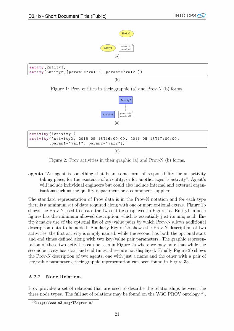
entities “An entity is a physical, digital, conceptual, or other kind of thing with somefixed aspects; entities may be real or imaginary”. In the case of INTO-CPS, thiswould include requirements documents, models, simulation configuration files, sim-ulation results and the simulators themselves.
activities “An activity is something that occurs over a period of time and acts uponor with entities; it may include consuming, processing, transforming, modifying,relocating, using, or generating entities”. In INTO-CPS activities will include,modelling, simulation and co-simulation;
33http://www.w3.org/TR/prov-o/34http://www.w3.org/TR/prov-n/
20
D3.1b - Short Document Title (Public)
Entity1
Entity2
param1: val1
param2: val2
(a)�entity(Entity1)entity(Entity2 ,[ param1="val1", param2="val2"])� �
(b)
Figure 1: Prov entities in their graphic (a) and Prov-N (b) forms.
Activity1
Activity2
param1: val1
param2: val2
(a)�activity(Activity1)activity(Activity2 , 2015 -05 -18 T16 :00:00 , 2011 -05 -18 T17 :00:00 ,
[param1="val1", param2="val2"])� �(b)
Figure 2: Prov activities in their graphic (a) and Prov-N (b) forms.
agents “An agent is something that bears some form of responsibility for an activitytaking place, for the existence of an entity, or for another agent’s activity”. Agent’swill include individual engineers but could also include internal and external organ-isations such as the quality department or a component supplier.
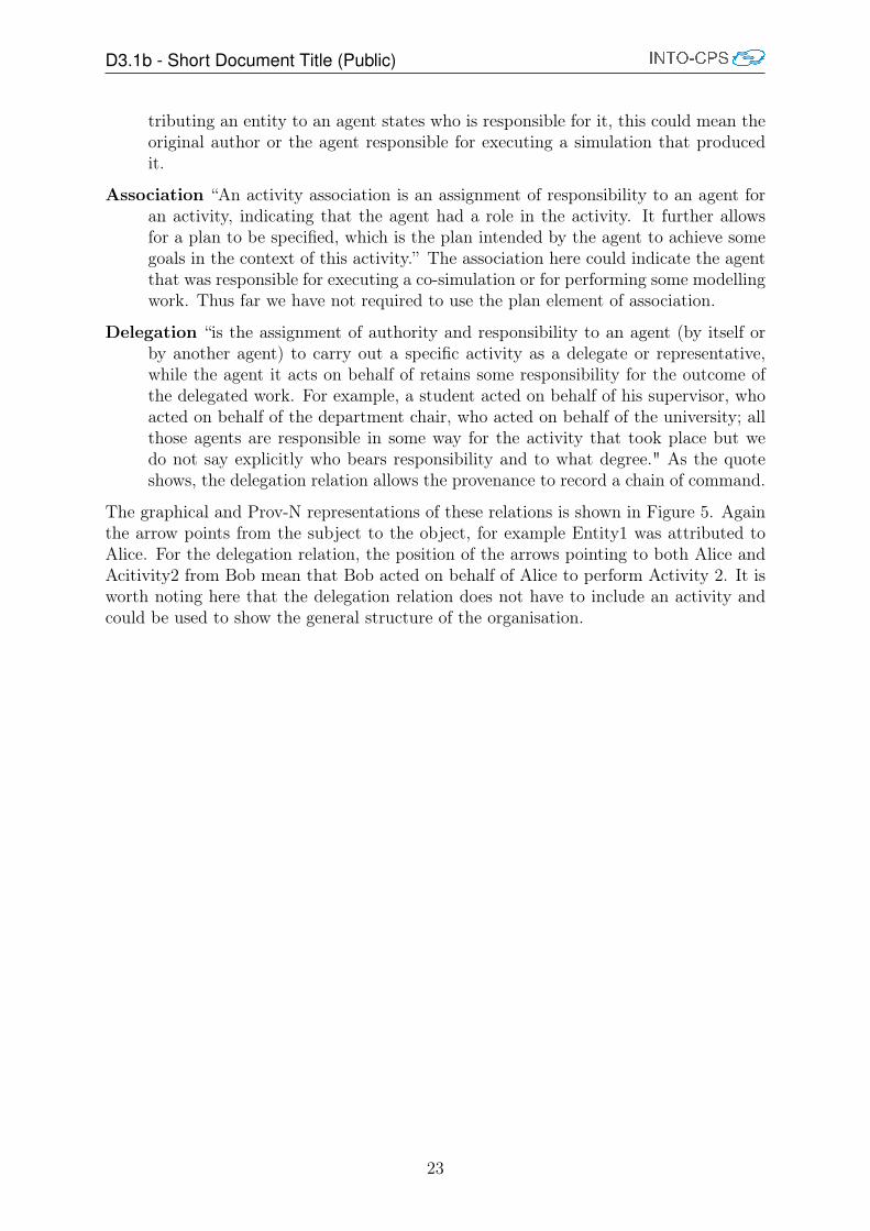
The standard representation of Prov data is in the Prov-N notation and for each typethere is a minimum set of data required along with one or more optional extras. Figure 1bshows the Prov-N used to create the two entities displayed in Figure 1a. Entity1 in bothfigures has the minimum allowed description, which is essentially just its unique id. En-tity2 makes use of the optional list of key/value pairs by which Prov-N allows additionaldescription data to be added. Similarly Figure 2b shows the Prov-N description of twoactivities, the first activity is simply named, while the second has both the optional startand end times defined along with two key/value pair parameters. The graphic represen-tation of these two activities can be seen in Figure 2a where we may note that while thesecond activity has start and end times, these are not displayed. Finally Figure 3b showsthe Prov-N description of two agents, one with just a name and the other with a pair ofkey/value parameters, their graphic representation can been found in Figure 3a.
A.2.2 Node Relations
Prov provides a set of relations that are used to describe the relationships between thethree node types. The full set of relations may be found on the W3C PROV ontology 35,
35http://www.w3.org/TR/prov-o/
21

D3.1b - Short Document Title (Public)
Alice
Bob
param1: val1
param2: val2
(a)�agent(Alice)agent(Bob ,[ param1="val1", param2="val2"])� �
(b)
Figure 3: Prov agents in their graphic (a) and Prov-N (b) forms.
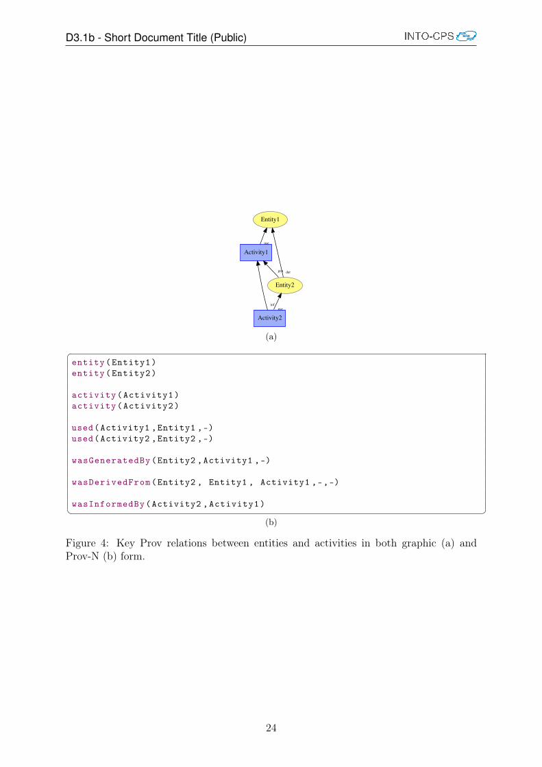
but in the example traces we have produced thus far we have only needed a subset ofthese. Starting then by considering only the entity and activity nodes, the key relationsare:
used “Usage is the beginning of utilizing an entity by an activity. Before usage, theactivity had not begun to utilize this entity and could not have been affected bythe entity.” As the quote implies, activities use entities, so we can imagine thatsimulation uses a model file.
was generated by “Generation is the completion of production of a new entity by anactivity. This entity did not exist before generation and becomes available for usageafter this generation.” Entities are generated by activities, so we could say that asimulation result file was generated by the simulation activity.
was derived from “A derivation is a transformation of an entity into another, an updateof an entity resulting in a new one, or the construction of a new entity based on apre-existing entity.” An ‘entity ← was derived from ← entity’ relation can reduceambiguity found in an ‘entity ← used ← activity ← was generated by ← entity’chain when there are multiple entities on both ends of the chain. For example ifa modelling activity uses two input models and produces two output models, it isnot clear which input models influenced which output models.
was informed by “Communication is the exchange of an entity by two activities, oneactivity using the entity generated by the other.” This relation can be used toindicate communication between activities where the data communicated is eitherinsignificant or transient. For example, this could be used to describe and OSLCexchange between two tools or the FMI communications between simulators andthe COE.
The graphical and prov-n representations of these relations can be seen in Figure 4. It isworth noting at this point that the arrows point backwards in time and from the subjectto the object. For example when recording the relation file X was generated by activityY, the arrow will point to the activity.
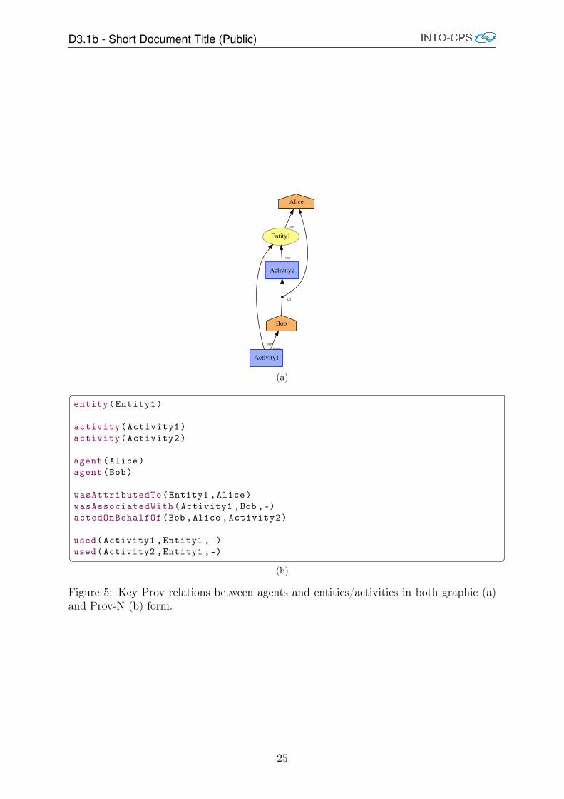
Prov also includes relations to record responsibility for actions and entities, there are onlythree of these and all have proved to be of use when considering provenance examples forINTO-CPS:
Attribution “Attribution is the ascribing of an entity to an agent.” Very simply, at-
22
D3.1b - Short Document Title (Public)
tributing an entity to an agent states who is responsible for it, this could mean theoriginal author or the agent responsible for executing a simulation that producedit.
Association “An activity association is an assignment of responsibility to an agent foran activity, indicating that the agent had a role in the activity. It further allowsfor a plan to be specified, which is the plan intended by the agent to achieve somegoals in the context of this activity.” The association here could indicate the agentthat was responsible for executing a co-simulation or for performing some modellingwork. Thus far we have not required to use the plan element of association.
Delegation “is the assignment of authority and responsibility to an agent (by itself orby another agent) to carry out a specific activity as a delegate or representative,while the agent it acts on behalf of retains some responsibility for the outcome ofthe delegated work. For example, a student acted on behalf of his supervisor, whoacted on behalf of the department chair, who acted on behalf of the university; allthose agents are responsible in some way for the activity that took place but wedo not say explicitly who bears responsibility and to what degree." As the quoteshows, the delegation relation allows the provenance to record a chain of command.
The graphical and Prov-N representations of these relations is shown in Figure 5. Againthe arrow points from the subject to the object, for example Entity1 was attributed toAlice. For the delegation relation, the position of the arrows pointing to both Alice andAcitivity2 from Bob mean that Bob acted on behalf of Alice to perform Activity 2. It isworth noting here that the delegation relation does not have to include an activity andcould be used to show the general structure of the organisation.
23
D3.1b - Short Document Title (Public)
Activity1
Entity1
use
Activity2
inf
Entity2
use
gen der
(a)�entity(Entity1)entity(Entity2)
activity(Activity1)activity(Activity2)
used(Activity1 ,Entity1 ,-)used(Activity2 ,Entity2 ,-)
wasGeneratedBy(Entity2 ,Activity1 ,-)
wasDerivedFrom(Entity2 , Entity1 , Activity1 ,-,-)
wasInformedBy(Activity2 ,Activity1)� �(b)
Figure 4: Key Prov relations between entities and activities in both graphic (a) andProv-N (b) form.
24
D3.1b - Short Document Title (Public)
Activity1
Entity1
use
Bob
assoc
Activity2
use
Alice
att
del
(a)�entity(Entity1)
activity(Activity1)activity(Activity2)
agent(Alice)agent(Bob)
wasAttributedTo(Entity1 ,Alice)wasAssociatedWith(Activity1 ,Bob ,-)actedOnBehalfOf(Bob ,Alice ,Activity2)
used(Activity1 ,Entity1 ,-)used(Activity2 ,Entity1 ,-)� �
(b)
Figure 5: Key Prov relations between agents and entities/activities in both graphic (a)and Prov-N (b) form.
25

D3.1b - Short Document Title (Public)
A.3 OSLC Specifications
The OSLC contains multiple specifications covering areas including requirements man-agement, change management, asset management and others. This subsection is furtherdivided into a series of sub-sub-sections, the first five (Appendices A.3.1 – A.3.5) compilelists of the main relations in each of these specifications along with a verbatim copy ofthe description of the relation taken from the OSLC specification documents. It is fairto say that the description text given by the OSLC specification for many of the rela-tions is somewhat loose and open to some interpretation and so it is suggested that thereader does not dwell upon the detail of the descriptions in these subsections. The finalsubsubsection, Appendix A.3.6, contains a list of the relations that are currently selectedfor adoption for the INTO-CPS traceability ontology during the next year of the project,here we include our interpretation of the meaning of each adopted term.
Some of the specifications below make reference to the Dublin Core using the prefix‘dcterms:’, this is an initiative to standardise many of the terms that are commonly usedwhen identifying meta-data. A complete list of the meta-data terms they define may befound at their website36.
A.3.1 Requirements Management (oslc_rm) v2.0
The OSLC requirements management specification considers the relations between re-quirements artefacts themselves and also between requirements and model elements thatvalidate or satisfy them. The full specification may be found at the url in the foot-note.37.
oslc_rm:elaboratedBy The subject is elaborated by the object. For example, a col-lection of user requirements elaborates a business need, or a model elaborates acollection of system requirements.
oslc_rm:elaborates The object is elaborated by the subject.
oslc_rm:specifiedBy The subject is specified by the object. For example, a modelelement might make a requirement collection more precise.
oslc_rm:specifies The object is specified by the subject.
oslc_rm:affectedBy The subject is affected by the object, for example, a defect orissue.
oslc_rm:trackedBy Resource, such as a change request, which manages this require-ment collection.
oslc_rm:implementedBy Resource, such as a change request, which implements thisrequirement collection.
oslc_rm:validatedBy Resource, such as a test plan, which validates this requirementcollection.
36http://dublincore.org/documents/dcmi-terms/37http://open-services.net/bin/view/Main/RmSpecificationV2?rev=57
26
D3.1b - Short Document Title (Public)
oslc_rm:satisfiedBy The subject is satisfied by the object. For example, a collectionof user requirements is satisfied by a requirement collection of system requirements.
oslc_rm:satisfies The object is satisfied by the subject.
oslc_rm:decomposedBy The subject is decomposed by the object. For example, acollection of business requirements is decomposed by a collection of user require-ments.
oslc_rm:decomposes The object is decomposed by the subject.
oslc_rm:constrainedBy The subject is constrained by the object. For example, arequirement collection is constrained by a requirement collection.
oslc_rm:constrains The object is constrained by the subject.
A.3.2 Architecture Management (oslc_am) V3.0
The OSLC architecture management specification aims to represent the relations betweenarchitectural elements in general allowing the description of enterprise architectures, so-lution architectures and technical architectures. It has concepts that overlap with thosein the requirements management specification. Only a small subset is presented below,the full specification may be found at the url in the footnote38.
oslc_am:refines This resource is a refinement of the referenced resource. For example,a Use Case scenario might be a refinement of a textual requirement that describesthe interaction.
oslc_am:satisfies This resource satisfies a requirement (the referenced resource). Forexample a UML Component satisfies a requirement to provide some type of func-tionality.
oslc_am:verifies A dependency from a model element to a requirement that determineswhether a system fulfills the requirement. For example a Sequence diagram verifiesa requirement that describes a protocol.
dm:derives The model element derives from a requirement.
dm:elaborates The model element elaborates a change request.
A.3.3 Asset Management (oslc_asset) V2.0
The OSLC asset management specification allows the relationships to an organisation’sassets and the asset’s lifecycle to be recorded. An asset is anything that provides valuethrough reference or reuse and so this specification may be useful when recording theprovenance of simulation results where hardware assts are used (HiL)39.
38http://open-services.net/wiki/architecture-management/OSLC-Architecture-Management-Specification-Version-3.0/
39http://open-services.net/wiki/asset-management/OSLC-Asset-Management-2.0-Specification/
27
D3.1b - Short Document Title (Public)
oslc_asset:guid An identifier for the asset. Assigned by the service provider whena resource is created. Different versions of the same asset will share the sameidentifier.
oslc_asset:version The version of the asset. Possible values may include ’1.0’, ’2.0’,etc.
dcterms:abstract Short description or often a single line summary of the resource
dcterms:type The type of the asset based on values defined by the service provider.This specification does not define the resource for this property, however it shouldcontain a dcterms:title property.
oslc_asset:state sed to indicate the state of the asset based on values defined by theservice provider. This specification does not define the resource for this property,however it should contain a dcterms:title property.
oslc_asset:categorization A categorization to classify an asset. The category schemavalues are defined by the service provider. This specification does not define theresource for this property, however it should contain a dcterms:title property.
oslc_asset:manufacturer The name of the asset manufacturer.
oslc_asset:model The value of the asset model.
oslc_asset:serialNumber The serial number assigned by the asset manufacturer.
oslc_asset:tag Specifies the asset tag value for an Asset. Asset tags are typically humanreadable labels. For hardware assets, these tags are durable, securely attached toequipment, and may also be readable by barcode and/or RFID.
oslc_asset:artifact must reference an ’oslc_asset:Artifact’ An Artifact fragment con-tained in this Asset resource.
oslc_asset:artifactFactory Resource URI used to post new artifacts to the asset.
dcterms:relation This relationship is loosely coupled and has no specific meaning. De-tails about this relationship may be included in a reified statement.
oslc_asset:relationshipType The type of this relationship from the perspective ofthe dcterms:relation resource based on values defined by the service provider. Thisspecification does not define the resource for this property, however it should containa dcterms:title property.
dcterms:creator Creator or creators of the relationship. It is likely that the targetresource will be a foaf:Person but that is not necessarily the case.
dcterms:created Timestamp of the relationship creation.
dcterms:modified Timestamp of the latest relationship modification.
oslc_asset:state Used to indicate the state of the relationship based on values definedby the service provider. This specification does not define the resource for thisproperty, however it should contain a dcterms:title property.
28
D3.1b - Short Document Title (Public)
A.3.4 Change Management (oslc_cm) V3.0
The OSLC change management specification, as the name suggests is all about capturingand tracking change requests for a system. The relations it defines have not yet beenincluded in the ontology but they may be in the future40.
properties:
oslc_cm:closeDate The date at which no further activity or work is intended to beconducted.
oslc_cm:state Used to indicate the status of the change request. This property isread-only, but can be changed using Actions.
oslc_cm:action An action to change the state of this ChangeRequest.
oslc_cm:priority Priority of this ChangeRequest
oslc_cm:severity Severity or criticality of ChangeRequest
oslc_cm:attachment Multi-valued property of attachments associated with the ChangeRequest.
relationship properties:
oslc_cm:related This relationship is loosely coupled and has no specific meaning. Itis likely that the target resource will be an oslc_cm:ChangeRequest but that is notnecessarily the case.
oslc_cm:affects Change request affects a plan item. It is likely that the target resourcewill be an oslc_cm:ChangeRequest but that is not necessarily the case.
oslc_cm:affectedByDefect Change request is affected by a reported defect. It is likelythat the target resource will be an oslc_cm:ChangeRequest but that is not neces-sarily the case.
oslc_cm:tracksRequirement Tracks the associated Requirement or ChangeSet re-sources41. It is likely that the target resource will be an oslc_rm:Requirementbut that is not necessarily the case.
oslc_cm:implementsRequirement Implements associated Requirement. It is likelythat the target resource will be an oslc_rm:Requirement but that is not necessarilythe case.
oslc_cm:affectsRequirement Change request affecting a Requirement. It is likelythat the target resource will be an oslc_rm:Requirement but that is not necessarilythe case.
oslc_cm:tracksChangeSet Tracks SCM change set resource. It is likely that the targetresource will be an oslc_scm:ChangeSet but that is not necessarily the case.
40http://open-services.net/wiki/change-management/Specification-3.0/41Change set resources are defined in the OSLC specification for software configuration management
(oslc_scm) http://open-services.net/bin/view/Main/ScmSpecV1
29
D3.1b - Short Document Title (Public)
A.3.5 Quality Management (oslc_qm) V2.0
The OSLC quality management specification focusses on the relations to system testplans, test cases and test results. These relations may prove to be valuable as the projectworks towards satisfying requirement 009242 on providing guidance for the production ofargument evidence. Its full specification may be found at the url in the footnote43.
oslc_qm:relatedChangeRequest A related change request. It is likely that the targetresource will be an oslc_cm:ChangeRequest but that is not necessarily the case.
oslc_qm:usesTestCase Test Case used by the Test Plan. It is likely that the targetresource will be an oslc_qm:TestCase but that is not necessarily the case.
oslc_qm:validatesRequirementCollection Requirement Collection that is validatedby the Test Plan. It is likely that the target resource will be anoslc_rm:RequirementCollection but that is not necessarily the case.
oslc_qm:testsChangeRequest Request tested by the Test Case. It is likely that thetarget resource will be an oslc_cm:ChangeRequest but that is not necessarily thecase.
oslc_qm:usesTestScript Test Script used by the Test Case. It is likely that the targetresource will be an oslc_qm:TestScript but that is not necessarily the case.
oslc_qm:validatesRequirement Requirement that is validated by the Test Case. Itis likely that the target resource will be an oslc_rm:Requirement but that is notnecessarily the case.
oslc_qm:executionInstructions Instructions for executing the test script. Note thatthe value of Occurs is undefined. The resource shape document provided by theQM service provider may be consulted for its value.
oslc_qm:blockedByChangeRequest Change Request that prevents execution of theTest Execution Record. It is likely that the target resource will be anoslc_cm:ChangeRequest but that is not necessarily the case.
oslc_qm:runsOnTestEnvironment Indicates the environment details of the test casefor this execution record.
oslc_qm:reportsOnTestPlan Test Plan that the Test Execution Record reports on.It is likely that the target resource will be an oslc_qm:TestPlan but that is notnecessarily the case.
oslc_qm:runsTestCase Test Case run by the Test Execution Record. It is likely thatthe target resource will be an oslc_qm:TestCase but that is not necessarily the case.
oslc_qm:affectedByChange Change request that affects the Test Result. It is likelythat the target resource will be an oslc_cm:ChangeRequest but that is not neces-sarily the case.
oslc_qm:executesTestScript Test Script executed to produce the Test Result. Itis likely that the target resource will be an oslc_qm:TestScript but that is not
42See deliverable D7.3 [LPH+15] for further details on the requirements.43http://open-services.net/bin/view/Main/QmSpecificationV2
30
D3.1b - Short Document Title (Public)
necessarily the case.
oslc_qm:producedByTestExecutionRecord Test Execution Record that the TestResult was produced by. It is likely that the target resource will be anoslc_qm:TestExecutionRecord but that is not necessarily the case.
oslc_qm:reportsOnTestCase Test Case that the Test Result reports on. It is likelythat the target resource will be an oslc_qm:TestCase but that is not necessarilythe case.
oslc_qm:reportsOnTestPlan Test Plan that the Test Result reports on. It is likelythat the target resource will be an oslc_qm:TestPlan but that is not necessarily thecase.
A.3.6 Terms to adopt
Of the very many relationships defined in the previous specifications five have been se-lected as candidates for use in the INTO-CPS traceability ontology, these are:
oslc_rm:constrains The object is constrained by the subject. Used to relate one re-quirement to another
oslc_rm:decomposes The object is decomposed by the subject. Used to related onrequirement to another
oslc_rm:satisfies The object is satisfied by the subject. Used to relate an element inthe architecture to a requirement it is intended to satisfy
oslc_am:satisfies This resource satisfies a requirement (the referenced resource). Forexample a UML Component satisfies a requirement to provide some type of func-tionality. Used to relate a simulation model or model check model to a requirementit is intended to satisfy
oslc_am:verifies A dependency from a model element to a requirement that determineswhether a system fulfills the requirement. For example a Sequence diagram verifiesa requirement that describes a protocol. Used to relate a simulation, DSE or modelcheck result to a requirement. It represents evidence for that requirement being met.
One notable omission from the OSLC specifications was a relation that would permit usto link a simulation result to a requirement to indicate that the requirement was not met.It could be considered that if the oslc_am:verifies link is not used then the result doesnot support a requirement being met, but it is appealing to be able to make this explicit.In response to this some of the views contain a new relation that is currently termedinto:doesNoVerify. This relation means the complete opposite to the oslc_am:verifies,and would say that the simulation, DSE or model check result shows that the design doesnot meet the requirement in question.
It should be noted that while only a subset of the specification relations have been usedin the following ontology, this does not rule out their use, as the ontology derives fromthe workflow components that have been explored so far and so the set of relations isexpected to increase in the future.
31
D3.1b - Short Document Title (Public)
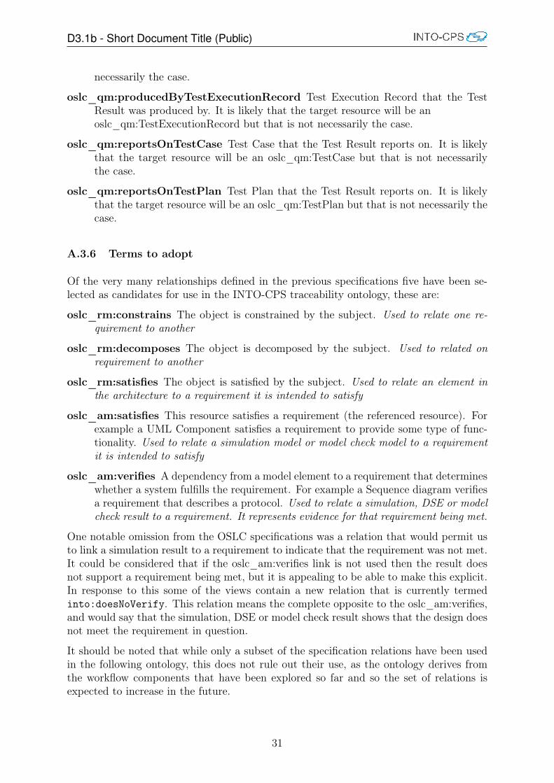
Figure 6: Block Definition Diagram (BDD) of the requirements activity
A.4 Proposed INTO-CPS Traceability Ontology
In subsection A.2 the concepts of PROV were introduced and in subsection A.3 we out-lined the pertinent OSLC specification with some discussion about which are likely usefulfor the INTO-CPS traceability work. In this subsection we will combine both the PROVand OSLC work to describe an ontology that will form the basis of the provenance andtraceability data in INTO-CPS.
The ontology is presented as a collection a views where the majority of the views arecentred around one or more activities that will take place while using the INTO-CPStool chain. As with the PROV figures earlier a blue element represent an activity, ayellow element represents an entity and an orange element represents an agent.
A.4.1 Requirements
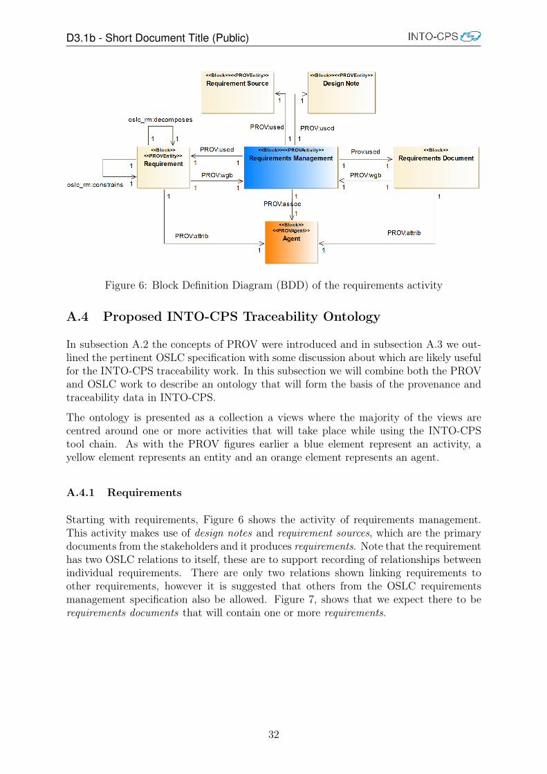
Starting with requirements, Figure 6 shows the activity of requirements management.This activity makes use of design notes and requirement sources, which are the primarydocuments from the stakeholders and it produces requirements. Note that the requirementhas two OSLC relations to itself, these are to support recording of relationships betweenindividual requirements. There are only two relations shown linking requirements toother requirements, however it is suggested that others from the OSLC requirementsmanagement specification also be allowed. Figure 7, shows that we expect there to berequirements documents that will contain one or more requirements.
32
D3.1b - Short Document Title (Public)
Figure 7: BDD of the requirements files
33
D3.1b - Short Document Title (Public)
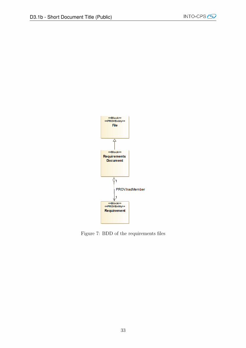
Figure 8: BDD Architecture modelling
A.4.2 Architecture Modelling
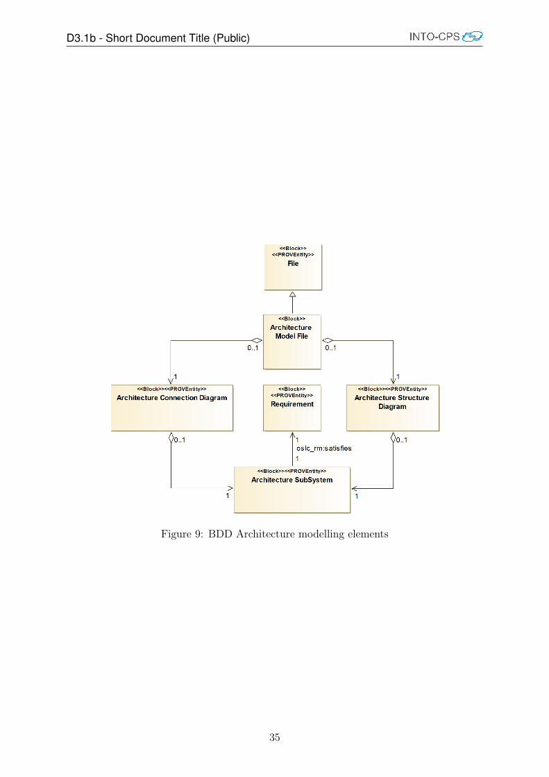
The activity of architecture modelling is presented in Figure 8. Architecture modellingis influenced by requirements, design notes and also previous version of its outputs, itproduces the two views defined in the INTO-CPS SysML profile (architecture structurediagram and architecture connection diagram, described in deliverable D2.1a [APCB15])and the architecture subsystems they contain. The architecture subsystems may be re-lated to any requirements they satisfy. The files that that represent the architecture areshown in Figure 9.
34
D3.1b - Short Document Title (Public)
Figure 9: BDD Architecture modelling elements
35
D3.1b - Short Document Title (Public)
Figure 10: BDD of the model description export activity
A.4.3 Model Description File Export
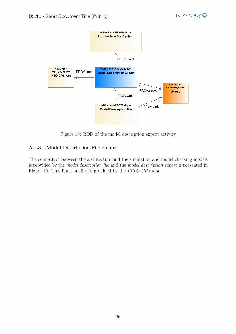
The connection between the architecture and the simulation and model checking modelsis provided by the model description file and the model description export is presented inFigure 10. This functionality is provided by the INTO-CPS app.
36
D3.1b - Short Document Title (Public)
Figure 11: BDD showing simulation model creation activities
A.4.4 Simulation Models
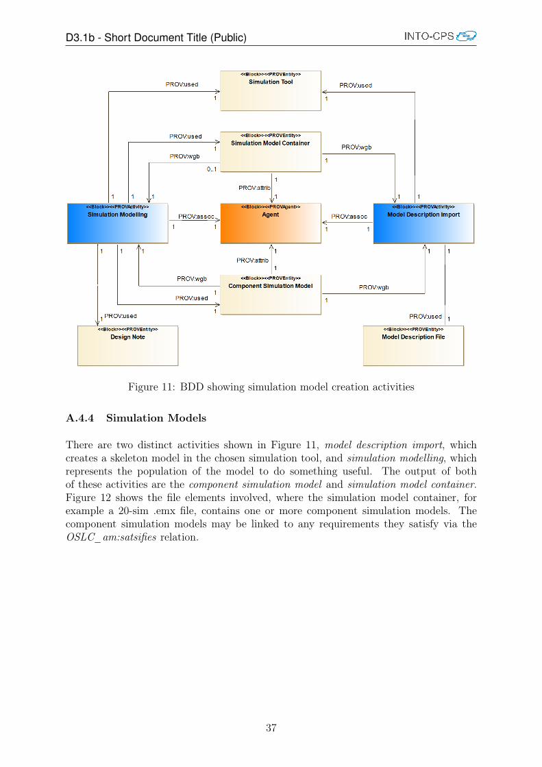
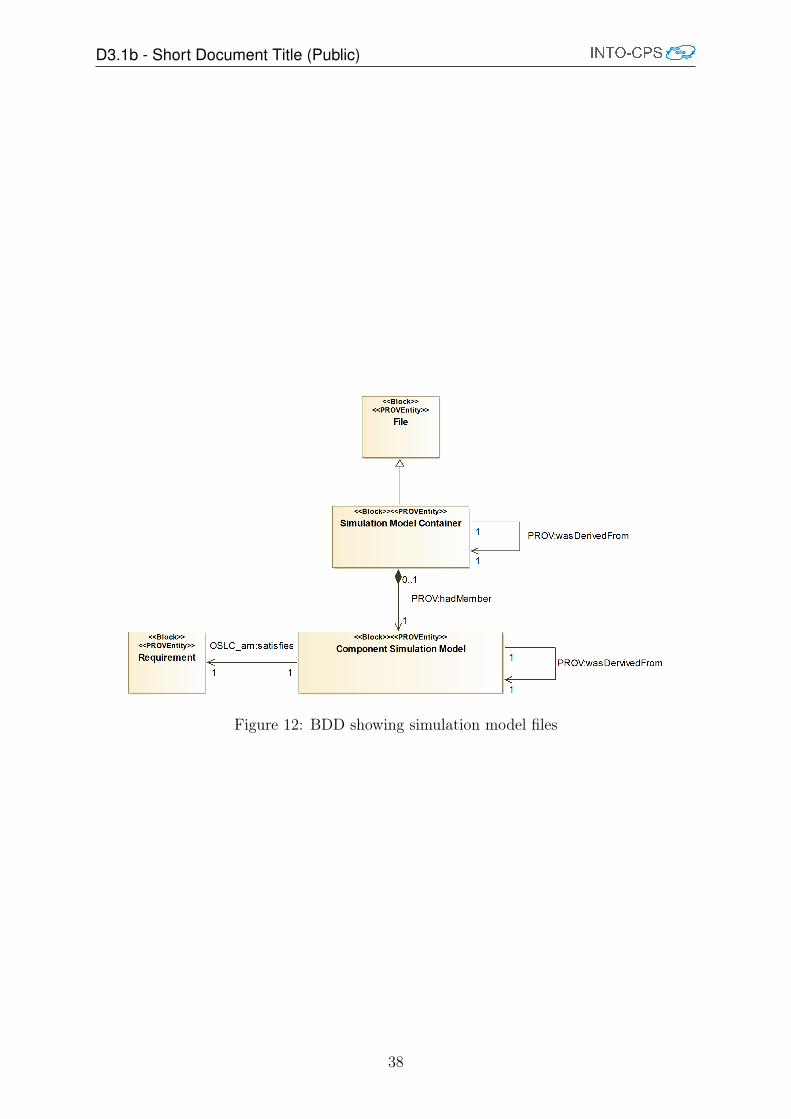
There are two distinct activities shown in Figure 11, model description import, whichcreates a skeleton model in the chosen simulation tool, and simulation modelling, whichrepresents the population of the model to do something useful. The output of bothof these activities are the component simulation model and simulation model container.Figure 12 shows the file elements involved, where the simulation model container, forexample a 20-sim .emx file, contains one or more component simulation models. Thecomponent simulation models may be linked to any requirements they satisfy via theOSLC_am:satsifies relation.
37
D3.1b - Short Document Title (Public)
Figure 12: BDD showing simulation model files
38
D3.1b - Short Document Title (Public)
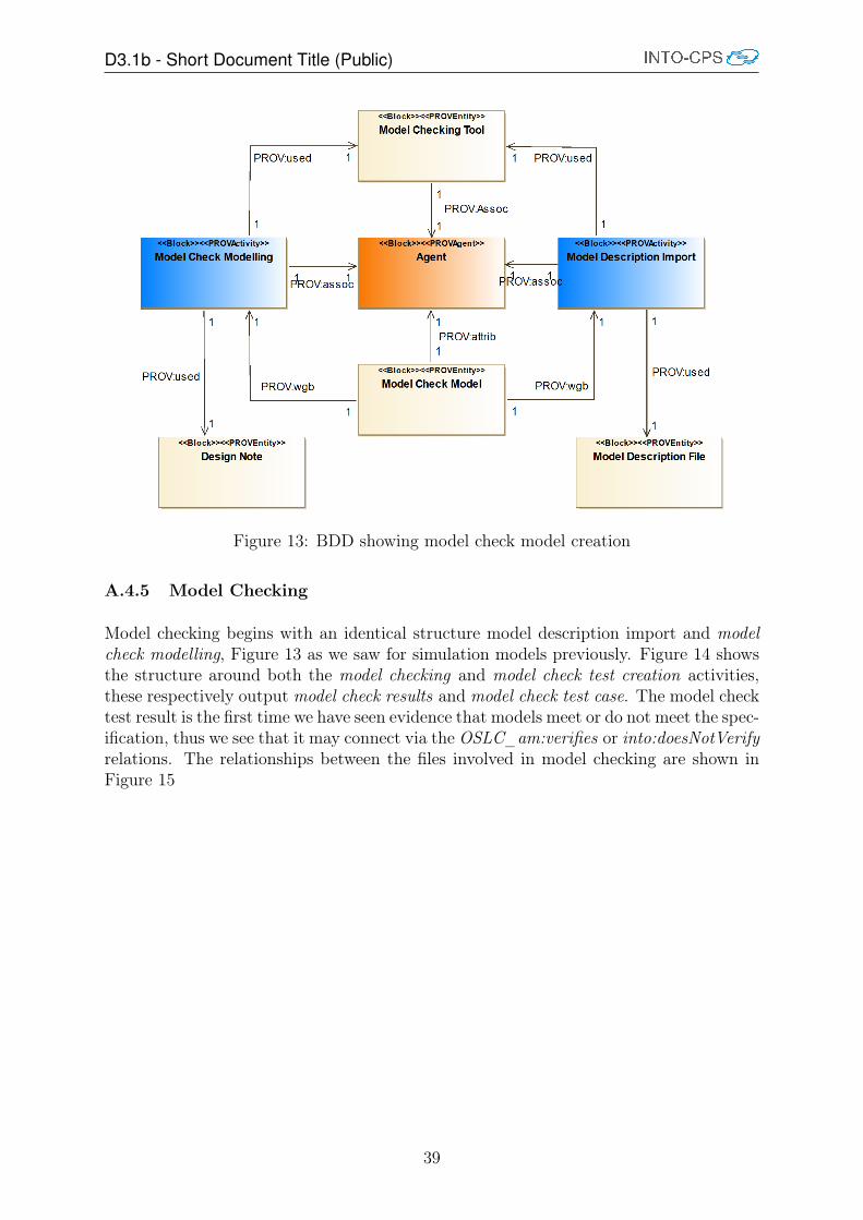
Figure 13: BDD showing model check model creation
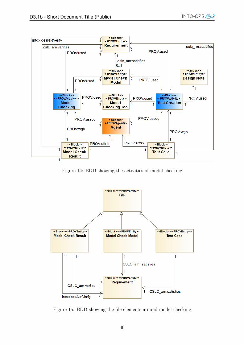
A.4.5 Model Checking
Model checking begins with an identical structure model description import and modelcheck modelling, Figure 13 as we saw for simulation models previously. Figure 14 showsthe structure around both the model checking and model check test creation activities,these respectively output model check results and model check test case. The model checktest result is the first time we have seen evidence that models meet or do not meet the spec-ification, thus we see that it may connect via the OSLC_am:verifies or into:doesNotVerifyrelations. The relationships between the files involved in model checking are shown inFigure 15
39
D3.1b - Short Document Title (Public)
Figure 14: BDD showing the activities of model checking
Figure 15: BDD showing the file elements around model checking
40
D3.1b - Short Document Title (Public)
Figure 16: BDD showing simulation FMU generation
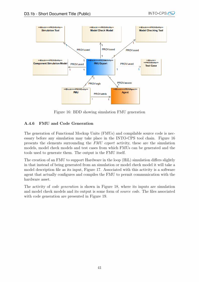
A.4.6 FMU and Code Generation
The generation of Functional Mockup Units (FMUs) and compilable source code is nec-essary before any simulation may take place in the INTO-CPS tool chain. Figure 16presents the elements surrounding the FMU export activity, these are the simulationmodels, model check models and test cases from which FMUs can be generated and thetools used to generate them. The output is the FMU itself.
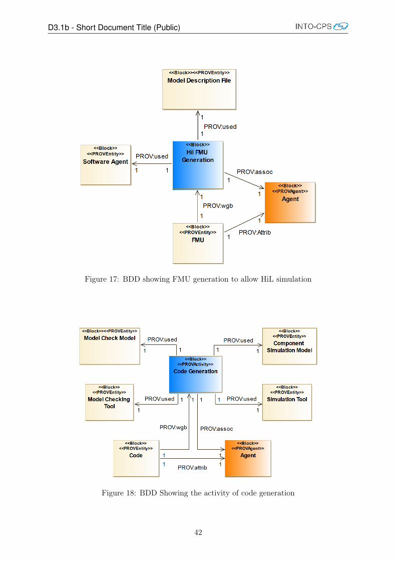
The creation of an FMU to support Hardware in the loop (HiL) simulation differs slightlyin that instead of being generated from an simulation or model check model it will take amodel description file as its input, Figure 17. Associated with this activity is a softwareagent that actually configures and compiles the FMU to permit communication with thehardware asset.
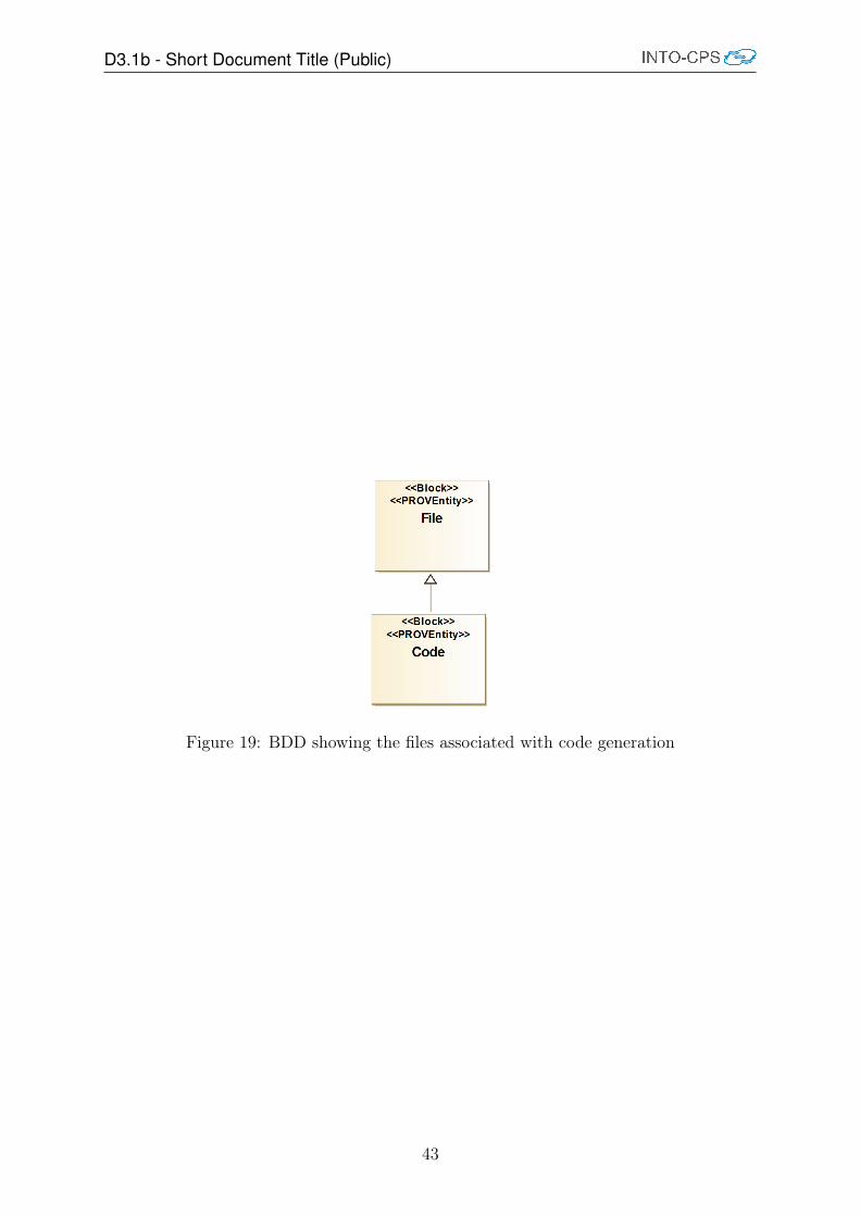
The activity of code generation is shown in Figure 18, where its inputs are simulationand model check models and its output is some form of source code. The files associatedwith code generation are presented in Figure 19.
41
D3.1b - Short Document Title (Public)
Figure 17: BDD showing FMU generation to allow HiL simulation
Figure 18: BDD Showing the activity of code generation
42
D3.1b - Short Document Title (Public)
Figure 19: BDD showing the files associated with code generation
43
D3.1b - Short Document Title (Public)
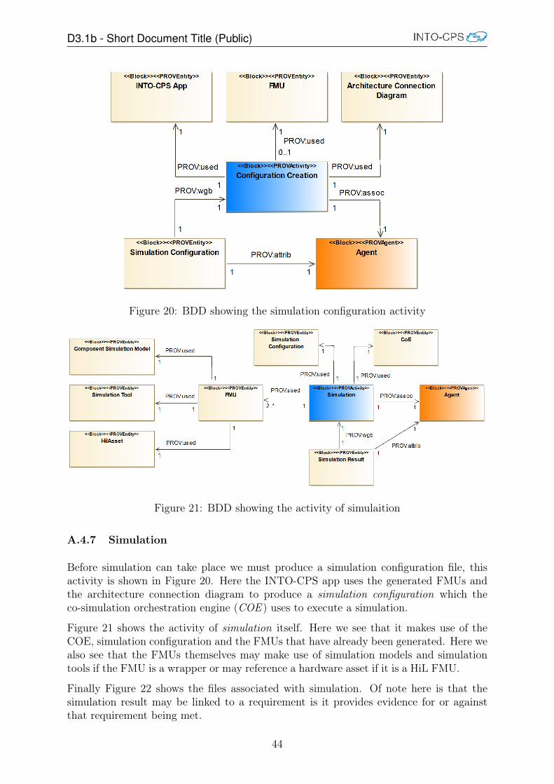
Figure 20: BDD showing the simulation configuration activity
Figure 21: BDD showing the activity of simulaition
A.4.7 Simulation
Before simulation can take place we must produce a simulation configuration file, thisactivity is shown in Figure 20. Here the INTO-CPS app uses the generated FMUs andthe architecture connection diagram to produce a simulation configuration which theco-simulation orchestration engine (COE ) uses to execute a simulation.
Figure 21 shows the activity of simulation itself. Here we see that it makes use of theCOE, simulation configuration and the FMUs that have already been generated. Here wealso see that the FMUs themselves may make use of simulation models and simulationtools if the FMU is a wrapper or may reference a hardware asset if it is a HiL FMU.
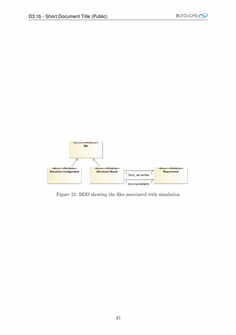
Finally Figure 22 shows the files associated with simulation. Of note here is that thesimulation result may be linked to a requirement is it provides evidence for or againstthat requirement being met.
44
D3.1b - Short Document Title (Public)
Figure 22: BDD showing the files associated with simulation
45
D3.1b - Short Document Title (Public)
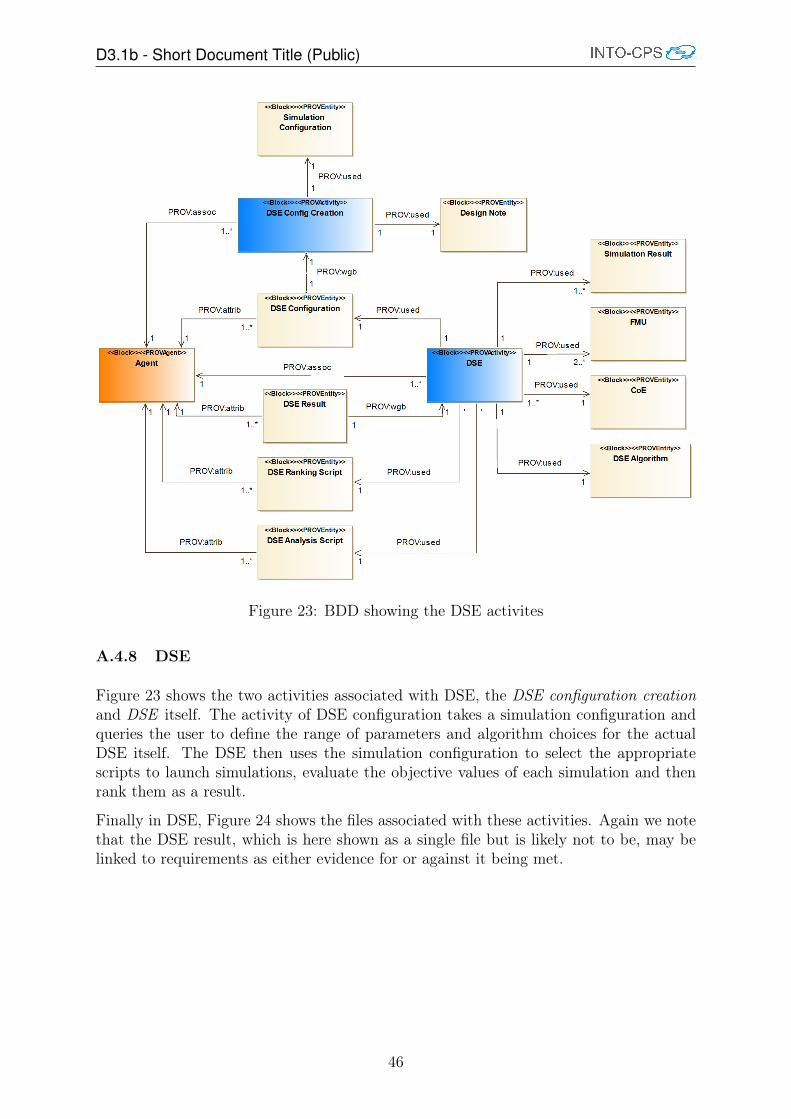
Figure 23: BDD showing the DSE activites
A.4.8 DSE
Figure 23 shows the two activities associated with DSE, the DSE configuration creationand DSE itself. The activity of DSE configuration takes a simulation configuration andqueries the user to define the range of parameters and algorithm choices for the actualDSE itself. The DSE then uses the simulation configuration to select the appropriatescripts to launch simulations, evaluate the objective values of each simulation and thenrank them as a result.
Finally in DSE, Figure 24 shows the files associated with these activities. Again we notethat the DSE result, which is here shown as a single file but is likely not to be, may belinked to requirements as either evidence for or against it being met.
46

D3.1b - Short Document Title (Public)
Figure 24: BDD showing the DSE files
47
D3.1b - Short Document Title (Public)
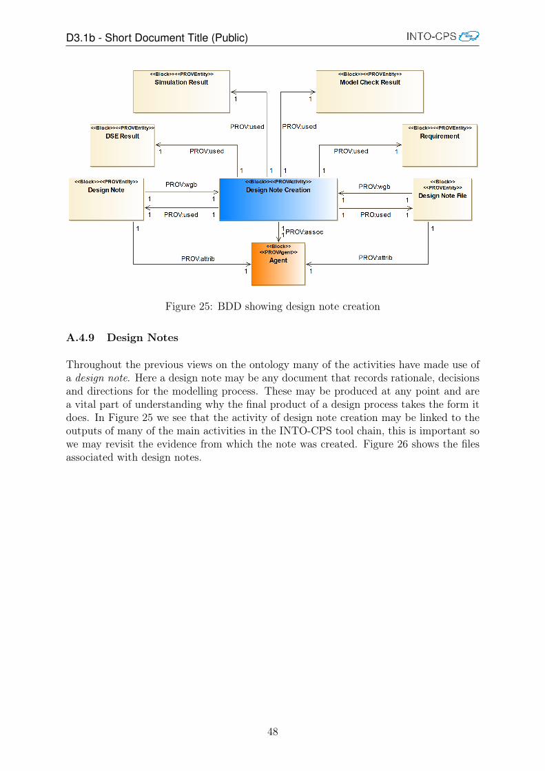
Figure 25: BDD showing design note creation
A.4.9 Design Notes
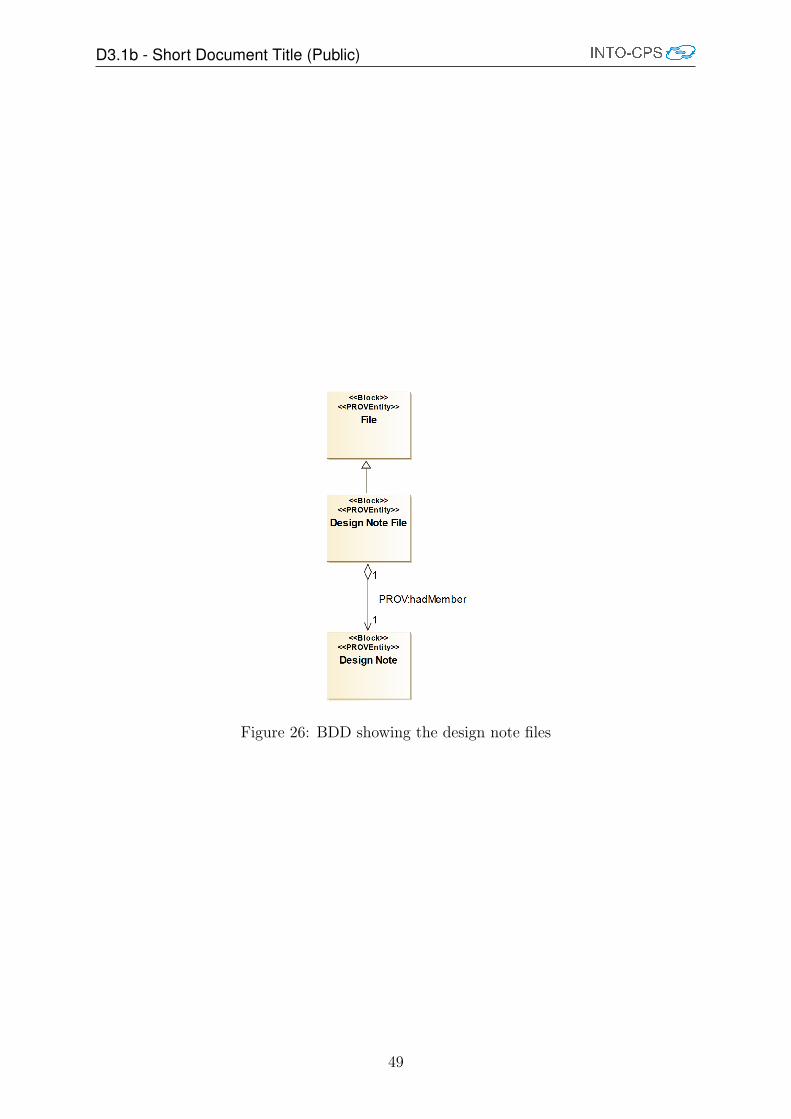
Throughout the previous views on the ontology many of the activities have made use ofa design note. Here a design note may be any document that records rationale, decisionsand directions for the modelling process. These may be produced at any point and area vital part of understanding why the final product of a design process takes the form itdoes. In Figure 25 we see that the activity of design note creation may be linked to theoutputs of many of the main activities in the INTO-CPS tool chain, this is important sowe may revisit the evidence from which the note was created. Figure 26 shows the filesassociated with design notes.
48
D3.1b - Short Document Title (Public)
Figure 26: BDD showing the design note files
49
D3.1b - Short Document Title (Public)
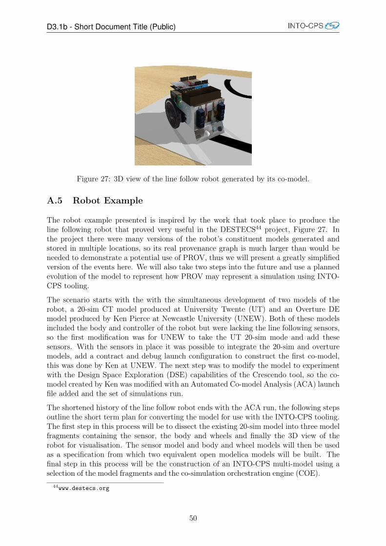
Figure 27: 3D view of the line follow robot generated by its co-model.
A.5 Robot Example
The robot example presented is inspired by the work that took place to produce theline following robot that proved very useful in the DESTECS44 project, Figure 27. Inthe project there were many versions of the robot’s constituent models generated andstored in multiple locations, so its real provenance graph is much larger than would beneeded to demonstrate a potential use of PROV, thus we will present a greatly simplifiedversion of the events here. We will also take two steps into the future and use a plannedevolution of the model to represent how PROV may represent a simulation using INTO-CPS tooling.
The scenario starts with the with the simultaneous development of two models of therobot, a 20-sim CT model produced at University Twente (UT) and an Overture DEmodel produced by Ken Pierce at Newcastle University (UNEW). Both of these modelsincluded the body and controller of the robot but were lacking the line following sensors,so the first modification was for UNEW to take the UT 20-sim mode and add thesesensors. With the sensors in place it was possible to integrate the 20-sim and overturemodels, add a contract and debug launch configuration to construct the first co-model,this was done by Ken at UNEW. The next step was to modify the model to experimentwith the Design Space Exploration (DSE) capabilities of the Crescendo tool, so the co-model created by Ken was modified with an Automated Co-model Analysis (ACA) launchfile added and the set of simulations run.
The shortened history of the line follow robot ends with the ACA run, the following stepsoutline the short term plan for converting the model for use with the INTO-CPS tooling.The first step in this process will be to dissect the existing 20-sim model into three modelfragments containing the sensor, the body and wheels and finally the 3D view of therobot for visualisation. The sensor model and body and wheel models will then be usedas a specification from which two equivalent open modelica models will be built. Thefinal step in this process will be the construction of an INTO-CPS multi-model using aselection of the model fragments and the co-simulation orchestration engine (COE).
44www.destecs.org
50
D3.1b - Short Document Title (Public)
In the following sub-subsections examples of how PROV could be used to record theevents will be shown.
A.5.1 Model Introduction
There are examples of two types of model introduction in the robot study. On the righthand side of Figure 28(a) we can see the introduction of the CT model developed byUT. This model was supplied in its final form by UT and so we only need to record theidentity of the entity (file) provided, the agent responsible for the entity and link themwith a ‘was attributed to’ relation. This pattern could be used to represent any modelthat is provided by an external agency, for example if a tyre supplier provided a vehiclemanufacturer with a compiled FMU for their tyre for use in simulations.
The structure on the left hand side of Figure 28(a) represents the internal developmentof new models. Here we record the identities of the model files produced, the name ofthe engineer responsible and the name and version of the tooling used. Central to theproduction of these models is the deModelling activity, apart from the id of activity theelement can be used to record the start and/or end times of the modelling activity. Theengineer, Ken, is associated with both the activity of modelling via a ‘was associatedwith’ relation and with the generated files via the ‘was attributed to’ relation. The filesare also linked to the activity via the ‘was generated by’ relation. Finally we indicatewhich tool was used by connecting deModelling to Overture via a “used” relation.
A.5.2 Model Evolution
The PROV structure used to represent a new model entity being created from an existingone is very similar to that used for model introduction but with the addition of further“used” entities defining the which model files were used a sources. Figure 29 showsthe evolution of the UT CT model to have line follow sensors. Note that utCT.emxis not only connected to the activity by the used relation but is also connected to theunewCT.emx entity via a was derived from relation. In this example there was only onesource model and one generated model and so there is no ambiguity regarding whichmodels influenced which other models, however this is not always the case. If we considerthe two modelling exercises shown in Figure 30 we see that ambiguity could be present.In the modelling2 activity, where the single 20-sim model is decomposed into smallercomponents, we can see that there is one source model and two generated models and wecan infer that the two generated models were both influenced in some way by the singlesource model. However, in the modelling3 activity, in which openModelica versions ofthe 20-sim component models are produced, there are two source models and two outputmodels. Here the derived relation helps to make explicit which of the produced modelswas influenced by which of the source models. This explicit lineage could be importantif there is a need to trace some property through the model chain.
A.5.3 Simulation
Figure 31 shows the PROV structure for the initial DE only simulation performed atUNEW. Here we list the input modes, the activity of simulation, the agent responsible
51
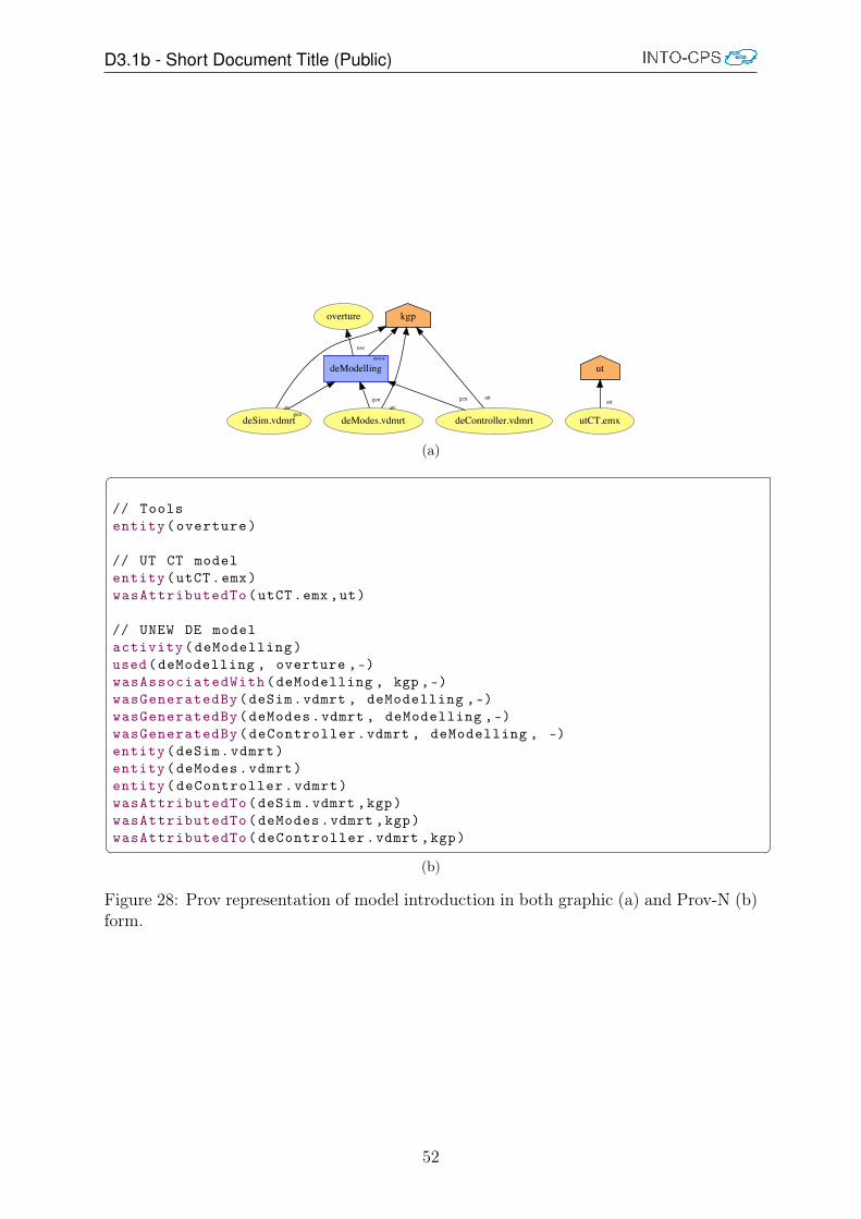
D3.1b - Short Document Title (Public)
deModelling
overture
use
kgp
assoc
utCT.emx
ut
att
deSim.vdmrtgen
att
deModes.vdmrt
gen
att
deController.vdmrt
gen att
(a)�// Toolsentity(overture)
// UT CT modelentity(utCT.emx)wasAttributedTo(utCT.emx ,ut)
// UNEW DE modelactivity(deModelling)used(deModelling , overture ,-)wasAssociatedWith(deModelling , kgp ,-)wasGeneratedBy(deSim.vdmrt , deModelling ,-)wasGeneratedBy(deModes.vdmrt , deModelling ,-)wasGeneratedBy(deController.vdmrt , deModelling , -)entity(deSim.vdmrt)entity(deModes.vdmrt)entity(deController.vdmrt)wasAttributedTo(deSim.vdmrt ,kgp)wasAttributedTo(deModes.vdmrt ,kgp)wasAttributedTo(deController.vdmrt ,kgp)� �
(b)
Figure 28: Prov representation of model introduction in both graphic (a) and Prov-N (b)form.
52

D3.1b - Short Document Title (Public)
modelling1
20-sim4.3
use
utCT.emx
use
cjg
assoc
unewCT.emx
gender
att
(a)�// Toolsentity (20-sim4 .3)
// UT CT modelentity(utCT.emx)
// UNEW CT Sensors added and testedentity(unewCT.emx)wasAttributedTo(unewCT.emx ,cjg)activity(modelling1)used(modelling1 , 20-sim4.3,-)wasGeneratedBy(unewCT.emx , modelling1 ,-)wasAssociatedWith(modelling1 , cjg ,-)used(modelling1 ,utCT.emx ,-)wasDerivedFrom(unewCT.emx ,utCT.emx)� �
(b)
Figure 29: Prov representation of simple model evolution in both graphic (a) and Prov-N(b) form.
53

D3.1b - Short Document Title (Public)
modelling2
unewCT.emx
use
modelling3
ctBody.emx
use
ctSensor.emx
use
gender
gender
ct3D.emx
gen der
ctBody.mogen
der
ctSensor.mo
gender
(a)�entity(unewCT.emx)
// creation of ct model fragments (20-sim)activity(modelling2)used(modelling2 , unewCT.emx , -)entity(ctBody.emx)entity(ctSensor.emx)entity(ct3D.emx)wasGeneratedBy(ctBody.emx , modelling2 , -)wasGeneratedBy(ctSensor.emx , modelling2 , -)wasGeneratedBy(ct3D.emx , modelling2 , -)wasDerivedFrom(ctBody.emx , unewCT.emx)wasDerivedFrom(ctSensor.emx , unewCT.emx)wasDerivedFrom(ct3D.emx , unewCT.emx)
// creation of ct model fragments (open modelica)activity(modelling3)used(modelling3 , ctSensor.emx , -)used(modelling3 , ctBody.emx , -)entity(ctBody.mo)entity(ctSensor.mo)wasGeneratedBy(ctBody.mo, modelling3 , -)wasGeneratedBy(ctSensor.mo, modelling3 , -)wasDerivedFrom(ctBody.mo, ctBody.emx)wasDerivedFrom(ctSensor.mo, ctSensor.emx)� �
(b)
Figure 30: Prov represel evolution in both graphic (a) and Prov-N (b) form.
54
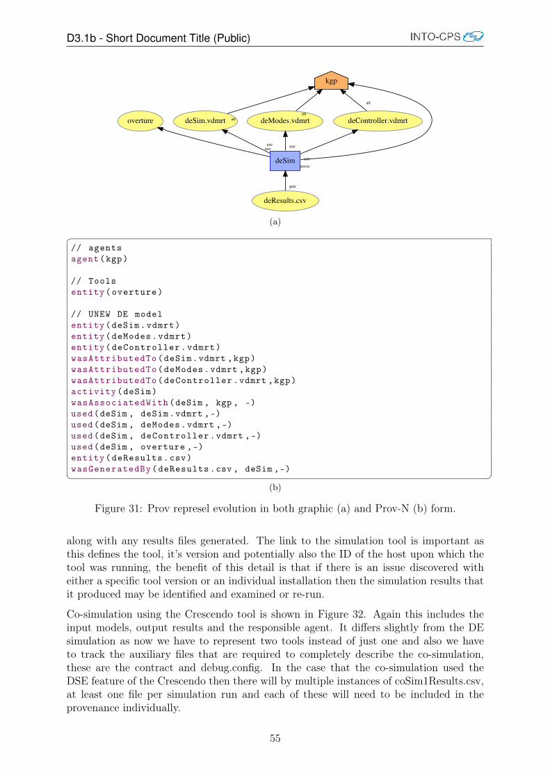
D3.1b - Short Document Title (Public)
deSim
overture
use
deSim.vdmrt
use
deModes.vdmrt
use
deController.vdmrt
use
kgp
assoc
attatt
att
deResults.csv
gen
(a)�// agentsagent(kgp)
// Toolsentity(overture)
// UNEW DE modelentity(deSim.vdmrt)entity(deModes.vdmrt)entity(deController.vdmrt)wasAttributedTo(deSim.vdmrt ,kgp)wasAttributedTo(deModes.vdmrt ,kgp)wasAttributedTo(deController.vdmrt ,kgp)activity(deSim)wasAssociatedWith(deSim , kgp , -)used(deSim , deSim.vdmrt ,-)used(deSim , deModes.vdmrt ,-)used(deSim , deController.vdmrt ,-)used(deSim , overture ,-)entity(deResults.csv)wasGeneratedBy(deResults.csv , deSim ,-)� �
(b)
Figure 31: Prov represel evolution in both graphic (a) and Prov-N (b) form.
along with any results files generated. The link to the simulation tool is important asthis defines the tool, it’s version and potentially also the ID of the host upon which thetool was running, the benefit of this detail is that if there is an issue discovered witheither a specific tool version or an individual installation then the simulation results thatit produced may be identified and examined or re-run.
Co-simulation using the Crescendo tool is shown in Figure 32. Again this includes theinput models, output results and the responsible agent. It differs slightly from the DEsimulation as now we have to represent two tools instead of just one and also we haveto track the auxiliary files that are required to completely describe the co-simulation,these are the contract and debug.config. In the case that the co-simulation used theDSE feature of the Crescendo then there will by multiple instances of coSim1Results.csv,at least one file per simulation run and each of these will need to be included in theprovenance individually.
55
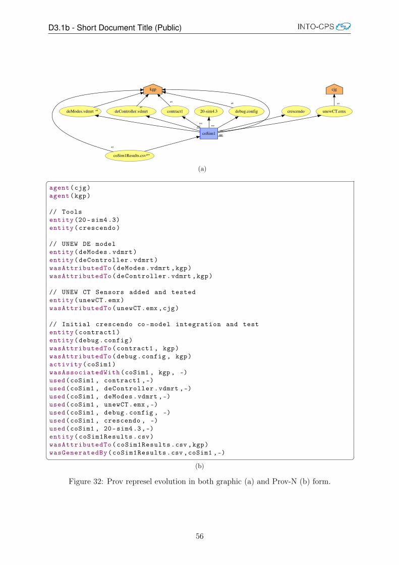
D3.1b - Short Document Title (Public)
coSim1
20-sim4.3
use
crescendo
use
deModes.vdmrt
use
deController.vdmrt
use
unewCT.emx
use
contract1
use
debug.config
use
kgp
assoc
att
att
cjg
attatt
att
coSim1Results.csvgen
att
(a)�agent(cjg)agent(kgp)
// Toolsentity (20-sim4 .3)entity(crescendo)
// UNEW DE modelentity(deModes.vdmrt)entity(deController.vdmrt)wasAttributedTo(deModes.vdmrt ,kgp)wasAttributedTo(deController.vdmrt ,kgp)
// UNEW CT Sensors added and testedentity(unewCT.emx)wasAttributedTo(unewCT.emx ,cjg)
// Initial crescendo co-model integration and testentity(contract1)entity(debug.config)wasAttributedTo(contract1 , kgp)wasAttributedTo(debug.config , kgp)activity(coSim1)wasAssociatedWith(coSim1 , kgp , -)used(coSim1 , contract1 ,-)used(coSim1 , deController.vdmrt ,-)used(coSim1 , deModes.vdmrt ,-)used(coSim1 , unewCT.emx ,-)used(coSim1 , debug.config , -)used(coSim1 , crescendo , -)used(coSim1 , 20-sim4.3,-)entity(coSim1Results.csv)wasAttributedTo(coSim1Results.csv ,kgp)wasGeneratedBy(coSim1Results.csv ,coSim1 ,-)� �
(b)
Figure 32: Prov represel evolution in both graphic (a) and Prov-N (b) form.
56

D3.1b - Short Document Title (Public)
For the INTO-CPS style of co-simulation we need to use a slightly different structureto properly represent the configuration of the co-model and to allow replay, such anenvisaged structure is show in Figure 33. This structure still contains the main elementsof the previous simulations, the input models, tools, agents and auxillary files, but thereis now an additional layer of activities between the input models and the co-simulationactivity. For example, ctBody.emx is used by sim1 and coSim2 is informed by sim1,similarly ct3D.emx is used by sim2 and coSim2 is informed by sim2. The reason behindthis structure is that we may choose to have multiple simulations that use the same toolfamily, e.g. 20-sim, but due to the distributed nature of the COE could be executed ondifferent instances the tool, or different versions on different hosts. So in the figure weuse simX to allow use to be more explicit about which models were running on whichtools, where the tools can also specify the host and version. This structure also closelymimics the structure of an INTO-CPS co-simulation, with each simX representing oneFMU and the informed relations representing the data shared over the FMI bus.
57
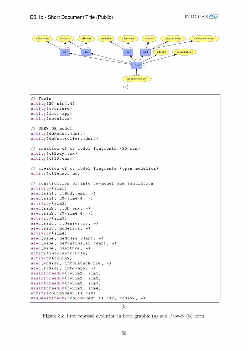
D3.1b - Short Document Title (Public)
sim1
20-sim4.4
use
ctBody.emx
use
sim2
use
ct3D.emx
use
sim3
modelica
use
ctSensor.mo
use
sim4
overture
use
deModes.vdmrt
use
deController.vdmrt
use
coSim2
infinfinf
inf
into-app
use
intoLaunchFile
use
coSim2Results.csv
gen
(a)�// Toolsentity (20-sim4 .4)entity(overture)entity(into -app)entity(modelica)
// UNEW DE modelentity(deModes.vdmrt)entity(deController.vdmrt)
// creation of ct model fragments (20-sim)entity(ctBody.emx)entity(ct3D.emx)
// creation of ct model fragments (open modelica)entity(ctSensor.mo)
// construction of into co -model and simulationactivity(sim1)used(sim1 , ctBody.emx , -)used(sim1 , 20-sim4.4, -)activity(sim2)used(sim2 , ct3D.emx , -)used(sim2 , 20-sim4.4, -)activity(sim3)used(sim3 , ctSensor.mo, -)used(sim3 , modelica , -)activity(sim4)used(sim4 , deModes.vdmrt , -)used(sim4 , deController.vdmrt , -)used(sim4 , overture , -)entity(intoLaunchFile)activity(coSim2)used(coSim2 , intoLaunchFile , -)used(coSim2 , into -app , -)wasInformedBy(coSim2 , sim1)wasInformedBy(coSim2 , sim2)wasInformedBy(coSim2 , sim3)wasInformedBy(coSim2 , sim4)entity(coSim2Results.csv)wasGeneratedBy(coSim2Results.csv , coSim2 , -)� �
(b)
Figure 33: Prov represel evolution in both graphic (a) and Prov-N (b) form.
58
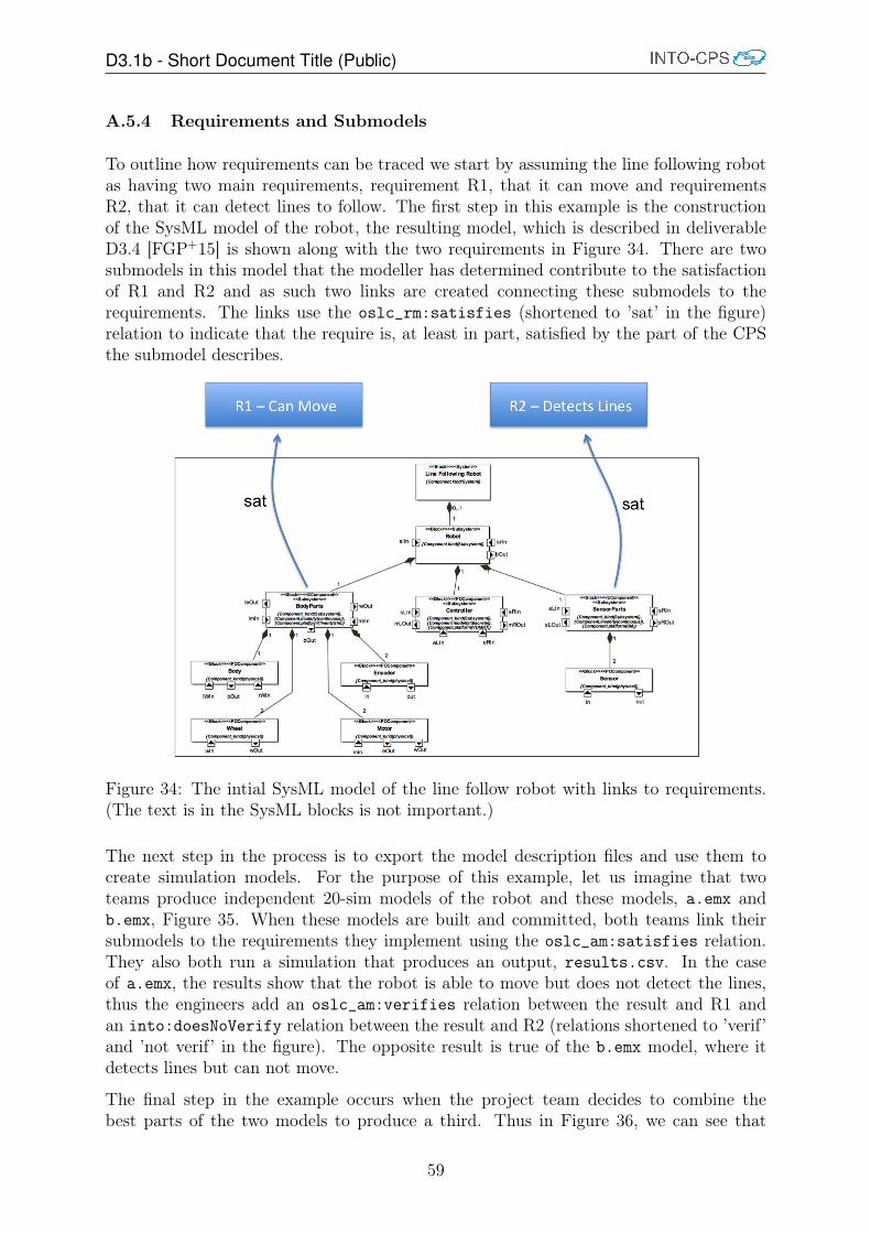
D3.1b - Short Document Title (Public)
A.5.4 Requirements and Submodels
To outline how requirements can be traced we start by assuming the line following robotas having two main requirements, requirement R1, that it can move and requirementsR2, that it can detect lines to follow. The first step in this example is the constructionof the SysML model of the robot, the resulting model, which is described in deliverableD3.4 [FGP+15] is shown along with the two requirements in Figure 34. There are twosubmodels in this model that the modeller has determined contribute to the satisfactionof R1 and R2 and as such two links are created connecting these submodels to therequirements. The links use the oslc_rm:satisfies (shortened to ’sat’ in the figure)relation to indicate that the require is, at least in part, satisfied by the part of the CPSthe submodel describes.
Figure 34: The intial SysML model of the line follow robot with links to requirements.(The text is in the SysML blocks is not important.)
The next step in the process is to export the model description files and use them tocreate simulation models. For the purpose of this example, let us imagine that twoteams produce independent 20-sim models of the robot and these models, a.emx andb.emx, Figure 35. When these models are built and committed, both teams link theirsubmodels to the requirements they implement using the oslc_am:satisfies relation.They also both run a simulation that produces an output, results.csv. In the caseof a.emx, the results show that the robot is able to move but does not detect the lines,thus the engineers add an oslc_am:verifies relation between the result and R1 andan into:doesNoVerify relation between the result and R2 (relations shortened to ’verif’and ’not verif’ in the figure). The opposite result is true of the b.emx model, where itdetects lines but can not move.
The final step in the example occurs when the project team decides to combine thebest parts of the two models to produce a third. Thus in Figure 36, we can see that
59
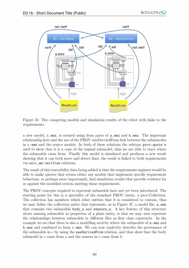
D3.1b - Short Document Title (Public)
Figure 35: Two competing models and simulation results of the robot with links to therequirements.
a new model, c.emx, is created using from parts of a.emx and b.emx. The importantrelationship here and the use of the PROV wasDerviedFrom link between the submmodesin c.emx and the source models. In both of these relations the subtype prov:quote isused to show that it is a copy of the orginal submodel, thus we are able to trace wherethe submodels came from. Finally this model is simulated and produces a new resultshowing that it can both move and detect lines, the result is linked to both requirementsvia oslc_am:verifies relations.
The result of this traceability data being added is that the requirements engineer would beable to make queries that return either any models that implement specific requirementbehaviour, or perhaps more importantly, find simulation results that provide evidence foror against the modelled system meeting those requirements.
The PROV concepts required to represent submodels have not yet been introduced. Thestarting point for this is a speciality of the standard PROV entity, a prov:Collection.The collection has members which other entities that it is considered to contain, thuswe may define the collection entity that represents, as in Figure 37, a model file, a.emxthat contains two submodels body_a and sensors_a. A key feature of this structureabove naming submodels as properties of a plain entity, is that we may now representthe relationships between submodels in different files as first class constructs. In theexample we see that there is also a modelling activity where the submodels of a.emx andb.emx and combined to form c.emx. We can now explicitly describe the provenance ofthe submodels in c by using the wasDerivedFrom relation, and thus show that the bodysubmodel in c came from a and the sensors in c came from b.
60

D3.1b - Short Document Title (Public)
Figure 36: A final model of the robot that meets both requirements
61
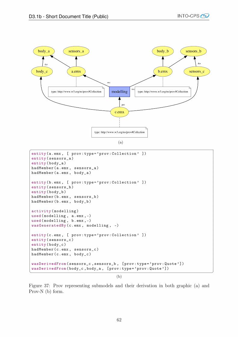
D3.1b - Short Document Title (Public)
(a)�entity(a.emx , [ prov:type=’prov:Collection ’ ])entity(sensors_a)entity(body_a)hadMember(a.emx , sensors_a)hadMember(a.emx , body_a)
entity(b.emx , [ prov:type=’prov:Collection ’ ])entity(sensors_b)entity(body_b)hadMember(b.emx , sensors_b)hadMember(b.emx , body_b)
activity(modelling)used(modelling , a.emx ,-)used(modelling , b.emx ,-)wasGeneratedBy(c.emx , modelling , -)
entity(c.emx , [ prov:type=’prov:Collection ’ ])entity(sensors_c)entity(body_c)hadMember(c.emx , sensors_c)hadMember(c.emx , body_c)
wasDerivedFrom(sensors_c ,sensors_b , [prov:type=’prov:Quote’])wasDerivedFrom(body_c ,body_a , [prov:type=’prov:Quote ’])� �
(b)
Figure 37: Prov representing submodels and their derivation in both graphic (a) andProv-N (b) form.
62
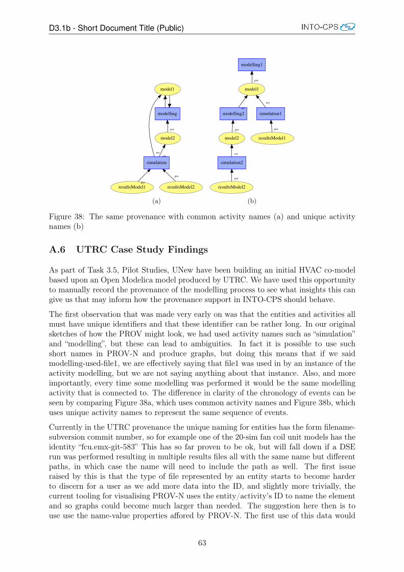
D3.1b - Short Document Title (Public)
modelling
model1
use
simulation
use
model2
use
gen
gen
resultsModel1gen
resultsModel2
gen
(a)
modelling1
modelling2
model1
use
simulation1
use
simulation2
model2
use
gen
gen
resultsModel1
gen
resultsModel2
gen
(b)
Figure 38: The same provenance with common activity names (a) and unique activitynames (b)
A.6 UTRC Case Study Findings
As part of Task 3.5, Pilot Studies, UNew have been building an initial HVAC co-modelbased upon an Open Modelica model produced by UTRC. We have used this opportunityto manually record the provenance of the modelling process to see what insights this cangive us that may inform how the provenance support in INTO-CPS should behave.
The first observation that was made very early on was that the entities and activities allmust have unique identifiers and that these identifier can be rather long. In our originalsketches of how the PROV might look, we had used activity names such as “simulation”and “modelling”, but these can lead to ambiguities. In fact it is possible to use suchshort names in PROV-N and produce graphs, but doing this means that if we saidmodelling-used-file1, we are effectively saying that file1 was used in by an instance of theactivity modelling, but we are not saying anything about that instance. Also, and moreimportantly, every time some modelling was performed it would be the same modellingactivity that is connected to. The difference in clarity of the chronology of events can beseen by comparing Figure 38a, which uses common activity names and Figure 38b, whichuses unique activity names to represent the same sequence of events.
Currently in the UTRC provenance the unique naming for entities has the form filename-subversion commit number, so for example one of the 20-sim fan coil unit models has theidentity “fcu.emx-git-583” This has so far proven to be ok, but will fall down if a DSErun was performed resulting in multiple results files all with the same name but differentpaths, in which case the name will need to include the path as well. The first issueraised by this is that the type of file represented by an entity starts to become harderto discern for a user as we add more data into the ID, and slightly more trivially, thecurrent tooling for visualising PROV-N uses the entity/activity’s ID to name the elementand so graphs could become much larger than needed. The suggestion here then is touse use the name-value properties affored by PROV-N. The first use of this data would
63
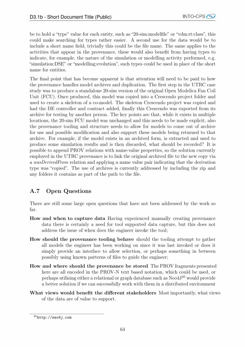
D3.1b - Short Document Title (Public)
be to hold a “type” value for each entity, such as “20-sim:modelfile” or “vdm:rt:class”, thiscould make searching for types rather easier. A second use for the data would be toinclude a short name field, trivially this could be the file name. The same applies to theactivities that appear in the provenance, these would also benefit from having types toindicate, for example, the nature of the simulation or modelling activity performed, e.g.“simulation:DSE” or “modelling:evolution”, such types could be used in place of the shortname for entities.
The final point that has become apparent is that attention will need to be paid to howthe provenance handles model archives and duplication. The first step in the UTRC casestudy was to produce a standalone 20-sim version of the original Open Modelica Fan CoilUnit (FCU). Once produced, this model was copied into a Crescendo project folder andused to create a skeleton of a co-model. The skeleton Crescendo project was copied andhad the DE controller and contract added, finally this Crescendo was exported from itsarchive for testing by another person. The key points are that, while it exists in multiplelocations, the 20-sim FCU model was unchanged and this needs to be made explicit, alsothe provenance tooling and structure needs to allow for models to come out of archivefor use and possible modification and also support these models being returned to thatarchive. For example, if the model exists in an archived form, is extracted and used toproduce some simulation results and is then discarded, what should be recorded? It ispossible to append PROV relations with name-value properties, so the solution currentlyemployed in the UTRC provenance is to link the original archived file to the new copy viaa wasDerivedFrom relation and applying a name value pair indicating that the derivationtype was “copied”. The use of archives is currently addressed by including the zip andany folders it contains as part of the path to the file.
A.7 Open Questions
There are still some large open questions that have not been addressed by the work sofar.
How and when to capture data Having experienced manually creating provenancedata there is certainly a need for tool supported data capture, but this does notaddress the issue of when does the engineer invoke the tool;
How should the provenance tooling behave should the tooling attempt to gatherall models the engineer has been working on since it was last invoked or does itsimply provide an interface to allow selection, or perhaps something in betweenpossibly using known patterns of files to guide the engineer;
How and where should the provenance be stored The PROV fragments presentedhere are all encoded in the PROV-N text based notation, which could be used, orperhaps utilising either a relational or graph database such as Neo4J45 would providea better solution if we can successfully work with them in a distributed environment
What views would benefit the different stakeholders Most importantly, what viewsof the data are of value to support.
45http://neo4j.com
64