Methodology including all enclosures(modified 18-5-10)
39
BHASMEY HYDRO-ELECTRIC PROJECT, 2X27 MW SUBMISSION OF METHOD STATEMENT FOR CIVIL WORKS. SIMPLEX INFRASTRUCTURES LIMITED
-
Upload
gautam-sharma -
Category
Documents
-
view
66 -
download
0
Transcript of Methodology including all enclosures(modified 18-5-10)

BHASMEY HYDRO-ELECTRIC PROJECT, 2X27 MW SUBMISSION OF METHOD STATEMENT FOR CIVIL WORKS.
SIMPLEX INFRASTRUCTURES LIMITED
Page 2 of 39
INDEX
1. Head Race Tunnel
I. Adit 1, 2 & 3
II. H R T
III. HRT Lining
2. Surge Shaft
I. Open Excavation
II. Shaft Excavation
a. Pilot Shaft
b. Widening (upto 5.5m)
c. 2nd Stage Widening
d. 3rd Stage Widening
III. Rock Support IV. Lining
3. Butterfly Valve House
I. Adit
II. Valve House Chamber
a. Stage – 1
b. Stage – II
c. Stage – III
d. Stage – IV
e. Rock support f. Concreting
4. Pressure Shaft
I Rock Support Installation during Excavation
II Shotcrete
III Lining IV Grouting
5. River Diversion
I. Stage – 1 Cofferdam
II. Stage – 2 Cofferdam
III. Dam river Bed excavation & Care of Water
IV. Foundation Excavation
V. River bed excavation
VI. Soft material excavation
VII. Rock Excavation
VIII. Shotcrete
6. Intake
7. Power House
I. Main Equipments
8. Crusher Plant
I. Main Equipments.

Page 3 of 39
1. HEAD RACE TUNNEL
I. ADIT – 1, 2, 3
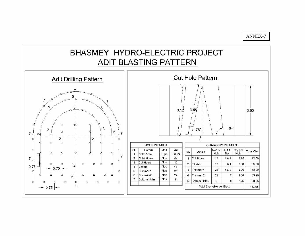
The excavation of head race tunnel will be taken up from Adit – 1, Adit – 2 and Adit – 3.The open Excavation of Adit – 1, 2 and 3 shall be executed with preparation of berms and stabilizing the slope with rock bolting/rock anchoring, shotcreting and drainage holes etc as per drawing and specification. We immediately during mobilization start, the open excavation to form portal of all Adits and after reaching the junction we will start excavation of d/s and u/s of head race tunnel. Initially jack hammers will be used for drilling of open excavation. Mucking will be done by Ex 100 or equivalent excavator with dumper/tippers. Subsequently two boom Drill Jumbo, and ROC 203 or equivalent m/c will be used for drilling. Drilling pattern and cycle proposed for HRT below will generally be used for Adit Excavation.
II. HRT
A head race tunnel 5.00 m finished diameter and 4585m long shall be taken up from Adit – 1, 2, 3. Tunnel will be excavated full face. Two boom hydraulic Drilling Jumbo will be used for drilling. EX 100 or equivalent Excavator for loading muck shall be mobilized with dumpers capacity 10 ton to 18 ton depending on the site condition. An effective progress of 75m/month is envisaged with different pull in different class of rock. Conventional support system like rock bolting, shotcrete with wire mess will be done during every cycle time of advancement. Under adverse geological conditions where continuous rock fall is observed, steel rib supports with back fill concreting is the recommended rock support system. In flowing rock condition with heavy seepage, forepolling umbrella will be made. Cycle time and equipment planning for tunnel excavation are given hereunder. We would like to mention that we will provide niche (5mx5mx5m) @ 250m into main HRT to reduce transporting time of mucking.
Sl. No.
Description Unit Class-I & II Class- III Class- IV & V
Full Section
A Quantity % 30 30 40
1 Minimum Excavation sqm 26.84 26.84 28.78
2 Pay line sqm - - -
3 Pull m 3.25 2.75 1
4 Mucking quantity (solid) cum 87.23 87.23 28.78
5 Ditto (loose) + 60 % cum 139.57 139.57 46.05
6 Ditto Tonne at 1.75 T/cum MT 244.25 244.25 80.59
7 Loads (10 T) Nos. 25 25 9
B Drilling
1 No. of holes Nos. 85 85 85
2 Depth of holes M 3.75 3 1.5
3 Total drilling M 318.75 255 127.5
4 Drilling speed (Boomer) 150m/Hr Hr 2.13 1.7 0.85
Page 4 of 39
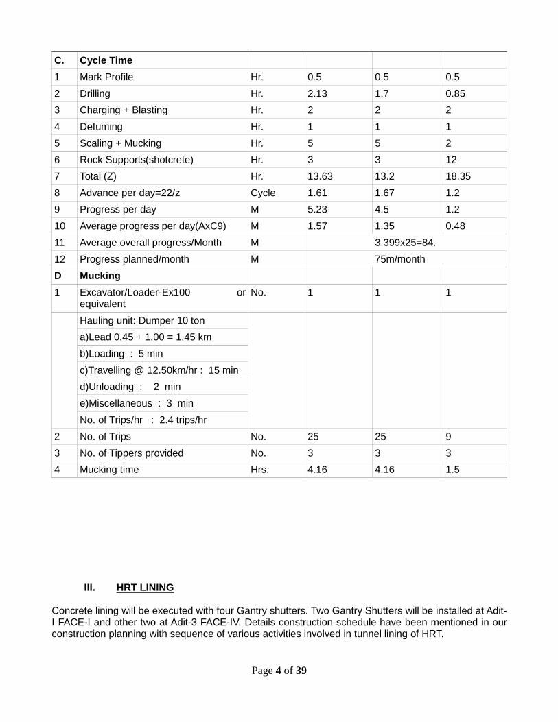
C. Cycle Time
1 Mark Profile Hr. 0.5 0.5 0.5
2 Drilling Hr. 2.13 1.7 0.85
3 Charging + Blasting Hr. 2 2 2
4 Defuming Hr. 1 1 1
5 Scaling + Mucking Hr. 5 5 2
6 Rock Supports(shotcrete) Hr. 3 3 12
7 Total (Z) Hr. 13.63 13.2 18.35
8 Advance per day=22/z Cycle 1.61 1.67 1.2
9 Progress per day M 5.23 4.5 1.2
10 Average progress per day(AxC9) M 1.57 1.35 0.48
11 Average overall progress/Month M 3.399x25=84.
12 Progress planned/month M 75m/month
D Mucking
1 Excavator/Loader-Ex100 or equivalent
No. 1 1 1
Hauling unit: Dumper 10 ton
a)Lead 0.45 + 1.00 = 1.45 km
b)Loading : 5 min
c)Travelling @ 12.50km/hr : 15 min
d)Unloading : 2 min
e)Miscellaneous : 3 min
No. of Trips/hr : 2.4 trips/hr
2 No. of Trips No. 25 25 9
3 No. of Tippers provided No. 3 3 3
4 Mucking time Hrs. 4.16 4.16 1.5
III. HRT LINING Concrete lining will be executed with four Gantry shutters. Two Gantry Shutters will be installed at Adit-I FACE-I and other two at Adit-3 FACE-IV. Details construction schedule have been mentioned in our construction planning with sequence of various activities involved in tunnel lining of HRT.

Page 5 of 39
Concrete Cycle Time A. For Invert Average Quantity of Concrete = 2.83 cum/RM of tunnel
I) We consider 20 m/day so qty. of concrete/day=57 cum concrete pouring time @ 15 cum/hr. = 3.8 hrs. ≈ 4 hrs.
II) Setting time = 10 hrs. III) Track laying and shifting of shutter = 3 hrs. IV) Alignment and setting = 4 hrs. V) Pump & pipe line shifting and fixing = 3 hrs.
Total = 24 hrs. So Cycle time matching our rate of progress and 30 cum/hrs batching plant one no. is sufficient for concreting as planned in our programmed. B) For overt Av concrete qty of concrete = 5.67cum/m i) We consider 10m/day, so qty = 3.78 hrs ≈ 4 hrs of concrete /day = 56.7 cum/day Therefore, concrete pouring time @ 15cum/hrs ii) Setting time =10 hrs iii) Collapsing of gantry, track laying and shifting of shutter = 4 hrs iv) Alignment and setting = 3 hrs v) Pump and pipe line fixing = 3 hrs
Total = 24 hrs So cycle time matching over rate of progress and 30cum/hrs batching plant one no. is sufficient for concreting of Overt as planned in our programme. Sequence of excavation and lining activities are shown in the sketch of Annex 1 and Annex 2. The major equipments required for excavation and lining at HRT have been mentioned in our equipment list which is already submitted to you.
2. SURGE SHAFT The work includes a surface surge shaft at the end of HRT. Its details are as under as per tender drawing. Top elevation m.a.sl = 504.00 Bottom elevation m.a.sl = 407.50 Height = 90.50 m Excavation diameter upper part = 15.60 m Excavation diameter lower part = 16.00 m Internal diameter = 14.00 m Diameter of orifice = 5.30 m Lining = 100% concrete.

Page 6 of 39
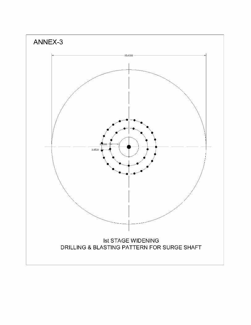
I. Open Excavation Access to surge shaft top will be made to remove overburden at surge shaft top. Slope stabilization works will follow surface excavation as per drawing and specification. After surface excavation and slope stabilization works a working platform around surge shaft at EL 504m will be prepared. II. Shaft Excavation Surge shaft will be excavated in three stages and it may be modified as per actual site condition and geology of rock. i) Pilot of 2.00m to 2.500m dia (stage 1) ii) Widening to 5.5m dia (stage 2) iii) Widening to 15.60m dia or 16.00m dia (stage 3). a) Pilot (stage 1) After establishing the center line of shaft, manual excavation will be taken up with 15 ton capacity gantry crane and steel bucket. Jack hammers will be used for drilling of pilot holes. Mucking will be done manually filling the steel bucket, which will be lifted by gantry crane and dispose off. Time schedule has been mentioned in our programme already submitted. b) Widening (stage 2 upto 5.5m) In 2nd stage the pilot will be widened to 5.5m dia. At the time of starting, 3 pull of 1.5m of 2nd stage will be excavated. After that 2nd stage and 3rd stage widening will be done on alternative days. c)2nd stage widening Data for 2nd stage widening is as under a) C/s area = 20.61sqm b) Nos of holes = 36 nos c) Est. advance = 1.50m d) Drill depth = 1.65m e) Total drilling = 60m f) Volume of solid rock (20.61sqm x 1.50m) = 31cum. Drilling for excavation will be done with 4 nos. Jack hammers at the rate of 6m/hrs. Total drilling time is 60m/(4nos x 6m/hr) = 2.5hrs.At the time of drilling, pilot hole will be covered with metal for safety. On completion of blasting, muck will be pushed into pilot hole manually.50% of muck will automatically fall into pilot hole while blasting. From the invert of tunnel, muck will be loaded with 0.90cum capacity excavator and transported in dumpers 18 ton assuming max. Lead as 1.40 km; time cycle for dumper is 2 trips/dumper/hrs: Total no. of dumper required is (31cum x 2.6T/cum)/(18T x 2 x 2hrs) = 1.12 nos provide 2 nos. Time cycle for 2nd stage widening is as under a) Marking profile = 0.50hr b) Drilling = 2.50hrs c) Charging/Blasting = 1.00hrs d) Mucking = 2.00hrs e) Miscellaneous = 1.50hrs.
Total = 7.5hrs.

Page 7 of 39
d) 3rd stage widening In this stage shaft will be widened to full size. Details of 3rd stage widening are as under-
Sl. No. Description
1 Minimum excavation 15.60m
2 C/s area 167.29sqm
3 No. of holes 188 nos
4 Estimated advance 1.50m
5 Drilling depth 1.65m
6 Total drilling 310m
7 Volume of solid rock 167.29 x 1.5 = 250.91cum
8 No. of jack hammers 11 nos
9 Total drilling time (310m)/(11nos x 8m/hr)=3.50 hrs
10 Excavation (proposed) Ex 100 – 1 no
11 Mucking time 250.91 x 1.6/(50) = 8 hrs
12 Excavation
a)Profile marking 1.00 hrs
b)Drilling 3.50 hrs
c)Charging/Blasting 2.00 hrs
d) Defume 0.50 hrs
e)Mucking 8.00 hrs
f)Misc 1.50 hrs
Total 16.50 hrs ≈ 1 day
13 Height 90.5 mt
14 Nos of pull(1.5) 60 nos.
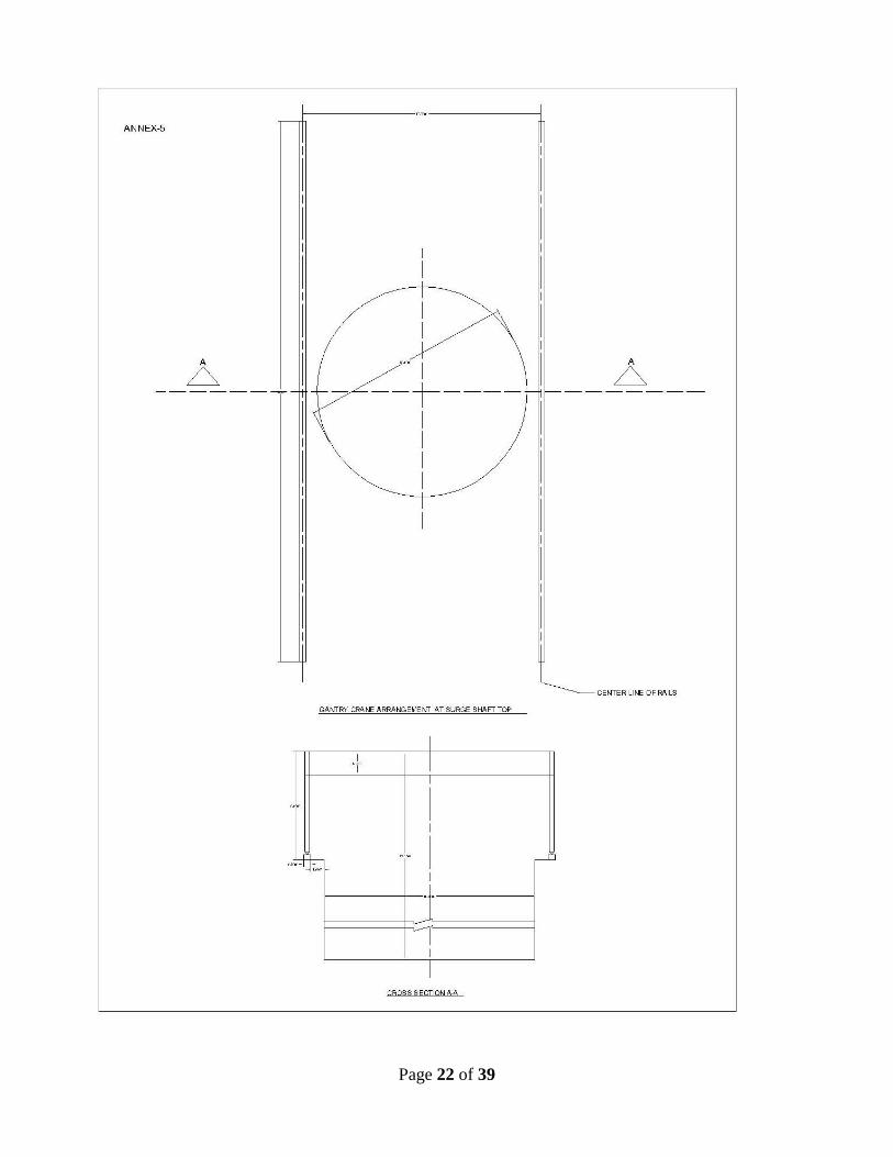
Muck will be pushed down through pilot hole with an excavator Ex 100 or equivalent. From the invert of tunnel, muck will be loaded with 0.9cum capacity excavator and transported in dumpers (10T).Assuming max lead as 1.40km, time cycle for is 2 trips/dumper/hr. Total no. of dumper required is (250.91cum x 2.6t/cum)/(18 ton x 2 x 10 hrs) = 1.81 nos ≈ 2 nos. In order to facilitate lowering of excavator into shaft and movement of men and materials, a 15 ton capacity gantry will be installed at shaft top. See Annex 3, 4 & 5. III) Rock support Surge shaft is to be provided with 25m dia x 5m long rock bolts @ 2000 mm c/c. Quantity of bolts per advance of 1.5m = (22 x 15.6 x 1.5)/(7 x 2 x 2) = 18.37 nos ≈ 20nos. Drilling length = 20nos x 5m = 100m drilling of rock bolts will be done with 8 nos jack hammers.100 m drilling will be done in 2.5 hrs. Total Bolting operation will be completed in 4 hrs. One advance involves (22/7) x 15.60 x 1.5m x 0.075 = 5.51cum of shotcrete. It will be conveyed to shaft top in Transit Mixer, lowered down to shaft in bucket with gantry crane and sprayed using aliva AL 262 or equivalent wet/dry shotcrete machine. This will be completed in 4 hrs. Rock Bolts and shotcrete will be done 6.5 hrs for an advance of 1.5 m. Another 12 hrs required for ribs and back fill concrete if required. Time cycle for and advance of 1.5m is as under -

Page 8 of 39
Day 1 – 1st & 2nd shift: Drilling, blasting and mucking (widening of final shape) Day 2 - 1st & 2nd shift: Rock support Day 2 2nd shift, Day 3 1st & 2nd shift: Drilling, Blasting and mucking (widening to 5.5m dia) Thus 1.5m depth of shaft sinking will be completed in 3 days i.e. 0.5m/day Therefore 90m shaft required = 180 days. IV. Lining 90.5m deep surge shaft will be lined (1.60m) from bottom to top in 1.5m lift using full circle slip form. Embedded parts will be placed in position and aligned before concreting operation. Concrete mixed in batching plant will be conveyed to shaft bottom by 4cum transit mixer and feeding of 2cum bucket. Bucket will be lifted with gantry crane and concrete placed into form and vibrated.
Lining cycle details are given below.
1. Lining thickness = 1.6m 2. Concreting per hr = 1.5m x 37.17 = 55.76cum 3. Height = 90.50m 4. Bucket capacity = 2.00cum 5. No. of bucket load = 46 nos 6. Concreting cycle
i) Lifting bucket @ 10m/min = 10min ii) Place into form 2cum = 15min iii) Lowering empty bucket = 10min iv) Miscellaneous position of bucket at pouring point etc = 5min
Total = 45min 7. Net cycle = 45min 8. Therefore no. of bucket/hr = 60/45 = 1.33nos 9. Time required for one lift = 55.76cum/(1.33 x 2) = 20.77hrs ≈ 1 day 10. Pour cycle = 4 days 11. Total time required = (90.50 x 4)/1.5 = 241 days. (Fixing of reinforcement steel has not been taken in account as it is to be done as a Parallel Activity of Concreting.) Alternatively we can use concrete pump of 30cum/ hr for pouring concrete from bottom of surge -shaft.
3. B/F VALVE CHAMBER I. ADIT: A 27m long adit emerged from Adit 3 leads to bottom of valve chamber. This Adit will be excavated full face to meet valve chamber of EL 405m.This adit will be completed in 7 days concurrent to HRT with same set of equipment. Rock support will follow tunnel excavation. II. VALVE CHAMBER Valve chamber will be excavated in the sequence as described below. Drilling will be done using jack hammer.
a. Stage1 A 4.00 x 3.50 D shaped pilot will be excavated from EL 405m with an upward slope of 2 in 1 to EL 418.5 and further horizontally to other end. During this stage temporary support required, if any, will be provided. This stage will be completed in 10 days. Muck will be pulled down with an excavator positioned on the slope for further loading into tippers.
b. Stage 2 In this stage entire length of chamber above the pilot from EL 418.5m to EL 422.00 will be excavated.

Page 9 of 39
This will be completed in 30 days. Muck will be manually pushed down to inclined pilot.
c. Stage 3 In this stage, chamber will be widened to EL 418.5.This stage will be completed in 20 days. Muck will be manually pushed down to inclined pilot.
d. Stage 4 On completion of stage 2 and 3 the excavation of stage 4 will be taken up and valve chamber will be benched to EL 418.5 to EL 405m. This stage excavation will be completed in 45 days Excavator Ex 100 or equivalent and 3 nos dumpers will be used. See Annex 6.
e. Rock Support Rock support measures will be taken up as per drawing and specification for crown and sides. Wagon drill will be used for drilling of rock bolts and drainage holes and bolt will be installed manually. Shotcrete will be sprayed using a wet shotcrete machine involved in HRT Tunnel work.
f. Concreting Upon completion excavation, columns will be raised in 2m lifts with 4 sets of shutters. PCC invert lining, pedestal and RCC beam in one month and entire concrete work will be completed in 3 months. Concrete will be pumped into forms.
4. PRESSURE SHAFT Circular shaped vertical steel lined pressure shafts of 3.4 m diameter emerging at EL 410.0m from the surge/valve chamber side to vertical about 55m and then horizontal to penstock bifurcation to power house units. These steel lined pressure shafts are then suitably connected to the scroll case of each unit in the power house to feed two units of 28MW each. Excavation of horizontal part of pressure shaft shall be taken up from adit-4 and excavation of vertical part of the pressure shaft shall be taken from Adit-3 by deploying set of equipment comprising loader/Excavator, jackhammers, gantry crane, dumpers, compressor etc. The mucking of vertical pressure shaft shall be done through Adit-3 by a gantry crane with bucket arrangement which is supposed to be installed on the top of vertical part of pressure shaft. Considering the cycle time of key equipments, shafts will be excavated at the schedule time. I. Rock support Installation during excavation. The rock supports in PS will be provided in the form of rock anchors. For drilling holes and fixing of rock bolts & anchors it is proposed. During each cycle of excavation the rock support installation will be carried out. Special attention will be made for installation of Rock anchors at crown. The holes will be drilled. The diameter of hole will be 1.5 times the diameter of bar. After drilling the hole will be cleaned by blowing out with compressed air & water. The anchor rods fabricated will have threaded ends for couplers. Where ever possible single rod of 3m / 4m will be installed. Alternatively 2 rods of 2.0m length will be installed with a coupler in between. After drying the hole with compressed air, thick consistent grout of cement with W/C ratio of 0.25 – 0.28 will be pumped using special grout pump till the entire hole gets filled up. Suitable water reducing admixtures will be used for achieving the required properties. The grout will be introduced into the end of the drilled hole through a pipe and will be gradually withdrawn as the hole is filled.
Page 10 of 39
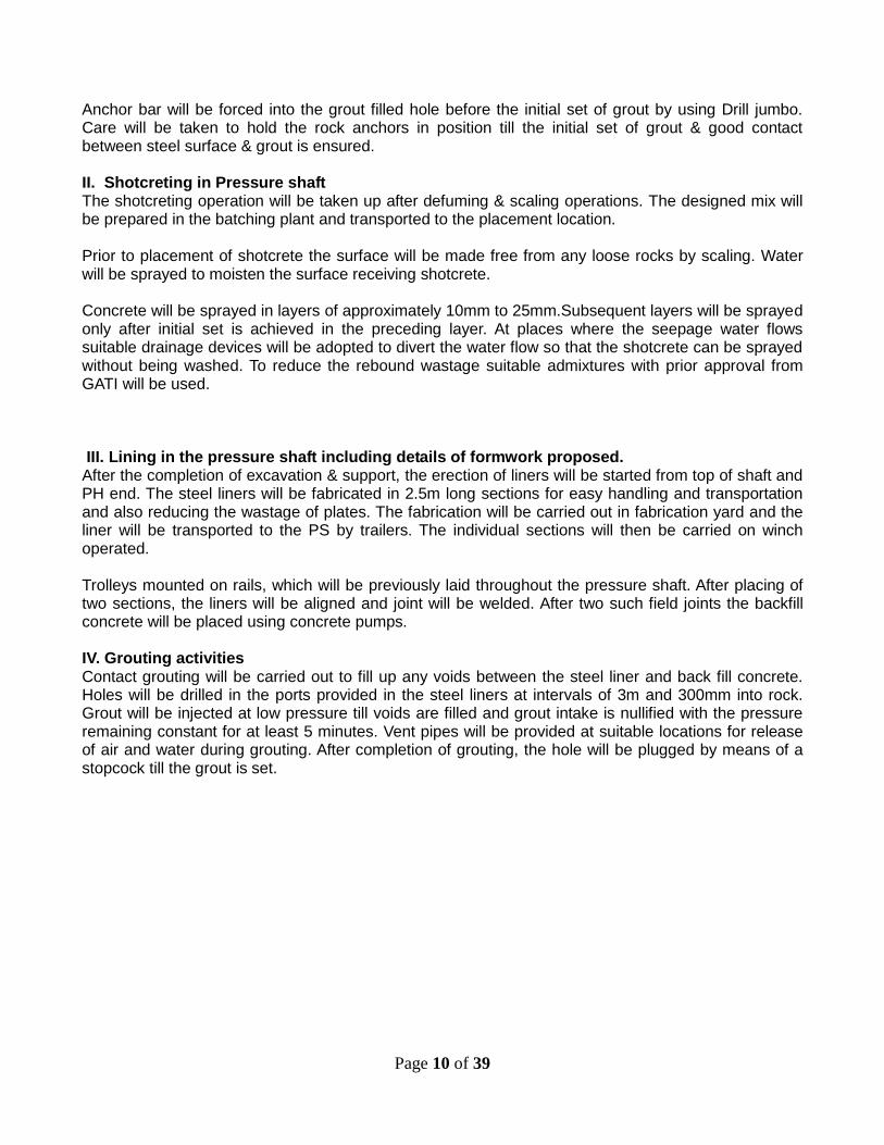
Anchor bar will be forced into the grout filled hole before the initial set of grout by using Drill jumbo. Care will be taken to hold the rock anchors in position till the initial set of grout & good contact between steel surface & grout is ensured. II. Shotcreting in Pressure shaft The shotcreting operation will be taken up after defuming & scaling operations. The designed mix will be prepared in the batching plant and transported to the placement location. Prior to placement of shotcrete the surface will be made free from any loose rocks by scaling. Water will be sprayed to moisten the surface receiving shotcrete. Concrete will be sprayed in layers of approximately 10mm to 25mm.Subsequent layers will be sprayed only after initial set is achieved in the preceding layer. At places where the seepage water flows suitable drainage devices will be adopted to divert the water flow so that the shotcrete can be sprayed without being washed. To reduce the rebound wastage suitable admixtures with prior approval from GATI will be used. III. Lining in the pressure shaft including details of formwork proposed. After the completion of excavation & support, the erection of liners will be started from top of shaft and PH end. The steel liners will be fabricated in 2.5m long sections for easy handling and transportation and also reducing the wastage of plates. The fabrication will be carried out in fabrication yard and the liner will be transported to the PS by trailers. The individual sections will then be carried on winch operated. Trolleys mounted on rails, which will be previously laid throughout the pressure shaft. After placing of two sections, the liners will be aligned and joint will be welded. After two such field joints the backfill concrete will be placed using concrete pumps. IV. Grouting activities Contact grouting will be carried out to fill up any voids between the steel liner and back fill concrete. Holes will be drilled in the ports provided in the steel liners at intervals of 3m and 300mm into rock. Grout will be injected at low pressure till voids are filled and grout intake is nullified with the pressure remaining constant for at least 5 minutes. Vent pipes will be provided at suitable locations for release of air and water during grouting. After completion of grouting, the hole will be plugged by means of a stopcock till the grout is set.

Page 11 of 39
5.RIVER DIVERSION Before taking up Dam and its Appurtenant works the river water handling to control river diversion will be taken up, The coffer dam construction at upstream will be constructed, first excavating partially elevation of river Alluvium in the left bank for diversion channel to guide the water through diversion Channel. Subsequently the u/s cofferdam will partially be constructed to close to divert the water through the diversion channel. The construction of retaining walls at d/s and u/s shall be taken up with remaining construction of cofferdam- A. The cofferdam- A thereafter shall be removed and construction of coffer dam B & C shall be completed this shall be a part of 3rd stage of river diversion. Under 4th stage removal of coffer dam B up to 445m level shall be taken up with retaining wall of u/s and thereafter removal of cofferdam C and retaining wall of cofferdam. The details of activities in 4 phases of execution are as under:

Page 12 of 39

Page 13 of 39
Phase –IV : River flow through the Spillway bays 2 & 3 (non -monsoon)
1. Removal of Cofferdam “B” at El 445.
2. Removal of u/s Cofferdam and Retaining Wall.
3. Total removal of Cofferdam “C” Total removal of d/s cofferdam retaining wall and final rip-rap protection (after spillway gates are closed for reservoir impounding). Proposed Construction of cofferdams shall be with Clay rock, graded filter material, compacted rock and random rock fill. The cofferdam will be constructed in stages: (Coffer dam A, Coffer dam B & C). The stages are as follows:
I. Stage I: Cofferdam The random rock fill materials obtained from excavation dam abutment will be dumped directly along the alignment of cofferdam from right bank. The cofferdam will be constructed by end on method. Embankment materials will be transported by dumped at the end to form stockpiles. Dozers will be deployed to push stockpiles along the alignment of cofferdam. As the embankment proceeds to meet the left bank, big size boulders obtained from excavation will be placed to reduce washout of materials. The rock fill materials will be rolled and compacted using Vibro-Compacting Roller. Impervious materials will be dumped on the upstream side of the u/s cofferdam & d/s cofferdam.
II. Stage II: Cofferdam

Page 14 of 39
Once the river flow is blocked after Stage I filling, dewatering and cleaning of foundation bed will be done. Excavation of trench for u/s cofferdam and for u/s cofferdam and d/s cofferdam will be taken up. The excavated trench will be filled with Zone I material and compacted up to the bed level. The imperious material (Zone I) will be placed in layers of 40 cm and compacted to 30 cm with at least six passes using 10 ton rollers. Zone 4 materials obtained from excavation will be dumped directly on both sides of Zone 1 filling. The heights of Zone 1 & Zone 4 will be maintained at same level during execution with Zone 2 materials placed in between. A small transverse slope will be provided from center towards edges to avoid pooling of water. The sequence of filling will continue till top level is reached. The equipments, used for diversion channel will be used in Cofferdam construction. However the following additional equipments are proposed to be deployed for the construction of Coffer Dam. Required Machinery for compaction 1. Dozer BD-50 or, equivalent. 2. Vibrator compactor 10T capacity. 3. Water Tanker 6000 Ltrs. III. DAM RIVER BED EXCAVATION AND CARE OF WATER The excavation in the riverbed section for dam will be taken up after the completion of river diversion works. On partial completion of coffer dam–A, while the river flow shall be left bank open channel the part excavation of intake and spillway in the right abutment shall be taken up. On completion of total cofferdam, the excavation of spillway foundation shall be completed. Construction of spillway-2, 3 and half way – 1, intake structure, spillway piers – 1, 2 & 4, stilling basin shall be taken up along partial construction of coffer dam B. On completion of above, the removal of u/s and d/s coffer dam along with construction of cofferdam – B & C shall be taken up. During this phase river shall be diverted to flow through spillways – 2 & 3 and excavation of spillway and concrete gravity dam shall be taken up. During Non – Monsoon period when river flows through spillway 2, 3 the work of removal of cofferdam B upto EI 445m, removal of u/s cofferdam retaining, final removal of cofferdam – C shall be done along with final removal of d/s cofferdam retaining wall and closing up of spillway gates. IV. FOUNDATION EXCAVATION After the initial dewatering, the overburden material will be removed by deploying excavators/loaders & dumpers till the rock surface are exposed. Further excavation in rock will be carried out by conventional drilling and blasting method using drills for drilling. The dewatering will be carried out after diversion and closure of cofferdam. Trenches and sumps will be provided near the cofferdams to collect the water. Submersible pumps with high lift capacity capable of removing slush and grit will be provided along with regular dewatering pumps. As the excavation proceeds, depth wise the slump locations will be modified accordingly. If required double stage pumping will be provided. The following high head pumps will be deployed for dewatering works. Sufficient capacity of pumps shall be kept to ensure proper dewatering at site. Necessary inventory of spares will be provided at site so that the pump runs continuously without fail.
Page 15 of 39
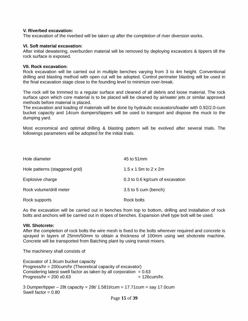
V. Riverbed excavation: The excavation of the riverbed will be taken up after the completion of river diversion works. VI. Soft material excavation: After initial dewatering, overburden material will be removed by deploying excavators & tippers till the rock surface is exposed. VII. Rock excavation: Rock excavation will be carried out in multiple benches varying from 3 to 4m height. Conventional drilling and blasting method with open cut will be adopted. Control perimeter blasting will be used in the final excavation stage close to the founding level to minimize over-break. The rock will be trimmed to a regular surface and cleaned of all debris and loose material. The rock surface upon which core material is to be placed will be cleaned by air/water jets or similar approved methods before material is placed. The excavation and loading of materials will be done by hydraulic excavators/loader with 0.92/2.0-cum bucket capacity and 14cum dumpers/tippers will be used to transport and dispose the muck to the dumping yard. Most economical and optimal drilling & blasting pattern will be evolved after several trials. The followings parameters will be adopted for the initial trials. Hole diameter 45 to 51mm Hole patterns (staggered grid) 1.5 x 1.5m to 2 x 2m Explosive charge 0.3 to 0.6 kg/cum of excavation Rock volume/drill meter 3.5 to 5 cum (bench) Rock supports Rock bolts As the excavation will be carried out in benches from top to bottom, drilling and installation of rock bolts and anchors will be carried out in slopes of benches. Expansion shell type bolt will be used. VIII. Shotcrete: After the completion of rock bolts the wire mesh is fixed to the bolts wherever required and concrete is sprayed in layers of 25mm/50mm to obtain a thickness of 100mm using wet shotcrete machine. Concrete will be transported from Batching plant by using transit mixers. The machinery shall consists of Excavator of 1.9cum bucket capacity Progress/hr = 200cum/hr (Theoretical capacity of excavator) Considering latest swell factor as taken by all corporation = 0.63 Progress/hr = 200 x0.63 = 126cum/hr. 3 Dumper/tipper – 28t capacity = 28t/ 1.581t/cum = 17.71cum = say 17.0cum Swell factor = 0.80

Page 16 of 39
Bulk volume = 17 x .080 = 13.6 cum Cycle time Spotting time = 1.0min Loading time = 4.00min Average lead = 2.0km Loaded haul (20km/hr) 2 x 60/20 = 6.0min Unloading = 1.0min Empty haul (25km/hr) 2 x 60/25 = 4.80min Total cycle time = 16.80 say = 17.00min Nos of trip in 50min working hr = 50/17 = 3.0 no Output of Dumper per working hr = 13.6cum x 3.0 = 40.80cum 3.One dozer of 280HP Progress/hr = 150cum/hr. The following main machinery shall be deployed for CARE OF WATER – DAM – INTAKE-BARRAGE WORKS. Hydraulic Excavator – 1.9cum capacity = 2 nos. Compressor, screw type = 600 cfm capacity Dumpers 18 ton capacity = 8nos Dozer BD 50 or equivalent = 1nos Batching plant – 60cum/hr capacity = 1 nos Batching plant – 30cum/hr capacity = 1 nos (which will be shared with Adit-1) Work and machinery has been planned to be completed as shown in time schedule.
6. INTAKE The excavation of Inlet structure shall be taken up from top to bottom with conventional drilling blasting & mucking. Simultaneously rock bolting and shotcreting will be done to support the slopes during excavation. Concreting will be done using Batching plant, mixers & concrete pumps. Steel scaffoldings will be provided for shuttering and insert works.
7. POWER HOUSE The excavation of power house will start with the commencement of work as per the excavation Plan provided with the design drawings. Suitable slopes and berms will be developed to arrest the ground failure at the crown. The excavation will be done as per the drawings and support system comprising rock bolt and shotcrete with wire mesh will be provided as the excavation proceeds. The works shall be continuous unless or until the water due to flooding of monsoons disrupt the excavation. The excavation shall be strictly executed as per benching and excavation plan shown from top to bottom. The excavation will be started from top by deploying machinery as listed below. Drilling and blasting will be carried out to remove hard rock. The bench will be developed from top to bottom. The slope between each bench will be provided with necessary rock bolt wire mess and shotcrete as the rock is exposed to required line. On completion of rock supports the excavation of next bench will be taken up and so on. It is proposed to have each bench of till excavation is completed up to service bay level.

Page 17 of 39
The boxed excavation of power house will be formed and excavation of unit pit will be taken up by lowering ramp to excavate the pit of units. The excavation which shall be not possible through ramp shall be done by widening of draft tube and tail channel. Necessary rock supports of rock bolt and shotcrete will be provided. Drilling for rock bolts of 25 & 36mm dia and 3 to 8m in length will be done by deploying jack hammers and pusher legs.6 Nos of drilling machines shall be deployed to drill holes for rock bolt. Drilling for rock bolting shall be followed on completion of excavation. On installation of rock bolt, fixing of wire mess shall be taken up and thereafter required thickness of shotcrete shall be sprayed. Initial coat of shotcrete wherever necessary as per rock strata will be sprayed before rock bolting. Rock bolter free from diversion Channel shall be used for drilling and rock bolting of power house area where. Two EOT cranes is provided at service bay and unloading bay. The transmission towers take off from the roof of GIS floor hence no separate arrangement for switchyard has been made.
I. Main Equipment Excavator/loader Dumpers - 10cum capacity Jack hammers & pusher leg - 6 nos Concrete pump - 30cum/hrs Batching plant - 30cum/hrs Transit mixer - 4 cum Compressor - 600cfm.
8. CRUSHER PLANT One Crusher Plant of 150 TPH shall be installed at upstream of Rorathang Concrete Bridge to produce required quantities of aggregates of all sizes. The Sand screening system is in-built in the said stone crusher plant. The boulders from reservoir area at the upstream of dam shall be collected for aggregate production. Excavated material from HRT, Dam or any Excavation in project shall be used for aggregate production if found suitable. One Excavator (EX200 or, equivalent) shall be deployed for the collection of boulders and feeding the same at the greezly feeder of crushing plant. One Loader will also be used for loading of aggregate in tippers. 6 nos of Tippers shall be deployed for transportation of aggregate to batching plants. 4 nos of tippers shall be feeding aggregates to Batching plant of Dam & Adit-1 and rest of 2 shall be feeding to Adit-2, Surge Shaft and Adit-3/Power house batching plants. I. List of main Machineries at Crusher Plant:
i. 150 TPH Crusher Plant :1 Set. ii. Excavator (Ex-200 or equivalent) :1 No. iii. 10T capacity Tippers: :6 Nos iv. Loader 2 cum bucket :1 No.

KEY DATE OF H.R.T. AS PER REVISED CONSTRUCTION PROGRAMME (Excavation Details)
Annex-I
Adit-1
Adit-2
Adit-3 July'10
July'10
July'10
Start
Start
Start
80 m
477 m
262 m
Mar'12 Finish
Mar'12 Finish
Feb'11 Start
Feb'11 Start
Mar'12 Mar'12 Finish Finish
Mar'11 Start
face-I
face-II face-III
face-IV Nov'10
Start
1239 m(appr.) 1334 m(appr.) 1063 m(appr.) 944 m(appr.)
RD- 0.000
RD- 1239 (May Vary)
RD- 2573
RD- 3636 (May Vary) RD- 4580

Page 19 of 39
KEY DATE OF H.R.T. AS PER REVISED CONSTRUCTION PROGRAMME (Tunnel Lining )
Annex-II
Adit-1
Adit-2
Adit-3
80 m
477 m
262 m
28-05-12 Finish
05-10-12 Finish
30-09-12 Finish
12-06-12 Start
Invert Concrete face-I
face-II face-III
face-IV
Overt Concrete
13-04-12 Start
29-12-12 Finish
04-12-12 Finish
28-04-12 Start
2573 m 2007 m
RD- 0.000
RD- 2573
RD- 4580

Page 21 of 39
Page 22 of 39

ANNEX-7

Page 25 of 39
CONSTRUCTION PROGRAMME FOR DAM & SPILLWAY
Page 26 of 39
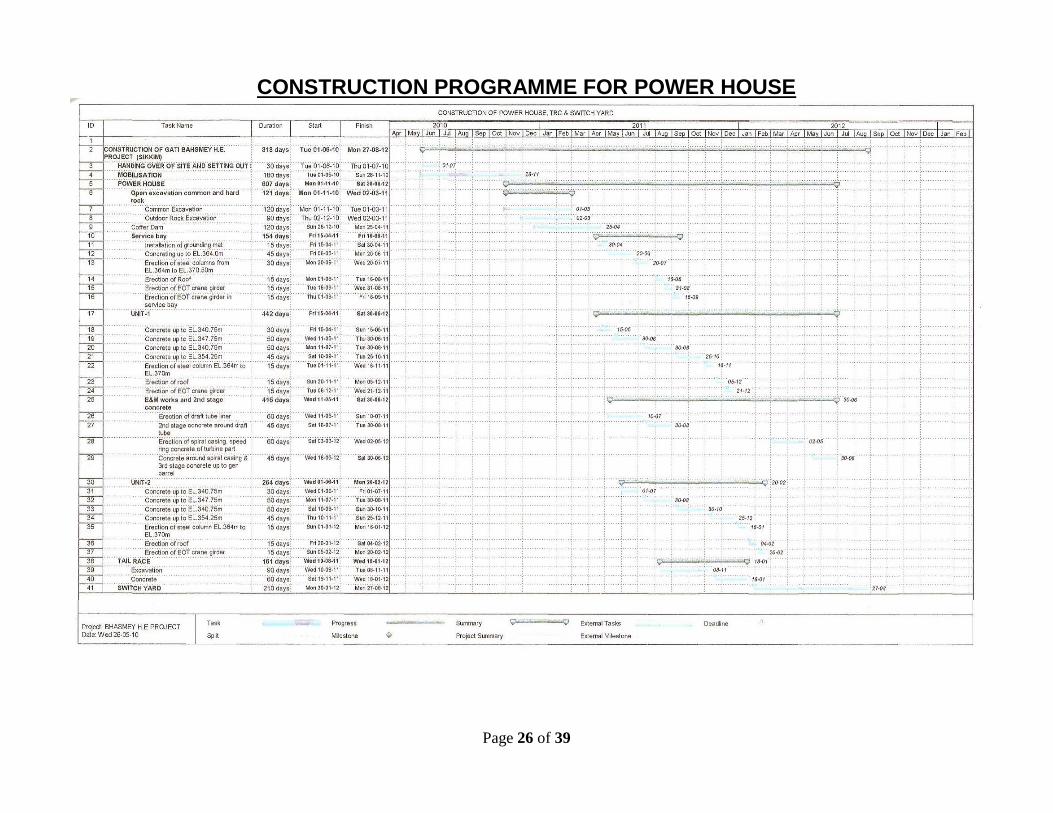
CONSTRUCTION PROGRAMME FOR POWER HOUSE

Page 27 of 39
CONSTRUCTION PROGRAMME FOR HRT, SURGE SHAFT, & VALVE CHAMBER

Notes
This programme is subjected to the followings: 1. All the construction drawings should be available minimum 90 days prior to start of
the activities.
2. All the client issue materials should be made available in time.
3. All the embedded parts supplied by the E&M & H.M. contractors should be available
in time.
4. This Programme is subjected to the extra-ordinary climatic conditions like as Land
Slides, Flood, Earth-quake etc.
5. Site should be free from hindrances like as Local Disturbances etc..
6. Payments should be released in time.
7. The 2nd Stage concrete of Power House can only be finalised after obtaining the
erection schedule of Draft tube Liner, Scroll Case, Spirals, Generator Barrel etc. by
the E & M Agency.

BHASMEY HYDRO ELECTRIC PROJECT
LII PROPOSED SUMMARIZE EQUIPMENT MOBILIZATION LIST
SI No. Project component /
equipment Specification
Nos. Suggested by Remarks
Gati Simplex
1 Batching Plant 60 Cum / hr 1 1
2 Batching Plant 30 Cum / hr 1 3
3 Batching Plant 15 Cum / hr 3 3 We will use 3 nos 10/7 Mixture M/C at Surge Shaft
4 Dozer 1.5 Cum 2 2
5 Vibratory compactor 10 Ton 1 1
6 Crushing Plant 150 TPH 1 1
7 Sand screening Plant 1 - Facility available with Crushing Plant
8 Excavator EX-200 or similar, bucket 1.9-2.00 capacity
5 4
9 Excavator EX-100 (modified boom) 5 4
10 Excavator EX-65 or similar 2 2 EX-70
11 Dumpers 28 MT-16 cum OR 18 MT - 6 Cum
14 11
12 Dumpers 10 MT-18 MT 15 20
13 Tippers 6 MT 6 3
14 Trailer For shifting ferrules & steels etc
2 -
15 Concrete Pump 30 Cum capacity (7-elect. & 4 may be diesel)
11 6
16 Transit mixer 6 Cum. Capacity 8 6
17 Transit mixer 4 Cum. Capacity 9 12
18 Grout machine multipurpose High Pr. Grout (use for face pre grout/consolidation grout)
1 1
19 Grout Pump 7 4
20 JCB/JD 3D or equivalent 2 2
21 Tower crane 1 1
22 Mobile crane / Hydra Mobile Crane-40T, Hydra-12T
3 3
23 Compressor 600 cfm 5 5
24 Compressor Above 600 cfm 1 -
25 Jack Hammer with pusher leg 24 26
26 Concrete boom placer (If available) 1 -
27 Core drilling machine 1 - Separate Agencyis to be deployed
28 Crimping machine 1 1

Page 30 of 39
SI No. Project component /
equipment Specification
Nos. Suggested by
Remarks
29 Lathe machine 1 1
30 Dry shotcrete machine 1 1
31 Dewatering Pump - 5HP - 3/4 Nos.
5 HP (Preferably sump pump)
3
4
32 Dewatering Pump - 10HP - 3/4 Nos.
10 HP (Preferably sump pump)
3
33 Dewatering Pump - 20/25 HP - 1/2 Nos.
20/25 HP (Preferably sump pump)
2
34 Dewatering Pump (For Face) 3 / 5 HP ( Pneumatic) 7 3 Electrical
35 Deawatering Pumps 20HP-65HP 6 3 80 HP
36 Rib bending machine 100Ton 2 1
37 Welding Machine (Workshop/fab. Shop)
Heavy duty 2 2
38 Welding Machine 400 Amp 13 9
39 Gas cutting sets Required at every fronts 13 21
40 Bar cutting machine 2 2
41 Bar bending machine 2 2
42 Hydraulic Jumbo drilling machine
May be single arm boom 1 -
43 Hydraulic Jumbo drilling machine
Preferablly Double boom arm
3 3
44 DG 315-600 Kva 4 4
45 D.G. 250 Kva 6 1
46 D.G. 125 Kva 2 -
47 Blower fans with motors 20 HP 14 - As per Designer's Recommendation
48 Blower fans with motors 10 HP X 2 14 -
49 Paving Breaker 6 -
50 Shotcrete Machine wet (robotic arm) 2 2
51 Shotcrete Machine wet (hand spray nozzle) 3 3
52 Concrete Placer Pneumatic 5 5
53 Gantry 6.00 meter each 8 4 6 M each
54 Shutter Vibrators (For Gantry) 5 each + 1 spare 44 16 4 for each Gantry
55 Slip form shuttering 1.50 meter height 1 1
56 Gamzen conc. Mixer 10/7 concrete mixer 4 3
57 Winch / Gantry ( 15 T capacity) along with buckets
15 T capacity 2 1
58 Rectifier, for welding (20 A DC current Output )
3 -
59 Jacks, chain blocks, tufrider -

Page 31 of 39
etc
SI No. Project component /
equipment Specification
Nos. Suggested by
Remarks
60 Scissor lift 2 3
61 Sieve analysis equipment 1 1
62 Core testing equipment 2 2
63 Concrete compressive strength
1 2
64 Pull out test machine 2 1
65 Torque Wrench 5 1
66 Cube moulds 63
67 S/Crete Panels -
68 Permeability test equipment 1 1
69 Dumpy level Sokkia 2 2
70 Total Station Sokkia 3 3
71 Water tanker 3 3
72 Diesel Pump 1 -
73 Diesel filling Tankers 2 1
74 Explosives van 2 1
75 Stoppers 3 -
76 Starter with needle vibrators -
77 Weigh Bridge 40T 1 1
Apart from above, machineries may be increased/decreased as per site requirement.

BHASMEY HYDRO ELECTRIC PROJECT
LII PROPOSED EQUIPMENT MOBILIZATION LIST
SI No. Project component / equipment Specification
Nos Suggested by Remarks
Gati Simplex
A Dam works
A.1 Batching Plant Unit-1 > 60 Cum / hr 1 1
A.2 Batching Plant Unit-2 30 Cum / hr Shared with Adit-1.
A.3 Dozer 1.5 Cum 1 1
A.4 Vibratory compactor 10 Ton capacity 1 1
A.5 Sand screening Plant 1 - Incorporated with Crusher Plant.
A.6 Excavator EX-200 or similar, bucket 1.9-2.00 capacity 3 3 1 may be shared at Crusher plant
A.7 Dumpers (8 - 10 req. as per dumping) 28 MT-16 cum OR 18 MT - 6 Cum 8 8
A.8 Concrete Pump (3+1 standby) 30 Cum / hr 4 2 Pump from Surge shaft may be used initially.
A.9 Transit mixer 6 Cum. Capacity 5 6
A.10 Grout Pump 2 2
A.11 JCB/JD 3D or Equivalent 1 1
A.12 Tower crane 1 1
A.13 Mobile crane 40 Ton Capacity 1 1
A.14 Compressor 600 cfm 1 1 1 Addl. 300 cfm compressor will be deployed at Dam Site.
A.15 Jack Hammer with pusher leg 4 4
A.16 Concrete boom placer (If available) 1 Not mentioned during Tendering.
A.17 Core drilling machine 1 - Separate Agency will be deployed in later stage.
A.18 Welding machine 400 Amp 2 3
A.19 Gas cutting sets 4 4
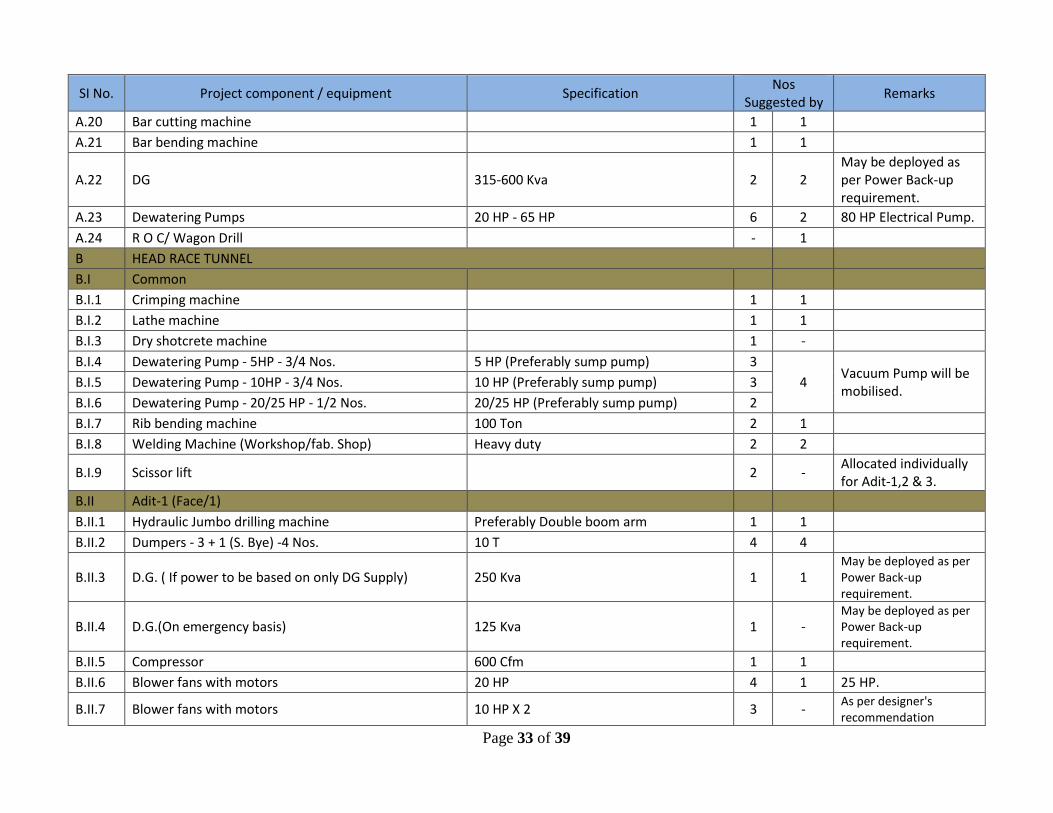
Page 33 of 39
SI No. Project component / equipment Specification Nos
Suggested by Remarks
A.20 Bar cutting machine 1 1
A.21 Bar bending machine 1 1
A.22 DG 315-600 Kva 2 2 May be deployed as per Power Back-up requirement.
A.23 Dewatering Pumps 20 HP - 65 HP 6 2 80 HP Electrical Pump.
A.24 R O C/ Wagon Drill - 1
B HEAD RACE TUNNEL
B.I Common
B.I.1 Crimping machine 1 1
B.I.2 Lathe machine 1 1
B.I.3 Dry shotcrete machine 1 -
B.I.4 Dewatering Pump - 5HP - 3/4 Nos. 5 HP (Preferably sump pump) 3
4 Vacuum Pump will be mobilised.
B.I.5 Dewatering Pump - 10HP - 3/4 Nos. 10 HP (Preferably sump pump) 3
B.I.6 Dewatering Pump - 20/25 HP - 1/2 Nos. 20/25 HP (Preferably sump pump) 2
B.I.7 Rib bending machine 100 Ton 2 1
B.I.8 Welding Machine (Workshop/fab. Shop) Heavy duty 2 2
B.I.9 Scissor lift 2 - Allocated individually for Adit-1,2 & 3.
B.II Adit-1 (Face/1)
B.II.1 Hydraulic Jumbo drilling machine Preferably Double boom arm 1 1
B.II.2 Dumpers - 3 + 1 (S. Bye) -4 Nos. 10 T 4 4
B.II.3 D.G. ( If power to be based on only DG Supply) 250 Kva 1 1 May be deployed as per Power Back-up requirement.
B.II.4 D.G.(On emergency basis) 125 Kva 1 - May be deployed as per Power Back-up requirement.
B.II.5 Compressor 600 Cfm 1 1
B.II.6 Blower fans with motors 20 HP 4 1 25 HP.
B.II.7 Blower fans with motors 10 HP X 2 3 - As per designer's recommendation

Page 34 of 39
SI No. Project component / equipment Specification Nos
Suggested by Remarks
B.II.8 Jack Hammer with pusher leg 2 2
B.II.9 Paving Breaker - 2 Nos. 2 -
B.II.10 Shotcrete Machine wet (preferably robotic) 1 1
B.II.11 Concrete Placer Pneumatic 1 1
B.II.12 Concrete Pump Electrical -30 Cum. /hr 1 1
B.II.13 Gantry 6.00 meter each 2 -
B.II.14 Shutter Vibrators (For Gantry) 5 each + 1 spare 11 -
B.II.15 Grout machine multipurpose High Pr. Grout (use for face pre grout/consolidation grout)
1 - Shared with Dam.
B.II.16 Transit mixer 4 Cum. Capacity 3 3
B.II.17 B/Plant May be shared from Adit-2 / Dam 1 Shared with Dam.
B.II.18 Gamzen conc. Mixer 10/7 Concrete mixer 1 1
B.II.19 Excavator OR Loader Ex-100 or equivalent 1 1
B.II.20 Dewatering Pump (For Face) 3 / 5 HP ( Pneumatic) 2 1 May be increased if required
B.II.21 Welding Machine Electrical 2 1
B.II.22 Gas cutting sets 2 4
B.II.23 Scissor Lift - 1
B.III Adit-2 (Face/2 & 3)
B.III.1 Hydraulic Jumbo drilling machine Preferably Double boom arm 1 1
B.III.2 Dumpers - 3 + 1 (S. Bye) -4 Nos. 10 T 4 4
B.III.3 D.G. ( If power to be based on only DG Supply) 250 Kva 1 1 May be deployed as per Power Back-up requirement.
B.III.4 D.G.(On emergency basis) 125 Kva 1 - May be deployed as per Power Back-up requirement.
B.III.5 Compressor 600 Cfm 1 1
B.III.6 Blower fans with motors 20 HP 4 2 As per designer's recommendation
B.III.7 Blower fans with motors 10 HP X 2 5 - As per designer's recommendation

Page 35 of 39
SI No. Project component / equipment Specification Nos
Suggested by Remarks
B.III.8 Jack Hammer with pusher leg 2 4
B.III.9 Paving Breaker - 2 Nos. 2 -
B.III.10 Shotcrete Machine May be shared from Adit-1 1 Wet S/C hand spray nozzle
B.III.11 Concrete Placer Pneumatic 2 2
B.III.12 Concrete Pump Electrical -30 Cum. /hr 2 1 Common for Both HRT faces.
B.III.13 Gantry (6.00 meter X 2 Nos. X 2 Faces) 6.00 meter each 4 1 1 no of 10m length.
B.III.14 Shutter Vibrators (For Gantry) (5 each + 1 spare) x 2 faces 22 8 Common for Both HRT faces.
B.III.15 Grout machine (For each faces after compl. Of excavation)
2 1
B.III.16 Transit mixer 4 Cum. Capacity 3 3
B.III.17 B/Plant 15 Cum /Hr 1 1 30 Cum/Hr.
B.III.18 Gamzen conc. Mixer 10/7 Concrete mixer 1 1
B.III.19 Excavator OR Loader Ex-100 or equivalent 1 2 Individually for each HRT faces.
B.III.20 Dewatering Pump (For Face) 3 / 5 HP ( Pneumatic) 3 1 Electrical.
B.III.21 Welding Machine Electrical 3 2
B.III.22 Gas cutting sets 3 4
B.III.23 Scissor Lift - 1
B.IV Adit-3 (Face/4, access to PS,SS)
B.IV.1 Hydraulic Jumbo drilling machine Preferably Double boom arm 1 1
B.IV.2 Dumpers - 3 + 1 (S. Bye) -4 Nos. 10 T 4 4 May be increased if required.
B.IV.3 D.G. ( If power to be based on only DG Supply) 250 Kva 1 1 May be deployed as per Power Back-up requirement.
B.IV.4 D.G.(On emergency basis) 125 Kva 1 - May be deployed as per Power Back-up requirement.
B.IV.5 Compressor 600 Cfm 1 1

Page 36 of 39
SI No. Project component / equipment Specification Nos
Suggested by Remarks
B.IV.6 Blower fans with motors 20 HP 4 1
B.IV.7 Blower fans with motors 10 HP X 2 3 - As per designer's recomendation
B.IV.8 Jack Hammer with pusher leg 2 - To be shard with other Adits
B.IV.9 Paving Breaker - 2 Nos. 2 -
B.IV.10 Shotcrete Machine wet (preferably robotic) 1 1
B.IV.11 Concrete Placer Pneumatic 1 1
B.IV.12 Concrete Pump Electrical -30 Cum. /hr 1 1
B.IV.13 Gantry 6.00 meter each 2 1 10 Mtr Length.
B.IV.14 Shutter Vibrators (For Gantry) 5 each + 1 spare 11 8
B.IV.15 Grout machine multipurpose High Pr. Grout (use for face pre grout/consolidation grout)
1 1
B.IV.16 Transit mixer 4 Cum. Capacity 3 3
B.IV.17 B/Plant 15 Cum /Hr 1 1 30 Cum/Hr.
B.IV.18 Gamzen conc. Mixer 10/7 Concrete mixer 1 1
B.IV.19 Excavator OR Loader Ex-100 or equivalent 1 1
B.IV.20 Dewatering Pump (For Face) 3 / 5 HP ( Pneumatic) 2 1 May be increased if required.
B.IV.21 Welding Machine Electrical 400 Amp 2 1
B.IV.22 Gas cutting sets 2 2
B.IV.23 Scissor Lift - 1
C SURGE SHAFT
C.1 Jack hammers (4 and 2 spare) Along with 2/3 pusher legs 6 11 May be increased if required.
C.2 Loader OR Excavator (At Surge bottom) EX-100 (modified boom) 1 -
C.3 Excavator (Inside surge shaft) Small model 1 1 EX 70.
C.4 Dumper 10 Ton capacity 3 2
May be increased depending upon Dumping yard location.

Page 37 of 39
SI No. Project component / equipment Specification Nos
Suggested by Remarks
C.5 Slip form shuttering 1.50 meter height 1 1
C.6 Welding machine Electrical 2 2
C.7 Winch / Gantry ( 15 T capacity) along with buckets 15 T capacity 1 1 With Trolley.
C.8 Concrete Pump (At time of concrete) 30 Cum / hr 1 1 Shared with Valve House.
C.9 Grout machine 1 1
C.10 Gas cutting sets 2 2
C.11 Shotcrete machine wet ( wet, hand spray nozzle) 1 1 Dry S/C machine.
D Pressure Shaft / Pressure Tunnel
D.1 Hydraulic Jumbo drilling machine (for horizontal portion)
May be single arm boom 1 - ROC from Power house will be used.
D.2 Compressor ( for PS top, Bottom may be shared from Power House)
1 - Compressor from Power House will be used.
D.3 DG set ( for PS top, Bottom may be shared from Power House)
250 Kva 1 Compressor from Power House will be used.
D.4 Jack hammers (4 and 2 spare) Along with 2/3 pusher legs 6 6
D.5 Winch / Gantry (For PS top) along with buckets 10T capacity 1 5 Ton capacity Gantry with bucket.
D.6 Rectifier, for welding (20 A DC current Output ) - 3 Nos. -
D.7 Hydra 12 T 1 1
D.8 Jacks, chain blocks, tufrider etc -
D.9 Excavator / loader EX-65 with modified boom 1 -
D.10 Excavator (From Adit-4) EX-100 (modified boom) 1 1 1 No EX-70 will be used.
D.11 Dumper (3 + 1 standby) 6 T capacity 4 3
D.12 Grout machine 1 - will be used from Power
House.
D.13 Gas cutting sets 2 2
D.14 Welding Machine 400 Amp 2 - will be used from Power House.
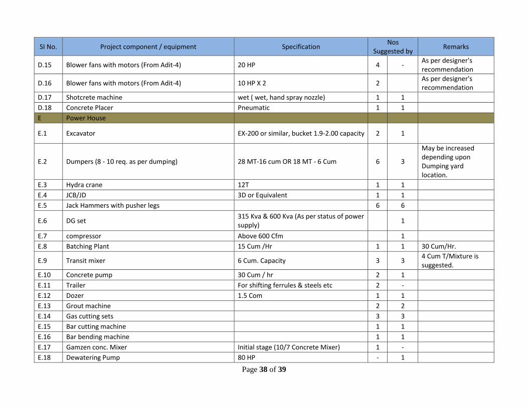
Page 38 of 39
SI No. Project component / equipment Specification Nos
Suggested by Remarks
D.15 Blower fans with motors (From Adit-4) 20 HP 4 - As per designer's recommendation
D.16 Blower fans with motors (From Adit-4) 10 HP X 2 2 As per designer's recommendation
D.17 Shotcrete machine wet ( wet, hand spray nozzle) 1 1
D.18 Concrete Placer Pneumatic 1 1
E Power House
E.1 Excavator EX-200 or similar, bucket 1.9-2.00 capacity 2 1
E.2 Dumpers (8 - 10 req. as per dumping) 28 MT-16 cum OR 18 MT - 6 Cum 6 3
May be increased depending upon Dumping yard location.
E.3 Hydra crane 12T 1 1
E.4 JCB/JD 3D or Equivalent 1 1
E.5 Jack Hammers with pusher legs 6 6
E.6 DG set 315 Kva & 600 Kva (As per status of power supply)
1
E.7 compressor Above 600 Cfm 1
E.8 Batching Plant 15 Cum /Hr 1 1 30 Cum/Hr.
E.9 Transit mixer 6 Cum. Capacity 3 3 4 Cum T/Mixture is suggested.
E.10 Concrete pump 30 Cum / hr 2 1
E.11 Trailer For shifting ferrules & steels etc 2 -
E.12 Dozer 1.5 Com 1 1
E.13 Grout machine 2 2
E.14 Gas cutting sets 3 3
E.15 Bar cutting machine 1 1
E.16 Bar bending machine 1 1
E.17 Gamzen conc. Mixer Initial stage (10/7 Concrete Mixer) 1 -
E.18 Dewatering Pump 80 HP - 1

Page 39 of 39
SI No. Project component / equipment Specification Nos
Suggested by Remarks
F Laboratory
F.1 Sieve analysis equipment 1 1
F.2 Core testing equipment 2 2
F.3 Concrete compressive strength 1 2
F.4 Pull out test machine 2 1
F.5 Torque Wrench 4 1
F.6 Cube moulds 63
F.7 S/Crete Panels
F.8 Permeability test equipment 1 1
F.9 Slump Test Apparatus with Temping Rod - 3
G General
G.1 Water tanker 6000 Ltrs 3 3
G.2 Diesel Pump 1
G.3 Diesel filling Tankers 2 1
G.4 Explosives van 2 1
G.5 Stoppers 3
G.6 Starter with needle vibrators
G.7 Weigh Bridge 40T 1 1
H Crushing Plant
H.1 Crushing Unit 150 TPH 1 1
H.2 Dumpers 10MT to 18 MT - 6
H.3 Excavator EX-200 0r similar 1 1
H.4 Loader 2 Cum Bucket 1 1