
Methodology for Scour Evaluation
36
ERDC/GSL TR-13-1 Methodology for Scour Evaluation of US Army Installation Bridges A Proposed Evaluation for Scour Risk and Channel Instability Geotechnical and Structures Laboratory Deborah Suazo-Davila, Walter Silva-Araya, and Jorge Rivera-Santos January 2013 Approved for public release; distribution is unlimited.
description
A stable stream is one that, with time, does not change in size, form, orposition. Those kinds of channels mainly have concrete or bedrock banksand beds. However, almost all natural channels change to a certain extentand are somewhat unstable. For bridge scour purposes, a stream channelcan be considered unstable if the rate of change is great enough that theplanning, design, or maintenance considerations for the roadway crossingare affected significantly. Factors that affect stream stability and bridgecrossings can be classified as geomorphic or hydraulic (Lagasse et al. 2001).
Transcript of Methodology for Scour Evaluation

ERD
C/G
SL T
R-1
3-1
Methodology for Scour Evaluation of US Army Installation Bridges A Proposed Evaluation for Scour Risk and Channel Instability
Geo
tech
nic
al a
nd
Str
uct
ure
s La
bor
ator
y
Deborah Suazo-Davila, Walter Silva-Araya, and Jorge Rivera-Santos January 2013
Approved for public release; distribution is unlimited.

The US Army Engineer Research and Development Center (ERDC) solves the nation’s toughest engineering and environmental challenges. ERDC develops innovative solutions in civil and military engineering, geospatial sciences, water resources, and environmental sciences for the Army, the Department of Defense, civilian agencies, and our nation’s public good. Find out more at www.erdc.usace.army.mil.
To search for other technical reports published by ERDC, visit the ERDC online library at http://acwc.sdp.sirsi.net/client/default.

ERDC/GSL TR-13-1 January 2013
Methodology for Scour Evaluation of US Army Installation Bridges A Proposed Evaluation for Scour Risk and Channel Instability
Deborah Suazo-Davila
Geotechnical and Structures Laboratory US Army Engineer Research and Development Center 3909 Halls Ferry Road Vicksburg, MS 39180-6199
Walter Silva-Araya and Jorge Rivera-Santos
Puerto Rico Water Resources and Environmental Research Institute University of Puerto Rico at Mayagüez Stefani Building No. 318, Route No. 2 Mayagüez, PR 00681-9040
Final report
Approved for public release; distribution is unlimited.
Prepared for Headquarters, Installation Management Command (IMCOM) San Antonio, TX 78233

ERDC/GSL TR-13-1 ii
Abstract
At the end of the past decade, channel stability and scour risk considera-tions were not part of stream crossing design for roads. According to the National Bridge Inspection Standards (NBIS), all bridges crossing waterways are to be assessed for vulnerability to scour risk and stream instability. General guidelines for scour risk and channel instability are contained within Hydraulic Engineering Circular (HEC) Nos. 18, 20, and 23, published by the Federal Highway Administration (FHWA). In accordance with the NBIS and FHWA, the US Army Corps of Engineers (USACE) has developed a scour evaluation program to account for those bridge conditions caused by scour risk and channel instability.
The purpose of this document is to present an overview of and the guidelines for identifying bridges on the US Army Installations inventory that are at risk of scour and subject to channel instability.
Techniques based on hydrology, geomorphology, and bridge design have been studied for use in channel classification and reconnaissance. Field assessment methods also have been investigated for use in identifying potential channel instability. Qualitative evaluation and quantitative engineering analysis also are presented herein, in order to propose a complete scour evaluation form based on channel stability and rating procedures, as well as basic bridge, culvert, and abutment dimensions. This form is used to obtain general data for determining which bridges might be vulnerable to scour. The scour evaluation form is recommended as an effort in minimizing the risk to the public, monitoring the structure, and recommending repair or replacement strategies.
DISCLAIMER: The contents of this report are not to be used for advertising, publication, or promotional purposes. Citation of trade names does not constitute an official endorsement or approval of the use of such commercial products. All product names and trademarks cited are the property of their respective owners. The findings of this report are not to be construed as an official Department of the Army position unless so designated by other authorized documents. DESTROY THIS REPORT WHEN NO LONGER NEEDED. DO NOT RETURN IT TO THE ORIGINATOR.

ERDC/GSL TR-13-1 iii
Contents Abstract ................................................................................................................................................... ii
Figures ..................................................................................................................................................... v
Preface .................................................................................................................................................... vi
Unit Conversion Factors ....................................................................................................................... vii
1 Bridge Assessment ........................................................................................................................ 1
Introduction .............................................................................................................................. 1 Channel stability ........................................................................................................................... 2
River stability analysis near road ................................................................................................ 4
Local scour at bridge piers and abutments ................................................................................ 5
Scour vulnerability analyses methodologies .............................................................................. 6
2 Level I: Qualitative Geomorphic Analysis ..................................................................................... 7
Steps for a Level I analysis ...................................................................................................... 7 Step 1: identify stream characteristics ....................................................................................... 7
Step 2: evaluate land use ............................................................................................................ 7
Step 3: evaluate overall stream stability .................................................................................... 7
Step 4: evaluate lateral stability .................................................................................................. 7
Step 5: evaluate vertical stability ................................................................................................ 8
Step 6: evaluate channel response to change ........................................................................... 8
3 Level II: Basic Engineering Analysis ............................................................................................. 9
Steps for a Level II analysis ..................................................................................................... 9 Step 1: evaluate flood history and rainfall runoff relations ....................................................... 9
Step 2: evaluate hydraulic conditions ....................................................................................... 10
Step 3: analyze bed and bank material .................................................................................... 10
Step 4: evaluate watershed sediment yield ............................................................................. 10
Step 5: evaluate armoring potential ......................................................................................... 10
Step 6: analyze incipient motion ............................................................................................... 11
Step 7: evaluate rating curves shifts ........................................................................................ 11
Step 8: evaluate scour conditions ............................................................................................. 11
4 National Bridge Inspection Program Codes for Bridge Scour Assessment .......................... 12
Item 60: substructure ............................................................................................................ 12 Item 61: channel and channel protection ............................................................................. 12 Item 71: waterway adequacy ................................................................................................. 12 Item 92: critical feature inspection ....................................................................................... 12 Item 93: critical inspection date ............................................................................................ 12 Item 113: scour-critical bridges ............................................................................................. 13
5 Conclusion and Recommendations ........................................................................................... 14

ERDC/GSL TR-13-1 iv
References ............................................................................................................................................ 15
Appendix A: Geomorphology Form ..................................................................................................... 16
Appendix B: Glossary ........................................................................................................................... 20
Report Documentation Page
ERDC/GSL TR-13-1 v
Figures
Figures
Figure 1. Schematic representation of scour at a cylindrical pier ...................................................... 5
Figure 2. Flow chart for Level II analysis. ................................................................................................. 9
Figure C1. Plan view of a braided channel form. .................................................................................. 21

ERDC/GSL TR-13-1 vi
Preface
This study was conducted by personnel of the Puerto Rico Water Resources and Environmental Research Institute of the University of Puerto Rico at Mayagüez (UPRM), under contract No. W912HZ-07-C-0053, and the US Army Engineer Research and Development Center (ERDC), Geotechnical and Structures Laboratory (GSL), Vicksburg, Mississippi.
This work was performed from July 2007 to November 2009 at UPRM. Drs. Walter Silva-Araya and Jorge Rivera-Santos were the principal investigators. From January to April 2011, Deborah Suazo-Davila, Structural Engineering Branch (StEB), Geosciences and Structures Division (GSD), GSL, worked to complete this report. The work was performed under the direction of Gerardo I. Velazquez, StEB.
At the time the work was performed, Terry R. Stanton was Chief, StEB; Bartley P. Durst was Chief, GSD; Dr. William P. Grogan was Deputy Director, GSL; and Dr. David W. Pittman was Director, GSL.
At the time of publication, COL Kevin J. Wilson was Commander, ERDC, and Dr. Jeffery P. Holland was Director.

ERDC/GSL TR-13-1 vii
Unit Conversion Factors
Multiply By To Obtain
acres 4046.873 square meters
acre-feet 1233.5 cubic meters
cubic feet 0.02831685 cubic meters
cubic feet per second (cfs) 0.02831685 cubic meters per second
cubic inches 1.6387064 E-05 cubic meters
cubic yards 0.7645549 cubic meters
feet 0.3048 meters
gallons (US liquid) 3.785412 E-03 cubic meters
hectares 1.0 E+04 square meters
inches 0.0254 meters
miles (US statute) 1609.347 meters
miles per hour 0.44704 meters per second
mils 0.0254 millimeters
square feet 0.09290304 square meters
square inches 6.4516 E-04 square meters
square miles 2.589998 E+06 square meters
square yards 0.8361274 square meters
yards 0.9144 meters
ERDC/GSL TR-13-1 1
1 Bridge Assessment
Introduction
Approximately 80% of the bridges in the National Bridge Inventory are built over streams, and these streams are continually adjusting their beds and banks (Lagasse et al. 2001). Many of the bridges, especially those on more active streams, will be subjected to changes in stream width, depth, and sediment transport. These changes, resulting from the stream’s high-velocity activity, can cause bridge scour, which is the erosion or removal of the streambed or bank material from a bridge’s foundation due to flowing water (Mays 2005). Before 1988, bridge scour was not considered in the planning or designing of a bridge. That year, however, after the issuance of a requirement by the Federal Highway Administration (FHWA), a comprehensive evaluation for scour analysis began at all bridges (DeWall et al. 2009).
The FHWA provides guidance for bridge scour and stream stability analyses, and allows federal and state agencies to develop their own scour evaluation programs to address those conditions with respect to hydrology, geomorphology, and bridge design practices.
Bridge scour evaluation is affected by the river and local conditions. From a fluvial system point of view, sediments can be deposited, eroded, and transported to all zones.
The aggradation phenomenon involves the deposition of material eroded from the upstream channel or watershed. Degradation, however, involves the lowering or scouring of the streambed due to a deficit in sediment supply from upstream (Mays 2005). Degradation at a bridge can be expected, depending upon its location within the fluvial system and upon the extent of channel restriction created by the bridge itself.
The channel patterns, also called plan-forms, are important in determining the behavior of the river near a bridge. Braided rivers usually have unstable beds and easily change their plan-form, switching the angle of attack and creating new channels that could affect the integrity of the bridge. In addition to the channel patterns, the slope, or gradient, of the stream is one of the best indicators of the river’s ability to do work. Rivers with steep
ERDC/GSL TR-13-1 2
slopes are generally much more active with respect to bank and bed erosion, sediment movement, etc., than those with lower slope channels. If no detailed survey is available, an estimated channel slope can be obtained from topographic maps.
Channel stability
A stable stream is one that, with time, does not change in size, form, or position. Those kinds of channels mainly have concrete or bedrock banks and beds. However, almost all natural channels change to a certain extent and are somewhat unstable. For bridge scour purposes, a stream channel can be considered unstable if the rate of change is great enough that the planning, design, or maintenance considerations for the roadway crossing are affected significantly. Factors that affect stream stability and bridge crossings can be classified as geomorphic or hydraulic (Lagasse et al. 2001).
Upstream and downstream changes might affect stability at the bridge site. Natural disturbances such as floods, drought, earthquakes, landslides, or forest fires might result in a large sediment load. Major changes in the stream might be reflected in aggradation, degradation, or lateral migration of the stream channel, resulting in avulsion or accretion.
Geomorphic factors also influence stream stability through stream size, flow characteristics, and channel boundary characteristics. The stability and the rate of change in a stream also depend heavily on the material in the bed and banks. Other natural factors such as the stream’s relationship to its valley, floodplain, and plan-form characteristics are important indicators of stability or instability.
For the purpose of analyzing stream stability problems, it might be necessary to go beyond a qualitative analysis, particularly if counter-measures are required. Engineering techniques such as the dynamic equilibrium concept are available for studying channel stability under ideal conditions. However, other changes that cause erosion might be occurring at the same time, and bank stabilization procedures could be necessary. Therefore, a stable channel does not guarantee constant conditions near a bridge. The dynamic equilibrium concept is in agreement with Lane’s relation:
,SQS Q D= 50 (1)

ERDC/GSL TR-13-1 3
where
Q = water discharge, S = river slope, QS = bed material load, and D50 = median size of bed material.
Lane's balance shows a change in any of the four variables will cause a change in the others so equilibrium is restored. When a channel is in equilibrium, it will have adjusted these four variables so the sediment being transported into the reach is carried out, without significant deposition of sediment in the bed (aggradation) or excessive bed scour (degradation). It is common to find local instabilities near bridges. The most common form is -erosion along the concave bank in a meander bend that is occurring as part of the natural meander process. Local instability does not imply that bank erosion in a channel system is occurring at only one location. Erosion can occur along the banks of a river in dynamic equilibrium. In these instances, the local erosion problems are amenable to local protection works such as bank stabilization.
In most cases, the bank retreat is the result of the combination of hydraulic and geotechnical processes. The material might be removed grain by grain if the banks are non-cohesive (sands and gravels) or in aggregates (large clumps) if the banks are composed of more cohesive material (silts and clays). Erosion of the bed and bank material raises the height and angle of the stream bank, which increases the susceptibility of the banks to further failure under gravity. If the failed material is not removed by subsequent flows, then it might increase the stability of the bank by forming a buttress at the bank toe. This might be thought of as a natural form of toe protection, particularly if vegetation becomes established. However, if this material is removed by the flow, the stability of the banks again will be reduced and the failure process could be repeated.
Different types of local instability associated with bank erosion are easily detectable in the field. The most common are:
Parallel flow erosion: the detachment and removal of intact grains or aggregates of grains from the bank face by flow along the bank.

ERDC/GSL TR-13-1 4
Impinging flow erosion: the detachment and removal of grains or aggregates of grains by flow attacking the bank at a steep angle to the long-stream direction.
Piping: caused by groundwater seeping from the bank face. Grains are detached and entrained by the seepage flow, also called sapping, and might be transported from the bank face by surface runoff generated by the seepage if there is sufficient volume of flow.
Sheet erosion: the removal of a surface layer of soil by non-channelized surface runoff.
Rilling and gullying: occurs when there is sufficient uncontrolled surface runoff over the bank to initialize channelized erosion.
Soil/rock fall: occurs only on a steep bank where grains, grain assemblages, or blocks fall into the channel. Such failures are found on steep, eroding banks of low operational cohesion.
Rotational slip: the most widely recognized type of mass failure mode. A deep-seated failure along a curved surface results in back-tilting of the failed mass toward the bank. Such failures are common in high, strongly cohesive banks with slope angles below about 60o.
Cantilever failure: the collapse of an overhanging block of bank material into the channel. Such failures occur in composite and layered banks where a strongly cohesive layer is underlain by a less resistant one.
Slab-type block failure: the sliding and forward toppling of a deep-seated mass into the channel. Often, there are deep tension cracks in the bank behind the failure block. Slab failures occur in cohesive banks with steep bank angles greater than about 60o.
The last four local instability types are geotechnical; therefore, if the situation is critical, consult a specialist.
River stability analysis near road
The evaluation and design of a roadway stream crossing should begin with a qualitative assessment of stream stability, called Level I: Qualitative Geomorphic Analysis. The first step in any scour and stability analysis is a field site visit. The qualitative study involves the application of geomorphic concepts to identify potential problems and alternative solutions. This analysis should be followed by a quantitative study, Level II: Basic Engineering Analysis, using basic concepts of hydrology, hydraulics, and sediment transport. Therefore, a guidance document of reconnaissance,

ERDC/GSL TR-13-1 5
classification, and rapid assessment techniques has been developed to evaluate a river’s response to different change factors.
Local scour at bridge piers and abutments
Local scour is the removal of material from around piers, abutments, and embankments, caused by an acceleration of flow and by vortices induced by the flow around obstructions (Figure 1). The action of the vortex is to remove material from around the base of the obstruction, where the transport of sediment from the base region is greater than the transport rate into the region, developing scour holes. Eventually equilibrium is reestablished between bed material inflow and outflow, and scouring ceases (Mays 2005).
Figure 1. Schematic representation of scour at a cylindrical pier (from Richardson et al. 2001).
Local scour at bridge piers and abutments is a complex problem, and analyses are difficult to establish. At Level I, it is a data-intensive problem. An index or quick calculation method is desirable for this level; however, few Level I methods are available. Most require extensive data and calculations, which do not encourage field application when the number of bridges to be analyzed is large. More research is needed before a reliable formulation for the local scour problem can be obtained and the most efficient engineering solution can be determined.

ERDC/GSL TR-13-1 6
Scour vulnerability analyses methodologies
Scour vulnerability analyses are being used by government agencies as part of scour evaluation programs. A number of methodologies are available to complete an analysis and to estimate scour potential, even with limited information and without completing a full scour evaluation.
Three methodologies are described briefly below. The one proposed for adoption by USACE is described extensively in Chapter 2.
1. The Colorado State Highway Department uses flow charts to outline the method to determine a vulnerability score from general site conditions, abutment scour vulnerability, and pier scour vulnerability. Limitations include little documentation about the site conditions during the field visit.
2. The US Geological Survey (USGS) developed a methodology for estimating scour vulnerability at bridges for the Montana Department of Transportation. The method was developed using calculated scour depths from detailed scour evaluations of bridge sites in 10 states and formulating relationships between scour depth and hydraulic variables that can be measured rapidly in the field. The advantages of this method are it requires limited on-site data, provides estimates of scour depth that would be reasonably comparable to estimates from more detailed methods, and provides estimates for each site in a few hours. The disadvantages are the tendency to overestimate scour depths, and application is limited to bridges in Montana.
3. A promising procedure was developed by the University of Washington, implemented by using a computer program called Cataloging and Expert Evaluation of Scour Risk and River Stability at Bridge Sites-CAESAR. The program operates in a Windows environment and is structured in a question-and-answer format. Basic bridge and field reconnaissance data are required as input. The program produces weighted recommendations for scour vulnerability, stream stability, and waterway adequacy.

ERDC/GSL TR-13-1 7
2 Level I: Qualitative Geomorphic Analysis
A Level 1 scour assessment analysis is based on the geomorphic charac-teristics of the stream. This should be completed with data collected during a field visit consisting of geomorphic reconnaissance and application of qualitative techniques to evaluate the channel response. Six steps generally are applicable to most bridge scour and stream stability problems (Lagasse et al. 2001). The results of the Level I evaluation provide the basic data for Level II analysis or a mitigation plan.
Steps for a Level I analysis
Step 1: identify stream characteristics
Stream characteristics are identified by a group of geomorphic factors that provides insight of stream behavior and response. In addition, bridge characteristics such as construction date, foundation type, depth, and location are important for the interaction of the bridge/stream system. Waterway opening and countermeasures installed also should be identified at this point.
Step 2: evaluate land use
A background of the land use and historical changes is essential to understand the conditions of the stream stability and potential stream response to natural and human-induced changes.
Step 3: evaluate overall stream stability
Overall stream stability can be assessed by a general qualitative analysis of previous waterway characteristics.
Step 4: evaluate lateral stability
Lateral instability is caused by changes in flow patterns and interaction with the bridge elements that create channel shifting, bank erosion, and point bars. Meandering streams are naturally unstable, and stream flows tend to force a lateral migration of the stream. Evaluation of lateral stability includes identifying stream type, channel and bank material types, bridge

ERDC/GSL TR-13-1 8
location and interaction with the waterway, bank erosion and bank failures, and migration patterns and tendencies.
Step 5: evaluate vertical stability
Vertical stability of a waterway implies the elevation of the stream remains unchanged over time. Conversely, vertical instability is the result of a loss of bed material (degradation) due to scour or an increase in bed material (aggradation) due to excessive deposits of sediment. The evaluation of vertical stability includes identifying stream type, channel and bank material types, bridge location and interaction with the waterway, presence of pier and abutment scour, bank erosion and bank failures, changes in land uses, and the presence of control structures upstream and downstream of the bridge.
Step 6: evaluate channel response to change
The information gleaned from the previous five steps provides an understanding of a potential channel response, its impact to the bridge, and the need for further evaluation. If stability is not assured, a Level II analysis is needed.
A channel reconnaissance record sheet is used during the field visit to document the conditions of the stream. A preliminary Level I form is proposed based on channel stability references such as FHWA HEC 20 (Richardson et al. 2001), rating procedures (Johnson et al. 1999), and a collection of basic bridge, culvert, and abutment dimensions. No specific calculation method has been proposed to attempt a quantitative estimation of the potential scour depth because of the variability of the results. However, the field data form proposed for a Level I evaluation would be enough for quick estimation.
ERDC/GSL TR-13-1 9
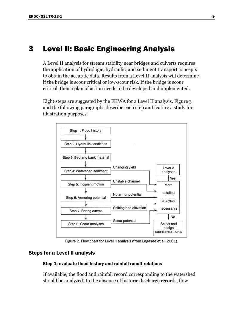
3 Level II: Basic Engineering Analysis
A Level II analysis for stream stability near bridges and culverts requires the application of hydrologic, hydraulic, and sediment transport concepts to obtain the accurate data. Results from a Level II analysis will determine if the bridge is scour critical or low-scour risk. If the bridge is scour critical, then a plan of action needs to be developed and implemented.
Eight steps are suggested by the FHWA for a Level II analysis. Figure 3 and the following paragraphs describe each step and feature a study for illustration purposes.
Figure 2. Flow chart for Level II analysis (from Lagasee et al. 2001).
Steps for a Level II analysis
Step 1: evaluate flood history and rainfall runoff relations
If available, the flood and rainfall record corresponding to the watershed should be analyzed. In the absence of historic discharge records, flow

ERDC/GSL TR-13-1 10
hydrographs must be produced by using empirical equations relating physical characteristics of the drainage area and discharge.
Step 2: evaluate hydraulic conditions
Flow velocity, depths, and geometric characteristics of the main channel and floodplain are basic hydraulic information necessary for a Level II stream stability analysis. In some cases, hydraulic information is available from local government agencies, flood insurance studies, or channel improvement projects. However, there are many cases in which field surveys and field reconnaissance studies are needed because no historical or hydraulic data have been recorded. Almost always, water surface profiles are required and computer models are used for this purpose. Typically, the data are analyzed by a computer program that provides results of scour estimation relations for the computation of potential scour depths.
Step 3: analyze bed and bank material
A detailed description of the bed and bank material and soil gradation curves from bed and bank soil samples should be gathered. Soil classification and specific weight also should be requested.
Step 4: evaluate watershed sediment yield
Quantification of watershed sediment yield and stability is important when the watershed has been subjected to significant disturbances. Shield’s Diagram is a commonly used criterion for incipient motion conditions.
Step 5: evaluate armoring potential
An armor layer is one of coarser sediment formed at the surface of the channel bed. As the sediment movement continues, an aggradation problem can be caused by the increase or decrease of land surface erosion. Further-more, sediment movement causes a reduction in the discharge capacity, increasing flood stages, and a reduction in the sediment yield, providing additional energy into the stream that causes degradation and head cutting. A well-known estimate for sediment yield is the US Department of Agriculture’s Universal Soil Loss Equation. This type of analysis is

ERDC/GSL TR-13-1 11
important when significant changes are occurring in the watershed or when unusual rates of aggradation or degradation are observed at the site.
Step 6: analyze incipient motion
Incipient motion analysis refers to the estimation of the critical condition where hydrodynamic forces act on one grain of sediment, reaching a limiting value so a slight increase will move the grain. The hydrodynamic forces, lift, and drag are equal to the resisting forces in the grain. This calculation provides an estimate of the magnitude of the flood that could disrupt the channel.
Step 7: evaluate rating curves shifts
Changes in the rating curve might indicate changes in the watershed conditions causing channel degradation or aggradation. To be conclusive, this analysis requires a long record of consistent discharge data and is possible when stream data is available.
Step 8: evaluate scour conditions
At this point, include detailed scour calculations as part of a numerical model. The use of such models provides different scenarios for which scour evaluations are possible.

ERDC/GSL TR-13-1 12
4 National Bridge Inspection Program Codes for Bridge Scour Assessment
The National Bridge Inspection Standards Regulation (NBIS) requires inspection at two-year intervals of all bridges in the National Bridge Inventory (NBI). FHWA specifies the field data that should be collected and reported for the bridges and channels. The following codes are related specifically to hydraulic and scour conditions.
Item 60: substructure
This item requires inspection of the physical conditions of piers, abutments, piles, fenders, and footings. Visible signs of distress (e.g., cracking, section loss, settlement, misalignment, scour, collision damage, and corrosion) should be reported.
Item 61: channel and channel protection
This item refers to physical conditions associated with the flow through the bridge. Stream stability, channel conditions, riprap, slope protection, and stream control devices also are included. Debris should be noted on the inspection but not included in the rating.
Item 71: waterway adequacy
This item refers to passage of flow through the bridge. It contains descriptions for functional classification (e.g., Freeways, Major Collectors, and Minor Collectors). Overtopping frequency is included, if available.
Item 92: critical feature inspection
This item denotes critical features that need special inspections. The time interval could change from inspection to inspection, depending on the bridge’s condition.
Item 93: critical inspection date
This item requires that, for each critical feature inspection in Item 92, the month and year of the last inspection be recorded.

ERDC/GSL TR-13-1 13
Item 113: scour-critical bridges
This item considers all possible bridge situations in terms of scour risk, vulnerability, and protection. It features 13 codes, from “unknown foundation” and “no evaluation made” to “bridge is scour critical.” A plan of action is required for each scour-critical bridge.
Items and codes must be completed as part of the requirements of the NBIS for bridge scour evaluation. They are included in the proposed Level I Scour Evaluation form of Appendices A, B, and C.

ERDC/GSL TR-13-1 14
5 Conclusion and Recommendations
All bridges on the US Army Installations inventory that cross waterways are to be evaluated for vulnerability to scour and stream instability, in accordance with the NBIS. The evaluation, analysis, and prediction of scour at bridges are complex issues due to the variability of conditions encountered at each site. All existing analyses and design methodologies must account for variability of site conditions and potential interaction of non-constant components of scour. Researchers and engineers have agreed that field data is necessary to validate all methodologies and analyses for each particular case and to ensure the reliability of the design.
In accordance with the NBIS and FHWA, a qualitative field data record and quantitative engineering analysis overview is proposed herein to account for bridges at risk for scour and channel instability. To minimize the risk to the public, monitor the structure and recommend cost effective strategies for repairing or replacing bridges.

ERDC/GSL TR-13-1 15
References
DeWall, P., S. Blanchard, and M. Gieseke. 2009. Bridge scour evaluation procedure for Minnesota bridges. St. Paul, MN: Minnesota Department of Transportation.
Johnson, P. A., G. L. Gleason, and R. D. Hey. 1999. Rapid assessment of channel stability in vicinity of road crossing. Journal of Hydraulic Engineering 125(6):645-651.
Lagasse, P. F., J. D. Schall, and E. V Richardson. 2001. Hydraulic engineering circular No. 20: Stream stability at highway structures. Fort Collins, CO: US Department of Transportation, Federal Highway Administration.
Mays, L. W. 2005. Water resources engineering. New York: John Wiley & Sons.
Richardson, E. V., and S. R. Davis. 2001. Hydraulic engineering circular No. 18: Evaluating scour at bridges. Washington DC: US Department of Transportation, Federal Highway Administration.

ERDC/GSL TR-13-1 16
Appendix A: Geomorphology Form

ERDC/GSL TR-13-1 17
Geomorphology (section does not need to be filled out as frequently)
Channel boundaries (geologic map, aerial photo)
Alluvial
Semi-alluvial
Non-alluvial
Floodplains (aerial photo)
Small (2x channel width)
Narrow (2-10x channel width)
Wide (>10x channel width)
Valley setting
No valley
Low relief (<30m)
Moderate (30-300 m)
High relief (>300 m)
River sinuosity (aerial photo)
Straight (1-1.05)
Sinuous (1.06-1.25)
Meandering (1.25-2)
Highly Meandering (>2)
Handmade
Flow habit Ephemeral Intermittent Perennial flashy
Perennial Tidal
Stream size (channel width)
Small (<100ft) Medium (100-500 ft)
Large (>500 ft)
Stream width Equiwidth
Wider at bends
Random

ERDC/GSL TR-13-1 18
Narrow point bars
Wider point bars
Irregular points
Natural levees Little or none
Concave
Well developed
Apparent incision Not incised
Probably incised
Braided stream Not braided (<5%)
Locally braided (5-35%)
Generally braided (>35%)
Anabranched stream
Not anabranched (<5%)
Locally anabranched (5-35%)
Generally anabranched (>35%)
In-stream mining or dredging
Yes No Remarks:
Head cuts or nickpoints
Yes No Remarks:
Diversion Yes No Remarks:
Channel modifications
Yes No Remarks:
Dams or reservoirs
Yes No Remarks:
Sediment transport (main channel)
1. Vegetation in the main channel _____ Yes _____ No

ERDC/GSL TR-13-1 19
2. Bed material below armor layer
Coarse (>1 mm) Fine (<1mm) Mixed
3. Stream gradient Mild Steep Unknown
4. Bed materials larger than biggest transported by flow
Yes No Unknown
5. Armored bed (coarse particles shield bed surface)
Yes No Unknown
If the answer to questions 1, 2, 3, and 4 are “yes,” “coarse,” and “mild,” CLEAR WATER scour is predominant.
6. Clear water scour Live bed scour
Other Considerations
7. Tidal influence Yes No Possible
8. Tributaries Upstream Downstream No factor
9. Distance to confluence with next stream/water body (meters)(range finder):
10. Watershed land use (aerial photo)
Agricultural Forested Urban Swamp

ERDC/GSL TR-13-1 20
Appendix B: Glossary
River- and scour-related terms
Alluvial island
A landform elevated above and surrounded by channel branches that persist sufficiently long for trees to be established. Alluvial islands occur in streams of all sizes and types. Their locations, shapes, and geomorphic expressions suggest that islands originate from many different mechanisms such as avulsion of floodplains, fragmentation of terraces, sedimentation and avulsion at mouths of tributaries, construction behind flow obstructions, and deposition in areas of flow expansion.
Aggradation
A progressive rising of the channel bed due to sediment deposition. It is an indicator that changes in discharge and sediment load are taking place.
Bank
The sides of the river between which the flow is confined. It also can be called a streambank.
Bank line
The boundary of the river’s main channel.
Bar
The accumulation of sediment along the bank. In straight and meandering channels, the bars are present as alternate bars following the river sinuosity.
Bend
The curve of a river, similar to the curve of a pipe.

ERDC/GSL TR-13-1 21
Braided channel
Created when a stream channel is divided into several smaller ones by the accumulation of in-channel deposits and when the channel width is greater than its depth.
Figure C1. Plan view of a braided channel form (Mount 1995).
Channel
The bed and banks that confine the surface flow of a natural or manmade stream.
Debris
Material transported by the stream (e.g., trash or logs) that can lodge against the bridge.
Cross section
A diagram or drawing cut across a channel that illustrates the banks, bed, and water surface.
Degradation
A progressive lowering of the channel bed due to scour (the opposite of aggradation). However, like aggradation, it is an indicator that changes in discharge and sediment load are taking place.

ERDC/GSL TR-13-1 22
Depth of scour
Means the vertical distance of the streambed has been lowered by scour, with respect to a reference elevation.
Discharge
The volume of water per unit of time passing a given point (vertical plane).
Erosion
The displacement of soil particles on the land surface due to water or wind action.
Fine sediment load
The load of sediment composed of particles sizes finer than those presented in the bed (also called washload).
General scour
Scour in a channel or on floodplain that is not localized at a pier, abutment, or other obstruction to flow.
Lateral erosion
Process by which the removal of material has principally a lateral component in contrast with scour.
Local scour
Scour localized at a pier, abutment, or other obstruction to flow.
Meandering channel
Has alternating bends, giving an S-shaped appearance. It also consists of a series of deep pools in the bends and shallow crossings in the short straight reach of a channel between the bends.
Multiple channels
Channel divisions around alluvial islands.

ERDC/GSL TR-13-1 23
Point bar
Alluvial deposits of sand or gravel lacking permanent vegetal cover; located at the inside of a meander loop.
Scour
Erosion due to flowing water that has a dominant vertical component.
Sediment load
The amount of sediment being moved by a stream.
Sedimentation
The deposition or settling of soil particles suspended in water.
Seepage
The slow movement of water through small cracks and pores of the bank material.
Slope
The difference in topographic elevation of two points on the thalweg divided by the thalweg length between the two points, expressed as a ratio.
Sinuosity
The ratio of the thalweg length to the down-valley distance. If the sinuosity is less than 1.5, the channel is considered straight. If the sinuosity is greater than 1.5, the channel is considered meandering.
Straight channel
Channels do not follow a sinuous course and have generally straight banks. For relatively long distances, the thalweg tends to be sinuous due to the instability of the alternate bars.
Stream
A body of water that might range from a large river to a small channel.

ERDC/GSL TR-13-1 24
Suspended sediment
Sediment that remains suspended in water for a considerable period without contact with the bottom.
Thalweg
Trace of the path of greatest depth along the channel.
Upper bank
The portion of streambank that is at an elevation greater than the average water level of the stream.
Bridge structure terms
Abutment
The connection between the end of the bridge and the earth. It provides support for the end sections of the bridge (roadway approach to the bridge), which transfer loads from the superstructure to the foundation and provide lateral support for the embankment. It usually is classified as spill-through or vertical. There are two basic types of abutments: open end and closed end. Open-end abutments are located near the top of the approaching roadway embankment. Closed-end abutments retain the soil so an embankment does not exist under the bridge.
Approach roadway
The portion of the road immediately adjacent to the bridge, including the approaching guardrail (approach rail).
Abutment type
The two primary types are integral and nonintegral. Integral abutments are rigidly connected to the bridge beams and deck with no expansion joint. The nonintegral bridge abutment is separated from the bridge beams and deck by a mechanical joint that allows thermal expansion and contraction of the bridge.

ERDC/GSL TR-13-1 25
Back wall
A retaining wall for the soil beyond the end of the bridge. It also can be a support for the extreme end of the bridge deck and the approach slab backwater.
Beam
A linear structural member designed to span from one support to another.
Beam bridge
Consists of a horizontal slab supported at each end. It is a simple type of bridge, composed of horizontal beams supported by vertical posts.
Bent
A substructure unit made of two or more columns or column-like members connected at their top-most ends by a cap, strut, or other member that holds them in their correct positions.
Bridge opening
The cross-sectional area beneath a bridge that conveys water.
Bridge waterway
The area of a bridge opening available for flow, as measured below a specified stage and normal to the principal direction of flow.
Deck
The traffic-carrying surface (top surface of a bridge) added to the superstructure.
Embankment
Earth or rock (also called a bank) built above the natural ground surface to carry a road or to prevent water from passing beyond desirable limits. All dams are types of embankments.
Grout
A thin mortar used to fill cracks and crevices in masonry.

ERDC/GSL TR-13-1 26
Riprap
Gabions, stones, blocks of concrete, or other protective covering material of the sort that is deposited in rivers and streambeds and on banks, lake, tidal, or other shores to prevent erosion and scour by water flow, wave, or other movement.
Rubble
Irregularly shaped pieces of stone in the undressed condition, obtained from a quarry and varying in size.
Seawall
A hard defense constructed on the inland part of a coast to reduce the effects of strong waves and to protect the area around a town or harbor from erosion.
Spread footing
A footing that is wide and usually made of reinforced concrete; ideally suited for foundation material with moderate bearing capacity.
Superstructure of the bridge
The horizontal platform that spans the space between columns.
Wingwall
The retaining wall extension of an abutment intended to restrain and hold in place the side slope material of an approach roadway embankment. The retaining wall extension extends outward from the back wall along the riverbank to retain fill dirt for the bridge approaches.

REPORT DOCUMENTATION PAGE Form Approved
OMB No. 0704-0188 Public reporting burden for this collection of information is estimated to average 1 hour per response, including the time for reviewing instructions, searching existing data sources, gathering and maintaining the data needed, and completing and reviewing this collection of information. Send comments regarding this burden estimate or any other aspect of this collection of information, including suggestions for reducing this burden to Department of Defense, Washington Headquarters Services, Directorate for Information Operations and Reports (0704-0188), 1215 Jefferson Davis Highway, Suite 1204, Arlington, VA 22202-4302. Respondents should be aware that notwithstanding any other provision of law, no person shall be subject to any penalty for failing to comply with a collection of information if it does not display a currently valid OMB control number. PLEASE DO NOT RETURN YOUR FORM TO THE ABOVE ADDRESS.
1. REPORT DATE (DD-MM-YYYY) January 2013
2. REPORT TYPE Final
3. DATES COVERED (From - To)
4. TITLE AND SUBTITLE
Methodology of Scour Evaluation at US Army Installation Bridges: A Proposed Evaluation for Scour Risk and Channel Instability
5a. CONTRACT NUMBER
5b. GRANT NUMBER
5c. PROGRAM ELEMENT NUMBER
6. AUTHOR(S) Deborah Suazo-Davila, Walter Silva-Araya, and Jorge Rivera-Santos
5d. PROJECT NUMBER
5e. TASK NUMBER
5f. WORK UNIT NUMBER
7. PERFORMING ORGANIZATION NAME(S) AND ADDRESS(ES) 8. PERFORMING ORGANIZATION REPORT NUMBER
US Army Engineer Research and Development Center Geotechnical and Structures Laboratory 3909 Hall Ferry Road, Vicksburg, MS 39180-6199 Puerto Rico Water Resources and Environmental Research Institute University of Puerto Rico at Mayagüez Stefani Building No. 318, Route No.2 Mayagüez, PR 00681-9040
ERDC/GSL TR-13-1
9. SPONSORING / MONITORING AGENCY NAME(S) AND ADDRESS(ES) 10. SPONSOR/MONITOR’S ACRONYM(S)
Headquarters, Installation Management Command San Antonio, TX 78233
HQ-IMCOM 11. SPONSOR/MONITOR’S REPORT NUMBER(S)
12. DISTRIBUTION / AVAILABILITY STATEMENT
Approved for public release; distribution unlimited.
13. SUPPLEMENTARY NOTES
14. ABSTRACT At the end of the past decade, channel stability and scour risk considerations were not part of stream crossing design for roads. According to the National Bridge Inspection Standards (NBIS), all bridges crossing waterways are to be assessed for vulnerability to scour risk and stream instability. General guidelines for scour risk and channel instability are contained within Hydraulic Engineering Circular (HEC) Nos. 18, 20, and 23, published by the Federal Highway Administration (FHWA). In accordance with the NBIS and FHWA, the US Army Corps of Engineers (USACE) has developed a scour evaluation program to account for those bridge conditions caused by scour risk and channel instability.
The purpose of this document is to present an overview of and the guidelines for identify bridges on U.S. Army Installations inventory that are at risk of scour and subject to channel instability.
Techniques based on hydrology, geomorphology, and bridge design have been studied for use in channel classification and reconnaissance. Field assessment methods also have been investigated for use in identifying potential channel instability. Qualitative evaluation and quantitative engineering analysis also are presented herein, in order to propose a complete scour evaluation form based on channel stability and rating procedures, as well as basic bridge, culvert, and abutment dimensions. This form is used to obtain general data for determining which bridges might be vulnerable to scour. The scour evaluation form is recommended as an effort in minimizing the risk to the public, monitoring the structure, and recommending repair or replacement strategies.
15. SUBJECT TERMS
Channel Erosion
Bridge Analysis Scour
16. SECURITY CLASSIFICATION OF: 17. LIMITATION OF ABSTRACT
18. NUMBER OF PAGES
19a. NAME OF RESPONSIBLE PERSON
a. REPORT
UNCLASSIFIED
b. ABSTRACT
UNCLASSIFIED
c. THIS PAGE
UNCLASSIFIED 34 19b. TELEPHONE NUMBER (include area code)
Standard Form 298 (Rev. 8-98)Prescribed by ANSI Std. 239.18


