![January 2017 Version 2.1 Coop Negative List for Textile ... und... · January 2017 Version 2.1 Limit Test Method Limit [µg/L] Test Method Limit [mg/kg] Test Method Input Chemicals](https://static.fdocuments.net/doc/165x107/5c86cdca09d3f2815e8cbbf6/january-2017-version-21-coop-negative-list-for-textile-und-january-2017.jpg)
METHOD OF TESTS FOR LIQUID LIMIT, PLASTIC LIMIT, AND ......METHOD OF TESTS FOR LIQUID LIMIT, PLASTIC...
16
-1- California Test 204 June 2010 DEPARTMENT OF TRANSPORTATION DIVISION OF ENGINEERING SERVICES Transportation Laboratory 5900 Folsom Blvd. Sacramento, California 95819-4612 METHOD OF TESTS FOR LIQUID LIMIT, PLASTIC LIMIT, AND PLASTICITY INDEX OF SOILS A. SCOPE This test method describes the procedures for determining the liquid limit, plastic limit, and plasticity index of a soil including cement or lime treated soils. B. REFERENCES: California Test 226 – Determination of moisture content by Oven Drying AASHTO T 87 – Dry Preparation of Disturbed Soil and Soil Aggregate Samples for Test AASHTO T 89 – Determining the Liquid Limit of Soils AASHTO T 90 – Determining the Plastic Limit and Plasticity Index of Soils C. APPARATUS 1. Dish: porcelain evaporating dish or similar mixing dish approximately 115 mm in diameter. 2. Spatula: spatula or pill knife having a blade about 75 mm to 100 mm in length and about 20 mm in width. 3. Containers: suitable containers made of material resistant to corrosion and not subject to change in weight or disintegration on repeated heating and cooling. Containers must have close-fitting lids to prevent loss of moisture from samples before initial weight determination and to prevent absorption of moisture from the atmosphere following drying and before final weight determination. One container is needed for each moisture content determination. 4. Balance: the balance must have sufficient capacity, be accurate to 0.02 g or 0.1 %, and readable and sensitive to 0.01 g. 5. Oven: a thermostatically controlled drying oven capable of maintaining temperatures of 140ºF ± 9ºF and 230ºF ± 9ºF. Additional Liquid Limit equipment: 6. Liquid Limit Device: a. Manually Operated: a device consisting of a brass dish and carriage, constructed according to the plan and dimensions shown in Figure 1. b. Mechanically Operated: a motorized device equipped to produce the rise and rate of shocks to a brass cup in accordance with Part I Sections 1.B.2.c and 1.E of this test method. The cup and the critical dimensions of the device must conform to those shown in Figure 1. STATE OF CALIFORNIA—BUSINESS, TRANSPORTATION AND HOUSING AGENCY
Transcript of METHOD OF TESTS FOR LIQUID LIMIT, PLASTIC LIMIT, AND ......METHOD OF TESTS FOR LIQUID LIMIT, PLASTIC...

-1-
California Test 204 June 2010
DEPARTMENT OF TRANSPORTATIONDIVISION OF ENGINEERING SERVICES Transportation Laboratory 5900 Folsom Blvd. Sacramento, California 95819-4612
METHOD OF TESTS FOR LIQUID LIMIT, PLASTIC LIMIT, AND PLASTICITY INDEX OF SOILS
A. SCOPE
This test method describes the procedures for determining the liquid limit, plastic limit, and plasticity index of a soil including cement or lime treated soils.
B. REFERENCES:
California Test 226 – Determination of moisture content by Oven Drying AASHTO T 87 – Dry Preparation of Disturbed Soil and Soil Aggregate Samples for Test AASHTO T 89 – Determining the Liquid Limit of Soils AASHTO T 90 – Determining the Plastic Limit and Plasticity Index of Soils
C. APPARATUS
1. Dish: porcelain evaporating dish or similar mixing dish approximately 115 mm indiameter.
2. Spatula: spatula or pill knife having a blade about 75 mm to 100 mm in lengthand about 20 mm in width.
3. Containers: suitable containers made of material resistant to corrosion and notsubject to change in weight or disintegration on repeated heating and cooling.Containers must have close-fitting lids to prevent loss of moisture from samplesbefore initial weight determination and to prevent absorption of moisture fromthe atmosphere following drying and before final weight determination. Onecontainer is needed for each moisture content determination.
4. Balance: the balance must have sufficient capacity, be accurate to 0.02 g or0.1 %, and readable and sensitive to 0.01 g.
5. Oven: a thermostatically controlled drying oven capable of maintainingtemperatures of 140ºF ± 9ºF and 230ºF ± 9ºF.
Additional Liquid Limit equipment:
6. Liquid Limit Device:
a. Manually Operated: a device consisting of a brass dish and carriage,constructed according to the plan and dimensions shown in Figure 1.
b. Mechanically Operated: a motorized device equipped to produce the riseand rate of shocks to a brass cup in accordance with Part I Sections1.B.2.c and 1.E of this test method. The cup and the critical dimensionsof the device must conform to those shown in Figure 1.
STATE OF CALIFORNIA—BUSINESS, TRANSPORTATION AND HOUSING AGENCY

California Test 204 June 2010
-2-
c. The device must give the same liquid limit values as obtained with the manually operated device.
NOTE: The base of the liquid limit device should have a resilience of at least
80 % and not more than 90 % when determined in accordance with the procedure given in the Appendix. The base resilience must be measured and recorded on the calibration documentation annually.
7. Curved Grooving Tool: a grooving tool conforming to the critical dimensions
shown in Figure 1. The gauge need not be part of the tool.
NOTE: A flat grooving tool should not be used. There are some data that indicate that the liquid limit is slightly increased when a flat tool is used.
8. Gauge: a gauge, whether attached to the grooving tool or separate, conforming to
the critical dimension “d” shown in Figure 1 of this method, and may be, if separate, a metal bar 10.0 mm ± 0.2 mm thick and approximately 50 mm long.
Additional Plastic Limit equipment:
9. Surface for Rolling: a ground glass plate or piece of smooth, unglazed paper on
which to roll the sample. 10. Plastic Limit Rolling Device (optional): a device made of acrylic conforming to the
dimensions shown in Figure 2. 11. Paper for Rolling Device: unglazed paper that does not add foreign matter (fibers,
paper fragments, etc.) to the soil during the rolling process. Attach paper to the top and bottom plates of the device either by a spray-on adhesive or by a self- adhesive backing.
NOTE: Remove the adhesive that remains on the plastic limit rolling device after testing.
Repeated testing without removal will result in a buildup of the residual adhesive and a decreased soil thread diameter.
D. SAMPLE PREPARATION
1. Quarter out approximately 500 g of the passing No. 4 portion from the soil to be
tested.
2. If the sample is moist, dry thoroughly in air or dry with artificial heat at a temperature of 140ºF ± 9ºF.
NOTE: Be sure that all fines are separated from sand grains and that all clay
lumps are broken apart. Do not dry samples in temperatures exceeding 140°F, as it will lower liquid and plastic limits of some soils. Organic colloids are partially destroyed by excessive heat and some colloidal grains may be baked together.
3. Sieve the sample over the No. 40 sieve. Use a pulverizing apparatus to grind the
portion retained on the No. 40 sieve. Grind in such a manner as to break up the aggregations of soil particles without fracturing the individual grains.

California Test 204 June 2010
-3-
Repeat this sieving and grinding of the portion retained on the No. 40 sieve until vigorous kneading of a portion of the material retained on the No. 40 sieve between the palm of one hand and the thumb of the other produces no further separation of finer material.
4. Place all of the passing No. 40 soil obtained from Steps 1 through 3 in a properly
identified container. This is the portion of the sample that will be used in determining the liquid and plastic limits. Discard the portion retained on the No. 40 sieve.
PART I LIQUID LIMIT
1.A. DEFINITION The liquid limit (LL) of a soil is the water content at which the soil passes from a plastic state to a liquid state. 1.B. METHOD A
1. PREPARATION OF SAMPLE Take a sample with a weight of about 100 g from the thoroughly mixed portion of the material passing the No. 40 sieve. 2. PROCEDURE USING THE CURVED GROOVING TOOL
a. Place the soil sample in the mixing dish and thoroughly mix with 15 mL
to 20 mL of distilled or deionized water by alternately and repeatedly stirring, kneading and chopping with a spatula. Make further additions of water in increments of 1 mL to 3 mL. Thoroughly mix each increment of water with the soil as previously described before adding another increment of water. Once testing has begun, do not add additional dry soil to the moistened soil. Do not use the cup of the liquid limit device for mixing soil and water. If too much moisture has been added to the sample, discard the sample or mix and knead until natural evaporation lowers the closure point into an acceptable range.
NOTE: Some soils are slow to absorb water and it is possible to add the
increments of water so fast that a false liquid limit value is obtained. This can be avoided if more mixing and/or time is allowed. Tap water may be used for routine testing if comparative tests indicate no differences in results between using tap water and distilled or deionized water. However, referee (Part I Section 1.D) or disputed tests must be performed using distilled or deionized water.
b. When sufficient water has been thoroughly mixed with the soil to form a
uniform mass of stiff consistency, place a sufficient quantity of this mixture in the cup above the spot where the cup rests on the base.

California Test 204 June 2010
-4-
Squeeze and spread the moistened soil with the spatula to level and at the same time trim to a depth of 10 mm at the point of maximum thickness. Use as few strokes of the spatula as possible. Take care to prevent the entrapment of air bubbles within the mass. Return the excess soil to the mixing dish and cover to retain the moisture in the sample. Divide the soil in the cup of the device using a firm stroke of the grooving tool along the diameter through the centerline of the cam follower so that a clean sharp groove of the proper dimensions is formed. To avoid tearing of the sides of the groove or slipping of the soil cake on the cup, up to 6 strokes from front to back or from back to front counting as 1 stroke are permitted. The depth of the groove should be increased with each stroke and only the last stroke should scrape the bottom of the cup.
c. Lift and drop the cup containing the sample prepared in accordance with
Part I Section 1.B.2 of this test method by turning the crank at the rate of approximately 2 revolutions per second until the 2 sides of the sample come in contact at the bottom of the groove along a distance of about 13 mm. Record the number of shocks required to close the groove this distance. Do not hold the base of the liquid limit device with the free hand while turning the crank.
NOTE: Some soils tend to slide on the surface of the cup instead of
flowing. If this occurs, add more water to the sample and remix, then repeat Part I Section 1.B.2.b and c. If the soil continues to slide at fewer blows than 25, the test is not applicable and a note must be made that the liquid limit could not be determined.
d. Remove a slice of soil approximately the width of the spatula, extending
from edge to edge of the soil cake at right angles to the groove and including that portion of the groove in which the soil flowed together. Place it in a suitable container. Dry the soil in the container in accordance with California Test 226 to determine the moisture content. Record the results.
e. Transfer the soil remaining in the cup to the mixing dish. Wash and dry
the cup and grooving tool in preparation for the next trial. f. Repeat the foregoing operations for at least two additional portions of the
sample to which sufficient water has been added to bring the soil to a more fluid condition. The object of this procedure is to obtain samples of such consistency that at least one determination will be made in each of the following ranges of shocks: 25 to 35, 20 to 30, 15 to 25, so the range in the 3 determinations is at least 10 shocks.
3. CALCULATION Express the water content of the soil as the moisture content in percentage of the weight of the oven-dried soil and calculate as follows:
100
soildried ovenof Weight
waterof Weight Moisture Percentage
Calculate the percentage of moisture to the nearest whole percent.

California Test 204 June 2010
-5-
4. PREPARATION OF FLOW CURVE Plot a “Flow Curve” representing the relation between moisture content and corresponding number of shocks on a semi-logarithmic graph with the moisture contents as abscissa on the arithmetical scale and the number of shocks as ordinates on the logarithmic scale. The flow curve is a straight line drawn as nearly as possible through the 3 or more plotted points. 5. LIQUID LIMIT The liquid limit of the soil is the moisture content corresponding to the intersection of the flow curve with the 25 shock ordinate. Report this value to the nearest whole number.
1.C. METHOD B
1. PREPARATION OF SAMPLE Take a sample with a weight of about 50 g from the thoroughly mixed portion of the material passing the No. 40 sieve. 2. PROCEDURE
a. Using the same procedure in accordance with Part I Sections 1.B.2.a. through 1.B.2.e. of this test method except that the initial amount of water to be added in accordance with Part I Section 1.B.2.a. of this test method must be approximately 8 to 10 mL and the moisture sample taken in accordance with Part I Section 1.B.2.d. of this test method must be taken only for the accepted trial.
b. For accuracy equal to that obtained by the standard 3-point method,
restrict the accepted number of blows for groove closure to between22 and 28 blows. After obtaining a preliminary closure in the acceptableblow range, immediately return the soil remaining in the cup to the mixing dish and, without adding any additional water, repeat in accordance with Part I Sections 1.B.2.a through c. of this test method. If the second closure occurs in the acceptable range (22 to 28 inclusive) and the second closure is within 2 blows of the first closure, secure a water content specimen in accordance with Part I Section 1.B.2.d. of this test method.
d. Groove closures between 15 and 40 blows may be accepted if variations
of ± 5 % of the true liquid limit are tolerable.
3. CALCULATION Calculate the water content of the soil at the time of the accepted closure in accordance with Part I Section 1.B.3. of this test method. 4. LIQUID LIMIT
Determine the liquid limit by one of the following methods:

California Test 204 June 2010
-6-
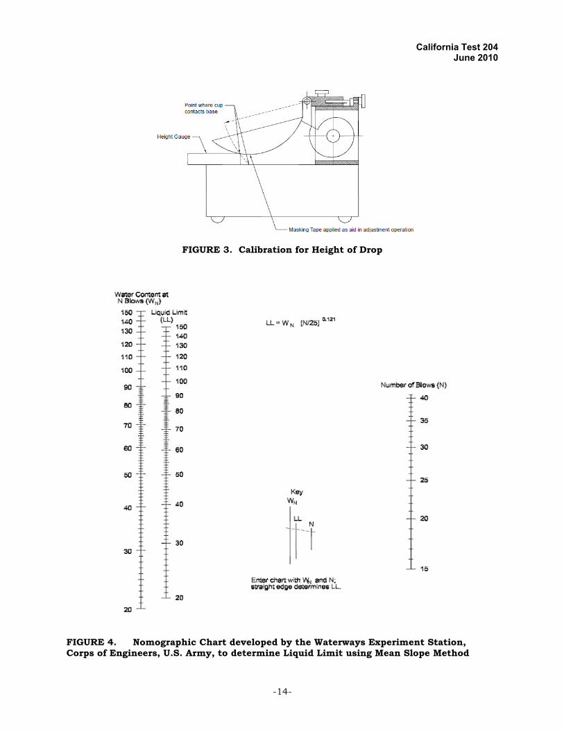
a. The nomograph (Figure 4). The key in Figure 4 illustrates the use of the nomograph (mean slope).
b. The correction factor method, TABLE 1, uses the moisture content of the
liquid limit sample multiplied by a factor (k) of the second closure blow count. Figure 5 was developed for the calculation of the liquid limit.
1210
25
.
NN
W LL
or
NWk LL
Where: N = number of blows causing closure of the groove at water content,
LL = Liquid Limit corrected for closure at 25 blows, WN = water content, andk = factor given in Table 1.
c. Or by any other method of calculation that produces equally accurate
liquid limit values. Use the standard 3-point method as a referee test to settle all controversies.
1.D. CHECK OR REFEREE TESTS Use Method A in making check or referee tests. The results of liquid limit tests are influenced by:
1. The time required to make the test. 2. The moisture content at which the test is begun. 3. The addition of dry soil to the seasoned sample.
Therefore, in making the liquid limit test for check or referee purposes, the following time schedule must be used:
1. Mixing of soil with water – 5 to 10 min, the longer period being used for the more
plastic soils.
2. Seasoning in the humidifier – 30 min. 3. Remixing before placing in the brass cup – add 1 mL of water and mix for 1 min. 4. Placing in the brass cup and testing – 3 min. 5. Adding water and remixing – 3 min.
Do not record any trial requiring more than 35 blows or fewer than 15 blows. Do not add dried soil to the moistened soil being tested.

California Test 204 June 2010
-7-
1.E. ADJUSTMENT OF LIQUID LIMIT DEVICE Inspect the liquid limit device to determine that:
1. The device is in good working order. 2. The pin connecting the cup is not worn sufficiently to permit side play. Replace
the pin if side play is detected. 3. The screws connecting the cup to the hanger arm are tight. 4. The points of contact on the cup and base do not exceed 13 mm in diameter.
NOTE: A base which is excessively worn may be refinished as long as the thickness does not exceed the tolerance shown in Figure 1 by more than –2.5 mm and the distance between the cup at the cam follower and the base is maintained within the tolerances specified in Figure 1.
5. No point on the rim of the cup is worn to less than half the original thickness. 6. A groove has not been worn in the cup through long usage.
NOTE: Although a slight groove in the center of the cup may be noticeable, it is not objectionable unless the groove becomes pronounced before other signs of wear appear, at which time the cup should be considered excessively worn. Excessively worn cups must be replaced.
Inspect the grooving tool to determine that the critical dimensions are as shown in Figure 1.
Be sure that the liquid limit device is in proper adjustment by frequently checking the drop of the brass cup. Adjust the height of drop of the cup so that the point on the cup that comes in contact with the base rises to a height of 10 mm ± 0.2 mm. See Figure 3 for proper location of the gauge relative to the cup during adjustment. NOTE: A convenient procedure for adjusting the height of drop is as follows:
1. Place a piece of masking tape across the outside bottom of the cup parallel with the axis
of the cup hanger pivot. (The edge of the tape away from the cup hanger should bisect the spot on the cup that contacts the base. For new cups, placing a piece of carbon paper on the base and allowing the cup to drop several times will mark the contact spot.)
2. Attach the cup to the device and turn the crank until the cup is raised to its maximum
height. 3. Slide the height gauge under the cup from the front, and observe whether the gauge
contacts the cup or the tape (Figure 3). 4. If the tape and cup are both contacted, the height of drop is approximately correct. If
not, adjust the cup until simultaneous contact is made. 5. Check adjustment by turning the crank at 2 revolutions per second while holding the
gauge in position against the tape and cup. If a ringing or clicking sound is heard

California Test 204 June 2010
-8-
without the cup rising from the gauge, the adjustment is correct. If no ringing is heard or if the cup rises from the gauge, readjust the height of drop.
6. If the cup rocks on the gauge during this checking operation, the cam follower pivot is
excessively worn and the worn parts should be replaced. 7. Always remove tape after completion of adjustment operation. PART II PLASTIC LIMIT 2.A. DEFINITION The plastic limit (PL) of a soil is the lowest wate r content, as determined in accordance with the procedure in Part II Section 2.C, at which the soil becomes plastic.
2.B. PREPARATION OF SAMPLE
1. If the plastic limit only is required, take a quantity of soil with a weight of about 20 g from the thoroughly mixed portion of the material passing the No. 40 sieve. Place the soil in a mixing dish and thoroughly mix with distilled or deionized water until the mass becomes plastic enough to be easily shaped into a ball. Take a portion of this ball with a weight of about 8 g for the sample.
NOTE: Tap water may be used for routine testing if comparative tests indicate
no differences in results between using tap water and distilled or deionized water. However, referee or disputed tests (Part I Section 1.D) must be performed using distilled or deionized water.
2. If both the liquid and plastic limits are required, take a sample with a weight of
about 8 g from the thoroughly wet and mixed portion of the soil prepared in accordance with Part I.
2.C. TEST PROCEDURES
1. Select a 1.5 to 2.0 g portion from the 8 g soil ball prepared in accordance with Part II Section 2.B of this test method and form into an ellipsoidal mass.
2. Use one of the following methods to roll the soil mass into a 3 mm diameter
thread at a rate of 80 to 90 strokes per minute, counting a stroke as one complete motion of the hand forward and back to the starting position again.
a. Hand Rolling Method – Roll the weight between the palm or fingers and
the ground glass plate (or a piece of paper laying on a smooth horizontal surface) with just sufficient pressure to roll the weight into a thread of uniform diameter throughout its length.

California Test 204 June 2010
-9-
b. Further deform the thread on each stroke so that its diameter reaches 3 mm, taking no more than 2 min.
c. When the diameter of the soil thread becomes 3 mm, limit the length to
150 mm. The amount of hand or finger pressure required will vary greatly, according to the soil.
d. Fragile soils of low plasticity are best rolled under the outer edge of the
palm or at the base of the thumb. e. Plastic Limit Device Method (Alternate Procedure) – Place the soil mass
on the bottom plate. Place the top plate in contact with the soil mass. Simultaneously apply a slight downward force and back and forth motion to the top plate so that the plate comes in contact with the side rails within 2 min. During this rolling process, do not allow the soil thread to contact the side rails.
NOTE: In most cases, more than 1 soil mass (thread) can be rolled
simultaneously in the plastic limit rolling device.
3. When the diameter of the thread becomes 3 mm, break the thread into 6 or 8 pieces. Squeeze the pieces together between the thumbs and fingers of both hands into a uniform mass roughly ellipsoidal in shape and reroll. Continue this alternate rolling to a thread 3 mm in diameter, gathering together, kneading, and rerolling, until the thread crumbles under the pressure required for rolling and the soil can no longer be rolled into a thread. The crumbling may occur when the thread has a diameter greater than 3 mm. This will be considered a satisfactory end point, provided the solid has been previously rolled into a thread 3 mm in diameter. The crumbling will manifest itself differently with various types of soil. Some soils fall apart in numerous small aggregations of particles; others may form an outside tubular layer that starts splitting at both ends. The splitting progresses toward the middle, until finally, the thread falls apart in many small platy particles. Heavy clay soils require much pressure to deform the thread, particularly as they approach the plastic limit, and finally, the thread breaks into a series of barrel-shaped segments each about 6 to 10 mm in length. At no time attempt to produce failure at exactly 3 mm. diameter by allowing the thread to reach 3 mm, then reducing the rate of rolling or the hand pressure, or both, and continuing the rolling without further deformation until the thread falls apart. It is permissible, however, to reduce the total amount of deformation for feebly plastic soils by making the initial diameter of the ellipsoidal-shaped mass nearer to the required 3 mm final diameter.
4. Gather the portions of the crumbled soil together and place in a weighed
container. Immediately cover the container. 5. Repeat the operations in accordance with Part II Sections 2.C.1 through 4 of this
test method until the 8 g specimen is completely tested. Determine the moisture content of the soil in the containers in accordance with California Test 226. Record the results.

California Test 204 June 2010
-10-
2.D. CALCULATION OF PLASTIC LIMIT Calculate the plastic limit, expressed as the water content in percentage of the weight of the oven-dry soil, as follows:
100
soildry ovenof Weight
waterof Weight Limit Plastic
Report the plastic limit to the nearest whole number. PART III PLASTIC INDEX
3.A. DEFINITION The plasticity index (PI) of a soil is the numerical difference between its liquid limit (LL) and its plastic limit (PL). 3.B. CALCULATION Calculate the plasticity index of a soil as the difference between its liquid limit and its plastic limit, as follows:
PI = LL − PL
Report PI as non-plastic (NP) when:
1. The liquid limit or the plastic limit cannot be determined, or 2. The plastic limit is equal to or greater than the liquid limit.
PART IV TESTS OF CEMENT TREATED OR LIME TREATED SOILS 4.A. PROCEDURE Follow the procedures described in this test method with the following exceptions:
1. Determine percent of cement or lime to be added to the soil.
For field samples that contain 10 % or more aggregate retained on the No. 4 sieve, use the following example to determine the percent of cement or lime to add to the soil passing the No. 4 sieve.
Example: Two percent of cement is to be added in the field to an aggregate
graded 100 percent passing the ¾ in. sieve and 60 percent passing the No. 4 sieve.

California Test 204 June 2010
-11-
Let C = Percent cement required for the portion passing the No. 4 sieve.
Then 260100 C
60 C 200
C = 3.33 % 2. Add cement or lime to the material passing the No. 4 sieve prior to grinding and
sieving over the No. 40 sieve. 3. Add water and mix. Leave the mixed sample in an uncovered evaporating dish
in workroom for 24 hr.
4. Use spatula, plus hand operated mortar and pestle when necessary, and break up crust and soil-cement (or soil-lime) aggregations.
5. Add water, mix, and prepare the passing No. 40 sieve material in accordance
with Section D of this test method. Use sample preparation, testing, and calculation procedures in accordance with Parts I, II, and II of this test method.
E. PRECAUTIONS
1. In order to get good test reproducibility, it is necessary to use seasoned soil,
mold into ellipsoidal shape prior to rolling, exert the proper pressure during rolling, use the proper rate of rolling, use the proper length of soil thread, and prevent further moisture loss when the end point is reached.
2. Reproducibility of test results is very difficult unless the test is performed
exactly the same way each time. When training new operators, have them and an experienced operator conduct tests on duplicate samples. Do not use the new operator’s test results until they have mastered the test technique well enough to satisfactorily duplicate the test result of the experienced operator.
3. Conform exactly to the specified times for mixing, curing, and testing because
variations can cause erroneous test results. Some soils are slow to absorb water; therefore, it is possible to add the increments of water so fast that a false liquid limit value is obtained. Because this is particularly true when the liquid limit of a clay soil is obtained from one determination, it is of greatest importance that the soil and water be thoroughly and uniformly mixed and that at least two closures be observed to ensure that the accepted number of blows is truly characteristic of the soil under test.
4. Replace grooving tool tips that become worn. 5. Take moisture sample immediately after the soil flows together for a distance of
½ in. Keep edges of watch glasses free of soil particles so that a moisture proof seal will be obtained. Moisture samples are small and evaporation losses can cause erroneous results.

California Test 204 June 2010
-12-
F. HEALTH AND SAFETY It is the responsibility of the user of this test method to establish appropriate safety and health practices and determine the applicability of regulatory limitations prior to use. Prior to handling, testing or disposing of any materials, testers must be knowledgeable about safe laboratory practices, hazards and exposure, chemical procurement and storage, and personal protective apparel and equipment. Caltrans Laboratory Safety Manual is available at:
http://www.dot.ca.gov/hq/esc/ctms/pdf/lab_safety_manual.pdf
End of Text (California Test 204 contains 16 pages)

California Test 204 June 2010
-13-
FIGURE 1. Manual Liquid Limit Device
FIGURE 2. Plastic Limit Rolling Device
California Test 204 June 2010
-14-
FIGURE 3. Calibration for Height of Drop
FIGURE 4. Nomographic Chart developed by the Waterways Experiment Station,Corps of Engineers, U.S. Army, to determine Liquid Limit using Mean Slope Method

California Test 204 June 2010
-15-
TABLE 1.
Factors for Obtaining Liquid Limit from Water Content and Number of Blows Causing Closure of the Groove (from: AASHTO T89)
Number of Blows, N
Factor for Liquid Limit, k
22 0.98523 0.99024 0.99525 1.00026 1.00527 1.00928 1.014
FIGURE 5. Chart developed by Washington State Highway Department for the Calculation of the Liquid Limit

California Test 204 June 2010
-16-
APPENDIX
Resilience Test Measuring the Resilience of Liquid Limit Device Bases
A device for measuring the resilience of liquid limit device bases is shown in Figure X1.1 and Table X1.1. The device consists of a clear acrylic plastic tube and cap, an 8 mm diameter polished steel ball, and a small bar magnet. The cylinder may be cemented to the cap or threaded as shown. The small bar magnet is held in the recess of the cap, and the steel ball is fixed into the recess in the underside of the cap with the bar magnet. The cylinder is then turned upright and placed on the top surface of the base to be tested. Hold the tube lightly against the liquid limit device base with one hand, and release the ball by pulling the magnet out of the cap. Use the scale markings on the outside of the cylinder to determine the highest point reached by the bottom of the ball. Repeat the drop at least 3 times, placing the device in a different location for each drop. The average rebound of the steel ball, expressed as a percent of the total drop, equals the resilience of the liquid limit device base. Tests should be conducted at room temperature.
Figure X1.1. Resilience Tester
Table X1.1
Measurements for Resilience Tester
• Tube stands p!wnb.
Dimension Description Metric, mm A Diam. of Cap 38.0" B Diam. of Hole 9.0" C Depth of Hole 18.0" D Height of Cap 25.5" E Depth of Hole 8.0 F Length ofTube 250.0 G Wall Thickness 3.2" H O.D. of Tube 31.8'
Sc.rib,ed lines Uppe.r 90% 225.0 from bottom Lower SO% wo.o
These dimensions are not critical in the pufonwnce of the test.
Soibe Lines Completely Around Tube at 200 mm and 225 mm fltmBollDm
Cleer Plas!IG{8U<:h as ActyllC) cap and Tub&
I ------1
I ---t---
1
0
uJ
u..
I 0
I


![COMPARATIVE STUDIES OF CBR VALUE OF SOIL SAMPLE …[2] IS 2720 Part-5 “Metod of test for Soil-Determination of Liquid limit and Plastic limit”. [3] IS 2720 Part –8 “Method](https://static.fdocuments.net/doc/165x107/5e760ad3faec88301076bc03/comparative-studies-of-cbr-value-of-soil-sample-2-is-2720-part-5-aoemetod-of-test.jpg)