Methane to Syngas - Division on Earth and Life...
27
Methane to Syngas Jan J Lerou Jan Lerou Consulting, LLC March 7, 2016 The Changing Landscape of Hydrocarbon Feedstocks for Chemical Production Implications for Catalysis: A Workshop
Transcript of Methane to Syngas - Division on Earth and Life...
Methane to Syngas
Jan J Lerou
Jan Lerou Consulting, LLC
March 7, 2016
The Changing Landscape of Hydrocarbon Feedstocks for Chemical Production
Implications for Catalysis: A Workshop

Methane to syngas process technologies
Commercial technologies Steam reforming
Partial oxidation
Non-catalytic partial oxidation
Auto-thermal reforming
Catalytic partial oxidation
Almost commercial technology Short Contact Time – Catalytic Partial Oxidation
Oxygen Transfer Membranes – Praxair
Dry Reforming
Emerging Technologies Chemical Looping
Tri-reforming

Commercial Process Technologies

SMR Technology
Conventional
technology
Capacity: 20 million standard cubic
feet/day
Large Size:~30m x ~30m x ~30 m

SMR Technology Today
Source: Basini, Eni

SMR Technology
Limitations Carbon formation at low steam/carbon
High conversion requires high temperatures
Excess steam production
Cooling in waste heat boiler to avoid Boudouardcarbon formation
Low NOx levels required in stack
Challenges Lower the steam/carbon ratio
Low NOx burners
Material limitation in tube alloys
Reduce excess steam production by air preheat and pre-reforming

SMR Catalyst Technology
Supports:
α - and γ-Al2O3, MgO, MgAl2O4, SiO2, ZrO2, CeO2, TiO2
Active metals:
Mostly Ni - Ru, Rh, Pd, Ir, Pt
Zoneflow Technologies LLC CATACEL - JMAlantum

Partial Oxidation Technology
Source: Basini, Eni

POX Technology
Limitations
Possibility of utilizing a “low value” feedstock.
Reaction is exothermic (energy consumption is less)
Environmentally friendly in terms of exhaust gases:
little NOx production
Challenges
Oxidation step is highly exothermic, reducing the
energy content of the fuel
Cost of reaction materials are high
Soot can easily emerge in the non-catalytic POX
process

Auto-thermal reforming technology
Source: Basini, Eni

ATR Technology
Limitations
Cost of oxygen
Limitation in H2 pressure
Limitation in exit temperature
Requires waste heat boiler to avoid Boudouard carbon
formation
Challenges
Lower the steam/carbon ratio
Increase CH4 conversion by increasing temperature
Carbon free burner operation
Increase throughput – vessel size

Comparison of the technologies
Method
Operating conditions
H2/CO
CO2 emissions Investment
Temp (0C) Press (bar) Relative Relative
SMR 750 - 900 15 - 40 3 - 5 100 100
ATR 850 - 1,000 20 - 40 1.6 - 2.65 74 60
POX 1,200 - 1,500 20 - 150 1.6 - 1.8 73 60

Pre-Commercial Process Technologies

Short Contact Time – Catalytic Partial Oxidation
Source: Basini, Eni

SCT-CPO vs SMR for a 55,000 m3/d unit
Steam Reforming:
Unit volume: approx. 11,000 m3
Catalyst volume: 21 ton in 178 reactor tubes
SCT-CPO:
Unit volume: approx. 70 m3
Catalyst volume: 0.8 ton
Investment:
Source: Basini, Eni

OTM Autothermal Reformer
Source: Praxair

OTM Technology
Source: Praxair

Impact of OTM Technology
Source: Praxair

Dry Reforming
Last decades catalyst development focused on screening a new catalyst to reach higher activity, better stability toward sintering, carbon deposition (coking), metal oxidation, and forming of inactive chemical species
Preferred catalytic metals: Ni, Ru, Rh, Pd, Ir, and Pt
Ru & Rh have better activity and resistance to coking
Ni less expensive but high carbon formation
Co has shown potential although it is not as active
CH4 + CO2 2H2 + 2CO

Dry Reforming
A. W. Budiman et al, Catal Surv Asia (2012) 16:183–197

Dry Reforming
Few industrial applications
One example: The JAPAN-GTL demo plant

Emerging Process Technologies
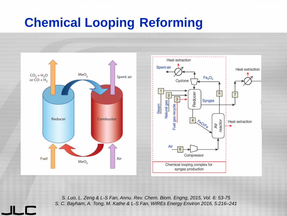
Chemical Looping Reforming
S. Luo, L. Zeng & L-S Fan, Annu. Rev. Chem. Biom. Engng, 2015, Vol. 6: 53-75
S. C. Bayham, A. Tong, M. Kathe & L-S Fan, WIREs Energy Environ 2016, 5:216–241

Chemical Looping Reforming
An alternative is to put a classical SMR reactor
inside the Chemical Looping Combustion loop
M. Ryden & A. Lyngfelt, International Journal of Hydrogen Energy 31 (2006) 1271 – 1283

Tri-reforming
C. Song, Am. Chem. Soc. Div. Fuel Chem. Prep. (2000), 45 (4), 772-776
Methane tri-reforming is a synergistic combination of the
three catalytic reforming processes

Tri-Reforming
Advantages
• Direct use of flue gases
• High methane conversion
• No CO2 separation
• Desired H2/CO
• Minimal coke formation
• Use of waste H2O/O2
• Simplified process
Disadvantages
• Requires oxy plant
• Novel process
• No commercial catalyst
• Requires high GHSV
• Heat & mass management
• Inert gas handling

Tri-reforming
Catalysts primarily Ni based with many
variations on promoters and supports
Ni/Ce-ZrO2 & Ni/ZrO2
Ni/MgO, Ni/MgO/CeZrO,
Ni/Al2O3
NiO-YSZ-CeO2
Ni/MgxTiyOz
Ni/SBA15
La-Ni/CeO2
Ni-CaO-ZrO2
Ni/β-SiC, Ni/CeO2
Ni/(CeO2,La2O3)/Al2O3
Rh-Ni/Ce-Al2O3
Ni/CeO2
Ce0.70La0.2Ni0.10O2-𝛿Ni-Mg/β-SiC
11%Ni@SiO2
Ni0Ce-Cr/Al2O3-ZrO2
Ni/MCM-41, Ni/SiC
M.H. Amin et al., APCChE 2015,. Melbourne (2015) 128-136


![Review Article Syngas Generation from Methane Using a ...fuels and chemicals [ ]. Conversion of methane to value-added products can be achieved in two ways, either via syn-gas (a mixture](https://static.fdocuments.net/doc/165x107/60c5acf47db970370d113ee4/review-article-syngas-generation-from-methane-using-a-fuels-and-chemicals-.jpg)