METER INSTALLATION SPECIFICATIONS HANDBOOK
29
METER INSTALLATION SPECIFICATIONS HANDBOOK
Transcript of METER INSTALLATION SPECIFICATIONS HANDBOOK
METER INSTALLATION
SPECIFICATIONS HANDBOOK

Rev. Date: 5/9/2016 S/standard/std/mtrhandbk
METER INSTALLATION SPECIFICATIONS HANDBOOK
This booklet is provided to assist customers, architects, engineers, contractors, developers, electricians and inspectors in planning and installing electric distribution and electric service.
It is not intended that any requirement be unduly restrictive or burdensome, but that these regulations and policies will serve to provide safety and expedite service connection by establishing uniform and equitable standards for electric service.
The standards herein are supplementary to and are not intended to conflict with any applicable City, County, or Community Ordinances, the National Electrical Safety Code, or the National Electrical Code.
Santee Cooper policy requirements for some clearances and standards exceed National Electrical Safety Code and National Electrical Code requirements.
No set rule or inspection will cover all conditions. Santee Cooper welcomes and encourages inquiries concerning unusual or special needs of our Customers and to provide clarification of our requirements and standards to serve you. Any and all exceptions to the specifications in this booklet must have prior Santee Cooper approval.

i
TABLE OF CONTENTS
SECTION 1 GENERAL INFORMATION 1
SECTION 2 ELECTRICAL SAFETY & CODE CLEARANCES 1
201 - Minimum Clearance from Overhead Lines 2 202 - Operating Equipment Near Energized Facilities 2 202.1 - Overhead 3 202.2 - Underground 3
SECTION 3 METERING 3
300 - Metering Installation and Ownership 3 301 - Meter Locations and Clearances 4 302 - Meter Sockets 5 302.1 - Maintenance and Repair of Meter Sockets 5 302.2 - Bonding Meter Sockets 5 302.3 - Meter Socket Wiring 6 303 - Current Transformer (CT) Metering 6 303.1 - CTs in Padmounted Transformers 6 303.2 - CT Cabinets 6 304 - Detached (Self-Supporting) Meter Mounting 6 305 - Moving or Removing Meters and Metering Equipment 7 306 - Pulse-Initiating Device Monitoring Electrical Demand 7 307 - Equipment Ahead (Source Side) of the Meter(s) 7 308 - Marking of Meter Sockets 7 309 - Load Splitting 7
SECTION 4 VOLTAGE STANDARDS AND SERVICE LIMITATIONS 7
401 - Overhead Service Area Secondary Voltage 8 402 - Underground Service Area Secondary Voltage 8 403 - Instantaneous Motor Demand (Voltage Flicker) 8 404 - Three Phase Motor-Protection Requirements 8 405 - Emergency Generators 8
SECTION 5 ELECTRIC SERVICE 8
SECTION 6 DISTRIBUTION SYSTEM DESIGN FOR LARGE TRACT/PROPERTY 9 DEVELOPMENT
SECTION 7 RIGHTS-OF-WAY, EASEMENTS & ACCESS 9
701 - General Restrictions of Easements/Rights-of-Way 9 702 - Aesthetics 10
ii
ii
SECTION 8 SYSTEM ALTERATION AND CONVERSION 10
800 - Alteration of Existing System 10 801 - Requirements for Work Performed on Time and Material Basis 10
SECTION 9 AREA LIGHTING 10
900 - Municipal, Roadway, Security and Decorative Lighting 10 DRAWING SHEETS
1 of 14 Typical Meter Socket Connections 11 2 of 14 600 Volt Service Drop Clearances For Buildings, Signs 12 And Other Installations (NESC Rule 234C3 and 235C1) 3 of 14 Clearances (NESC) From Conductors To Other Structures 13 4 of 14 Service Mast Installation 14 5 of 14 Meter Installation On Buildings With Sufficient Clearances 15 6 of 14 Overhead Installation For Mobile Homes Or Other Residences 16 7 of 14 Underground Installation For Mobile Homes Or Other Residences 17 8 of 14 Optional Underground Installation For Mobile Homes Or Other 18 Residences 9 of 14 Meter Installation On Buildings For Underground Service 19
10 of 14 Temporary Underground Service Installation 20 11 of 14 Temporary Overhead Service Installation 21 12 of 14 Underground Installation for 480V Service 22 13 of 14 Solar PV Installation 23 14 of 14 Padmount And URD Equipment Access Clearances 24 APPENDIX A (DEPARTMENT TELEPHONE NUMBERS) 25 May 2016
1
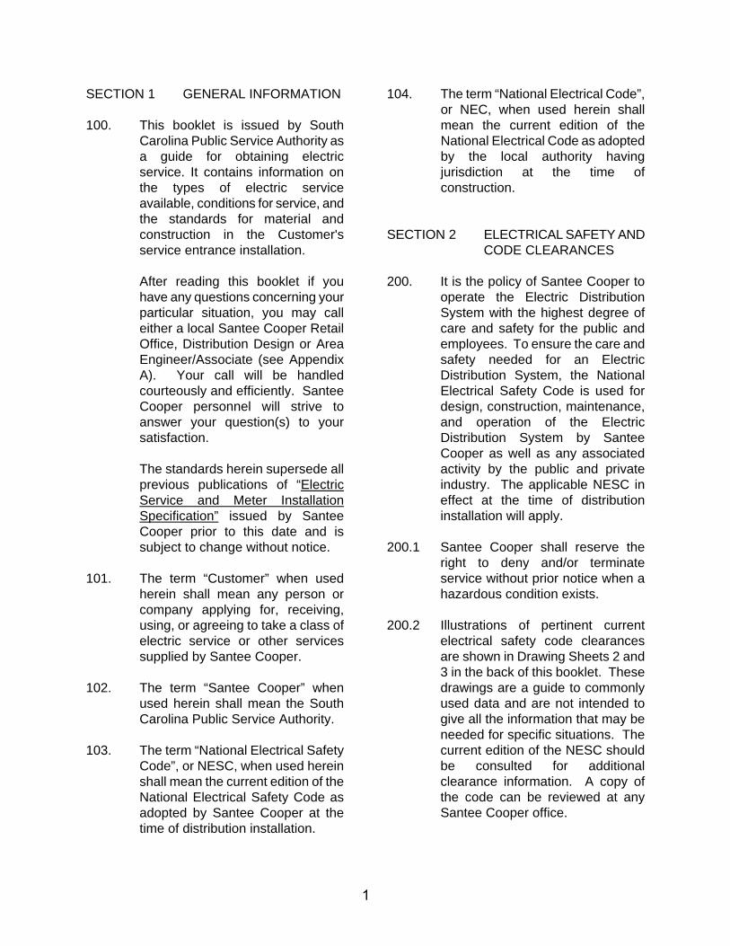
SECTION 1 GENERAL INFORMATION
100. This booklet is issued by South Carolina Public Service Authority as a guide for obtaining electric service. It contains information on the types of electric service available, conditions for service, and the standards for material and construction in the Customer's service entrance installation.
After reading this booklet if you have any questions concerning your particular situation, you may call either a local Santee Cooper Retail Office, Distribution Design or Area Engineer/Associate (see Appendix A). Your call will be handled courteously and efficiently. Santee Cooper personnel will strive to answer your question(s) to your satisfaction.
The standards herein supersede all previous publications of “Electric Service and Meter Installation Specification” issued by Santee Cooper prior to this date and is subject to change without notice.
101. The term “Customer” when used herein shall mean any person or company applying for, receiving, using, or agreeing to take a class of electric service or other services supplied by Santee Cooper.
102. The term “Santee Cooper” when used herein shall mean the South Carolina Public Service Authority.
103. The term “National Electrical Safety Code”, or NESC, when used herein shall mean the current edition of the National Electrical Safety Code as adopted by Santee Cooper at the time of distribution installation.
104. The term “National Electrical Code”, or NEC, when used herein shall mean the current edition of the National Electrical Code as adopted by the local authority having jurisdiction at the time of construction.
SECTION 2 ELECTRICAL SAFETY AND CODE CLEARANCES
200. It is the policy of Santee Cooper to operate the Electric Distribution System with the highest degree of care and safety for the public and employees. To ensure the care and safety needed for an Electric Distribution System, the National Electrical Safety Code is used for design, construction, maintenance, and operation of the Electric Distribution System by Santee Cooper as well as any associated activity by the public and private industry. The applicable NESC in effect at the time of distribution installation will apply.
200.1 Santee Cooper shall reserve the right to deny and/or terminate service without prior notice when a hazardous condition exists.
200.2 Illustrations of pertinent current electrical safety code clearances are shown in Drawing Sheets 2 and 3 in the back of this booklet. These drawings are a guide to commonly used data and are not intended to give all the information that may be needed for specific situations. The current edition of the NESC should be consulted for additional clearance information. A copy of the code can be reviewed at any Santee Cooper office.
2
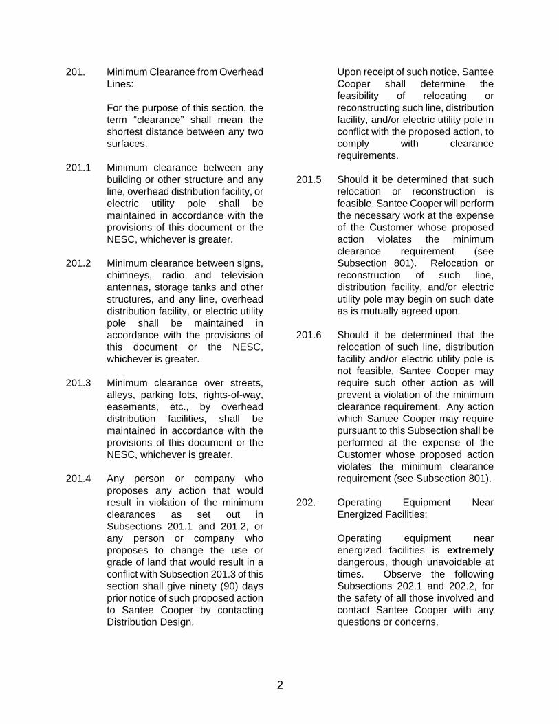
201. Minimum Clearance from Overhead Lines:
For the purpose of this section, the term “clearance” shall mean the shortest distance between any two surfaces.
201.1 Minimum clearance between any building or other structure and any line, overhead distribution facility, or electric utility pole shall be maintained in accordance with the provisions of this document or the NESC, whichever is greater.
201.2 Minimum clearance between signs, chimneys, radio and television antennas, storage tanks and other structures, and any line, overhead distribution facility, or electric utility pole shall be maintained in accordance with the provisions of this document or the NESC, whichever is greater.
201.3 Minimum clearance over streets, alleys, parking lots, rights-of-way, easements, etc., by overhead distribution facilities, shall be maintained in accordance with the provisions of this document or the NESC, whichever is greater.
201.4 Any person or company who proposes any action that would result in violation of the minimum clearances as set out in Subsections 201.1 and 201.2, or any person or company who proposes to change the use or grade of land that would result in a conflict with Subsection 201.3 of this section shall give ninety (90) days prior notice of such proposed action to Santee Cooper by contacting Distribution Design.
Upon receipt of such notice, Santee Cooper shall determine the feasibility of relocating or reconstructing such line, distribution facility, and/or electric utility pole in conflict with the proposed action, to comply with clearance requirements.
201.5 Should it be determined that such relocation or reconstruction is feasible, Santee Cooper will perform the necessary work at the expense of the Customer whose proposed action violates the minimum clearance requirement (see Subsection 801). Relocation or reconstruction of such line, distribution facility, and/or electric utility pole may begin on such date as is mutually agreed upon.
201.6 Should it be determined that the relocation of such line, distribution facility and/or electric utility pole is not feasible, Santee Cooper may require such other action as will prevent a violation of the minimum clearance requirement. Any action which Santee Cooper may require pursuant to this Subsection shall be performed at the expense of the Customer whose proposed action violates the minimum clearance requirement (see Subsection 801).
202. Operating Equipment Near Energized Facilities:
Operating equipment near energized facilities is extremely dangerous, though unavoidable at times. Observe the following Subsections 202.1 and 202.2, for the safety of all those involved and contact Santee Cooper with any questions or concerns.
3
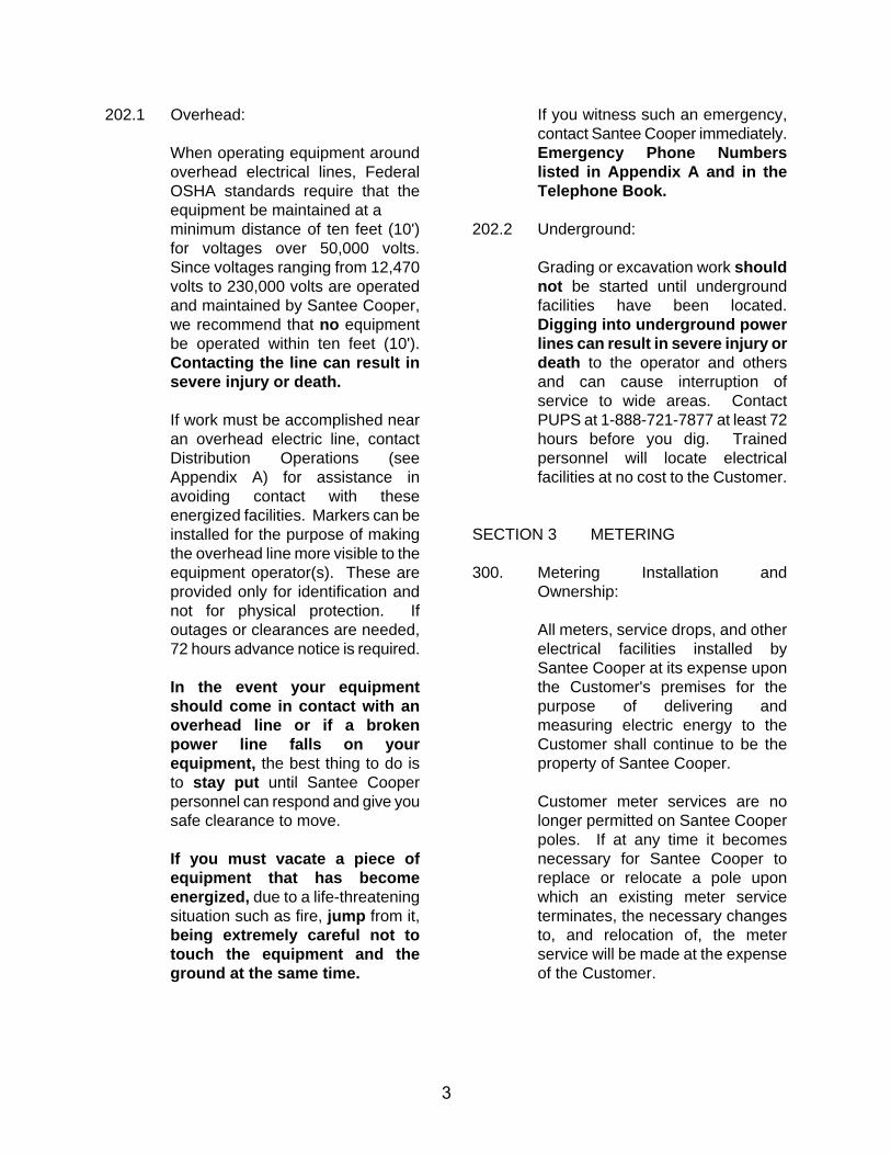
202.1 Overhead:
When operating equipment around overhead electrical lines, Federal OSHA standards require that the equipment be maintained at a minimum distance of ten feet (10') for voltages over 50,000 volts. Since voltages ranging from 12,470 volts to 230,000 volts are operated and maintained by Santee Cooper, we recommend that no equipment be operated within ten feet (10'). Contacting the line can result in severe injury or death.
If work must be accomplished near an overhead electric line, contact Distribution Operations (see Appendix A) for assistance in avoiding contact with these energized facilities. Markers can be installed for the purpose of making the overhead line more visible to the equipment operator(s). These are provided only for identification and not for physical protection. If outages or clearances are needed, 72 hours advance notice is required.
In the event your equipment should come in contact with an overhead line or if a broken power line falls on your equipment, the best thing to do is to stay put until Santee Cooper personnel can respond and give you safe clearance to move.
If you must vacate a piece of equipment that has become energized, due to a life-threatening situation such as fire, jump from it, being extremely careful not to touch the equipment and the ground at the same time.
If you witness such an emergency, contact Santee Cooper immediately. Emergency Phone Numbers listed in Appendix A and in the Telephone Book.
202.2 Underground:
Grading or excavation work should not be started until underground facilities have been located. Digging into underground power lines can result in severe injury or death to the operator and others and can cause interruption of service to wide areas. Contact PUPS at 1-888-721-7877 at least 72 hours before you dig. Trained personnel will locate electrical facilities at no cost to the Customer.
SECTION 3 METERING
300. Metering Installation and Ownership:
All meters, service drops, and other electrical facilities installed by Santee Cooper at its expense upon the Customer's premises for the purpose of delivering and measuring electric energy to the Customer shall continue to be the property of Santee Cooper.
Customer meter services are no longer permitted on Santee Cooper poles. If at any time it becomes necessary for Santee Cooper to replace or relocate a pole upon which an existing meter service terminates, the necessary changes to, and relocation of, the meter service will be made at the expense of the Customer.
4
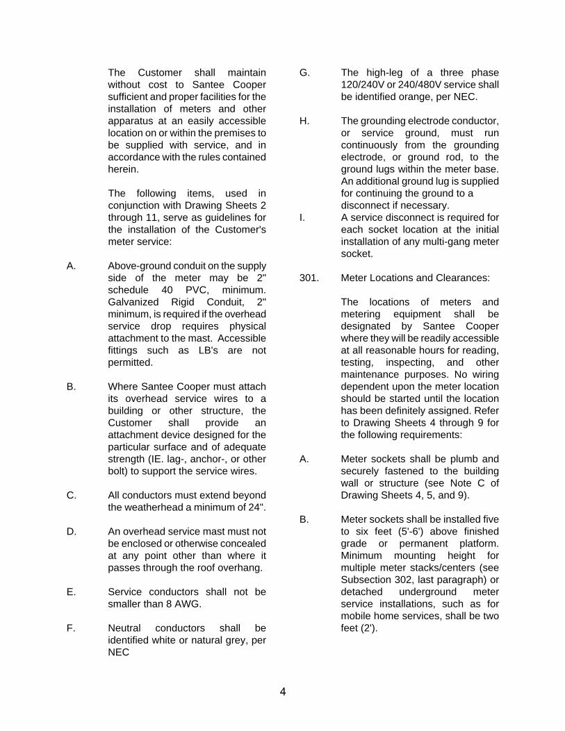
The Customer shall maintain without cost to Santee Cooper sufficient and proper facilities for the installation of meters and other apparatus at an easily accessible location on or within the premises to be supplied with service, and in accordance with the rules contained herein.
The following items, used in conjunction with Drawing Sheets 2 through 11, serve as guidelines for the installation of the Customer's meter service:
A. Above-ground conduit on the supply side of the meter may be 2" schedule 40 PVC, minimum. Galvanized Rigid Conduit, 2" minimum, is required if the overhead service drop requires physical attachment to the mast. Accessible fittings such as LB's are not permitted.
B. Where Santee Cooper must attach its overhead service wires to a building or other structure, the Customer shall provide an attachment device designed for the particular surface and of adequate strength (IE. lag-, anchor-, or other bolt) to support the service wires.
C. All conductors must extend beyond the weatherhead a minimum of 24".
D. An overhead service mast must not be enclosed or otherwise concealed at any point other than where it passes through the roof overhang.
E. Service conductors shall not be smaller than 8 AWG.
F. Neutral conductors shall be identified white or natural grey, per NEC
G. The high-leg of a three phase 120/240V or 240/480V service shall be identified orange, per NEC.
H. The grounding electrode conductor, or service ground, must run continuously from the grounding electrode, or ground rod, to the ground lugs within the meter base. An additional ground lug is supplied for continuing the ground to a disconnect if necessary.
I. A service disconnect is required for each socket location at the initial installation of any multi-gang meter socket.
301. Meter Locations and Clearances:
The locations of meters and metering equipment shall be designated by Santee Cooper where they will be readily accessible at all reasonable hours for reading, testing, inspecting, and other maintenance purposes. No wiring dependent upon the meter location should be started until the location has been definitely assigned. Refer to Drawing Sheets 4 through 9 for the following requirements:
A. Meter sockets shall be plumb and securely fastened to the building wall or structure (see Note C of Drawing Sheets 4, 5, and 9).
B. Meter sockets shall be installed five to six feet (5'-6') above finished grade or permanent platform. Minimum mounting height for multiple meter stacks/centers (see Subsection 302, last paragraph) or detached underground meter service installations, such as for mobile home services, shall be two feet (2').
5
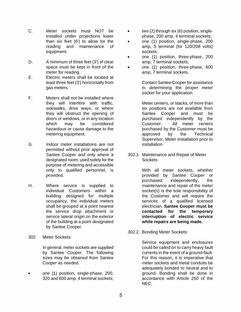
C. Meter sockets must NOT be installed under projections lower than six feet (6') to allow for the reading and maintenance of equipment.
D. A minimum of three feet (3') of clear space must be kept in front of the meter for reading.
E. Electric meters shall be located at least three feet (3') horizontally from gas meters.
F. Meters shall not be installed where they will interfere with traffic, sidewalks, drive ways, or where they will obstruct the opening of doors or windows, or in any location which may be considered hazardous or cause damage to the metering equipment.
G. Indoor meter installations are not permitted without prior approval of Santee Cooper and only where a designated room, used solely for the purpose of metering and accessible only to qualified personnel, is provided.
H. Where service is supplied to individual Customers within a building designed for multiple occupancy, the individual meters shall be grouped at a point nearest the service drop attachment or service lateral origin on the exterior of the building at a point designated by Santee Cooper.
302 Meter Sockets:
In general, meter sockets are supplied by Santee Cooper. The following sizes may be obtained from Santee Cooper as needed:
one (1) position, single-phase, 200,320 and 600 amp, 4 terminal sockets;
two (2) through six (6) position, single-phase, 200 amp, 4 terminal sockets;
one (1) position, single-phase, 200amp, 5 terminal (for 120/208 volts)sockets;
one (1) position, three-phase, 200amp, 7 terminal sockets;
one (1) position, three-phase, 600amp, 7 terminal sockets.
Contact Santee Cooper for assistance in determining the proper meter socket for your application.
Meter centers, or stacks, of more than six positions are not available from Santee Cooper and must be purchased independently by the Customer. All meter centers purchased by the Customer must be approved by the Technical Supervisor, Meter Installation prior to installation.
302.1. Maintenance and Repair of Meter Sockets:
With all meter sockets, whether provided by Santee Cooper or purchased independently, the maintenance and repair of the meter socket(s) is the sole responsibility of the Customer and will require the services of a qualified licensed electrician. Santee Cooper must be contacted for the temporary interruption of electric service while repairs are being made.
302.2. Bonding Meter Sockets:
Service equipment and enclosures could be called on to carry heavy fault currents in the event of a ground-fault. For this reason, it is imperative that meter sockets and metal conduits be adequately bonded to neutral and to ground. Bonding shall be done in accordance with Article 250 of the NEC.
6
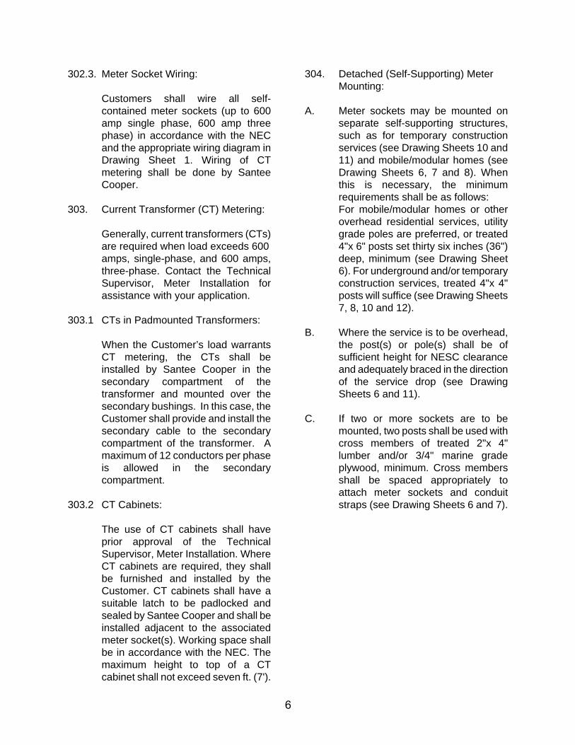
302.3. Meter Socket Wiring:
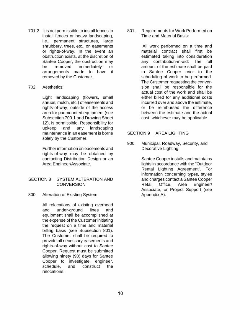
Customers shall wire all self-contained meter sockets (up to 600 amp single phase, 600 amp three phase) in accordance with the NEC and the appropriate wiring diagram in Drawing Sheet 1. Wiring of CT metering shall be done by Santee Cooper.
303. Current Transformer (CT) Metering:
Generally, current transformers (CTs) are required when load exceeds 600 amps, single-phase, and 600 amps, three-phase. Contact the Technical Supervisor, Meter Installation for assistance with your application.
303.1 CTs in Padmounted Transformers:
When the Customer’s load warrants CT metering, the CTs shall be installed by Santee Cooper in the secondary compartment of the transformer and mounted over the secondary bushings. In this case, the Customer shall provide and install the secondary cable to the secondary compartment of the transformer. A maximum of 12 conductors per phase is allowed in the secondary compartment.
303.2 CT Cabinets:
The use of CT cabinets shall have prior approval of the Technical Supervisor, Meter Installation. Where CT cabinets are required, they shall be furnished and installed by the Customer. CT cabinets shall have a suitable latch to be padlocked and sealed by Santee Cooper and shall be installed adjacent to the associated meter socket(s). Working space shall be in accordance with the NEC. The maximum height to top of a CT cabinet shall not exceed seven ft. (7').
304. Detached (Self-Supporting) Meter Mounting:
A. Meter sockets may be mounted on separate self-supporting structures, such as for temporary construction services (see Drawing Sheets 10 and 11) and mobile/modular homes (seeDrawing Sheets 6, 7 and 8). When this is necessary, the minimum requirements shall be as follows: For mobile/modular homes or other overhead residential services, utility grade poles are preferred, or treated 4"x 6" posts set thirty six inches (36") deep, minimum (see Drawing Sheet 6). For underground and/or temporary construction services, treated 4"x 4" posts will suffice (see Drawing Sheets 7, 8, 10 and 12).
B. Where the service is to be overhead, the post(s) or pole(s) shall be of sufficient height for NESC clearance and adequately braced in the direction of the service drop (see Drawing Sheets 6 and 11).
C. If two or more sockets are to be mounted, two posts shall be used with cross members of treated 2"x 4" lumber and/or 3/4" marine grade plywood, minimum. Cross members shall be spaced appropriately to attach meter sockets and conduit straps (see Drawing Sheets 6 and 7).
7
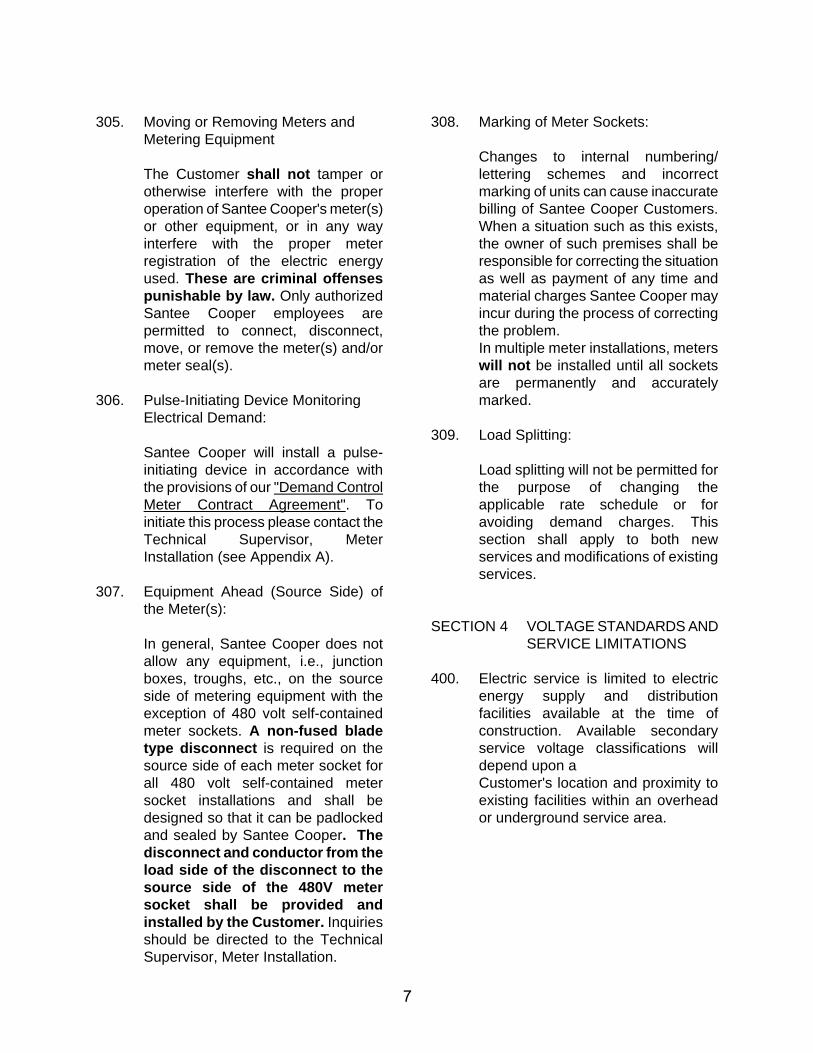
305. Moving or Removing Meters and Metering Equipment
The Customer shall not tamper or otherwise interfere with the proper operation of Santee Cooper's meter(s) or other equipment, or in any way interfere with the proper meter registration of the electric energy used. These are criminal offenses punishable by law. Only authorized Santee Cooper employees are permitted to connect, disconnect, move, or remove the meter(s) and/or meter seal(s).
306. Pulse-Initiating Device Monitoring Electrical Demand:
Santee Cooper will install a pulse-initiating device in accordance with the provisions of our "Demand Control Meter Contract Agreement". To initiate this process please contact the Technical Supervisor, Meter Installation (see Appendix A).
307. Equipment Ahead (Source Side) of the Meter(s):
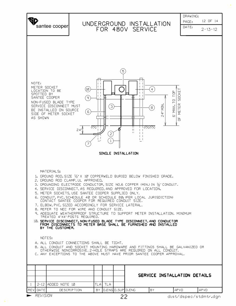
In general, Santee Cooper does not allow any equipment, i.e., junction boxes, troughs, etc., on the source side of metering equipment with the exception of 480 volt self-contained meter sockets. A non-fused blade type disconnect is required on the source side of each meter socket for all 480 volt self-contained meter socket installations and shall be designed so that it can be padlocked and sealed by Santee Cooper. The disconnect and conductor from the load side of the disconnect to the source side of the 480V meter socket shall be provided and installed by the Customer. Inquiries should be directed to the Technical Supervisor, Meter Installation.
308. Marking of Meter Sockets:
Changes to internal numbering/ lettering schemes and incorrect marking of units can cause inaccurate billing of Santee Cooper Customers. When a situation such as this exists, the owner of such premises shall be responsible for correcting the situation as well as payment of any time and material charges Santee Cooper may incur during the process of correcting the problem. In multiple meter installations, meters will not be installed until all sockets are permanently and accurately marked.
309. Load Splitting:
Load splitting will not be permitted for the purpose of changing the applicable rate schedule or for avoiding demand charges. This section shall apply to both new services and modifications of existing services.
SECTION 4 VOLTAGE STANDARDS AND SERVICE LIMITATIONS
400. Electric service is limited to electric energy supply and distribution facilities available at the time of construction. Available secondary service voltage classifications will depend upon a Customer's location and proximity to existing facilities within an overhead or underground service area.
8
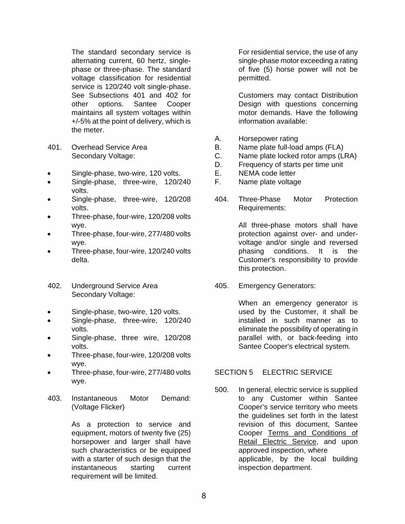
The standard secondary service is alternating current, 60 hertz, single-phase or three-phase. The standard voltage classification for residential service is 120/240 volt single-phase. See Subsections 401 and 402 for other options. Santee Cooper maintains all system voltages within +/-5% at the point of delivery, which is the meter.
401. Overhead Service Area Secondary Voltage:
Single-phase, two-wire, 120 volts. Single-phase, three-wire, 120/240
volts. Single-phase, three-wire, 120/208
volts. Three-phase, four-wire, 120/208 volts
wye. Three-phase, four-wire, 277/480 volts
wye. Three-phase, four-wire, 120/240 volts
delta.
402. Underground Service Area Secondary Voltage:
Single-phase, two-wire, 120 volts. Single-phase, three-wire, 120/240
volts. Single-phase, three wire, 120/208
volts. Three-phase, four-wire, 120/208 volts
wye. Three-phase, four-wire, 277/480 volts
wye.
403. Instantaneous Motor Demand: (Voltage Flicker)
As a protection to service and equipment, motors of twenty five (25) horsepower and larger shall have such characteristics or be equipped with a starter of such design that the instantaneous starting current requirement will be limited.
For residential service, the use of any single-phase motor exceeding a rating of five (5) horse power will not be permitted.
Customers may contact Distribution Design with questions concerning motor demands. Have the following information available:
A. Horsepower rating B. Name plate full-load amps (FLA) C. Name plate locked rotor amps (LRA) D. Frequency of starts per time unit E. NEMA code letter F. Name plate voltage
404. Three-Phase Motor Protection Requirements:
All three-phase motors shall have protection against over- and under-voltage and/or single and reversed phasing conditions. It is the Customer’s responsibility to provide this protection.
405. Emergency Generators:
When an emergency generator is used by the Customer, it shall be installed in such manner as to eliminate the possibility of operating in parallel with, or back-feeding into Santee Cooper's electrical system.
SECTION 5 ELECTRIC SERVICE
500. In general, electric service is supplied to any Customer within Santee Cooper’s service territory who meets the guidelines set forth in the latest revision of this document, Santee Cooper Terms and Conditions of Retail Electric Service, and upon approved inspection, where applicable, by the local building inspection department.
9
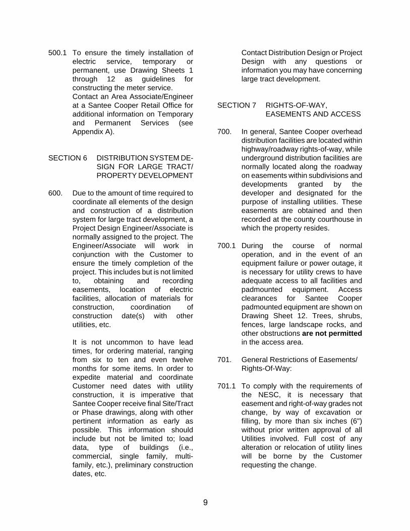
500.1 To ensure the timely installation of electric service, temporary or permanent, use Drawing Sheets 1 through 12 as guidelines for constructing the meter service. Contact an Area Associate/Engineer at a Santee Cooper Retail Office for additional information on Temporary and Permanent Services (see Appendix A).
SECTION 6 DISTRIBUTION SYSTEM DE-SIGN FOR LARGE TRACT/ PROPERTY DEVELOPMENT
600. Due to the amount of time required to coordinate all elements of the design and construction of a distribution system for large tract development, a Project Design Engineer/Associate is normally assigned to the project. The Engineer/Associate will work in conjunction with the Customer to ensure the timely completion of the project. This includes but is not limited to, obtaining and recording easements, location of electric facilities, allocation of materials for construction, coordination of construction date(s) with other utilities, etc.
It is not uncommon to have lead times, for ordering material, ranging from six to ten and even twelve months for some items. In order to expedite material and coordinate Customer need dates with utility construction, it is imperative that Santee Cooper receive final Site/Tract or Phase drawings, along with other pertinent information as early as possible. This information should include but not be limited to; load data, type of buildings (i.e., commercial, single family, multi-family, etc.), preliminary construction dates, etc.
Contact Distribution Design or Project Design with any questions or information you may have concerning large tract development.
SECTION 7 RIGHTS-OF-WAY, EASEMENTS AND ACCESS
700. In general, Santee Cooper overhead distribution facilities are located within highway/roadway rights-of-way, while underground distribution facilities are normally located along the roadway on easements within subdivisions and developments granted by the developer and designated for the purpose of installing utilities. These easements are obtained and then recorded at the county courthouse in which the property resides.
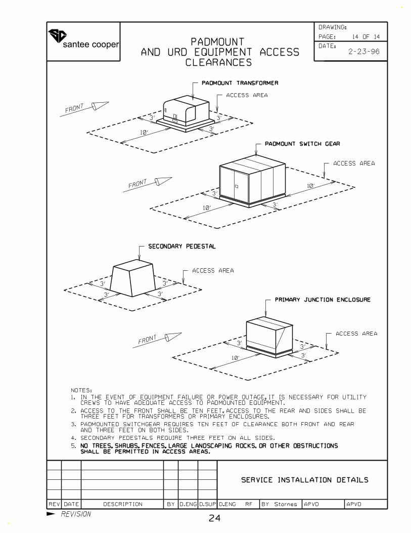
700.1 During the course of normal operation, and in the event of an equipment failure or power outage, it is necessary for utility crews to have adequate access to all facilities and padmounted equipment. Access clearances for Santee Cooper padmounted equipment are shown on Drawing Sheet 12. Trees, shrubs, fences, large landscape rocks, and other obstructions are not permitted in the access area.
701. General Restrictions of Easements/ Rights-Of-Way:
701.1 To comply with the requirements of the NESC, it is necessary that easement and right-of-way grades not change, by way of excavation or filling, by more than six inches (6") without prior written approval of all Utilities involved. Full cost of any alteration or relocation of utility lines will be borne by the Customer requesting the change.
10
701.2 It is not permissible to install fences to install fences or heavy landscaping, i.e., permanent structures, largeshrubbery, trees, etc., on easements or rights-of-way. In the event an obstruction exists, at the discretion of Santee Cooper, the obstruction may be removed immediately or arrangements made to have it removed by the Customer.
702. Aesthetics:
Light landscaping (flowers, small shrubs, mulch, etc.) of easements and rights-of-way, outside of the access area for padmounted equipment (see Subsection 700.1 and Drawing Sheet 12), is permissible. Responsibility for upkeep and any landscaping maintenance in an easement is borne solely by the Customer.
Further information on easements and rights-of-way may be obtained by contacting Distribution Design or an Area Engineer/Associate.
SECTION 8 SYSTEM ALTERATION AND CONVERSION
800. Alteration of Existing System:
All relocations of existing overhead and under-ground lines and equipment shall be accomplished at the expense of the Customer initiating the request on a time and material billing basis (see Subsection 801). The Customer shall be required to provide all necessary easements and rights-of-way without cost to Santee Cooper. Request must be submitted allowing ninety (90) days for Santee Cooper to investigate, engineer, schedule, and construct the relocations.
801. Requirements for Work Performed on Time and Material Basis:
All work performed on a time and material contract shall first be estimated taking into consideration any contribution-in-aid. The full amount of the estimate shall be paid to Santee Cooper prior to the scheduling of work to be performed. The Customer requesting the conver-sion shall be responsible for the actual cost of the work and shall be either billed for any additional costs incurred over and above the estimate, or be reimbursed the difference between the estimate and the actual cost, whichever may be applicable.
SECTION 9 AREA LIGHTING
900. Municipal, Roadway, Security, and Decorative Lighting:
Santee Cooper installs and maintains lights in accordance with the "Outdoor Rental Lighting Agreement". For information concerning types, styles and charges contact a Santee Cooper Retail Office, Area Engineer/ Associate, or Project Support (see Appendix A).
N
N
N
N
N N
N
1 2 3
N 1 2 3 1 2
N
N1 2
*
CAUTION:*
RF
SERVICE INSTALLATION DETAILS
Starnes
2 WIRE
SINGLE PHASE
4 WIRE
THREE PHASE
NETWORK
3 WIRE
METER SOCKET CONNECTIONS
TYPICAL
dist/dspec/stdmtr.dgn
3 WIRE (480V ONLY)
THREE PHASE
THE CENTER TERMINAL POSITION IN ALL OTHER ENCLOSURES, IE. SWITCHGEAR, MAIN PANELS, ETC.
THIS LEG IS REQUIRED BY THE NATIONAL ELECTRIC CODE TO BE IDENTIFIED ORANGE AND IN
2/97 REF REF1
11
2 9/02 REVISED 3-PH 480V TLA TLA JMP
1 OF 14
N
N
3 WIRE
SINGLE PHASE
FOR REFERENCE ONLY
INSTALLATION
DELTA
LEG ON
POWER
WITH LEVER BY-PASS
SINGLE PHASE 2 WIRE
TRAFFIC SIGNAL INSTALLATION
9-3-15
3 9/15 ADDED TRAFFIC SIGNAL TLA TLA
NEU. POSITION & CAUTION
DATE:
PAGE:
REV DATE DESCRIPTION BY D.SUPD.ENG D.ENG BY APVD APVD
DRAWING:
REVISION
santee cooper
3’
3’
ACCESSIBLE TO PEDESTRIANS
BALCONY OR DECK READILY
12" MIN.
SERVICE DROP
ELECTRIC
SERVICE DROP
COMMUNICATION
RF
SERVICE INSTALLATION DETAILS
OVER PORTION OF ROOF (OVERHANG)
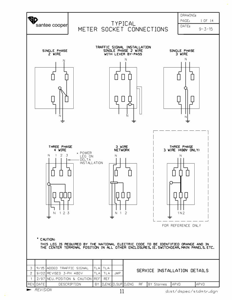
TO WINDOWS, DOORS, FIRE ESCAPES, ETC.
BETWEEN ELECTRIC POWER AND COMMUNICATION SERVICE DROPS
Starnes
dist/dspec/stdmtr.dgn
ETC.
FIRE ESCAPES,
WINDOWS, DOORS,
SIGNS AND OTHER INSTALLATIONS
CLEARANCES FOR BUILDINGS,
600 VOLT SERVICE DROP
(NESC RULE 234C3 AND 235C1)
12
10’
1 12/07 TLA TLA GAT
2 OF 14
APPLIES TO MULTIPLEX CABLE OR COVERED OPEN WIRE UP TO 300V.
FROM EDGE OF ROOF, AND WIRE CROSSES NOT MORE THAN 6’ OF ROOF.
18" - ROOF IS NOT READILY ACCESSIBLE, MAST NOT MORE THAN 4’
APPLIES TO MULTIPLEX CABLE OR COVERED OPEN WIRE UP TO 300V.
FROM EDGE OF ROOF, OR WIRE CROSSES ROOF MORE THAN 6’.
3’ - ROOF IS NOT READILY ACCESSIBLE, MAST IS MORE THAN 4’
ABOVE THE TOP LEVEL OF A WINDOW.
NOTE: DOES NOT APPLY TO MULTIPLEX CABLE
NESC RULE 234C3d2
NESC RULE 234C3d1
NESC TABLE 233-1
DIFFERENT POLES
MIN. 24" IF DROPS FROM
TABLE 235-540" MIN. NESC
2-2-12
4’
FOR MORE INFORMATION, SEE NESC RULE 234C3d
OR COVERED OPEN WIRE EXCEEDS 300V.
10’ - ROOF IS READILY ACCESSIBLE, MULTIPLEX CABLE EXCEEDS 750V,
2 2/12 EDIT CLEARANCES TLATLA TLA
EDIT CLEARANCES
FROM SAME POLE
MIN. 12" IF DROPS
NEC 800.44
DATE:
PAGE:
REV DATE DESCRIPTION BY D.SUPD.ENG D.ENG BY APVD APVD
DRAWING:
REVISION
santee cooper
V
H
V
V
VV
H
V
H
(IN FEET)
0-750 VOLTS
CABLE
MULTIPLEX
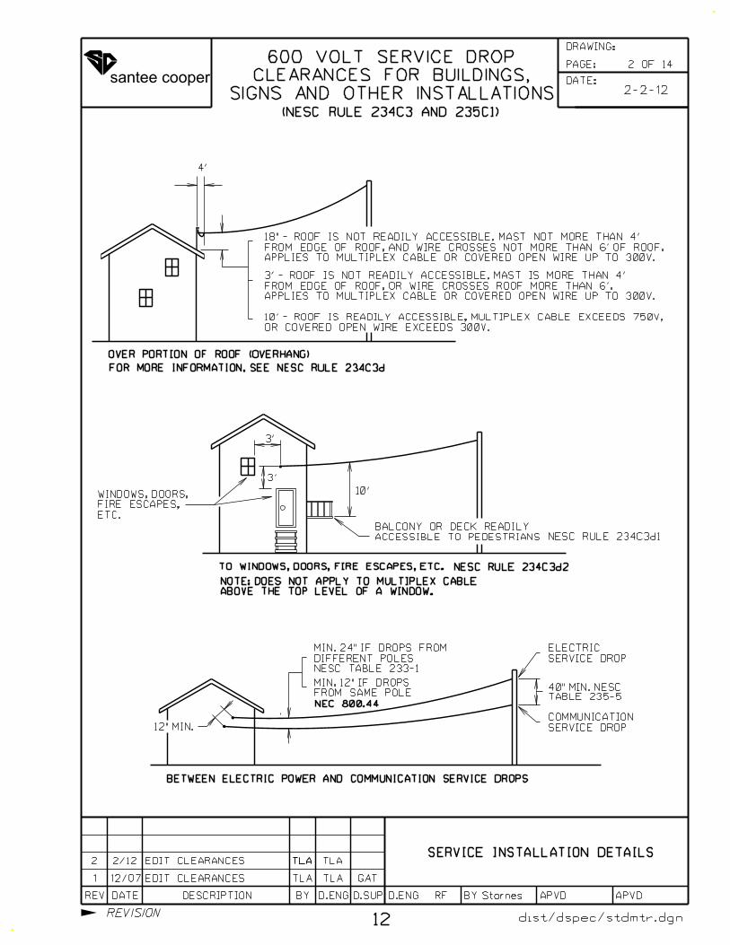
TRUCK TRAFFIC
OVER ROOFS ACCESSIBLE TO
H
H
H
V
VV
V
BUILDINGS
HORIZONTAL:H
V
5.0 5.5 7.5
(IN FEET)
0-750 VOLTS
CABLES
SECONDARY
OPEN WIRE
(1)
ACCESSIBLE TO PEDESTRIANS
BALCONIES AND AREAS READILY
TO WALLS, PROJECTIONS, WINDOWS,
(1)
ACCESSIBLE TO PEDESTRIANS
OVER ROOFS OR PROJECTIONS NOT READILY
(NO TRUCK OVER 8FT.)
TO VEHICLES UP TO 8FT. HEIGHT
HOT TUBS AND DECKS) AND ROOFS ACCESSIBLE
ACCESSABLE TO PEDESTRIANS (INCLUDING
OVER BALCONIES AND ROOFS READILY(2)
(3)
3.5 10.5 12.5
11.0 11.5 13.5
16.0 16.5 18.5
H
VERTICALV
3.5
3.5
5.5
6.0
7.5
8
SERVICE INSTALLATION DETAILS
RF Starnes
dist/dspec/stdmtr.dgn
H MINIMUM HORIZONTAL CLEARANCE=
V = MINIMUM VERTICAL CLEARANCE, MEASURED
EITHER DIAGONALLY OR VERTICALLY
VERTICAL:
HORIZONTAL
(IN FEET)
750V TO 22kV
NOTE: ALL VOLTAGES PHASE TO GROUND.
MOTEL
13
3 OF 14
2-13-12
NOT CLASSIFIED AS BUILDINGS OR BRIDGES,
ANTENNAS, TANKS AND OTHER INSTALLATIONS
SIGNS, CHIMNEYS. BILLBOARDS, RADIO AND TV
NOT READILY ACCESSIBLE TO PEDESTRIANS.
2-121 TLA TLAADDED TEXT TO SIGNS SECTION
OTHER STRUCTURES
CONDUCTORS TO
CLEARANCES (NESC) FROMDATE:
PAGE:
REV DATE DESCRIPTION BY D.SUPD.ENG D.ENG BY APVD APVD
DRAWING:
REVISION
santee cooper
RF
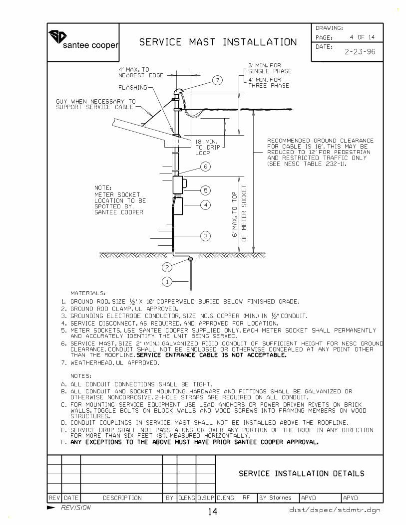
SERVICE MAST INSTALLATION2-23-96
NOTES:
ALL CONDUIT CONNECTIONS SHALL BE TIGHT.
OTHERWISE NONCORROSIVE. 2-HOLE STRAPS ARE REQUIRED ON ALL CONDUIT.
ALL CONDUIT AND SOCKET MOUNTING HARDWARE AND FITTINGS SHALL BE GALVANIZED OR
CONDUIT COUPLINGS IN SERVICE MAST SHALL NOT BE INSTALLED ABOVE THE ROOFLINE.
ANY EXCEPTIONS TO THE ABOVE MUST HAVE PRIOR SANTEE COOPER APPROVAL.
A.
B.
C.
D.
E.
F.
5
4
3
1
2
6
FLASHING
SUPPORT SERVICE CABLE
GUY WHEN NECESSARY TO
6’
MA
X.
TO
TO
P
OF
ME
TE
R
SO
CK
ET
LOOP
TO DRIP
18" MIN.
SINGLE PHASE
3’ MIN. FOR
THREE PHASE
4’ MIN. FOR
(SEE NESC TABLE 232-1).
AND RESTRICTED TRAFFIC ONLY
REDUCED TO 12’ FOR PEDESTRIAN
FOR CABLE IS 16’. THIS MAY BE
RECOMMENDED GROUND CLEARANCE
NOTE:
SANTEE COOPER
SPOTTED BY
LOCATION TO BE
METER SOCKET
SERVICE INSTALLATION DETAILS
Starnes
dist/dspec/stdmtr.dgn
STRUCTURES.
WALLS, TOGGLE BOLTS ON BLOCK WALLS AND WOOD SCREWS INTO FRAMING MEMBERS ON WOOD
FOR MOUNTING SERVICE EQUIPMENT USE LEAD ANCHORS OR POWER DRIVEN RIVETS ON BRICK
NEAREST EDGE
4’ MAX. TO
7
FOR MORE THAN SIX FEET (6’), MEASURED HORIZONTALLY.
SERVICE DROP SHALL NOT PASS ALONG OR OVER ANY PORTION OF THE ROOF IN ANY DIRECTION
GROUND ROD, SIZE �" X 10’ COPPERWELD BURIED BELOW FINISHED GRADE.
GROUNDING ELECTRODE CONDUCTOR, SIZE NO.6 COPPER (MIN.) IN �" CONDUIT.
SERVICE DISCONNECT, AS REQUIRED, AND APPROVED FOR LOCATION.
1.
2.
3.
4.
5.
6.
7.
MATERIALS:
GROUND ROD CLAMP, UL APPROVED.
AND ACCURATELY IDENTIFY THE UNIT BEING SERVED.
METER SOCKETS, USE SANTEE COOPER SUPPLIED ONLY. EACH METER SOCKET SHALL PERMANENTLY
SERVICE ENTRANCE CABLE IS NOT ACCEPTABLE.
WEATHERHEAD, UL APPROVED.
THAN THE ROOFLINE.
CLEARANCE. CONDUIT SHALL NOT BE ENCLOSED OR OTHERWISE CONCEALED AT ANY POINT OTHER
SERVICE MAST, SIZE 2" (MIN.) GALVANIZED RIGID CONDUIT OF SUFFICIENT HEIGHT FOR NESC GROUND
14
4 OF 14
DATE:
PAGE:
REV DATE DESCRIPTION BY D.SUPD.ENG D.ENG BY APVD APVD
DRAWING:
REVISION
santee cooper
GROUND ROD, SIZE �" X 10’ COPPERWELD BURIED BELOW FINISHED GRADE.
GROUNDING ELECTRODE CONDUCTOR, SIZE NO.6 COPPER (MIN.) IN �" CONDUIT.
SERVICE DISCONNECT, AS REQUIRED, AND APPROVED FOR LOCATION.
1.
2.
3.
4.
5.
6.
7.
MATERIALS:
NOTES:
ALL CONDUIT CONNECTIONS SHALL BE TIGHT.
OTHERWISE NONCORROSIVE. 2-HOLE STRAPS ARE REQUIRED ON ALL CONDUIT.
ALL CONDUIT AND SOCKET MOUNTING HARDWARE AND FITTINGS SHALL BE GALVANIZED OR
ANY EXCEPTIONS TO THE ABOVE MUST HAVE PRIOR SANTEE COOPER APPROVAL.
A.
B.
C.
D.
5
4
3
1
2
6
6’
MA
X.
TO
TO
P
OF
ME
TE
R
SO
CK
ET
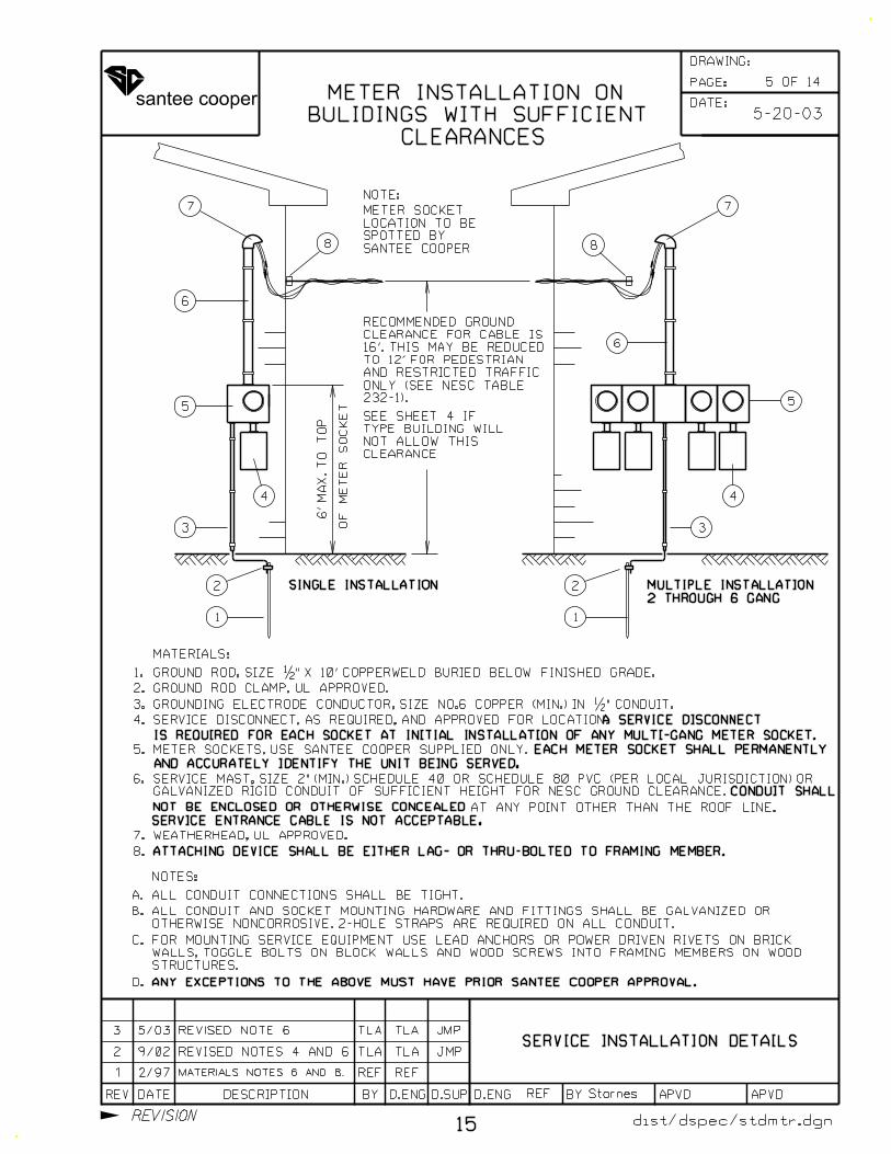
GROUND ROD CLAMP, UL APPROVED.
SERVICE INSTALLATION DETAILS
7 7
Starnes
232-1).
ONLY (SEE NESC TABLE
AND RESTRICTED TRAFFIC
TO 12’ FOR PEDESTRIAN
16’. THIS MAY BE REDUCED
CLEARANCE FOR CABLE IS
RECOMMENDED GROUND
NOTE:
SANTEE COOPER
SPOTTED BY
LOCATION TO BE
METER SOCKET
2
1
3
5
4
6
SINGLE INSTALLATION
CLEARANCE
NOT ALLOW THIS
TYPE BUILDING WILL
SEE SHEET 4 IF
CLEARANCES
BULIDINGS WITH SUFFICIENT
METER INSTALLATION ON
dist/dspec/stdmtr.dgn
STRUCTURES.
WALLS, TOGGLE BOLTS ON BLOCK WALLS AND WOOD SCREWS INTO FRAMING MEMBERS ON WOOD
FOR MOUNTING SERVICE EQUIPMENT USE LEAD ANCHORS OR POWER DRIVEN RIVETS ON BRICK
2 THROUGH 6 GANG
MULTIPLE INSTALLATION
SERVICE ENTRANCE CABLE IS NOT ACCEPTABLE.
WEATHERHEAD, UL APPROVED.
8 8
8.
1 2/97 REF REF
REF
ATTACHING DEVICE SHALL BE EITHER LAG- OR THRU-BOLTED TO FRAMING MEMBER.
MATERIALS NOTES 6 AND 8.
A SERVICE DISCONNECT
IS REQUIRED FOR EACH SOCKET AT INITIAL INSTALLATION OF ANY MULTI-GANG METER SOCKET.
METER SOCKETS, USE SANTEE COOPER SUPPLIED ONLY. EACH METER SOCKET SHALL PERMANENTLY
AND ACCURATELY IDENTIFY THE UNIT BEING SERVED.
5-20-03
REVISED NOTES 4 AND 62 9/02 TLA TLA JMP
15
GALVANIZED RIGID CONDUIT OF SUFFICIENT HEIGHT FOR NESC GROUND CLEARANCE.
SERVICE MAST, SIZE 2" (MIN.) SCHEDULE 40 OR SCHEDULE 80 PVC (PER LOCAL JURISDICTION) OR
CONDUIT SHALL
NOT BE ENCLOSED OR OTHERWISE CONCEALED AT ANY POINT OTHER THAN THE ROOF LINE.
3 REVISED NOTE 6 TLA TLA JMP5/03
5 OF 14
DATE:
PAGE:
REV DATE DESCRIPTION BY D.SUPD.ENG D.ENG BY APVD APVD
DRAWING:
REVISION
santee cooper
SERVICE INSTALLATION DETAILS
OTHERWISE NONCORROSIVE. 2-HOLE STRAPS ARE REQUIRED ON ALL CONDUIT.
ALL CONDUIT AND SOCKET MOUNTING HARDWARE AND FITTINGS SHALL BE GALVANIZED OR
5
4
3
1
2
6
6’
MA
X.
TO
TO
P
OF
ME
TE
R
SO
CK
ET
7
NOTE:
SANTEE COOPER
SPOTTED BY
LOCATION TO BE
METER SOCKET
2
1
8
5
4
SINGLE INSTALLATION
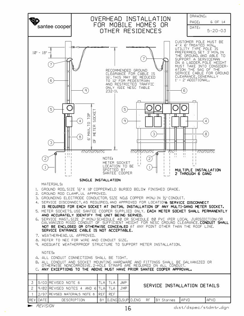
10" - 18"
1’ - 2’ ADDITIONAL.
CLEARANCE, GENERALLY
SERVICE CABLE FOR GROUND
ATION THE SAG OF THE
MUST TAKE INTO CONSIDER-
ON A LADDER. POLE HEIGHT
SUPPORT A SERVICEMAN
THE GROUND, AND ABLE TO
PREFERRED, SET 3’ MIN. IN
UTILITY TYPE POLE IS
4" X 6" TREATED MIN.,
CUSTOMER POLE MUST BE
83
9
RF Starnes
dist/dspec/stdmtr.dgn
7
232-1).
ONLY (SEE NESC TABLE
AND RESTRICTED TRAFFIC
TO 12’ FOR PEDESTRIAN
16’. THIS MAY BE REDUCED
CLEARANCE FOR CABLE IS
RECOMMENDED GROUND
6
2 THROUGH 6 GANG
MULTIPLE INSTALLATION
9
OTHER RESIDENCES
FOR MOBILE HOMES OR
OVERHEAD INSTALLATION
1 2/97 REVISED MATERIALS NOTE 6 REF REF
5-20-03
2 9/02 TLA TLA JMP
16
GALVANIZED RIGID CONDUIT OF SUFFICIENT HEIGHT FOR NESC GROUND CLEARANCE.
SERVICE MAST, SIZE 2" (MIN.) SCHEDULE 40 OR SCHEDULE 80 PVC (PER LOCAL JURISDICTION) OR
REVISED NOTES 4 AND 6
3 REVISED NOTE 6 TLA TLA JMP5/03
NOTES:
ALL CONDUIT CONNECTIONS SHALL BE TIGHT.
ANY EXCEPTIONS TO THE ABOVE MUST HAVE PRIOR SANTEE COOPER APPROVAL.
A.
B.
C.
REFER TO NEC FOR WIRE AND CONDUIT SIZE.8.
ADEQUATE WEATHERPROOF STRUCTURE TO SUPPORT METER INSTALLATION.9.
GROUND ROD, SIZE �" X 10’ COPPERWELD BURIED BELOW FINISHED GRADE.
GROUNDING ELECTRODE CONDUCTOR, SIZE NO.6 COPPER (MIN.) IN �" CONDUIT.
SERVICE DISCONNECT, AS REQUIRED, AND APPROVED FOR LOCATION.
1.
2.
3.
4.
5.
6.
7.
MATERIALS:
GROUND ROD CLAMP, UL APPROVED.
WEATHERHEAD, UL APPROVED.
SERVICE ENTRANCE CABLE IS NOT ACCEPTABLE.
A SERVICE DISCONNECT
IS REQUIRED FOR EACH SOCKET AT INITIAL INSTALLATION OF ANY MULTI-GANG METER SOCKET.
METER SOCKETS, USE SANTEE COOPER SUPPLIED ONLY. EACH METER SOCKET SHALL PERMANENTLY
AND ACCURATELY IDENTIFY THE UNIT BEING SERVED.
CONDUIT SHALL
NOT BE ENCLOSED OR OTHERWISE CONCEALED AT ANY POINT OTHER THAN THE ROOF LINE.
6 OF 14
DATE:
PAGE:
REV DATE DESCRIPTION BY D.SUPD.ENG D.ENG BY APVD APVD
DRAWING:
REVISION
santee cooper
SERVICE INSTALLATION DETAILSSERVICE INSTALLATION DETAILS
6.
7.
NOTES:
ALL CONDUIT CONNECTIONS SHALL BE TIGHT.
OTHERWISE NONCORROSIVE. 2-HOLE STRAPS ARE REQUIRED ON ALL CONDUIT.
ALL CONDUIT AND SOCKET MOUNTING HARDWARE AND FITTINGS SHALL BE GALVANIZED OR
ANY EXCEPTIONS TO THE ABOVE MUST HAVE PRIOR SANTEE COOPER APPROVAL.
A.
B.
C.
6’
MA
X.
TO
TO
P
OF
ME
TE
R
SO
CK
ET
2
1
8
5
4
SINGLE INSTALLATION
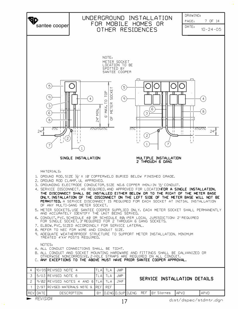
REFER TO NEC FOR WIRE AND CONDUIT SIZE.8.
9.
9
24"
2
1
4
8
6
7
5
9
3
3
7
6
24"
MIN.
SANTEE COOPER
SPOTTED BY
LOCATION TO BE
METER SOCKET
NOTE:
Starnes
dist/dspec/stdmtr.dgn
24"
2 THROUGH 6 GANG
MULTIPLE INSTALLATION
GROUND ROD, SIZE �" X 10’ COPPERWELD BURIED BELOW FINISHED GRADE.
GROUNDING ELECTRODE CONDUCTOR, SIZE NO.6 COPPER (MIN.) IN �" CONDUIT.
1.
2.
3.
4.
5.
MATERIALS:
GROUND ROD CLAMP, UL APPROVED.
ELBOW, PVC, SIZED ACCORDINGLY FOR SERVICE LATERAL.
OTHER RESIDENCES
FOR MOBILE HOMES OR
UNDERGROUND INSTALLATION
1 2/97 REVISED MATERIALS NOTE 9. REF REF
REF
TREATED 4"X4" POSTS REQUIRED.
ADEQUATE WEATHERPROOF STRUCTURE TO SUPPORT METER INSTALLATION. MINIMUM
2 9/02 TLA TLA JMP
17
3 5/03 REVISED NOTE 6 TLA TLA JMP
REVISED NOTES 4 AND 6
FOR SINGLE SOCKET, 3" REQUIRED FOR 2 THROUGH 6 GANG SOCKETS.
CONDUIT, PVC, SCHEDULE 40 OR SCHEDULE 80; (PER LOCAL JURISDICTION) 2" REQUIRED
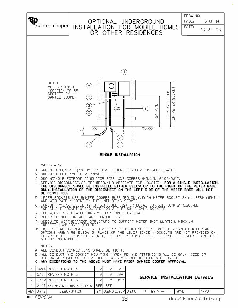
SERVICE DISCONNECT, AS REQUIRED, AND APPROVED FOR LOCATION.FOR A SINGLE INSTALLATION,
AND ACCURATELY IDENTIFY THE UNIT BEING SERVED.
METER SOCKETS, USE SANTEE COOPER SUPPLIED ONLY. EACH METER SOCKET SHALL PERMANENTLY
10-24-05
4 10/05 TLA TLA JMPREVISED NOTE 4
7 OF 14
PERMITTED.
ONLY. INSTALLATION OF THE DISCONNECT ON THE LEFT SIDE OF THE METER BASE WILL NOT BE
THE DISCONNECT SHALL BE INSTALLED EITHER BELOW OR TO THE RIGHT OF THE METER BASE
A SERVICE DISCONNECT IS REQUIRED FOR EACH SOCKET AT INITIAL INSTALLATION
OF ANY MULTI-GANG METER SOCKET.
DATE:
PAGE:
REV DATE DESCRIPTION BY D.SUPD.ENG D.ENG BY APVD APVD
DRAWING:
REVISION
santee cooper
SERVICE INSTALLATION DETAILS
Starnes
SERVICE INSTALLATION DETAILSSERVICE INSTALLATION DETAILS
6.
7.
NOTES:
ALL CONDUIT CONNECTIONS SHALL BE TIGHT.
ANY EXCEPTIONS TO THE ABOVE MUST HAVE PRIOR SANTEE COOPER APPROVAL.
A.
B.
C.
6’
MA
X.
TO
TO
P
OF
ME
TE
R
SO
CK
ET
SINGLE INSTALLATION
REFER TO NEC FOR WIRE AND CONDUIT SIZE.8.
9.
24"
3
6
7
5
9
4
10.
10
2
1
SANTEE COOPER
SPOTTED BY
LOCATION TO BE
METER SOCKET
NOTE:
8
dist/dspec/stdmtr.dgn
24"
MIN.
GROUND ROD, SIZE �" X 10’ COPPERWELD BURIED BELOW FINISHED GRADE.
GROUNDING ELECTRODE CONDUCTOR, SIZE NO.6 COPPER (MIN.) IN �" CONDUIT.
SERVICE DISCONNECT, AS REQUIRED, AND APPROVED FOR LOCATION.
1.
2.
3.
4.
5.
MATERIALS:
GROUND ROD CLAMP, UL APPROVED.
ELBOW, PVC, SIZED ACCORDINGLY FOR SERVICE LATERAL.
1 2/97 REVISED MATERIALS NOTE 9. REF REF
REF
2 9/02 TLA TLA JMP
18
3 5/03
REVISED NOTE 6
REVISED NOTE 6 TLA TLA JMP
FOR A SINGLE INSTALLATION,
10-24-05
4 10/05 TLA TLA JMPREVISED NOTE 4
8 OF 14
OTHERWISE NONCORROSIVE. 2-HOLE STRAPS ARE REQUIRED ON ALL CONDUIT.
ALL CONDUIT AND SOCKET MOUNTING HARDWARE AND FITTINGS SHALL BE GALVANIZED OR
A COUPLING NIPPLE.
THIS SIDE OF THE METER SOCKET, THE CUSTOMER MAY ELECT TO DRILL THE SOCKET AND USE
OPTIONS ARE; A 90° ELBOW IN PLACE OF THE LB, OR, SINCE KNOCKOUTS ARE NOT PROVIDED ON
LB, SIZED ACCORDINGLY, TO ALLOW FOR SIDE-MOUNTING OF SERVICE DISCONNECT. ACCEPTABLE
AND ACCURATELY IDENTIFY THE UNIT BEING SERVED.
METER SOCKETS, USE SANTEE COOPER SUPPLIED ONLY. EACH METER SOCKET SHALL PERMANENTLY
TREATED 4"X4" POSTS REQUIRED.
ADEQUATE WEATHERPROOF STRUCTURE TO SUPPORT METER INSTALLATION. MINIMUM
FOR SINGLE SOCKET, 3" REQUIRED FOR 2 THROUGH 6 GANG SOCKETS.
CONDUIT, PVC, SCHEDULE 40 OR SCHEDULE 80; (PER LOCAL JURISDICTION) 2" REQUIRED
BE PERMITTED.
ONLY. INSTALLATION OF THE DISCONNECT ON THE LEFT SIDE OF THE METER BASE WILL NOT
THE DISCONNECT SHALL BE INSTALLED EITHER BELOW OR TO THE RIGHT OF THE METER BASE
OR OTHER RESIDENCES
INSTALLATION FOR MOBILE HOMES
OPTIONAL UNDERGROUNDDATE:
PAGE:
REV DATE DESCRIPTION BY D.SUPD.ENG D.ENG BY APVD APVD
DRAWING:
REVISION
santee cooper
RF
SERVICE INSTALLATION DETAILS
StarnesRF
NOTES:
ALL CONDUIT CONNECTIONS SHALL BE TIGHT.
OTHERWISE NONCORROSIVE. 2-HOLE STRAPS ARE REQUIRED ON ALL CONDUIT.
ALL CONDUIT AND SOCKET MOUNTING HARDWARE AND FITTINGS SHALL BE GALVANIZED OR
ANY EXCEPTIONS TO THE ABOVE MUST HAVE PRIOR SANTEE COOPER APPROVAL.
A.
B.
C.
D.
SERVICE INSTALLATION DETAILS
2
1
3
5
4
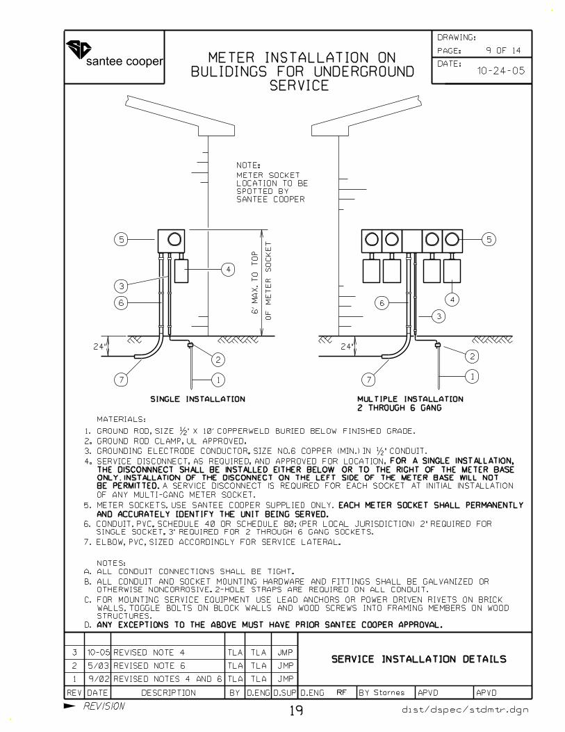
SERVICE
BULIDINGS FOR UNDERGROUND
METER INSTALLATION ON
6’
MA
X.
TO
TO
P
OF
ME
TE
R
SO
CK
ET
SINGLE INSTALLATION
24"
2
1
4
6
7
5
3
NOTE:
24"
7
6
dist/dspec/stdmtr.dgn
STRUCTURES.
WALLS, TOGGLE BOLTS ON BLOCK WALLS AND WOOD SCREWS INTO FRAMING MEMBERS ON WOOD
FOR MOUNTING SERVICE EQUIPMENT USE LEAD ANCHORS OR POWER DRIVEN RIVETS ON BRICK
6.
7.
GROUND ROD, SIZE �" X 10’ COPPERWELD BURIED BELOW FINISHED GRADE.
GROUNDING ELECTRODE CONDUCTOR, SIZE NO.6 COPPER (MIN.) IN �" CONDUIT.
SERVICE DISCONNECT, AS REQUIRED, AND APPROVED FOR LOCATION.
1.
2.
3.
4.
5.
MATERIALS:
GROUND ROD CLAMP, UL APPROVED.
ELBOW, PVC, SIZED ACCORDINGLY FOR SERVICE LATERAL.
METER SOCKETS, USE SANTEE COOPER SUPPLIED ONLY. EACH METER SOCKET SHALL PERMANENTLY
AND ACCURATELY IDENTIFY THE UNIT BEING SERVED.
1 9/02 TLA TLA JMP
19
REVISED NOTES 4 AND 6
2 5/03 REVISED NOTE 6 TLA TLA JMP
FOR A SINGLE INSTALLATION,
10-24-05
3 10-05 TLA TLA JMPREVISED NOTE 4
9 OF 14
2 THROUGH 6 GANG
MULTIPLE INSTALLATION
SANTEE COOPER
SPOTTED BY
LOCATION TO BE
METER SOCKET
BE PERMITTED.
ONLY. INSTALLATION OF THE DISCONNECT ON THE LEFT SIDE OF THE METER BASE WILL NOT
THE DISCONNNECT SHALL BE INSTALLED EITHER BELOW OR TO THE RIGHT OF THE METER BASE
OF ANY MULTI-GANG METER SOCKET.
A SERVICE DISCONNECT IS REQUIRED FOR EACH SOCKET AT INITIAL INSTALLATION
SINGLE SOCKET, 3" REQUIRED FOR 2 THROUGH 6 GANG SOCKETS.
CONDUIT, PVC, SCHEDULE 40 OR SCHEDULE 80; (PER LOCAL JURISDICTION) 2" REQUIRED FOR
DATE:
PAGE:
REV DATE DESCRIPTION BY D.SUPD.ENG D.ENG BY APVD APVD
DRAWING:
REVISION
santee cooper
RF StarnesRFRF
4.
5.
6.
7.
NOTES:
ALL CONDUIT CONNECTIONS SHALL BE TIGHT.
ANY EXCEPTIONS TO THE ABOVE MUST HAVE PRIOR SANTEE COOPER APPROVAL.
A.
B.
C.
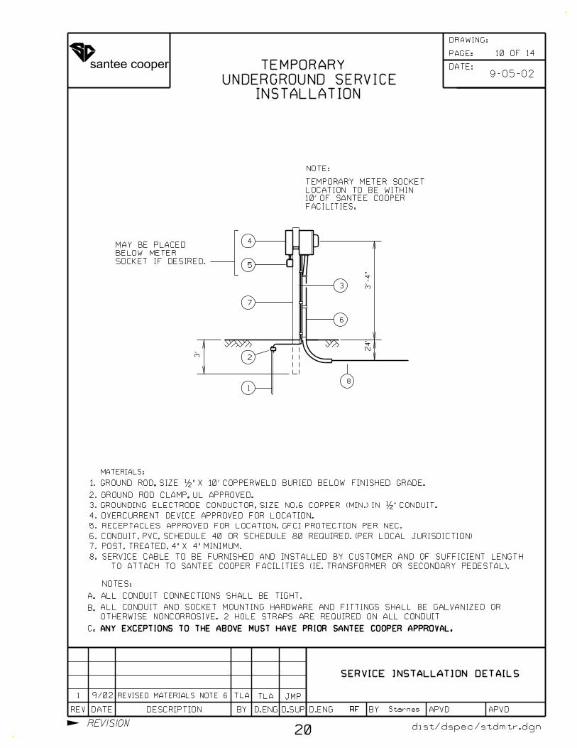
OVERCURRENT DEVICE APPROVED FOR LOCATION.
RECEPTACLES APPROVED FOR LOCATION. GFCI PROTECTION PER NEC.
8.
TO ATTACH TO SANTEE COOPER FACILITIES (IE. TRANSFORMER OR SECONDARY PEDESTAL).
SERVICE CABLE TO BE FURNISHED AND INSTALLED BY CUSTOMER AND OF SUFFICIENT LENGTH
2
1
3
4
8
7
5
6
SOCKET IF DESIRED.
BELOW METER
MAY BE PLACED
3’-
4"
24"
3’
FACILITIES.
10’ OF SANTEE COOPER
LOCATION TO BE WITHIN
TEMPORARY METER SOCKET
GROUND ROD, SIZE �" X 10’ COPPERWELD BURIED BELOW FINISHED GRADE.
GROUNDING ELECTRODE CONDUCTOR, SIZE NO.6 COPPER (MIN.) IN �" CONDUIT.
1.
2.
3.
MATERIALS:
GROUND ROD CLAMP, UL APPROVED.
POST, TREATED, 4" X 4" MINIMUM.
1 REVISED MATERIALS NOTE 6
INSTALLATION
UNDERGROUND SERVICE
TEMPORARY
OTHERWISE NONCORROSIVE. 2 HOLE STRAPS ARE REQUIRED ON ALL CONDUIT
ALL CONDUIT AND SOCKET MOUNTING HARDWARE AND FITTINGS SHALL BE GALVANIZED OR
CONDUIT, PVC, SCHEDULE 40 OR SCHEDULE 80 REQUIRED. (PER LOCAL JURISDICTION)
20
TLA TLA JMP9/02
SERVICE INSTALLATION DETAILS
NOTE:
9-05-02
dist/dspec/stdmtr.dgn
10 OF 14
DATE:
PAGE:
REV DATE DESCRIPTION BY D.SUPD.ENG D.ENG BY APVD APVD
DRAWING:
REVISION
santee cooper
SERVICE INSTALLATION DETAILS
Starnes
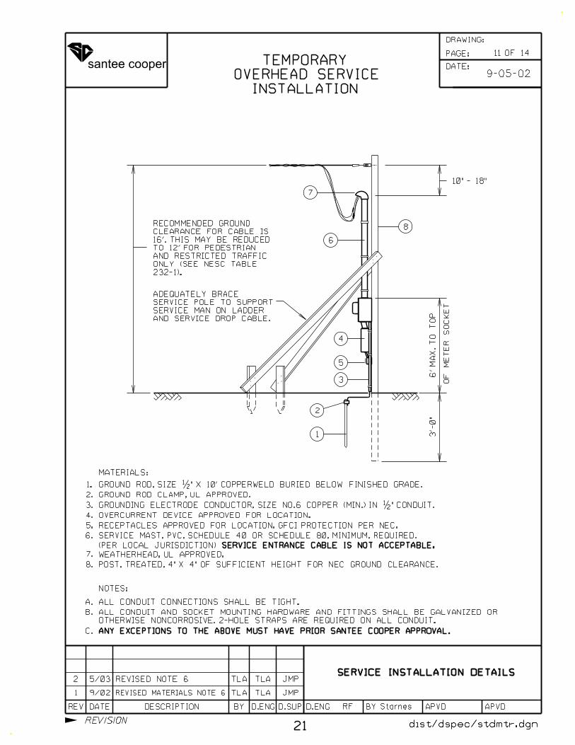
232-1).
ONLY (SEE NESC TABLE
AND RESTRICTED TRAFFIC
TO 12’ FOR PEDESTRIAN
16’. THIS MAY BE REDUCED
CLEARANCE FOR CABLE IS
RECOMMENDED GROUND
7
dist/dspec/stdmtr.dgndist/dspec/stdmtr.dgn
4.
5.
6.
7.
NOTES:
ALL CONDUIT CONNECTIONS SHALL BE TIGHT.
OTHERWISE NONCORROSIVE. 2-HOLE STRAPS ARE REQUIRED ON ALL CONDUIT.
ALL CONDUIT AND SOCKET MOUNTING HARDWARE AND FITTINGS SHALL BE GALVANIZED OR
ANY EXCEPTIONS TO THE ABOVE MUST HAVE PRIOR SANTEE COOPER APPROVAL.
A.
B.
C.
OVERCURRENT DEVICE APPROVED FOR LOCATION.
RECEPTACLES APPROVED FOR LOCATION. GFCI PROTECTION PER NEC.
8.
2
1
3
4
5
INSTALLATION
OVERHEAD SERVICE
TEMPORARY
3’-
0"
6’
MA
X.
TO
TO
P
OF
ME
TE
R
SO
CK
ET
10" - 18"
8
6
AND SERVICE DROP CABLE.
SERVICE MAN ON LADDER
SERVICE POLE TO SUPPORT
ADEQUATELY BRACE
GROUND ROD, SIZE �" X 10’ COPPERWELD BURIED BELOW FINISHED GRADE.
GROUNDING ELECTRODE CONDUCTOR, SIZE NO.6 COPPER (MIN.) IN �" CONDUIT.
1.
2.
3.
MATERIALS:
GROUND ROD CLAMP, UL APPROVED.
SERVICE ENTRANCE CABLE IS NOT ACCEPTABLE.
WEATHERHEAD, UL APPROVED.
POST, TREATED, 4" X 4" OF SUFFICIENT HEIGHT FOR NEC GROUND CLEARANCE.
9-05-02
RF
1 9/02 TLA TLA JMP
21
REVISED MATERIALS NOTE 6
REVISED NOTE 62 5/03 TLA TLA JMP
(PER LOCAL JURISDICTION)
SERVICE MAST, PVC, SCHEDULE 40 OR SCHEDULE 80, MINIMUM, REQUIRED.
SERVICE INSTALLATION DETAILS
11 OF 14
DATE:
PAGE:
REV DATE DESCRIPTION BY D.SUPD.ENG D.ENG BY APVD APVD
DRAWING:
REVISION
santee cooper
SERVICE INSTALLATION DETAILSSERVICE INSTALLATION DETAILSSERVICE INSTALLATION DETAILS
6.
7.
NOTES:
ALL CONDUIT CONNECTIONS SHALL BE TIGHT.
OTHERWISE NONCORROSIVE. 2-HOLE STRAPS ARE REQUIRED ON ALL CONDUIT.
ALL CONDUIT AND SOCKET MOUNTING HARDWARE AND FITTINGS SHALL BE GALVANIZED OR
A.
B.
C.
6’
MA
X.
TO
TO
P
OF
ME
TE
R
SO
CK
ET
SINGLE INSTALLATION
REFER TO NEC FOR WIRE AND CONDUIT SIZE.8.
9.
24"
3
6
7
9
2
1
SANTEE COOPER
SPOTTED BY
LOCATION TO BE
METER SOCKET
NOTE:
8
dist/dspec/stdmtr.dgn
24"
MIN.
GROUND ROD, SIZE �" X 10’ COPPERWELD BURIED BELOW FINISHED GRADE.
GROUNDING ELECTRODE CONDUCTOR, SIZE NO.6 COPPER (MIN.) IN �" CONDUIT.
1.
2.
3.
4.
5.
MATERIALS:
GROUND ROD CLAMP, UL APPROVED.
ELBOW, PVC, SIZED ACCORDINGLY FOR SERVICE LATERAL.
TREATED 4"X4" POSTS REQUIRED.
ADEQUATE WEATHERPROOF STRUCTURE TO SUPPORT METER INSTALLATION. MINIMUM
5
4
FOR 480V SERVICE
UNDERGROUND INSTALLATION
CONTACT SANTEE COOPER FOR REQUIRED CONDUIT SIZE.
CONDUIT, PVC, SCHEDULE 40 OR SCHEDULE 80; (PER LOCAL JURISDICTION)
SERVICE DISCONNECT, AS REQUIRED, AND APPROVED FOR LOCATION.
10
10.
12 OF 14
22
METER SOCKETS, USE SANTEE COOPER SUPPLIED ONLY.
2-121 TLA TLAADDED NOTE 10
AS SHOWN
SIDE OF METER SOCKET
BE INSTALLED ON SOURCE
SERVICE DISCONNECT MUST
NON-FUSED BLADE TYPE
ANY EXCEPTIONS TO THE ABOVE MUST HAVE PRIOR SANTEE COOPER APPROVAL.
BY THE CUSTOMER.
FROM DISCONNECTS TO METER BASE SHALL BE FURNISHED AND INSTALLED
SERVICE DISCONNECT, NON-FUSED BLADE TYPE DISCONNECT, AND CONDUCTOR
2-13-12DATE:
PAGE:
REV DATE DESCRIPTION BY D.SUPD.ENG D.ENG BY APVD APVD
DRAWING:
REVISION
santee cooper
SERVICE INSTALLATION DETAILS
dist/dspec/stdmtr.dgn
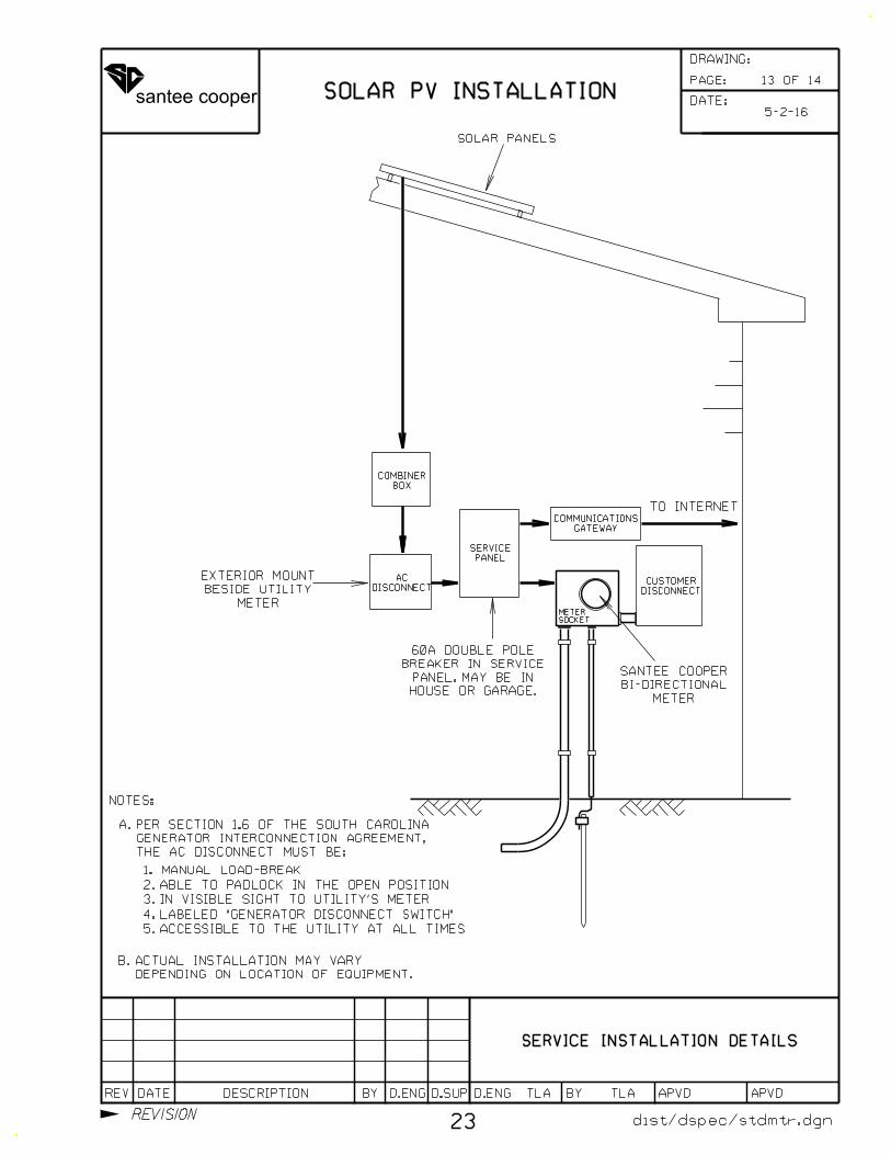
TO INTERNET
SOLAR PANELS
METER
BESIDE UTILITY
EXTERIOR MOUNT
NOTES:
BOX
COMBINER
DISCONNECT
AC
PANEL
SERVICE
GATEWAY
COMMUNICATIONS
DISCONNECT
CUSTOMER
HOUSE OR GARAGE.
PANEL. MAY BE IN
BREAKER IN SERVICE
60A DOUBLE POLE
SOLAR PV INSTALLATION13 OF 14
5-2-16
TLA TLA
SOCKET
METER
METER
BI-DIRECTIONAL
SANTEE COOPER
2. ABLE TO PADLOCK IN THE OPEN POSITION
4. LABELED "GENERATOR DISCONNECT SWITCH"
1. MANUAL LOAD-BREAK
5. ACCESSIBLE TO THE UTILITY AT ALL TIMES
3. IN VISIBLE SIGHT TO UTILITY’S METER
THE AC DISCONNECT MUST BE:
GENERATOR INTERCONNECTION AGREEMENT,
A. PER SECTION 1.6 OF THE SOUTH CAROLINA
DEPENDING ON LOCATION OF EQUIPMENT.
B. ACTUAL INSTALLATION MAY VARY
23
DATE:
PAGE:
REV DATE DESCRIPTION BY D.SUPD.ENG D.ENG BY APVD APVD
DRAWING:
REVISION
santee cooper
RF Starnes
SERVICE INSTALLATION DETAILS
2-23-96
CLEARANCES
AND URD EQUIPMENT ACCESS
PADMOUNT
3’
3’3’
PADMOUNT TRANSFORMER
3’
3’
3’
3’3’
3’
SECONDARY PEDESTAL
3’3’
3’
PRIMARY JUNCTION ENCLOSURE
NOTES:
ACCESS AREA
FRONT
PADMOUNT SWITCH GEAR
ACCESS AREA
FRONT
ACCESS AREA
FRONTACCESS AREA
1.
CREWS TO HAVE ADEQUATE ACCESS TO PADMOUNTED EQUIPMENT.
IN THE EVENT OF EQUIPMENT FAILURE OR POWER OUTAGE, IT IS NECESSARY FOR UTILITY
2.
THREE FEET FOR TRANSFORMERS OR PRIMARY ENCLOSURES.
ACCESS TO THE FRONT SHALL BE TEN FEET. ACCESS TO THE REAR AND SIDES SHALL BE
3.
AND THREE FEET ON BOTH SIDES.
PADMOUNTED SWITCHGEAR REQUIRES TEN FEET OF CLEARANCE BOTH FRONT AND REAR
4. SECONDARY PEDESTALS REQUIRE THREE FEET ON ALL SIDES.
5.
SHALL BE PERMITTED IN ACCESS AREAS.
NO TREES, SHRUBS, FENCES, LARGE LANDSCAPING ROCKS, OR OTHER OBSTRUCTIONS
10’
10’
10’
10’
14 OF 14
24
DATE:
PAGE:
REV DATE DESCRIPTION BY D.SUPD.ENG D.ENG BY APVD APVD
DRAWING:
REVISION
santee cooper
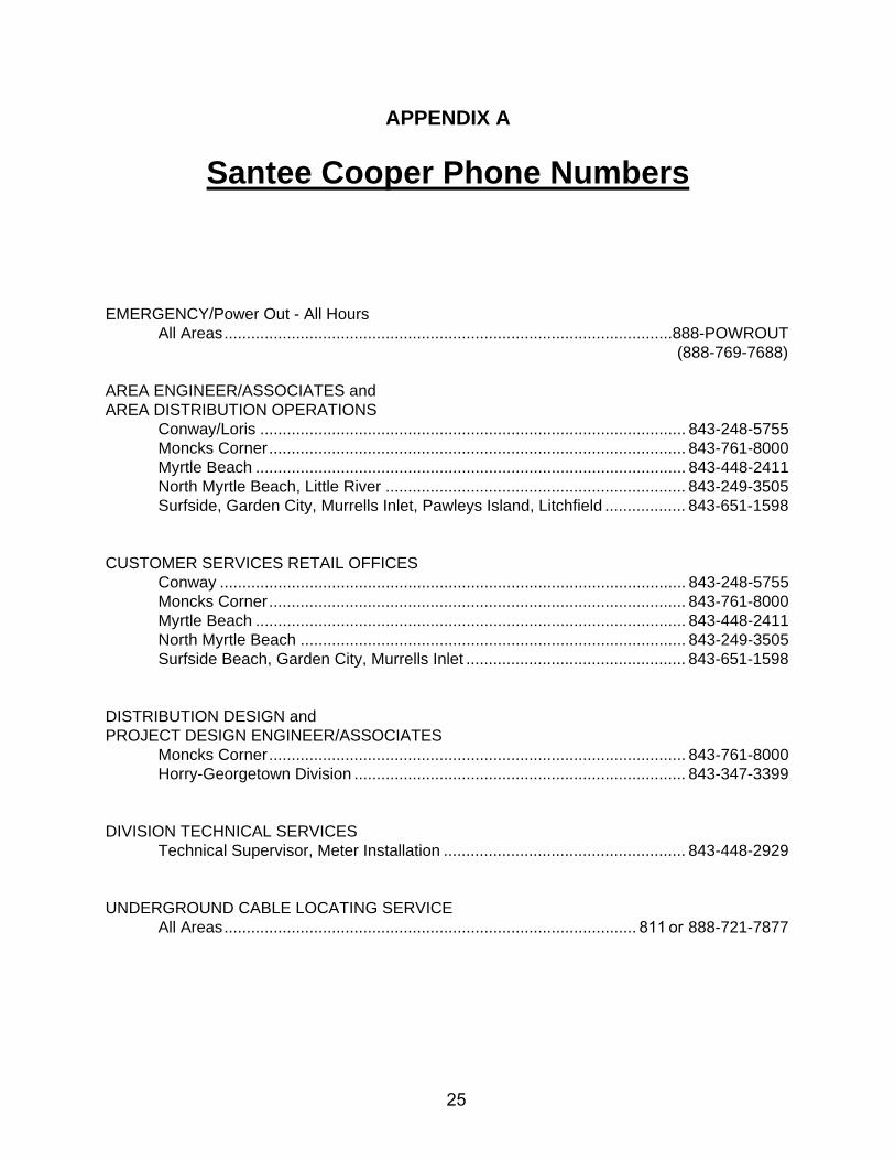
APPENDIX A
Santee Cooper Phone Numbers
EMERGENCY/Power Out - All Hours All Areas .................................................................................................... 888-POWROUT
(888-769-7688)
AREA ENGINEER/ASSOCIATES and AREA DISTRIBUTION OPERATIONS
Conway/Loris ............................................................................................... 843-248-5755 Moncks Corner ............................................................................................. 843-761-8000 Myrtle Beach ................................................................................................ 843-448-2411 North Myrtle Beach, Little River ................................................................... 843-249-3505 Surfside, Garden City, Murrells Inlet, Pawleys Island, Litchfield .................. 843-651-1598
CUSTOMER SERVICES RETAIL OFFICES Conway ........................................................................................................ 843-248-5755 Moncks Corner ............................................................................................. 843-761-8000 Myrtle Beach ................................................................................................ 843-448-2411 North Myrtle Beach ...................................................................................... 843-249-3505 Surfside Beach, Garden City, Murrells Inlet ................................................. 843-651-1598
DISTRIBUTION DESIGN and PROJECT DESIGN ENGINEER/ASSOCIATES
Moncks Corner ............................................................................................. 843-761-8000 Horry-Georgetown Division .......................................................................... 843-347-3399
DIVISION TECHNICAL SERVICES Technical Supervisor, Meter Installation ...................................................... 843-448-2929
UNDERGROUND CABLE LOCATING SERVICE All Areas ............................................................................................ 811 or 888-721-7877
25