
Metamodelisation to support Test and Evolution
83
HAL Id: tel-01352817 https://hal.inria.fr/tel-01352817 Submitted on 18 Aug 2016 HAL is a multi-disciplinary open access archive for the deposit and dissemination of sci- entific research documents, whether they are pub- lished or not. The documents may come from teaching and research institutions in France or abroad, or from public or private research centers. L’archive ouverte pluridisciplinaire HAL, est destinée au dépôt et à la diffusion de documents scientifiques de niveau recherche, publiés ou non, émanant des établissements d’enseignement et de recherche français ou étrangers, des laboratoires publics ou privés. Metamodelisation to support Test and Evolution Anne Etien To cite this version: Anne Etien. Metamodelisation to support Test and Evolution. Langage de programmation [cs.PL]. Université de Lille, 2016. tel-01352817
Transcript of Metamodelisation to support Test and Evolution

HAL Id: tel-01352817https://hal.inria.fr/tel-01352817
Submitted on 18 Aug 2016
HAL is a multi-disciplinary open accessarchive for the deposit and dissemination of sci-entific research documents, whether they are pub-lished or not. The documents may come fromteaching and research institutions in France orabroad, or from public or private research centers.
L’archive ouverte pluridisciplinaire HAL, estdestinée au dépôt et à la diffusion de documentsscientifiques de niveau recherche, publiés ou non,émanant des établissements d’enseignement et derecherche français ou étrangers, des laboratoirespublics ou privés.
Metamodelisation to support Test and EvolutionAnne Etien
To cite this version:Anne Etien. Metamodelisation to support Test and Evolution. Langage de programmation [cs.PL].Université de Lille, 2016. �tel-01352817�

Universite Lille 1, Sciences et Technologies
Specialite Informatique Ecole doctorale Science Pour l’Ingenieur (Lille)
Metamodelisation to supportTest and Evolution
Habilitation a Diriger les Recherches
Universite Lille 1, Sciences et Technologies
(specialite informatique)
presentee et soutenue publiquement le 28 juin 2016
par
Anne Etien
Composition du jury
President : Mme Laurence Duchien
Rapporteurs : M. Serge Demeyer,Mme Marianne Huchard,M. Jurgen Vinju
Examinateur : M. Xavier Blanc
Garant : M. Stephane Ducasse
Centre de Recherche en Informatique Signal et Automatique de Lille — UMR CNRS 9189INRIA Lille - Nord Europe
Numero d’ordre: XXXXX


Contents
1 Introduction 1
1.1 Goal of this Document . . . . . . . . . . . . . . . . . . . . . . . 1
1.2 Software Maintenance, Testing and Evolution . . . . . . . . . . . 2
1.3 Models Everywhere . . . . . . . . . . . . . . . . . . . . . . . . . 4
1.4 Content of this Document . . . . . . . . . . . . . . . . . . . . . . 4
2 Designing Model Transformation Chains 7
2.1 Problems . . . . . . . . . . . . . . . . . . . . . . . . . . . . . . 7
2.2 Previous State of the Art . . . . . . . . . . . . . . . . . . . . . . 8
2.3 Contributions . . . . . . . . . . . . . . . . . . . . . . . . . . . . 11
2.3.1 Localised Transformations . . . . . . . . . . . . . . . . . 11
2.3.2 Composition of Localised Transformations . . . . . . . . 13
2.3.3 Building Model Transformation Chains . . . . . . . . . . 15
2.3.4 Localised Transformations Characteristics . . . . . . . . . 16
2.4 Perspectives . . . . . . . . . . . . . . . . . . . . . . . . . . . . . 17
3 Software Architecture Modifications 19
3.1 Problems . . . . . . . . . . . . . . . . . . . . . . . . . . . . . . 19
3.2 Previous State of the Art . . . . . . . . . . . . . . . . . . . . . . 20
3.3 Contributions . . . . . . . . . . . . . . . . . . . . . . . . . . . . 22
3.3.1 Architectural Modifications and Constraint Validations . . 22
3.3.2 Transformation Pattern Definition . . . . . . . . . . . . . 23
3.3.3 Relevance of Transformation Patterns . . . . . . . . . . . 26
3.3.4 Automating Transformation Pattern Application . . . . . 28
3.4 Perspectives . . . . . . . . . . . . . . . . . . . . . . . . . . . . . 29
4 Testing Supported by Metamodelling 33
4.1 Problems . . . . . . . . . . . . . . . . . . . . . . . . . . . . . . 33
4.2 Previous State of the Art . . . . . . . . . . . . . . . . . . . . . . 34
4.3 Contributions . . . . . . . . . . . . . . . . . . . . . . . . . . . . 36
i

ii CONTENTS
4.3.1 Trace Mechanism . . . . . . . . . . . . . . . . . . . . . . 36
4.3.2 Error localisation . . . . . . . . . . . . . . . . . . . . . . 38
4.3.3 Mutation Analysis and Model Transformations . . . . . . 39
4.3.4 Test Set Selection after a Change in the Program . . . . . 42
4.4 Perspectives . . . . . . . . . . . . . . . . . . . . . . . . . . . . . 48
5 Co-evolution Supported by Metamodels 51
5.1 Problems . . . . . . . . . . . . . . . . . . . . . . . . . . . . . . 51
5.2 Previous State of the Art . . . . . . . . . . . . . . . . . . . . . . 52
5.3 Contributions . . . . . . . . . . . . . . . . . . . . . . . . . . . . 55
5.3.1 Transformation-Metamodel Co-evolution . . . . . . . . . 55
5.3.2 Database and Program Co-Evolution. . . . . . . . . . . . 57
5.4 Perspectives . . . . . . . . . . . . . . . . . . . . . . . . . . . . . 61
6 Conclusion and Perspectives 63
6.1 Main Results . . . . . . . . . . . . . . . . . . . . . . . . . . . . 63
6.2 Perspectives . . . . . . . . . . . . . . . . . . . . . . . . . . . . . 65

CHAPTER 1
Introduction
During ten years, I have been working on two different domains Model DrivenEngineering and Software Maintenance but with a single target: Designing systemsof good quality, easily maintainable. The reasoning was also the same: I proposedsolutions based on metamodels or models to provide genericity and independencefrom the programming languages of the results. The considered systems are eitherchains of model transformations (i.e. not the program generated from models butthe, model based, compiler itself) or traditional programs. Quality can be ensuredand measured from different ways. In this document, I only focus on tests.
1.1 Goal of this Document
In this document of Habilitation to Supervise Research, I aimed at illustrating threecomplementary qualities that I consider necessary to supervise research:
• ability to supervise novice or young researchers. Our mission as supervisoris to teach novice and young researchers to search without mandatorily ob-taining results, to search again and find relevant results and to present them. Ihad the opportunity to supervise 4 PhD students (including one who alreadydefended) and 4 master students. I also accompanied in their research, onepost doc and one ATER.
• ability to collaborate. In my opinion, research is synonym of exchange. Ex-change between people from different horizons with different backgroundsand ways of thinking. Collaborations can be either academic, between re-searchers, or industrial to answer real problems. I worked in close collab-oration with French or international researchers. Moreover, since I had theopportunity to do my own research, I have been trying to answer concreteand real issues. Some were initiated by companies, others were transferredto the industry.
• ability to have a vision. Research in a domain does not stop with the defenseof a PhD student, or the end of a project. On the contrary, it is mostly theoccasion to raise new issues. Having a vision, is also having the ability todecompose long term research topics into short or mid term issues.
1

2 CHAPTER 1. INTRODUCTION
All the results presented in this document were reached in collaboration witheither a novice researcher that I supervised or a colleague. Details of the presentedresults can be found in articles published in international journals, conferences andworkshops.
1.2 Software Maintenance, Testing and Evolution
This document presents my work of these ten last years. My career follows a “tra-ditional" path. After a PhD at the University Paris 1 on information systems, Icame to Lille in 2006 for a postdoctoral stay to work on model transformations inthe Dart team common to Inria and Lifl Lab (now CRIStAL). After one year, I wasenrolled as associate professor teaching at Polytech Lille and doing my researchin the Dart team. Its core business was real-time embedded systems dealing withmassively parallel data. The embedded systems were generated from models usingmodel transformation chains. My research concerned the chains. In 2011, the Inriateam stopped. A new one was created without any reference to models. My workhad no place in this new organisation. After trying during one year to work alone ormove to somewhere else, I finally decided to join the RMod team common to Inriaand Lifl lab. The goal of RMoD is to support remodularisation and developmentof modular object-oriented applications. This objective is tackled from two com-plementary perspectives: reengineering and constructs for dynamic programminglanguages. I have been working on the reengineering part where we propose newanalyses to understand and restructure existing large applications based on abstractrepresentations.
Looking back to these years, two topics are constantly studied: testing andevolution. The analysed systems are different, model transformation chains or tra-ditional programs but the main objective remains the same: ease maintenance. Itcan be noticed that this thematic was already strongly present in my PhD disserta-tion. Moreover, the used means i.e., modelling and metamodelling also federatesmy research.
Before briefly presenting the topics tackled in this document, I explain why Iam studying software maintenance.
Why Software Maintenance? Several studies showed that activities after deliv-ery are pre-dominant in software engineering and correspond to 90% of the totalcost of a typical software [Pigoski 1997, Seacord 2003]. These activities corre-spond to software maintenance that is the modification of a software product afterdelivery to correct faults, to improve performance or other attributes [ISO 2006].Past studies (reported in [Pigoski 1997]) showed that, contrary to common belief,corrective maintenance (i.e. diagnosing and fixing errors) represents only a smallpart of all maintenance (21%). Most software maintenance (50%) is done to add

1.2. SOFTWARE MAINTENANCE, TESTING AND EVOLUTION 3
new features (perfective maintenance). The modification of the system to copewith changes in the software environment (adaptive maintenance) corresponds to25%. The system is modified to increase its maintainability or reliability (4%) toprevent problems in the future (preventive maintenance).
Moreover, Lehman’s first law of software evolution (law of Continuing Change,[Lehman 1980]) specifies that “a program that is used undergoes continual changeor becomes progressively less useful." A corollary to this law is that software main-tenance is a sign of success: considering the costs associated to software mainte-nance, it is performed only for software systems which utility is perceived as morevaluable than this cost. This is a conclusion that goes against the usual perceptionof the activity, but maintenance actually means that a system is useful and that itsusers see a value in its continuing operation.
Anticipation and Architecture Modifications. Object, aspect and model par-adigms were introduced to enhance reusability, modularity and ease successiveevolutions the software systems meet. Even if these paradigms were introducedfor these purposes, for each software system, maintenance must be anticipatedfrom the design phase [Budgen 2003]. However, everything cannot be anticipatedand anyway, according to Lehman’s second law (law of Increasing Complexity,[Lehman 1980]) “as a program evolves, its complexity increases unless work isdone to maintain or reduce it". Modifications of the software architecture is re-quired to reduce complexity and to bring new and solid bases for future evolutions.Support in the form of concepts, methods, techniques, and tools for recognizing,confronting, and managing architecture modifications is required [Avgeriou 2013].
Test to Ensure Quality and Ease Maintenance. According to Beck, the mostimportant rule of simple design is "Passes the tests" [Beck 2004]. The point is thatwhatever else is done with a software system, the primary aim is that it works asintended and tests are there to verify that this happens.
Depending on their nature, tests answer different purposes. For example, theyenable the developer to identify and locate errors in the code that thus, will notoccur later. Moreover, tests ensure non regression after an evolution by checkingthat what was changed did not impact the rest of the system. For these two reasons,presence of tests positively acts on maintenance.
However, covering the whole code and all the alternatives with tests may not bepossible in the context of large systems. Consequently, test sets have to be qualifiedto be considered good enough to highlight errors. On the other hand, when testsare numerous and code evolves it can be very long to execute all the tests after achange. For this reason, and also because unfortunately tests are often consideredas lost time, big companies may not always put as much emphasis on tests as theyshould. Errors are thus detected only after delivery.

4 CHAPTER 1. INTRODUCTION
Software Ecosystem. Software artefacts are not independent anymore, they con-stitute ecosystems where the evolution of one element impacts the others. Con-sequently, evolution has to be thought in terms of co-evolution, the evolution ofdifferent artifacts in parallel or in response to a first change.
1.3 Models Everywhere
Model Driven Engineering. Model driven engineering and model transforma-tion were introduced in the early 2000s with the goal to develop once and generateseveral times. If the theory was attractive, model transformation applications onreal cases were chaotic. Indeed, model transformations were not designed to bemaintained later. This new paradigm, model as first class artefacts, required toadapt existing technologies in term of design, test, maintenance and evolution.
This document tackles the issues of evolution, test and maintenance, mainly inthe context of model driven engineering. Thus, the studied software artefacts aremodels, metamodels, transformations and chains. A transformation is defined withpotentially several input and several output metamodels. It enables the generationof models conforming the output metamodels from models conforming the inputmetamodels. A chain is a sequence of transformations where the output models ofa transformation are the inputs of the following transformations.
Metamodelling as support. To provide generic results, modelling or metamod-elling are widely used as the fundament of the approaches proposed in this docu-ment whatever the type of software system (i.e. model transformation chain or tra-ditional program). Concretely, the different artefacts (software, language, change,operator) were abstracted and reasoning is performed on these abstractions. Con-sequently, they can easily be adapted to other systems, languages, artefacts.
1.4 Content of this Document
This document tackles two types of software systems (model transformation chainsand traditional programs) at different steps of their life cycle. Design to foreseemaintenance, test, architecture modifications and co-evolution are handled. Resultsreported in this document rely on metamodelisation. Figure 1.1 sketches and sumsup the content of this document.
Each chapter follows the same structure. First, the problem is briefly intro-duced. Second, a state of the art as it was when the work was realised is presentedand discussed. Third, the contributions are described. Finally perspectives andconclusions are drawn. The presented results were published in international jour-nals, conferences or workshops and readers needing more details are invited to read

1.4. CONTENT OF THIS DOCUMENT 5
Figure 1.1: Overview of the problems tackled in the document
these papers.
Chapter 2 proposes a new way to design model transformations to enhancereusability, maintainability and scalability of transformation chains. This mostlycomes out of collaborations with Dr Alexis Muller, Prof. Xavier Blanc, Prof.Richard Paige and Dr Sebastien Mosser.
Chapter 3 aims to provide support in the form of concepts, methods, tech-niques, and tools for different categories of architecture modifications. This chap-ter exposes the results conduced in the context of Gustavo Jansen Santos thesis anda collaboration with Prof. Marco Tulio Valente.
Chapter 4 focuses on data test sets. It provides generic mechanisms, in thecontext of model transformations to improve test data sets. It also studies problemsand impact of test set selection in the context of traditional software when the testset is too large to be run entirely after a change. This chapter mainly presentsresults obtained (i) in the context of Vincent Aranega’s thesis and the postdoctoralstay of Dr Jean-Marie Mottu and (ii) in the context of Vincent Blondeau’s CIFREthesis with Worldline.
Chapter 5 studies the co-evolution of different system artefacts. Even if theartefacts are different, the co-evolution mechanism is very similar in the two stud-ied cases: metamodel-transformation and database schema-program. This chapterpresents results conducted in the context of David Mendez’ master internship andcollaborations with Dr Louis Rose and Prof. Richard Paige, with Prof. RubbyCasallas and with Olivier Auverlot, CRIStAL Information System architect.

6 CHAPTER 1. INTRODUCTION

CHAPTER 2
Designing Model TransformationChains
to Ease Maintenance andEvolution
2.1 Problems
For a decade, Model Driven Engineering (MDE) has been widely applied. Largeand complicated languages are used – e.g., UML 2.x and profiles such as SysML1
or MARTE2. Consequently, large transformations are more likely to be developed;examples have been published of transformations counting tens of thousands oflines of code. Such transformations have substantial drawbacks [Pilgrim 2008],including reduced opportunities for reuse, reduced scalability, poor separation ofconcerns, limited learnability, and undesirable sensitivity to changes. Other re-search argued that focusing on the engineering of transformations, and improvingscalability, maintainability and reusability of transformations, is now essential, toimprove the uptake of MDE [Wagelaar 2009] and to make transformations practi-cal and capable of being systematically engineered [Cordy 2009].
Several classifications considered model transformations according to differentcriteria [Czarnecki 2003]. Here we focus on the relationship between source andtarget criterion that introduces two different transformation types: in-place or out-place, also called in-out transformation. In in-place transformations, the input andoutput metamodels are the same, the input model conforms to them and is modifiedin place. Refactoring transformations fall into this category. Such transformationsare often very limited in terms of number of involved metamodel concepts and interms of performed modifications. In case of in-out transformation, the input andoutput metamodels are often different, but this is not mandatory. The output modelis created from scratch. To create an output model element, the metamodel con-cept that is instantiated has to be handled by the transformation. Traditional in-outtransformations must manage the whole input and output metamodel. Model trans-
1http://www.omgsysml.org/2http://www.omg.org/spec/MARTE/
7

8 CHAPTER 2. DESIGNING MODEL TRANSFORMATION CHAINS
formation chains are mostly composed of in-out transformation to refine details andfinally generate code. Figure 2.1 sketches these two types of transformation.
Figure 2.1: In place transformation on the left; in-out transformation on the right
Small transformations dedicated to a specific purpose are more easily main-tainable or reusable than big transformations dealing with large and complicatedmetamodels. However, as briefly explained they have to be either in place and dealwith the same input and output metamodels or in-out and manage all the metamodelconcepts, that in case of big metamodels can quickly become huge. The purposeof this chapter is to tackle this contradiction. The idea is to combine advantagesof both of these transformation types to get small dedicated transformations whoseinput and output metamodels may be different and count several hundred of con-cepts.
This chapter deals with model transformation chain as studied software sys-tem. It aims to enhance maintainability, reusability and modularity in this type ofsystem. For this purpose, metamodeling techniques are used.
2.2 Previous State of the Art
This section presents the state of the art about model transformation chains as itwas around 2005-2010, when the work presented here took place.
In the case of traditional systems, identification of reusable artefacts can bedone from scratch or by decomposition of existing software system. In the caseof model transformations the same approaches can be considered. When smalltransformations are built, they need to be composed into chains. First we presentthe existing decomposition approaches and their limits. Then we briefly introducethe composition proposals. Finally, since generic transformations also answer tothe reusability requirement, we briefly explain the existing approaches and theirdrawbacks.

2.2. PREVIOUS STATE OF THE ART 9
Decomposition of transformations. Hemel et al. describe the decompositionof a code generator (i.e. a model transformation chain leading to code) into smalltransformations [Hemel 2008]. The authors introduce two types of modularity:vertical and horizontal. Vertical modularity is used to reduce the semantic gapbetween input and output models. It is achieved by introducing several interme-diary transformations that gradually transforms a high-level input model into animplementation. Horizontal modularity is achieved by supporting the definition ofplugins which implement all aspects of a language. If vertical modularity was com-mon already at that time as suggested by the Model Driven Architecture (MDA)process, horizontal modularity was new and it is what we wanted to tackle. Sim-ilarly, Vanhooff et al. highlighted the benefits of breaking up large monolithictransformations into smaller units that are more easily definable, reusable, adapt-able [Vanhoof 2005]. In these approaches, no information is given concerningthe “localised” character of the transformations. The examples of these papersonly concern refactorings (i.e. in-place transformation with same input and outputmetamodels).
Oldevik provides a framework to build composite transformations from reus-able transformations [Oldevik 2005]. The author assumes that a library of existingtransformations is readily available. The granularity/locality degree of the trans-formations is not specified.
Olsen et al. define a reusable transformation [as] a transformation that can beused in several contexts to produce a required asset [Olsen 2006]. In practice, thesmaller transformations are, the more they are reusable. Furthermore, the authorsidentify several techniques allowing the reuse of transformations such as speciali-sation, parametrisation and chaining. Nevertheless, no indication is provided on thecharacteristics of the transformations or on the way to practically and concretelyreuse transformations.
Sànchez and Garcia argued that model transformation facilities were too fo-cused on rules3 and patterns4 and should be tackled at a coarser-grained level[Sanchez Cuadrado 2008]. To make model transformation reusable as a whole,authors propose the factorisation and composition techniques. Factorisation tech-niques aim at extracting a common part of two existing transformations to define anew transformation. Composition creates a new transformation from two existingones. Those techniques have a major drawback. They require that the intersectionof the input and the output metamodels (viewed as set of concepts) is not empty.
Chaining transformations. Rivera et al. provide a model transformation or-chestration tool to support the construction of complex model transformations
3As a program is composed of functions or methods, model transformations are composed ofrules.
4The patterns define the application condition of a rule to modify the source elements (in case ofin-place transformation) or to create target ones (in case of out-place transformation)

10 CHAPTER 2. DESIGNING MODEL TRANSFORMATION CHAINS
from those previously defined [Rivera 2009]. The transformations are expressedas UML activities. As such, they can be chained using different UML operators:composition, conditional composition, parallel composition and loop. Only hetero-geneous transformations (i.e. transformations whose input and output metamodelsare different) can be chained. The reuse of a transformation in different chains isthus limited by the required inclusion of the output metamodel of one transforma-tion in the input metamodel of the next one. This approach thus has restrictions interms of reusability and adaptability.
Wagelaar et al. propose the mechanism of module superimposition to com-pose small and reusable transformation [Wagelaar 2009]. This mechanism allowsthem to overlay several transformation definitions on top of each other and then toexecute them as one transformation. This approach depends from transformationlanguage characteristics and cannot be easily adapted to other languages.
Mens et al. explore the problem of structural evolution conflicts by using graphtransformation and critical pair analysis [Mens 2005a]. The studied transforma-tions are refactorings (that are in place transformations). The operations that atransformation can perform in such cases are precisely prescribed. Nine operationsare highlighted in the paper. With such a limited number, it is possible to study indetail when the operations can be chained and, when doing so, if they are commu-tative.
Generic transformation. Generic programming techniques were transposedto graph transformation to increase their reusability across different metamod-els [Cuadrado 2011, de Lara 2012]. For this purpose, they build generic modeltransformation templates, i.e. transformation in which the source or the target do-main contains variable types. The requirements for the variable types (neededproperties, associations, etc.) are specified through a concept. Concepts and con-crete metamodels are bound to automatically instantiate a concrete transformationfrom the template. The resulting transformation can be executed as any other trans-formation on regular instances of the bound metamodels.
Sen et al. propose to define reusable transformations with generic metamod-els [Sen 2012]. The actual transformations result from an adaptation of a generictransformation using an aspect based approach. A model typing relationship bindsthe elements of the generic metamodel and those of the specific metamodels.
These two approaches have a major drawback, the concept, or the generic meta-model must cover the whole specific metamodel to which it is bound what rarelyoccurs in practice.
Summary. This state of the art highlights (i) the requirement of reusability intransformation chains and (ii) the necessity to introduce a new type of transforma-tion conjugating in-place and out place advantages.

2.3. CONTRIBUTIONS 11
2.3 Contributions
To enhance transformation reusability, we introduced a new type of transformationthat conjugates the advantages of both in-place and in-out transformation; the lo-calised transformations. This new type of transformation implies a new way tocompose transformations and to build transformation chains.
2.3.1 Localised Transformations
A localised transformation [Etien 2015] applies to a tightly prescribed, typicallysmall-in-context part of an input model; all other parts of the input model are notaffected or changed by the localised transformation.
Localised transformations focus on a specific purpose, for example memorymanagement or task scheduling in the context of massively parallel embedded sys-tem generations. Thus some elements in the input model are identical in the outputmodel, i.e., they will simply be copied over from input to output model. Manu-ally writing such transformation logic is tedious and error prone; moreover, in thecase of complicated transformations, such logic (which may be repeated in differ-ent parts of a chain of transformations) increases interdependencies and can reducereusability and maintainability.
Thus, to increase flexibility we distinguish two parts of a localised transfor-mation: the part that captures the essential transformation logic, and the part thatcopies that subset of the input model to the output model. In this way, a localisedtransformation can be specified with small (intermediate) metamodels only con-taining the concepts used and affected by the transformation. However, the modelson which the transformation is executed conform to the whole metamodel, and notsolely the subset on which the transformation is specified. To solve this issue, weprovided an extension mechanism to extend the input and output metamodels of alocalised transformation [Etien 2010]. The extension mechanism, combined withthe implicit copy, provide the means to manage the transformation engineeringprocess.
The Extend operator extends the notion of in-place transformation to trans-formations where input and output metamodels may be different, but the copy/i-dentity function is implicit. Concretely, the input model is considered an instanceof the union of the input and the output metamodel (1). Then, this model is copiedand the transformation is executed as an in-place transformation on this copy (2).Finally, the model is considered an instance of the output metamodel since all theelements of the input model instantiating a concept of the input metamodel notpresent in the output one were consumed to produce new elements (3). Figure 2.2presents the Extend operator mechanism with these three phases.
More formally, let t be a localised transformation from the source metamodel

12 CHAPTER 2. DESIGNING MODEL TRANSFORMATION CHAINS
Figure 2.2: Schema of the Extend mechanism
SA to the destination metamodel DA (t : SA → DA) and MMi an ordinary meta-model. ExtendMMi(t) is a transformation T from the SA ∪MMi metamodel5 tothe metamodel MMo (T : MMi ∪ SA →MMo), having the same behaviour thatt such that:
• MMo = DA ∪ (MMi \ SA), where MMi \ SA is the part of the meta-model MMi that was not involved in the transformation, i.e. the part whoseinstances are implicitly copied
• T (m) = t(m) if m is a model instance of the metamodel SA, applying t orits extended version T is exactly the same
• T (m) = m if m is a model instance of the metamodel MMi \ SA, m issimply copied since it does not contain elements instantiating a concept ofSA
• T (m) = T (n) ∪ (m \ n) with n the part of the m model typed by SA. T iscomposed of two parts, the transformation t and the copy.
(DA \ SA 6= ∅) implies that t (and thus also T ) introduce new concepts not inMMi; correspondingly, (SA \DA 6= ∅) means that some concepts are consumedby t (and thus also T ). A concept is consumed by a transformation if it exists inthe input metamodel of the transformation but not in the output metamodel. Thus,the execution of the transformation aims to remove all instances of those conceptspresent in the input model. In theory, it is always possible to choose MMi such
5We adopt the metamodel, model and conformance definitions established by Alanen etal. [Alanen 2008]. A metamodel is a set of classes and a set of properties owned by the classes.A model is a set of elements and a set of slots. Each element is typed as a class in a metamodel.Each slot is owned by an element and corresponds to a property in a metamodel. From these def-initions, the union, the intersection and the difference are defined on both metamodels and modelsrespectively as the union, the intersection or the difference of each set defining the metamodels orthe models.

2.3. CONTRIBUTIONS 13
that SA is included in MMi; however, in practice, MMi is not arbitrarily chosen,it depends on the chain and corresponds to the input metamodel of the chain plus(resp. minus) those concepts introduced (resp. removed) by other transformations.Indeed, if SA is not a subpart of MMi, this means that some concepts are usefulto the execution of the transformation t but no instance will be found in any inputmodel: another localised transformation introducing these concepts must be exe-cuted beforehand. Finally, extending t with various metamodels MMi enables toeasily reuse t.
The notion of localised transformation is an addition to the classifications es-tablished by Czarnecki and Mens [Czarnecki 2003, Mens 2005c], where the inputand output metamodels are different, but with some concepts in common. Menset al. distinguish heterogeneous transformations, where the input and the outputmetamodels are different, from endogenous transformation defined on a uniquemetamodel. He explicitly specifies that "exogenous transformations are alwaysout-place". Czarnecki differentiates approaches mandating the production of anew model from nothing, from others modifying the input model (e.g. in-placetransformation). These classifications do not consider sharing and copying withpotentially different input and output metamodels inherent in localised transfor-mations. The notion of localised transformation is therefore a new contribution tothese taxonomies.
The notion of localised transformation is the result of a collaboration with DrAlexis Muller and Professor Richard Paige [Etien 2015]. It has been implementedin Gaspard6 in the context of embedded systems [Gamatié 2011]. A transfer of thetransformation engine to Axellience, an Inria spin-off, occurred in 2012.
2.3.2 Composition of Localised Transformations
Once individual localised transformations have been defined, they must be com-posed to form a transformation chain and produce the expected result. Defining thiscomposition is not trivial: if the input metamodel for the chain is known, the or-der in which localised transformations are executed has to be calculated precisely,since some orderings do not lead to models conforming the output metamodel (e.g.,by leaving an intermediate model in an inconsistent state that cannot be reconciledby any successive subchain of localised transformations).
Traditionally, input and output metamodels are either completely separated orform only one. We formally defined rules to identify valid compositions of trans-formations [Etien 2010]. These rules can be applied to localised transformations,since they consider transformations whose input and output metamodels overlap.
6Gaspard is a hardware/software co-design environment dedicated to high performance embed-ded systems based on massively regular parallelism. It has been developed at Inria Lille Nord Europeby the Dart team to which I belonged (https://gforge.inria.fr/frs/?group id=768).

14 CHAPTER 2. DESIGNING MODEL TRANSFORMATION CHAINS
They rely on a structural analysis of the small metamodels involved in each lo-calised transformation. We briefly summarise this here.
Consider two localised transformations, tA : SA → DA, and tB : SB → DB .
Definition: Chaining of localised transformations. tA and tB , can be chainedif there exists a metamodel MMA on which the first transformation can be ex-tended using the Extend operator and if the concepts used by the second transfor-mation are included in the output metamodel of the first extended transformation.More formally, ∃MMA such as SB ⊆ DA∪ (MMA \SA). This inclusion impliesthat the concepts used by the second transformation (tB) are not consumed by thefirst one (tA) i.e. SB ∩ (SA \DA) = ∅.
From this definition, it is possible to extract the following property:
Property: Chaining of extended transformations. If tA and tB can be chainedthen their extended version TA and TB can also be chained corresponding to theclassical TA◦TB , with TA = ExtendMMA
(tA) and TB = ExtendDA∪(MMA\SA)(tB)
The input metamodels SA and SB are subsets of MMi with MMi = MMA ∪SA (plus eventually other concepts created by other localised transformations).Three cases may occur:
1. tA and tB can only be combined in one order (tA then tB for example). Thismeans that tA can be chained with tB or tB can be chained with tA.
2. tA and tB can be combined in both orders. The order of the two localisedtransformations tA and tB can be swapped if tA can be combined with tBand vice-versa i.e. the chaining definition is applied in both orders. But wecannot guarantee that in both orders, the resulting models are equivalent. Ifthe input metamodels of the two transformations tA and tB have no com-mon elements and if the concepts required by tA (respectively tB) are notproduced by tB (respectively tA), they can be combined and the resultingmodel does not depend on their execution order. If (SA ∩ SB) = ∅ and(DA ∩ SB) = ∅ and (DB ∩ SA) = ∅ then, for all models m, chainingextended versions of the transformations tA and tB leads to the same resultthan chaining them in the opposite order.
3. tA and tB cannot be combined at all. The combination of tA and tB transfor-mations is impossible when each transformation consumes concepts usefulfor the execution of the other i.e. if SB ∩ (SA \DA) 6= ∅ and SA ∩ (SB \DB) 6= ∅.
This study on the chaining of localised model transformation results from acollaboration with Dr Alexis Muller and Professor Xavier Blanc [Etien 2010],[Etien 2012].

2.3. CONTRIBUTIONS 15
2.3.3 Building Model Transformation Chains
To introduce flexibility and reusability, the Gaspard environment [Gamatié 2011]has been re-engineered to rely on localised transformations. Each transformationhas a single intention such as memory management or scheduling and correspondsto 150 lines of code in average. 19 transformations including 4 model to text (M2T)transformations, and 15 model to model (M2M) transformations were defined. Thenumber of chains that can be constructed from them is huge, (bigger than 6,5×10¹²). But only a few chains make sense. It becomes crucial to help the designer tobuilt such chains. Thus, the definition of transformation libraries raises new issuessuch as (i) the representation of the transformations highlighting their purpose andthe relationships between them; (ii) their appropriate selection according to thecharacteristics of the expected targeted system and (iii) their composition in a validorder.
To tackle the aforementioned issues, we proposed, in [Aranega 2012], a feature-oriented approach and the associated tool set to automatically generate accuratemodel transformation chains as depicted in Figure 2.3. Since a localised trans-formation has a specific intention, it is possible to define a feature diagram whereeach leaf feature corresponds to one of the intentions introduced by a localisedtransformation. Intermediary features enable the classification.
Feature Diagram
f1
f3
Fd
f2
f4
f7 f5
f6
f6
f3
f2
f5
ConstraintsTransformations
Business Expert
End UserConfiguration Tool
f1f3
Fd
f2f4f6
f1 f2f5
DerivationTool
Selected Features
Transformation chains
<<design>>
<<generate>>
<<use>>
<<generate>>
t1
Prerequisite
Application
ExtractionTool
...
- t6;t2;t5;t1
- t5;t6;t2;t1
- t1;t6;t2;t5
: Manual Tasks
: Automated Tasks
Figure 2.3: Approach Process Overview (copied from [Aranega 2012])
This approach relies on three pillars: (i) the classification of the available trans-formations as a Feature Diagram (FD) produced by the business expert7, (ii) the
7The business expert knows the domain and the transformations

16 CHAPTER 2. DESIGNING MODEL TRANSFORMATION CHAINS
reification of requirement relationships between transformation (directly generatedfrom the Transformations set by the Extraction Tool) and (iii) the automated gen-eration of transformation chains for a given product (using our Derivation Tool)from features selected by the end user.
The FD is designed once for all by the business expert as a prerequisite. It isnevertheless possible to modify it when new transformations and thus new featuresbecome available. The requirement relationships are expressed between the fea-tures and automatically computed from the transformation codes by the ExtractionTool we provide. The extracted relations enable to derive dependent features (andthen the associated transformation) from the ones selected by the designer usinga Configuration Tool (e.g., FeatureIDE2). The requirement relationships are alsoused by our Derivation Tool to order the selected features design valid chains.
This work results from a collaboration with Dr Vincent Aranega and Dr SébastienMosser [Aranega 2012].
2.3.4 Localised Transformations Characteristics
Time saving. Building the first chain (i.e. designing the first localised transfor-mations because no one is already available on the shelves, and then chaining them)takes approximately the same amount of effort as building a non-localised trans-formation chain. Indeed, in traditional approaches, the intermediate metamodelshave to be defined, the transformations between them written and validated and theresulting system has to be tested. The involved metamodels are often large, lead-ing to transformations that can be difficult to specify and to test. In our approach,the number of metamodels and transformations is greater but the complexity tospecify, test and validate each of them is reduced.
However, the time for the development of the next chains is reduced dependingon the number of reused transformations. In Gaspard, this time has been reduced toaround 25% for the different chains we built then. Indeed, only the transformationsdedicated to the new target and the code generation have to been developed. Suchan improvement does not generally exist for traditional approaches since transfor-mations are not easily reusable.
Reusability. Using localised transformations is valuable in the context of de-veloping a family of related transformations. Transformations constitute a familywhen they exhibit similarities and variabilities. Such a context occurs, for instance,when various technologies are targeted from the same core source language, likein Gaspard [Gamatié 2011] where OpenMP, OpenCL, pThread and SystemC code
2http://wwwiti.cs.uni-magdeburg.de/iti_db/research/featureide/

2.4. PERSPECTIVES 17
are generated from the MARTE metamodel, or in information system design if theJ2EE technology and .NET technology are each being targeted.
The reusability of the chains is very high within a domain when using localisedtransformations. However, reusability is reduced between chains of different do-mains. The introduction of genericity in localised transformations is likely to en-hance reusability.
Test. With our approach, testing and validating model transformations requireless effort, because generally each building block of the model transformation issmaller. Indeed, each localised transformation has a unique and very specific in-tention. By comparison with large transformations, it is thus easier to check thatthe transformation does what is expected or not. Furthermore, thanks to the lo-calised characteristic of our transformations, it should be possible to perform a testfully covering the metamodels. Indeed, one of the crucial issue in test activity is toqualify the input data i.e. the ability of the data set to highlight errors in a programor a transformation.
Modularity and Understandability. By analogy to the work presented by vanAmstel [van Amstel 2008], we consider that the modularity of a transformationchain positively depends on the number of transformations and negatively dependson the unbalance (i.e module size compared to the average of module size) and thenumber of rules or queries by transformation. In essence, using localised transfor-mations increases the number of transformations and decreases the unbalance andthe number of rules by transformation.
According to van Amstel, “A large number of modules is no guarantee for anunderstandable model transformation. The modules should be balanced in termsof size and functionality.” [van Amstel 2008]. Similarly, we can affirm that a largenumber of transformations is no guarantee for an understandable transformationchain. However, localised transformations are in essence very small, focus ona single intention and work with very small metamodels whereas the traditionalinput metamodel is large with hundreds of concepts like UML or one of its profile.Thus, each localised transformation is more easily understood than a traditionaltransformation and by transitivity also the chain it self. In fact, the complexityis transferred to the composition of the chain in order to ensure that the localisedtransformations can be chained and fulfill the specifications.
2.4 Perspectives
The work presented in this section has been performed when model transformationtools and languages started to become mature. Examples in the articles were onlytoy examples. Gaspard was one of the first environment using transformations for

18 CHAPTER 2. DESIGNING MODEL TRANSFORMATION CHAINS
real. This concrete case study enables us to meet new issues relative to transfor-mation and chain maintenance. Solving them leads to the introduction of localisedtransformations that brought some new challenges.
Construction, Decomposition. The concept of localised transformation has beenintroduced, to enhance reusability and ease maintenance. We provide mechanismsto compose and to build chains from such transformations available on the shelves.However, we gave no indication on the way to specify such transformations. Theycan be either defined from scratch or by decomposing existing "traditional" trans-formations. Similarly to component based approaches dedicated to software pro-grams, finding the most appropriate size of a localised transformation component,migrating from a classical transformation chain to one using localised transforma-tions are issues that remain unsolved and would be relevant to tackle.
Chaining localised transformations. We identified some chaining rules basedon the inclusion of the metamodels of the localised transformation in the extendedmetamodels [Etien 2010]. We also highlighted that if, according to the metamodelinclusion, some transformations can be switched the produced models can be dif-ferent. Consequently, several transformation chains are syntactically correct butpotentially not semantically. New constraints concerning functionality and busi-ness have to be checked. A new abstraction level providing more informationrelative to the intention and the output of the transformations has to be defined. Itshould be independent of the used transformation language, and consider the trans-formation as a black box. This new level will allow a more fine-grained analysisrelative to the typing constraints.
Towards Genericity. We claim that our approach is context independent. How-ever, a localised transformation is integrated in a transformation chain only if itsinput metamodel is included in the extended metamodel of the previous transfor-mation. Such a chaining condition involves a dependency of the localised transfor-mations with the initial input metamodel.
In fact, the localised transformation concept is a first indispensable step towardsgeneric transformation. The localised transformations coupled to the Extend op-erator enable a definition on small input metamodels, and an execution on modelsconform to much larger ones. To introduce genericity in transformations, mecha-nisms like templates have to be associated to those presented in this chapter. Ex-ploring this research track would enable us to define localised transformation thatcould be more largely used than only in the context of one single input metamodel.

CHAPTER 3
Supporting SoftwareArchitecture Modifications
3.1 Problems
Software systems must constantly evolve for example to fix bugs, adapt a systemto accommodate API updates, improve systems structure or answer new user re-quirements.
Tools exist to repair bugs, refactor a code or accommodate API updates. Oftenimplied modifications are confined, mostly inside a single method or a class. Thesemodifications occur daily. However, during their lifecycle, systems meet othertypes of modifications for example splitting a package in two, moving classes,introducing new abstractions, or reorganizing classes. No tool support such largerchanges possibly implying several methods, classes or even packages and that areconsidered architecture modifications.
Avgeriou et al. distinguish three types of approaches for systematically han-dling architecture changes, listed in an order of increasing severity: refactoring,renovating, and rearchitecting [Avgeriou 2013].
• Architecture refactoring is larger than what is supported by the IDE (andcorresponds to code refactoring), since it can correspond to dependency cy-cles or overly generic design. Such changes require medium effort. They areregularly performed during system lifecycles and focussed on some compo-nents to modify them.
• Renovating is complementary to refactoring because it also deals with onlyparts of the system. It consists in the creation of new components fromscratch. It occurs less frequently than refactoring.
• Finally, when an architecture is subject to significant changes, refactoringor renovating won’t always suffice. This might be the case when a technol-ogy platform is replaced by a newer one, when there is a significant changein business scope, or when the architecture is in such bad shape that errorskeep emerging. In such cases, rearchitecting is necessary. It correspondsto substantial modifications implying the whole system. Components arereused, modified or built.
19

20 CHAPTER 3. SOFTWARE ARCHITECTURE MODIFICATIONS
Such activities suffer from the absence of concepts, methods, techniques andtools. In this chapter, we tackle rearchitecting and architecture refactoring. Admit-tedly, it is the two extremes, but both consider existing components that are reusedor modified. We provide a solution to enable architects to easily check constraintson different versions of the system, and another to restructure systems at a finergrain by system specific transformations.
3.2 Previous State of the Art
Architectural Restructuring and Constraint Validation. That et al. use amodel-based approach to document architectural decisions as architectural pat-terns [That 2012]. An architectural pattern defines architectural entities, propertiesof these entities, and rules that these properties must conform to. The approachprovides analysis by checking the conformance between an existing architecturedefinition and a set of user-defined architectural patterns.
Baroni et al. also use a model-based approach and extend it to provide seman-tic information [Baroni 2014]. With assistance of a wiki environment, additionalinformation is automatically synchronised and integrated with the working model.The analysis consists in checking which architectural entities are specified in thewiki. One critical point of this approach is that the information might be scatteredin different documents, which can be difficult to maintain.
Definition of Composite Transformations. Several authors propose to intro-duce design patterns in existing software systems by application of transforma-tions [France 2003, Kim 2013] . For this purpose, they specify (i) the problemcorresponding to the design pattern application condition, (ii) the solution corre-sponding to the result of the pattern application and (iii) the transformation corre-sponding to the sequence of “operation templates” that must be followed in orderfor the source model to become the target model.
Other work also defined transformation patterns by application condition andoperators [Lano 2013], based on temporal logic [Mikkonen 1998], and based ongraph transformation [Mens 2007].
Such work defined transformations for a very generic purpose, e.g., to dailymodify models. These transformations may often be automatically applied. Theycannot be applied to automate repetitive tasks during an architecture modifications.
Change Operators. Javed et al. categorise change operators on source code inthree levels, described as follows [Javed 2012]. Level one operators are atomic

3.2. PREVIOUS STATE OF THE ART 21
and describe generic elementary tasks. For example, these operators are routinelyproposed in IDE like ECLIPSE as development helpers (e.g., Extract Method), andcalculated from source code in the CHANGEDISTILLER tool [Fluri 2007]. Theseoperators are generic in the sense that they are independent of the system, theapplication domain, and sometimes even of the programming language. Leveltwo operators are aggregations of level one operators and describe more abstractcomposite tasks. For example, the Extract Method is a composition of severalatomic changes (e.g., Create Method, Add Statement, etc.). These operators dependon the programming language they are based on. However, they are still genericbecause they can be applied to systems from different domains. Finally, level threeoperators are aggregations of level one and level two operators, and they are domainspecific. This classification relies on two major characteristics, the size of thechange operators (atomic versus complex) and the application domain (genericversus domain specific).
Code Refactoring as Repetitive Source Code Transformations. Developersand researchers alike have long perceived the existence of repetitive source codetransformations. This led them to propose some automation of these transforma-tions, in order to reduce mistakes and ease the work of developers. As a conse-quence, integrated development environments (such as ECLIPSE) include refactor-ing transformations as a way to automate composite transformations that definebehavior-preserving tasks. They are inspired by the refactoring catalog proposedby Fooler [Fowler 1999].
However, recent work proved that code refactoring tools are underused. Twodifferent studies based on the code refactoring tools proposed by ECLIPSE platformwere conducted [Murphy-Hill 2009] and [Negara 2013]. Both studies lead to theconclusion that, when a code refactoring transformation is available for automatedapplication, the developers prefer to manually perform the transformation. Similarresults based on both a survey and a controlled study with professional develop-ers were observed [Vakilian 2013]. Developers do not understand what most ofoperators proposed by code refactoring tools do, or they do not perceive how thesource code will actually change after their application. Therefore, developers pre-fer to perform a sequence of small well-known code refactoring transformationsthat will produce the same outcome as a composite, sometimes complex, built-incode refactoring transformation. There is thus a real need for the developers tounderstand the modifications they are automatically applying.
Architecture Refactoring Performed through Source Code Transformations.Fluri et al. propose a clustering approach to identify types of code changes thatoccur together and repeatedly inside methods [Fluri 2008]. The authors categorisethese changes by the semantics of their activities.
In a different scope, AST differencing and association rule mining are used to

22 CHAPTER 3. SOFTWARE ARCHITECTURE MODIFICATIONS
recommend candidate files to change based on similar changes in the past [Ying 2004].The approach generates recommendations that can reveal subtle dependencies acrossfiles that are not clear in the code.
Jiang et al. considered the system specific property of changes [Jiang 2015].Their contribution consists in considering that a transformation may involve sepa-rate changes during time. The authors identified patterns in real-world systems andcategorise them by the semantics of the development changes. They observed thatsome types of task take days and several developers to be completed.
Summary. This state of the art highlights (i) the absence of tool to validate con-straints in the context of rearchitecting, (ii) the fact that architecture refactoring canbe achieve by a sequence of operators on the code and (iii) the need for developersto understand the transformation they are automatically applying.
3.3 Contributions
3.3.1 Architectural Modifications and Constraint Validations
To help architects to describe systems and validate architectural constraints, we de-veloped ORIONPLANNING [Santos 2015a]. ORIONPLANNING relies on (i) FAMIX[Ducasse 2011], a family of meta-models to represent source code entities and re-lationships of multiple languages in a uniform way; (ii) MOOSE1 for the metric def-inition such as size, cohesion, coupling, and complexity metrics; and (iii) ORION,a reengineering tool to simulate changes in multiple versions of the same sourcecode model.
ORIONPLANNING enables users to define an architecture from scratch or itera-tively modifying a current architecture extracted from source code. Several alterna-tive versions can be explored and analysed. Our tool provides graphical representa-tions of the system at various granularity levels (package, class or method) to assistthe modification of an architecture. Architecture modifications can be performedon these representations and color code enables the identification of changed enti-ties per version and per type of change. ORIONPLANNING also proposes an analysisenvironment to check whether a given architecture (i.e., the current one or one ofits various versions) is consistent with user defined restrictions. These restrictionsare written as rules based on the existing metrics e.g., restricting the number ofclasses in a package to less than 20. Our prototype also supports the definitionof dependency constraints. The definition uses the syntax of DCL [Terra 2012], adomain specific language for conformance checking.
Figure 3.1 depicts the main user interface of ORIONPLANNING. Panel A shows
1http://moosetechnology.org/

3.3. CONTRIBUTIONS 23
A
B
C
D
E
Figure 3.1: ORIONPLANNING overview.
the system under analysis and its versions, followed by a panel for color captions(Panel B), and the list of model changes in the selected version (Panel C). Onthe right side of the window, ORIONPLANNING provides a visualisation of modelentities and dependencies (Panel D) and a list of dependency constraints which willbe evaluated when the model changes (Panel E).
3.3.2 Transformation Pattern Definition
Architecture refactoring often consists in repetitive code transformations over sev-eral components. These transformations are not mandatorily behavior preserving.Moreover, even if they are performed several times in the system, they are spe-cific to it. Concretely, they consist in a sequence of operators applied on differententities.
Motivating Example. Listings 1 and 2 illustrate an example of repetitive sourcecode transformation extracted from PACKAGEMANAGER, a package managementsystem for PHARO2. They present code edition examples in two distinct classes,named GreasePharo30CoreSpec and SeasideCanvasPharo20Spec. Forcomprehension purposes, we illustrate all the code examples in a Java-inspired
2http://pharo.org/

24 CHAPTER 3. SOFTWARE ARCHITECTURE MODIFICATIONS
syntax. We also represent changed parts of source code in terms of added (+) andremoved (-) lines.
Concerning the transformations involved, the developers removed a methodnamed platform(). This method defines: (i) on which IDE configuration thecurrent package depends, and (ii) the name of the package in its repository. Thisdefinition is made by invocations to the methods addPlatformRequirement
and addProvision, respectively. Instead, the developers updated this defini-tion so that each package “only provide data and do not call methods"3. In thisway, the developers created two methods, named platformRequirements()
and provisions(). Both of them return an array of strings, containing the samearguments as in the platform method, that is removed. This new definition ismore similar to a package manifest.
Listing 1: Modified code in GreasePharo30CoreSpec
− p u b l i c vo id p l a t f o r m ( ) {− package . a d d P l a t f o r m R e q u i r e m e n t ( " pha ro " ) ;− package . a d d P r o v i s i o n ( " Grease−Core−P l a t f o r m " ) ;− }
+ p u b l i c S t r i n g [ ] p l a t f o r m R e q u i r e m e n t s ( ) {+ re turn { " pha ro " } ;+ }
+ p u b l i c S t r i n g [ ] p r o v i s i o n s ( ) {+ re turn { " Grease−Core−P l a t f o r m " } ;+ }
These transformations impact three methods of one class. Although thesetransformations seem simple, they were performed on 19 distinct classes. Theyare part of an architecture refactoring. Specifically, the transformations applyto all classes that extend the class PackageSpec and define a method namedplatform(). Other few classes, which are responsible for deserializing the pack-age definitions, were transformed as well since the method platform() was re-moved. However, their updates related to this transformation are not repetitive andtherefore they are not considered in this discussion.
Definition: An application condition selects, from all the entities in a system(e.g., classes, methods, etc.), which ones must be transformed.
Listing 2 shows the result of the same transformations, this time performed inthe class SeasideCanvasPharo20Spec.
3We found this commit message in PACKAGEMANAGER’s version control repository.

3.3. CONTRIBUTIONS 25
Listing 2: Modified code in SeasideCanvasPharo20Spec
− p u b l i c vo id p l a t f o r m ( ) {− package . a d d P l a t f o r m R e q u i r e m e n t ( " pharo2 . x " ) ;− package . a d d P r o v i s i o n ( " S e a s i d e−Canvas−P l a t f o r m " ) ;− }
+ p u b l i c S t r i n g [ ] p l a t f o r m R e q u i r e m e n t s ( ) {+ re turn { " pharo2 . x " } ;+ }
+ p u b l i c S t r i n g [ ] p r o v i s i o n s ( ) {+ re turn { " S e a s i d e−Canvas−P l a t f o r m " } ;+ }
As any algorithm, each transformation requires some specific information tobe executed. For example, to perform an Add Method transformation, one mustprovide the signature of the method, and the class in which this method will beadded. We call this information, the parameters of the transformation.
Definition: A parameter is an input, e.g, a variable or a value, that is necessaryfor a transformation to be executed.
Definition: The context of a set of transformations is the collection of parametersthat are needed to execute its containing transformations.
Table 3.1 roughly summarises the contexts in these two examples. More specif-ically, some parameters are (i) similar in both transformations, e.g., the signaturesof the (removed and added) methods are the same in Table 3.1. However, someparameters are (ii) non-identical, e.g., the return statements in Table 3.1 vary fromone class to the other one. Therefore, just performing the transformations as theywere defined in the first example would not produce the desired output in the sec-ond one.
Table 3.1: Context required to perform the transformations in the classesGreasePharo30CoreSpec and SeasideCanvasPharo20Spec, as presented in List-ings 1 and 2.
Transformation GreasePharo30CoreSpec SeasideCanvasPharo20Spec(as seen in Listing 1) (as seen in Listing 2)
Remove Method platform() platform()Add Method platformRequirements() platformRequirements()Add Return Stat. { "pharo" } { "pharo2.x" }Add Method provisions() provisions()Add Return Stat. {"Grease-Core-Platform"} {"Seaside-Canvas-Platform"}
Transformation Pattern Definition. Based on these definitions, we define thenotion of Transformation Pattern. The term pattern comes from repetition of code

26 CHAPTER 3. SOFTWARE ARCHITECTURE MODIFICATIONS
transformations.4
Definition: A transformation operator is a code transformation that can be atomicor aggregated, i.e., it considers transformations of levels one and two.
Definition: A transformation pattern is composed of (i) an application conditionand (ii) a sequence of transformation operators.
The operators are ordered because they are dependent from each other[Mens 2007].
Listings 1 and 2 showed the result of the code transformations in a text basedformat. We represent the same example in terms of code transformations in Pat-tern 3.1. It is worth noting that the representation of Pattern 3.1 is purely to under-stand the transformations that took place. Transformation patterns are not repre-sented like this in our approach.
PATTERN 3.1: PACKAGEMANAGER’s transformation pattern.
Description: Correcting package platform definitionApplied to: 19 classes.Condition: ∃ class C that extends PackageSpec and ∃ method M in C named “platform”
1. Add Method M’ named “platformRequirements” in C2. Add Return Statement in M’ with an array containing:
the argument of the invocation to “addPlatformRequirement” in M3. Add Method M” named “provisions” in C4. Add Return Statement in M” with an array containing:
the argument of the invocation to “addProvision” in M5. Remove Method M
In this pattern, each step (lines 1 to 5) consists in a transformation operator.These transformations are exactly the ones presented in Table 3.1. The applicationcondition specifies that this transformation pattern shall be applied to all of theclasses extending PackageSpecwhich implement a method named platform().Moreover, each transformation operator requires some parameters to be assigned,e.g., class C. We provided examples of the context of the transformation pattern asshown in Table 3.1.
3.3.3 Relevance of Transformation Patterns
We propose research questions to discuss the importance of automated support inthe application of transformation patterns. We restrict our study to system specificcode transformations. We presented one example of transformation pattern in the
4From Merriam-Webster dictionary, the regular and repeated way in which something happensor is done [dic ].

3.3. CONTRIBUTIONS 27
previous section. Although there are evidences in the literature of the existenceof such transformations [Nguyen 2010, Ray 2012, Nguyen 2013], there is a lackof approaches that provide support for composite, system specific transformations.Considering this specific context, we propose a main research question:
RQ1 Can we identify instances of (system specific) transformation patterns inother systems?
Assessing Transformation Patterns. We propose RQ1 to demonstrate the gen-erality of the problem. To complement this research question, we also evaluatepotential properties of the transformation patterns that motivate some automatedsupport in their application. Note that we will not further formalise our researchquestions (formal hypothesis) or formally test them. All that is required in thisstudy is proof of existence in various systems. We describe the complementaryresearch questions as follows.
CRQ1 Are transformation patterns applied to all of the transformation opportu-nities? For each application condition, we investigate whether the corre-sponding transformation pattern was applied to all of the code entities it wassupposed to.
CRQ2 Are transformation patterns applied accurately in each code location?Given that a transformation pattern is a sequence of operators, we investi-gate whether all of the operators were performed in each occurrence of thepattern.
CRQ3 Are transformation patterns applied over several revisions of the system?We investigate whether the patterns were applied at once or over severalrevisions.
These research questions were evaluated on four Java programs: ECLIPSE,JHOTDRAW, MYWEBMARKET and VERVEINEJ; and five Pharo systems that under-went a restructuring effort in our research group: PETITSQL, PETITDELPHI, PACK-AGEMANAGER, TELESCOPE and GENETICALGORITHM [Santos 2015c]. Table 3.2gathers the values for the metrics relative to the different research questions. TELE-SCOPE and GENETICALGORITHM for which no pattern was identified do not appearin the table.
Target Systems (RQ1) We identified transformation patterns in seven out of ninesystems. These systems use two different programming languages (Java and Pharo),and our study analyzed only one specific version of each system, related to theirrearchitecting. We identified more than one pattern in two systems.
Are transformation patterns applied to all of the transformation opportunities?(CRQ1) Three out of eleven transformation patterns were not applied to all the

28 CHAPTER 3. SOFTWARE ARCHITECTURE MODIFICATIONS
Table 3.2: Descriptive metrics of transformation patterns in our datasetTransformation Application Pattern Number of Number of
patterns conditions occurrences operators parametersEclipse I 34 26 4 3Eclipse II 86 72 1 1JHotDraw 9 9 5 2MyWebMarket 7 7 5 3VerveineJ 3 3 2 2PetitDelphi 21 21 2 3PetitSQL 6 6 3 6PackageManager I 66 66 2 7PackageManager II 19 19 3 5PackageManager III 64 64 2 4PackageManager IV 7 7 3 5
opportunities matching the application condition. When the patterns covered allthe opportunities, this fact was due to their low frequency, or because the patternconsisted of a systematic and corrective task.
Are transformation patterns applied accurately in each code location? (CRQ2) Inone out of eleven transformation patterns, not all of their transformation operatorswere performed in some occurrences. This fact does not seem to be correlated withthe number of transformation operators, neither with the number of occurrences ofthe pattern.
Are transformation patterns applied over several revisions of the system? (CRQ3)Two out of eleven transformation patterns were applied in several revisions. Thisfact might be related to the perfective maintenance nature of their transformations,i.e., not applying the transformation pattern in all the occurrences did not seem tohave impact on these systems.
3.3.4 Automating Transformation Pattern Application
Transformation patterns may be complex and possibly applied in a lot of differentoccurrences. The previous evaluation highlighted that some occurrences were in-complete, completely missing, or identified through several later revisions. To easethe application of transformation patterns, we provide an automated support.
MACRORECORDER has been developed to record, configure, and replay trans-formation patterns [Santos 2015b]. Using our approach in practice, the developermanually performs the changes once. The tool collects and stores these changes.The developer then specifies a different code location in which MACRORECOR-DER must replay the recorded changes. The tool generalises the recorded changes

3.4. PERSPECTIVES 29
into a customised transformation that would be instantiated in the specified loca-tion and automatically configure it. In some cases, this generalisation has to bemanually edited or performed. Finally, the tool searches for fragments of sourcecode that match the customised transformation specified in the previous stage. Ifsuccessful, the tool instantiates the transformation into these code entities and per-forms the transformation automatically.
The current implementation of the tool is developed in PHARO. It relies on thefollowing requirements:
• a code change recorder. The recorder is an extension of an IDE (e.g., ECLIPSE,EPICEA for PHARO) which is responsible for monitoring activity edition andstoring code changes through operators;• an IDE supporting source code entities inspection and automatic manipula-
tion of their underlying code (for parameter automatic configuration);• a code transformation tool (e.g., ECLIPSE’s refactoring tools, REFACTORING
in PHARO). The transformation tool will be extended to provide replicationof each recorded code change event.
MACRORECORDER relies on an abstract representation of the code and on achange metamodel. Figure 3.2 presents an overview of the proposed approach(highlighted in grey). The transformation operator establishes the connection be-tween recorded code change events in EPICEA and code edition algorithms in thetransformation tool (through ParamResolver that resolves parameters). A transfor-mation pattern is a special type of operator that contains (and eventually executes)a collection of transformation operators.
This work is realised in the context of Gustavo Santos PhD thesis that I co-supervise with Dr Nicolas Anquetil and within a collaboration with Professor MarcoTulio Valente from Universidade Federal de Minas Gerais, Brazil.
3.4 Perspectives
Back to Code. ORIONPLANNING enables the architect to modify software archi-tectures on a large scale based on graphical representations and constraint verifica-tions. Several alternatives can be explored and analyzed. Currently, modificationsoccurring on the abstract representation of the software have to be manually ap-plied on the code. However we believe that such manual activity is tedious anderror prone. The goal is to generate code snippets, following the assumption thatthe architecture might not be fully described. The snippets would have enoughinformation for developers to further complete them. An important improvementwould be to include Abstract Syntax Tree (AST) modeling to ORIONPLANNING, inorder for it to handle more fine-grained operators (e.g., Extract Method).

30 CHAPTER 3. SOFTWARE ARCHITECTURE MODIFICATIONS
Figure 3.2: Overview of MACRORECORDER approach
This representation opens new research perspectives such as the opportunity totackle language transformations, for example to switch from Java to Pharo. Para-digm changes such as from Cobol to Java would be managed later when transfor-mation inside the same family of languages is mastered.
On the other hand, the introduction of an AST representation of the code willlargely increase already very big models. Scalability issues have to be foreseen.A solution could be to have access to this finer representation on demand. It alsoraises new issues since rearchitecting is often performed on abstract system rep-resentations without taking into account fine grained information contained in thecode.
Automating Transformation Pattern Application. With only one or two exam-ples of the pattern application its is hard or even impossible to deduce the appli-cation condition. Consequently, the developer has to select new location, beforethe parameters are automatically matched and the transformation pattern appliedagain. Selecting one by one these new locations can be tedious for example whenthey are 72 as in one of the studied example. An alternative is to manually spec-ify the application condition to enable a wide application on the whole system.Deducing or tuning the application condition would help in the diffusion of suchtool.

3.4. PERSPECTIVES 31
Deducing Patterns from Activities. In its current version, MACRORECOR-DER has to be explicitly launched to record the first application of the pattern. Wecan imagine that soon, the tool will work in background and will analyse the eventsto detect patterns and then propose them to the developers when it is the third timethey are performing the same sequence of operators at different places of the sys-tem.
Such a functionality implies to determine what is the size of a pattern. A patternwith a single operator can be played with various parameter values very often. Itmay not have much sense and in fact no even correspond to the notion of transfor-mation pattern. A too long pattern will never be applied several times. Moreover,some times, the order of some operators can be switched without any consequence.But the tool will not discover a transformation pattern if it is looking for the exactsequence of operators. Finally, sometime when modifying the system architecture,the developers may be interrupted and do something else in the system without linkto the pattern and go back to it. Once again in these conditions the discovery of thepatterns is even more complex.

32 CHAPTER 3. SOFTWARE ARCHITECTURE MODIFICATIONS

CHAPTER 4
Testing Supported byMetamodelling
4.1 Problems
In the context of traditional systems, errors observed during the execution maycome from the compiler or the source program. In an MDE context, such a distinc-tion can be established, between errors in the transformation definition and errors inthe source model. Errors in transformations may have huge consequences. Indeed,transformations are used many times to justify the efforts relative to their devel-opment. So if they are erroneous, they can spread faults to models several times.Consequently, as any program, but also for these reasons, model transformationsneed to be tested.
Obviously, model transformation may be considered program and consequentlytested. However, existing approaches do not take into account the specific fea-tures of model transformations, i.e. (i) the three fundamental operations composingthem (navigation, filtering and creation or modification of new model element) and(ii) models as input data. Traditional testing approaches have thus to be adaptedto model transformations. Such adaptations may be performed for each specifictransformation language / approach or in the opposite may take into account theirheterogeneity. In the work presented in this chapter we chose the second alternativethat relies on the common features of the transformations.
Several problems need to be solved when tackling model transformation test-ing. First, we need to detect the presence of errors by observing wrong execution ofthe model transformation. Some corresponding challenges are (i) efficient test dataproduction and (ii) observation of error in the system. This first point consists inthe production of new test until reaching a satisfaction threshold. This latter pointcorresponds for example to the comparison of the effective output model with anoracle, the expected output model. Only the first challenge is discussed in thischapter. We considered the error as observed in the output model. Then we haveto locate the error in the transformation and to fix it.
Producing efficient data test may then lead to the management of large test sets.When test data sets are large, running all the tests may take hours. Consequently,they are not launched as often as they should and are mostly run at night. World-
33

34 CHAPTER 4. TESTING SUPPORTED BY METAMODELLING
line, a major IT company wishes to improve its development and testing processby giving to developers rapid feedback after a change. An interesting solution isto reduce the number of tests to run by identifying only those exercising the pieceof code changed. Before deploying a test case selection solution, Worldline, calledus to investigate the situation in its projects and to evaluate different approaches onthree industrial, closed source, cases to understand the strengths and weaknessesof each solution. Projects provided by Worldline are mixed (traditional and us-ing model driven engineering techniques). We tackled this issue by focussing ontraditional programs.
4.2 Previous State of the Art
Testing model transformation is quite similar to testing software [Xanthakis 2000].Synthetically, it corresponds to execute a program with an input data test set andto check if the obtained results are the expected ones. If it is not the case, this testdetected an error that needs to be corrected. After the fix, the process is restarteduntil the test succeeds. Completely testing a software system is very difficult sinceit means to foresee all the possible alternatives. Consequently, a software systemis only tested up to a satisfactory level. This level is evaluated through criteria liketest coverage.
Test Model Automatic Generation. Küster et al. define a template languagerelying on input and output metamodels of the tested transformation as well as itsrules structure to automatically generate test models [Küster 2006]. This approachrelies on a white box representation of the transformation (i.e. its implementa-tion is known). It is dependent on the used transformation language. To be usedon transformations written in an other language, adaption or new definition arerequired.
Sen et al. build test models that conform to a given metamodel by combin-ing constraints written in Prolog [Sen 2007]. However, Prolog does not constraintenough model creation. An alternative with Alloy [Jackson 2002] is provided bythe authors [Sen 2008].
Another technique to automatically generate tests is proposed by Ehrig et al..A graph grammar is derived from a metamodel and traditional techniques of testgeneration from grammars are then used [Ehrig 2009].
Guerra et al. tackle the test model generation challenge by deriving, fromthe transformation specification, a set of test models ensuring a certain level ofcoverage of the properties in the specification [Guerra 2012]. These input modelsare computed using constraint solving techniques.
Because these approaches rely on static analysis of the transformation, if there

4.2. PREVIOUS STATE OF THE ART 35
is some dead code, tests are generated for these parts, even if they are never ex-ecuted. It can be a problem, since metrics like test coverage compute a data forthe whole program dead code included. Because the transformation will not befully covered by test it seems better to focus on parts used for real. Moreover, animportant question is raised concerning the required size of the test model set andits quality.
Test Model Qualification. Test model qualification aims to measure the effi-ciency of test models to highlight errors in a transformation. This activity is im-portant since it provides the most adapted test set for a given transformation.
Fleurey et al. qualify a set of test models regarding its coverage of the inputdomain, the input metamodel [Fleurey 2009]. Such an approach often leads to thedefinition of more models than necessary. The coverage of the whole input domainis targeted, even if only a subpart of the input domain is used by the transformation.To tackle this issue, Sen et al. prune the metamodel to extract only the subpartsinvolved in the transformation before providing the tests [Sen 2009].
Enhancing Test Model Set. Other approaches are proposed to qualify test. Forexample, Fleurey et al. propose an adaptation of a bacteriologic algorithm to modeltransformation testing [Fleurey 2004]. The bacteriologic algorithm [Baudry 2005]is designed to automatically improve the quality of a test model set. It measures thepower of each data to highlight errors to (1) reject useless test models, (2) keep thebest test models, (3) combine the latter to create new test models. Their adaptationof this algorithm consists in creating new test models by covering part of the inputdomain still not covered.
In order to produce new test model, Mottu et al. provide MuTest that generatesmultiple assertions to highlight the single error voluntary introduced in a copy ofthe initial program [Fraser 2010]. Once the new test model is found, the test set isminimised in order to keep the test set as small as possible.
The EvoSuite tool automatically improves a test set for the Java language[Fraser 2011]. It relies on mutation testing to produce a reduced set of assertionsmaximizing the mutation score. In order to produce the new test model, EvoSuitedirectly handles Java byte code. The tool is so dependent on the Java language thatit makes its adaptation to other transformation languages particularly difficult.
Error Localisation in Model Transformation. In the context of model trans-formation, at that time around 2010, few approaches provide solution and tools toefficiently assist the test engineer.
Wimmer et al. propose a debugging support for the QVT Relation language[Wimmer 2009]. QVT transformations are transformed to colored Petri nets trans-formations in order to get a representation of the transformation execution. Exist-

36 CHAPTER 4. TESTING SUPPORTED BY METAMODELLING
ing tools based on Petri nets then allow a step by step execution of the transfor-mation. Looking for errors is simplified, but nevertheless remains long when thetransformation is complex.
Test Set Selection. Test case selection techniques seek to reduce the number oftest cases. The selection is not only temporary (i.e., specific to the current versionof the program) but also focused on the identification of the modified parts of theprogram. Test cases are selected because they are relevant to the changed parts ofthe system under tests [Yoo 2012].
Literature (e.g., [Engström 2008, Engström 2010, Ernst 2003]) recognises twotypes of approaches static and dynamic. The dynamic approach consists in ex-ecuting the tests and recording the code executed during each test. This is theexecution trace of a test. A test depends on a piece of code if this piece of codeis in its execution trace. The static approach does not require to execute the tests.It relies on computing the dependency graph from the source code or some repre-sentation of it (e.g., bytecode for Java). Several dependency graphs can be used([Biswas 2011, Engström 2008, Engström 2010]): Data dependency graph, Con-trol dependency graph, Object relation diagram, etc.
Different kinds of granularity can be considered [Engström 2010] from indi-vidual instructions (e.g., [Rothermel 1993]) to modules (e.g., [White 1992]) or ex-ternal components (e.g., [Willmor 2005]) passing through functions/methods (e.g.,[Elbaum 2003, Zheng 2007]) and classes (e.g., [White 2005, Hsia 1997]). Us-ing a smaller granularity gives better precision but is more costly [Engström 2010].
Summary. This state of the art shows that no existing approach provides a lan-guage independent solution to localise errors in a transformation neither to qualifytest model set. Moreover, the existing approaches mostly rely on static analysiswhat can be a problem when the input metamodel coverage is the quality criterionto end the process.
Before implementing a test case selection approach in a major IT company, wewould like to analyse among several approaches, which ones are the most adaptedand why.
4.3 Contributions
4.3.1 Trace Mechanism
To solve the aforementioned issues, we defined our own trace approach [Glitia 2008].It relies on two metamodels: the Local Trace metamodel corresponding to trace-ability in a single transformation and the Global Trace metamodel describing trace-ability in a transformation chain.

4.3. CONTRIBUTIONS 37
Local Trace metamodel. The Local Trace metamodel, shown in Figure 4.1, con-tains two main concepts: Link and ElementRef expressing that one or more el-ements of the source models are possibly bound to elements of the target ones.Properties and classes may be traced through respectively PrimitivePropertyRefClassRef. The rule or the black-boxes (e.g a native library call) producing thetraceability link is traced using the RuleRef and the BlackBox concepts. An El-ementRef refers to the real element (EObject) of the input (resp. output) modelinstantiating the ECore metamodel. Rules and elements are gathered in containers.
LocalTraceRulesContainer ElementsContainername : EStringrulesContainer
0..1
links 0..*
destEltsContainer1..*
srcEltsContainer1..*
ruleRefs 0..* elementRefs 0..*
RuleRefname : EString
LinkID : EString
BlackBoxRef ClassRef
ruleRef
0..1 links
0..*
srcElements 1..*srcLink0..1
destElements 0..*destLink 0..1
name : EStringElementRef
EObject(from Ecore)
eObject1
PrimitivePropertyRefvalue: EStringtype: EString
Figure 4.1: Local Trace metamodel
Global Trace metamodel. The Global Trace model [Glitia 2008] ensures thenavigation from local trace models to transformed models and reciprocally as wellas between transformed models. It can also be used to identify the local traceassociated to a source or destination model.
Each TraceModel produced during a transformation and referring to a Local-Trace, binds two sets of LocalModels as shown in Figure 4.2. These are shared outby transformations, indicating that they are produced by one transformation andconsumed by another.
Figure 4.2: Global Trace metamodel
These two metamodels are the results of works conducted by a master student,Flori Glitia who I co-supervised with Dr Cedric Dumoulin.

38 CHAPTER 4. TESTING SUPPORTED BY METAMODELLING
4.3.2 Error localisation
Errors can be everywhere in the transformation. Their detection is easier if thesearch field is reduced to the faulty rule, i.e. the rule that creates the incorrectelement (or doesn’t create an expected element) in the output model. Our algorithmaims to reduce the investigation field by highlighting the rule sequences which leadto the observed error [Aranega 2009].
This algorithm supposes that either the error consists in an erroneous property(e.g. with an unexpected value) in an element, or an error on an element (e.g. addedor missing). It looks for the faulty rule that leads to this error. In the first case, thefaulty rule is easily identified. It corresponds to the RuleRef coupled to the Linkassociated to the ElementRef referring the selected element. In the second case,the faulty rule is the one which calls the last rule involved in the creation of theselected element. Causes can be a missing or misplace rule call.
We detail the algorithm in the second case:
1. select the faulty element and identify the model to which it belongs2. from the Global Trace model, recover the Local Trace model whose the pre-
viously identified model is one of the output models3. look for the ElementRef corresponding to the selected element in the local
trace destContainer4. recover the RuleRef associated to the ElementRef by navigating through the
trace links,5. store the RuleRef and the eObject type6. search, in the destContainer, the ElementRef which have their eObject linked
by an association to the eObject corresponding to the ElementRef identifiedin step 3
7. apply recursively the algorithm from step 3 on each element found in step 4
The recursive call stops when no direct linked eObject can be found in step 6.The rule is called by no other one; it is an entry point of the transformation. Techni-cally, it is materialised by the storage of a null pointer. Thus, the algorithm resultsin a kind of tree representing the successions of rules producing the selected ele-ment. Fixing the error localised in the transformation requires the identification ofthe input model elements leading to this incorrect output element.
Finally, due to the non exhaustiveness of tests and the complexity of buildingoracles, test of a single transformation can be missed at the expense of test of thewhole transformation chains. For this purpose, we developed a new version ofthe algorithm adapted to transformation chains. Not only the successive rules arestored but also any element of the input model that was useful to the creation ofthe faulty output element. The algorithm is then again applied on each of theseelements. The final result is a set of rules corresponding to the set of potentialfaulty rules on the whole transformation chain.

4.3. CONTRIBUTIONS 39
The two versions of the algorithm were applied with success in Gaspard ontransformations written with different transformation languages (QVTO and a JavaAPI) in the context of Vincent Aranega’s thesis that I co-supervised with ProfessorJean-Luc Dekeyser.
4.3.3 Mutation Analysis and Model Transformations
Mutation analysis aims to qualify a test set and to enhance it until reaching a sat-isfactory threshold preliminary fixed. Mutation analysis relies on the followingassumption: if a test set can reveal the faults voluntary and systematically injectedin various versions of the program under test, then this set is able to detect invol-untary faults. For this purpose, variations of the original program to test, calledmutants, are created by applying a mutation operator that injects an error. Eachmutant contains a single error. Each mutant is run with each test data. A mutantis considered killed if its execution with at least one test data is different from theoriginal program execution with the same test data. If no test data highlight theerror injected in the mutant, it is considered alive. New test data are created to killmore mutants until the satisfactory threshold is reached [DeMillo 1978].
The mutation analysis process is divided into four parts: (i) creating the mu-tants and the original test set, (ii) executing the original program and the mutantswith each test data, (iii) computing the mutation score (i.e. the ratio of mutantskilled by the test data set compared to the whole mutants) and (iv) producing newtest data when the mutation score is too low. The three first activities can be auto-mated. Our contribution concerns the last one in the context of model transforma-tions.
Our proposal is based on the following hypothesis: building a new test modelfrom scratch can be extremely complex, while taking advantage of existing testmodels could help to construct new ones. Consequently, we developed an approachhelping to create new test models from modifications of relevant existing models.
The approach is composed of two major steps as shown in Figure 4.3: (i) theselection of a relevant pair (test model,mutant) (activity 1) and (ii) the creationof a new test model by adequately modifying the one identified (activity 2).
Selection of Relevant Pairs (Model, Mutant). This step relies on an intensiveuse of the model transformation traceability briefly presented in section 4.3.1. Theproposed approach relies on the assumption that test models owning elementswhich are used by the mutated rule (and so by the mutated instruction, i.e., therule and respectively the instruction containing the error voluntary injected in theprogram under test) are good candidates to be improved to kill the mutant. Indeed,this rule has been executed on elements of these test models, but the resulting mod-els do not differ from the ones of the original transformation executions possiblybecause of neutralisation by the remainder of the transformation. The mutant is the

40 CHAPTER 4. TESTING SUPPORTED BY METAMODELLING
Operator Test ModelTrace Model
Test Model Set Improvement
Mutation Matrix
Relevant Pair (test model, mutant)
Selection
New Test Model Creation
Test Model
2
Figure 4.3: Test Improvement Process Overview
exact copy of the original transformation except the mutated instruction. The dif-ference of the outputs can only result from the execution of this mutated instructionand thus of the mutated rule. The results of the mutants execution for each data testare stored in a matrix, named mutation matrix. Thus, this mutation matrix specifiesif a mutant has been killed by a given data test or not. The traceability mechanismand the mutation matrix gathering all the traces allow the tester to identify thesecandidate models and, for each one, to highlight the elements consumed and pro-duced by the mutated rule [Aranega 2011] .
Modelling Mutation Operators. In the context of model transformations, mu-tation operators were either language specific [Tisi 2009, Fraternali 2009] or onlyspecified through a text description [Mottu 2006]. However, such an informal spec-ification does not enable any reasoning, or treatment automation. To solve thesetwo issues and provide a generic definition independent of any transformation lan-guage but dedicated to model transformation, we provide a metamodel representa-tion of the mutation operators defined in [Mottu 2006].
The original contribution consists in modeling mutation operators based ontheir effects upon the data manipulated by the transformation under test instead ofbased on their implementation in the transformation language being used. Eachmutation operator is designed as a metamodel expressing how the operator maybe applied on any transformation [Aranega 2014b]. The 10 mutation operators de-fined by Mottu et al. [Mottu 2006] lead to the creation of 10 mutation operatormetamodels.
Example of the Relation to the Same Class Change Operator (RSCC) mutationoperator. “The RSCC operator replaces the navigation of one reference towardsa class with the navigation of another reference to the same class.” [Mottu 2006]The RSCC operator can be applied on the input or the output metamodel of thetransformation but only if it exists, in the metamodel, at least two EReferences

4.3. CONTRIBUTIONS 41
between the two same EClasses. One EReference is originally navigated, the otheris navigated by a mutant. Thus applied on a model transformation, RSCC operatorreplaces the original navigation by another to the same EClass.
The RSCC operator metamodel is presented in Figure 4.4. In order to ensureits independence from any transformation and transformation language, it is ex-pressed on generic concepts that can appear in any transformation whatever theused language. Indeed, the RSCC operator metamodel uses the EMOF metamodel(on the left of Figure 4.4) to specify the input or output elements of the transforma-tion the operator is applied on. The abstract classes Navigation and Replacementwere introduced to factorise references and increase reusability between operatormetamodels as shown in the Annex [Aranega 2013]. RSCC class corresponds tothe mutation operator. initNavigation is the EReference initially navigated by thetransformation whereas newNavigation is the EReference navigated after the mu-tation. Additional constraints are necessary to ensure the viability of the mutantcreated. The first constraint prevents the mutants to be equivalent. The secondconstraint requires the two EReferences being to the same EClass.
eAttributes
Eclass
EAttribute
EDataType
EReference
eReferences
eReferenceType
eSuperTypes
eOpposite
eAttributeType
1
0..*
0..*
0..1
1
0..*
Navigation
Replacement
RSCC
newNavigation 1
initNavigation 1
EMOF MM
Figure 4.4: RSCC operator metamodel
The application of one mutation operator on one transformation returns mu-tation models which conform to the corresponding mutation operator metamodel.Whereas a mutation metamodel is generic, its models are dedicated to one modeltransformation, but still language independent. Those mutation models are basedon the input and output metamodels of the transformation. They define how in-put/output model elements could be treated by the original transformation and howthe mutants would treat them.
Creation of a New Test Model by Modifying an Existing One based on PatternIdentification. Based on the abstract representations of the operators and theirdefinition on the input or output metamodel of the transformation, it is possible toidentify why a mutant remains alive, and give some recommendations to modifyexisting test models that in their new versions should kill the mutant. For each mu-tation operator, few test model patterns (i.e. specific configurations in the model)leaving a mutant alive are identified. For each pattern, modifications that shouldkill the mutant are provided.
It has to be noticed that these patterns and their recommendations available

42 CHAPTER 4. TESTING SUPPORTED BY METAMODELLING
[Aranega 2014b, Aranega 2013] are specified at a meta level based only on theabstract representation of the operators. The proposed approach provides an au-tomatic analysis of the situation and advises some first modifications to be per-formed; in a lot of cases, they will be enough to kill the mutant.
Researches around mutation analysis lead by Vincent Aranega during his PhDthat I co-supervised with Professor Jean-Luc Dekeyser. They also result from col-laborations with Dr Jean-Marie Mottu that I first supervised as a post-doc and withDr Benoît Baudry.
4.3.4 Test Set Selection after a Change in the Program
If all the results presented above in this chapter were applied on model transforma-tions, the following ones concern more traditional programs.
Tests are crucial for Worldline, a major IT company, for different reasons. First,the company provides payment and transactional-services that are critical to itscustomers. Errors, bugs or denial of service are not allowed. Second, it providessolutions from design to deployment and maintenance. However, running all thetests on a project may take hours because they require installing and configuringdatabase or another environment as well as testing abnormal running conditionssuch as timeout on server connection. In a daily development process, developerscan not run the tests after a change to check the impacts of their modifications.Since they have no tool to detect tests impacted by a change, they very often skiptests during the day and these only run at night thanks to continuous integrationservers.
We decided with Worldline to improve this situation. We work closely with atransversal team in this company that provides tools, expertise and support to thedevelopment teams. This team is aware of the issues met by the field teams andlook for adapted solutions to simplify developers work while guaranteeing quality.To convince upper management of possibly imposing a change in work practicesof thousands of developers, the transversal team needs convincing hard data onthe pros and cons of the technique it will propose. We report in this chapter someconclusions on our first studies.
While experimenting with some existing test case selection tools, we were con-fronted with different issues. Most of the projects of the company are writtenin Java, we therefore limited ourselves to this language or at least to the Object-Oriented paradigm.
Classification of Issues. Problems in test selection approaches arise when thereis a break in the dependency graph representing the system. Such breaks may occurfor several reasons. In our case, we identified four categories of reason. Note thatthis list might not be exhaustive.

4.3. CONTRIBUTIONS 43
Third-party breaks: The application uses external libraries or frameworks forwhich the source code is not available. In this case, a static analysis of the codecannot trace dependencies through the third-party code execution.
Multi-program breaks: The application consists in several co-operating pro-grams (e.g., client/server application). In this case, an analysis focused on onesingle program cannot trace dependencies into the other program.
Dynamic breaks: The application contains execution of code generated on-the-fly (e.g., using the language reflective API). In this case, an analysis of the sourcecode cannot yield the dependencies that will occur at execution.
Polymorphism breaks: The application uses polymorphism. In this case, adependency analysis may reach a class on which nobody else depends because alldependencies point to a superclass of it.
Experimental Setup. This experiment aims to identify tests methods impactedby a change in a method of the application, and, does not deal with change detec-tion. Each method of the application is considered as arbitrarily changed and theability for the approach to detect a test covering the changed method is studied.
According to the experiment protocol, the dynamic approach is set as the or-acle. We are looking for the answers to the following research questions. In thecontext of Wordline projects, what is the impact on the results of a chosen granular-ity (RQ1), the third-party breaks issue (RQ2), the dynamic breaks issue (RQ3), thepolymorphism breaks issue (RQ4), combining the solutions to different problems(RQ5), changing the same methods repeated times (as occurs in real life) (RQ6)and considering real commits (that change several methods jointly) (RQ7) on testcase selection? All experiment follow the same pattern:
i. We fixed one version of the source code on which we work. This versionnever changes, all changes are virtual. Test coverage is given by the dy-namic approach (Jacoco tool1 [Lingampally 2007]) that is our baseline.
ii. We consider as “changed” each method of the application that is covered byat least one test. Considering one static approach, we try to recover the testcases covering this method.
iii. From the test cases recovered, we compute different metrics: Precision, Re-call and F-Measure.
iv. The metrics values are averaged over all Java methods (covered by at leastone test) to produce a result for the static approach considered.
v. The same process is repeated for another static approach and we comparetheir respective results to answer the research question. The difference in theresults is considered as the impact of the problem that one of the two staticapproaches solves.
1http://eclemma.org/jacoco/

44 CHAPTER 4. TESTING SUPPORTED BY METAMODELLING
To answer RQ1, we apply the same static approach twice, once on all methods(Steps ii and iv), and once on all classes (Steps ii and iv, replacing “methods” by“classes”).
To answer RQ2, we apply one static tool (Infinitest2) that can overcome thethird party break issue and another one (Moose3 [Ducasse 2000]) that cannot.
To answer RQ3, RQ4, and RQ5, we apply the same static tool (Moose) includ-ing or not the solutions to the different problems considered. For RQ5 (combiningall solution), we will not be able to include the solution to the third party breakissue, because it cannot be easily done with Moose.
To answer RQ6, we use a weighted mean where each method has a weightcorresponding to the number of commits (in the history of the system) where itappears in.
Finally for RQ7, we apply the same static tools (Infinitest and Moose) on allmethods in one case and all system commits in the other case. Commits differ fromindividual methods in that they may change many methods (up to 125 in one case)potentially covered by the same tests.
Projects. To perform our experiments, we selected three projects (P1, P2 andP3). P1 and P2 are financial applications with more than 400 KLOC. P1 is a service(in term of Service Oriented Architecture (SOA)) dealing with card management.P2 is an issuing banking system based on SOA and reusing the card managementsystem developed in P1 (P2 uses P1 as a third party). P3 has no relation withthe two other projects, and is an e-commerce application. P2 and P3 test suitesare mainly composed of integration tests, that ensure the good behaviour of theapplication with its dependencies and the data base. P1 test suite includes mainlyunit tests that guarantee the results of the algorithms. In these projects, each test isa Java method using JUnit4.
P1, P2 and P3 are big applications (hundred of KLOC). P1 includes 5,323 validtests; P2, 168; and P3, 3,035. In P1, the tests cover 4,720 methods (48%), in P2,only 3,261 methods (6%), and in P3, 8,143 methods (18%).
Test execution (compilation and test execution included) requires 3 hours forP1; 180 minutes for P2; and 30 minutes for P3. This only includes the tests that weare considering in our experiments, not all tests of the projects. This time is mainlydue to the setup of each test (database population, server startup and configuration);test data volume; and the fact that there are abnormal conditions tests (timeout).Commits seem rather big: over hundred methods, 18 files.
2http://infinitest.github.io/3http://www.moosetechnology.org/4http://junit.org/

4.3. CONTRIBUTIONS 45
Results. Table 4.1 gives the metrics of the results of each static approach (bycomparison to the dynamic approach).
RQ1 – Class vs Method Granularity. To answer this Research Question, weconsider Moose approaches at method and class granularity. For P1 and P3, themethod granularity has a clear advantage with higher Precision and much less Se-lected tests. P2 behaves as expected: more Selected tests would usually result inlower Precision. The three projects have better Recall at class granularity (resp.50%, 37%; and 19%). Again this is conform to expectations as more Selected testswould usually result in higher Recall. Note that the Precision and Recall resultsdo not seem very good overall. This could be due to the different issues identifiedpreviously and that are not treated in this experiment.
RQ2 – Third-Party Breaks impact. Because Infinitest works at the class leveland considers some dependencies (e.g. references to the classes), we do the samefor Moose. Only the third party break is not bypassed in the “Moose for Infinitest"approach. Recall is better for Infinitest for the three projects (resp. 72%, 66%,and 44%) which is normal since it selects more tests. The difference however issmall. F-Measure is more consistent and gives better results for the three projectsto Moose (not solving the third party breaks). Based on the F-Measure results, onecould conclude that there is no urgent need to solve the third party issue on ourthree projects.
RQ3 – Dynamic Breaks Impact. For the three projects, we see almost no changebetween Moose solving one of the specific Dynamic Break issues and Moose notsolving any issue. The only exception is slightly more Selected tests for P2 whensolving the Attribute Automatic Initialisation issue, followed by significantly betterPrecision, Recall and consequently F-Measure. The first conclusion would be thatit is mostly useless to try to solve these issues. We will see however by analyzingresults of RQ5 that issues may be intertwined and that solving one alone might notbe enough.
RQ4 – Polymorphism Breaks Impact. The three projects have more Selectedtests. Precision improves significantly for P2 and P3 and remains equal for P1.Again an improvement here is unexpected since we selected more tests. Recallimproves dramatically for P1, from 36% to 91% and significantly for P2 and P3.And of course F-Measure improves also for the three projects. The conclusion isthat it was very important to solve this specific issue in our cases. P1 particularlyshows excellent results, with >90% Recall, a still good Precision (43%, about halfof the selected tests do cover the changed method) and a similarly good rate ofSelected tests.
RQ5 – Impact of Combining Solutions. The combination of all implementedsolutions gives very good results. Overall, the results for P1 and P3 are similar tothe ones of the previous experiment and P2 is showing more Selected tests, muchbetter Precision, Recall, and F-Measure. Another conclusion is that by answeringall the issues (minus the third party breaks that Moose cannot solve easily), we end

46 CHAPTER 4. TESTING SUPPORTED BY METAMODELLING
up with very good results, Precision ranges from 34% (P3) to 61% (P2), and Recallranges from 41% (P3) to 91% (P1). These results position the static approach as aviable solution to the test case selection problem.
RQ6 – Weighting of Results with the Number of Commits. This new experimentconsistently brings marginal decrease in Precision and Recall and small increasein Selected tests. All these results points towards a worsening of the results. Thiswould suggest that the methods where static approaches are not able to find thetests are more frequently committed. This is not good news, but the differences aresmall (typically one percentage point) and would need to be more formally testedin a specific experiment.
RQ7 – Aggregation of the Results by Commit. P1 and P3 improve their Pre-cision (resp. from 43% to 55%; and from 34% to 49%), but P2 decreased (from61% to 45%). So good news for P1 and P3, that are more selective but also moreprecise. Being more selective, the Recall results were bound to worsen: the ap-proaches select less tests than they should according to our baseline. This is whathappens with P1 and P2 (resp. from 91% to 81%; and from 64% to 45%), but P3,which previously had the lower Recall, improved it (from 41% to 56%). This iscoherent with P3 also improving its Precision.
Overall Conclusions on the Test Case Selection Experiment. Three overallconclusions can be drawn from these experiments. First, problems might be inter-twined and one needs to combine several solutions together to fully resolve any ofthe issues. Second, problems do not have the same impact on the projects. Thismight be the consequence of different coding conventions or rules. For examplethe attribute initialisation issue is not present in P1. Such issues might be helpedby establishing better coding conventions. Third, considering commits instead ofindividual Java methods tend to worsen the results with approaches that are too se-lective to keep the same level of good results. The large size of the commits mightbe an important factor in this behaviour. As already stated, a positive consequenceof the entire experiment (still in progress) would be to see developers make smallercommits that would help in test case selection and would also give them better andfaster feedback on their changes.
Another conclusion from the issue classification would be that even in onecategory, issues can unfortunately be very different and require each a specificsolution.

4.3. CONTRIBUTIONS 47
Tabl
e4.
1:C
ompa
riso
nof
the
stat
icap
proa
ches
toth
edy
nam
icon
efo
rtes
tcas
ese
lect
ion
cons
ider
ing
allJ
ava
met
hods
indi
vidu
ally
Sele
cted
Test
sPr
ecis
ion
Rec
all
F-M
easu
reP1
P2P3
P1P2
P3P1
P2P3
P1P2
P3Ja
coco
(dyn
amic
)0.
8%1%
0.4%
--
--
--
--
-
Infin
itest
RQ
223
%5%
3%9%
39%
15%
72%
66%
44%
12%
43%
18%
Moo
sefo
rInfi
nite
st19
%2,
2%2%
10%
27%
18%
70%
63%
41%
13%
44%
20%
Moo
se(c
lass
es)
RQ
18%
1%0.
7%15
%23
%13
%50
%37
%19
%18
%26
%12
%M
oose
(met
hods
)0.
4%0.
1%0.
1%43
%11
%24
%36
%11
%13
%35
%11
%15
%
Moo
sew
/del
ayed
exec
.0.
4%0.
1%0.
1%43
%11
%24
%36
%11
%13
%35
%11
%15
%M
oose
w/a
nony
m.c
lass
esR
Q3
0.4%
0.1%
0.1%
43%
11%
24%
36%
11%
13%
35%
11%
15%
Moo
sew
/attr
ibut
es0.
4%0.
2%0.
1%43
%17
%24
%36
%17
%13
%35
%17
%15
%
Moo
sew
/pol
ymor
phis
mR
Q4
3%0.
4%2%
43%
25%
34%
91%
26%
41%
50%
25%
29%
Moo
sew
/at
t.&
anon
.&
poly
m.
&de
laye
dex
ec.
RQ
53%
0.8%
2%43
%61
%34
%91
%64
%41
%50
%62
%29
%
Moo
seco
mbi
ning
issu
es&
wei
ghte
dw
ithnb
ofco
mm
itsR
Q6
3%1%
2%42
%59
%33
%92
%62
%39
%50
%60
%28
%
Moo
seco
mbi
ning
issu
es&
cons
ider
-in
gco
mm
itsR
Q7
4%3%
6%55
%45
%49
%81
%45
%56
%56
%40
%42
%

48 CHAPTER 4. TESTING SUPPORTED BY METAMODELLING
For our experiments, we used the dynamic approach as oracle because it is safeand accurate. However, this approach has two major drawbacks: First, this ap-proach is not generic; it depends strongly from the data used for the tests. Second,if a test is failing, no execution trace is recorded and it cannot be selected by thisapproach.
Researches around test selection after a change in a code were lead by VincentBlondeau in the context of his CIFRE PhD with Worldline, that I co-supervisedwith Dr Nicolas Anquetil.
4.4 Perspectives
Testing Transformation Chain. As discussed in Chapter 2, with localized trans-formations, the sizes of the transformation decrease whereas their number in achain increases. We have proposed in the present chapter solutions to detect errorin a single transformation or to automate the qualification of data test set. Newapproaches have to be defined to tackle the test of transformation chain similarlyto integration test in traditional programming. Our error localization algorithm hasbeen extended for chains. However, since only the input model is known by users, atest non-satisfied by a transformation has to be translated backwards along a modeltransformation chain into an equivalent constraint over the input language of thechain. Richa recently tackled this issue [Richa 2015] but lots of related challengesremain unsolved.
Debugging the Resulting Application. In this chapter, we only tackled the testof model transformations (or chains). Once the transformation and the chain will betested enough to be trustworthy, new approaches to debug the resulting generatedapplication should be proposed. Errors in this type of applications will result froma bad design in the input models. The idea is to tune the input model and to analysethe consequences on the resulting application. Or in the opposite to identify what isexpected in the application and to consequently modify the input model. We startedresearch in this domain [Aranega 2014a] but lots of tracks remain unexplored.
Automating Qualification of Data Test Set for Traditional Programming Para-digm. Mutation operators dedicated to model transformation were designed withmetamodel. Moreover, patterns and recommendations were provided in order toautomate the introduction of new test models. Such an approach based on metamodeling should certainly be adapted to traditional languages.
Selecting Tests after Change in the Code. Some identified issues cannot besolved with a static or dynamic approach alone. Hybrid solutions should be ex-

4.4. PERSPECTIVES 49
perimented. Moreover, such experiments on real changes have to be performed.In parallel, we want to study if such test selection approaches have an impact onengineers way to test their application. For this purpose, a first study is performedto understand how often engineers are testing the application, in which context(e.g. before committing) which tests and so on. Same study will be then performedwhile test selection approaches will be integrated in the partner company.
Adapting Tests after Change in the Code. Selecting tests after change in thecode enables the developers to get a quick feed back on the performed evolution.Such an approach allows them to focus on a smaller set of test and no more on thefull test set. However, the changes performed on the source code may break sometests that must consequently be adapted. Consequently, tests are important for thesuccess of the software and its evolution, while paradoxically they are also a seriousburden during evolution, because they need to be maintained as well. Adaptingtests after source code evolution is not an easy task, and software engineers needtools and methods that help to assess the nature of the relationship between thesetwo artefacts [Zaidman 2011].

50 CHAPTER 4. TESTING SUPPORTED BY METAMODELLING

CHAPTER 5
Co-evolution Supported byMetamodels
5.1 Problems
According to Lehman’s law, a software system must evolve, or it becomes progres-sively less useful [Lehman 1980]. Evolving software does not only mean consider-ing the source code. As already seen in this document, software can rely on model,metamodel and transformation. In that case, each of these artefacts may evolvewith consequences on the others. This multi-dimensionality present in MDE alsoexists in traditional programming. The previous chapter quickly sketches the issueof evolving the tests after source code evolution. Other artefacts such as require-ments, documentation, database, librairies may be impacted [Mens 2005b]. Sucha mechanism is called co-evolution.
In biology, co-evolution occurs when changes in at least two species recip-rocally affect each other’s evolution. In software engineering, “the necessity toachieve co-evolution between different types of software artifacts or different rep-resentations of them" has been considered as a research challenge [Mens 2005b].Modification in one representation should always be reflected by correspondingchanges in other related ones to ensure consistency of all involved software arti-facts.
Co-evolution aims to preserve an interdependence between artefacts. Strictlyspeaking co-evolution involves simultaneity between the artefact evolutions. Inpractice, Migration occurred more often. It corresponds to the development activityin which artefacts are updated in response of the evolution of a first one to re-establish the interdependence.
Several problems need to be solved when tackling co-evolution or migration.First the interdependence between the artefacts should be precisely defined. Thensimultaneous or in response evolution has to be performed, according rules, strate-gies or operators that need to be defined.
This chapter deals with metamodel-transformation co-evolution and databaseschema-program co-evolution.
51
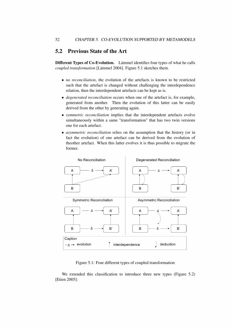
52 CHAPTER 5. CO-EVOLUTION SUPPORTED BY METAMODELS
5.2 Previous State of the Art
Different Types of Co-Evolution. Lämmel identifies four types of what he callscoupled transformation [Lämmel 2004]. Figure 5.1 sketches them.
• no reconciliation, the evolution of the artefacts is known to be restrictedsuch that the artefact is changed without challenging the interdependencerelation, then the interdependent artefacts can be kept as is.
• degenerated reconciliation occurs when one of the artefact is, for example,generated from another. Then the evolution of this latter can be easilyderived from the other by generating again.
• symmetric reconciliation implies that the interdependent artefacts evolvesimultaneously within a same "transformation" that has two twin versionsone for each artefact.
• asymmetric reconciliation relies on the assumption that the history (or infact the evolution) of one artefact can be derived from the evolution oftheother artefact. When this latter evolves it is thus possible to migrate theformer.
Figure 5.1: Four different types of coupled transformation
We extended this classification to introduce three new types (Figure 5.2)[Etien 2005]:

5.2. PREVIOUS STATE OF THE ART 53
• independence, the different artefacts independently evolve, potentially im-pacting the interdependence. This latter is eventually checked, for examplewith metrics, to be re-established.
• dependence is a subclass of asymmetric reconciliation when it is always thesame artefact that master the migration of the other. It is the most frequentcase of asymmetric reconciliation.
• double-dependence is also a subclass of asymmetric reconciliation. It corre-sponds to the case where each artefact can master at its turn the migration.
Figure 5.2: Three additional cases of co-evolution
Model-Metamodel Co-evolution. Model-metamodel co-evolution is a case ofdependence where the evolution of the metamodel may break the conformance ofthe existing models.
Rose et al. propose a classification of model migration approaches [Rose 2009].This classification highlights three ways to identify needed model updates: (i)manually, (ii) operator-based, and (iii) by inference. In manual approaches, mi-grations are defined by hand specifically to a given system [Rose 2010a]. In op-erator based, the metamodel changes are defined in terms of co-evolutionary op-erators [Herrmannsdoerfer 2009]. Those operators define conjointly the evolutionon the metamodel and its repercussions on the models. Finally, in inference ap-proaches, versions of metamodels are compared and differences between them areused to semi-automatically infer a transformation that expresses model updates[Garcés 2009, Cicchetti 2008].

54 CHAPTER 5. CO-EVOLUTION SUPPORTED BY METAMODELS
Transformation-Metamodel Co-evolution. Similarly to the previous case, trans-formation-metamodel co-evolution is a case of dependence where the evolution ofthe metamodel may break the interdependence with the transformations.
Steel et al. are aware that metamodel evolution might imply transformationmigration [Steel 2007]. However, they do not propose a transformation migra-tion approach. They define model typing that establishes the metamodel evolutionspectrum in which a transformation remains valid.
Roser et al. present an approach that enables semi-automatic transformationmigration after metamodel evolution [Roser 2008]. However, they only supportthe cases in that the source and target metamodels belong to the same knowledgearea represented by a reference ontology. The approach is thus not generic andadaptable to any transformation whatever the input and output metamodels.
Database Artefacts Co-evolution. Türker exposes the possible schema evolu-tions in SQL99 [Türker 2001]. In practice, a referenced artefact can not be re-moved since this evolution impacts the artefacts referencing it; only evolution withno impact on the existing artefacts (e.g. table, view, procedure) are allowed. Thus,for example, it is possible to remove a domain only if it is not referenced in any ofother entities. Database administrators have to manually ensure, before evolution,that it is possible.
Nagy et al. present a static technique for identifying the exact source codelocation in an object-oriented program from where a given SQL query was sent tothe database [Nagy 2015]. This query extraction approach is a first step for impactanalysis. Maule et al. analyze the impact of database schema changes on externalobject oriented program [Maule 2008]. The only entity types they take into accountare tables and columns; views, stocked procedures or triggers for example are nothandled. Database entities are used in a program only through queries that can bebuilt dynamically. They increase string analysis precision and reduce the parts ofthe program to which the analysis is applied with program slicing.
After having identified all possible atomic changes, Qiu et al. analyze thereal impacts caused by these atomic schema changes by mining a project’s versioncontrol history [Qiu 2013]. They use a database application’s co-change history toestimate the application code area affected by a schema change. Co-changes insidethe database schema are not taken into account.
Summary. There exists different types of co-evolution according to which en-tity evolves and how it is propagated to the other. However, each type relieson a strong relationship between the two co-evolving entities. In the context ofmodel driven engineering, model-metamodel co-evolution has been widely stud-ied, whereas transformation-metamodel co-evolution is only considered an issuewithout real solutions where the metamodel evolution may invalidate the trans-formation. In the context of traditional programs using database, co-evolution is

5.3. CONTRIBUTIONS 55
recognised as an issue. However, co-changes inside the database schema are notstudied.
5.3 Contributions
5.3.1 Transformation-Metamodel Co-evolution
Transformation-Metamodel Interdependence. We name the interdependencebetween transformations and metamodels domain conformance [Mendez 2010]and defined it as follows.
A precondition of transformations is that input models conform to source meta-model. The transformation has to guarantee that the generated output models con-form to target metamodel. As a consequence, the relationship between a trans-formation and its source metamodel is different from the relationship between thetransformation and its target metamodel. We call those relationships domain andcodomain respectively and define domain conformance in terms of them.
The domain of a transformation is the set of elements involved in the sourcepatterns (also called left hand side parts) of the transformation. Similarly, thecodomain of a transformation is the set of elements involved in the target patterns(also called right hand side parts) of the transformation. There is an additionalrestriction: models produced by the transformation should conform target meta-model.
A transformation T and its input and output metamodels (resp. MMin andMMout) respect the domain conformance relationship if the domain of T is a sub-metamodel1 of MMin, if the codomain of T is a submetamodel of MMout and ifall the well-formedness constraints defined in MMout concerning concepts presentin both MMout and the codomain of T also exist in the codomain of T .
Transformation Migration. Transformation migration can be split into threephases: 1) impact detection, 2) impact analysis, and 3) transformation adaptation.During impact detection, the transformation inconsistencies caused by metamodelevolution are identified i.e. where transformation does not satisfy domain con-formance. During impact analysis, the set of transformation updates needed tore-establish domain conformance is obtained possibly by using human assistance.Finally, during transformation adaptation, updates found in step two are applied.
In order to provide a solution independent of any platform and language, ourapproach relies on an abstract representation of the transformation also called Plat-form Independent Transformation (PIT) [Bézivin 2003], and a change metamodel.The change metamodel gathers all the changes that can occur on the source or
1in the sense of typing defined by Steel et al. in [Steel 2007]

56 CHAPTER 5. CO-EVOLUTION SUPPORTED BY METAMODELS
target metamodel elements such as Modify Multiplicity or EliminateInheritance
Impact analysis phase aims to identify the transformation updates needed to re-establish domain conformance. Our proposal relies on potential modifications. Thecurrent supported set is presented below. According to the kind of change appliedon the source or target metamodel elements and defined in the change metamodel,suggestions to update the transformation are proposed. Note that some changesmay need human intervention. Suggestions for a first set of changes occurring onthe metamodels associated to the transformation are listed below and were definedin [Mendez 2010].
• Rename Class/Property: All the occurrences of the renamed class/ pro-perty should be updated in the PIT model by changing its name.• Move Property: If this change occurs in the source metamodel, the path to
access the property should be updated in all statements involving it. If thechange occurs in the target metamodel, it is necessary to move the statementin the rule creating the new owner of the property and the path to access theother elements involved in the statement have to be updated.
If property is moved between classes that are in the same transformationpattern, then the path of the property should be updated.
• Modify Property: No suggestions in this case because it is impossible apriori to ensure the typing of property. Furthermore, in case of multiplicity,the management of a unique element may become a collection. The impactshould be resolved manually.• Introduce Class: Introducing a class in the source metamodel does not af-
fect domain conformance but metamodel coverage of transformation. Hence,the propagation of this change depends of the purpose of the transformationand cannot be automated.
Introducing a class in the target metamodel affects domain conformance onlyif this class is mandatory (i.e. referred with multiplicities “1”, “1..*”, “1..n”).This change cannot be automatically propagated. Hence, the user should doit manually by choosing one of two options: 1) write a new transformationrule that creates elements conform to the new class based on concepts ofsource metamodel and modify an existing rule to call the former. 2) modifythe target pattern of an existing transformation rule (mostly the one creatingthe owner of the added class) by including the new class on it.
• Introduce Property: The same analysis than class addition can be done ex-cept that statement and not rule are added. This statement should be eitherin the class containing the property or in its subclasses. If the property ismandatory (i.e. multiplicity: "1", "1..*", or "1..n") this action has to be done.• Replace Class: All the occurrences of the replaced class should be changed
by the new one. All the statements involving the properties of the replaced

5.3. CONTRIBUTIONS 57
class should be fixed manually by finding its equivalence in the new one.• Eliminate Class: If the removed class belonged to the target metamodel and
was the root of a pattern, the corresponding rule has to be removed. Other-wise, all the statements using the class or its properties should be removed. Ifafter that elimination some patterns become empty, the corresponding trans-formation rule should be eliminated.• Eliminate Property: All the statements involving the removed property
should be removed.• Introduce Inheritance: The same analysis than introduce property can be
done except that the mandatory inherited properties have to be included tothe transformation rules creating the subclasses if they not already exist inthe rule creating the super class.• Eliminate Inheritance: All the statements that involves inherited properties
by subclasses should be removed.
Researches around Transformation-Metamodel co-evolution took place in thecontext of David Mendèz’ internship, a master student that I supervised and a col-laboration with Professor Rubby Casallas from Universitad de los Andes, Bogota,Columbia.
5.3.2 Database and Program Co-Evolution.
An information system relies on a database gathering the data and a set of pro-grams treating these data. Two major approaches are adopted concerning the sep-aration between the database and the programs. Initially, data treatments wereimplemented as stocked procedures in the database management system. Such anapproach ensures the homogeneity of the data treatment whatever the applicationsusing the database. Due for example to the difficulty to debug SQL or stored proce-dure code or to the necessity for the developers to learn a new language, treatmentswere externalised in the application. However, information systems are no more asingle application on top of a database. Nowadays, they correspond to several ap-plications with different technologies and languages on top of the database. Suchnew database usages lead to clone code treatment between applications, increasemaintenance difficulty due for example to dynamic request, or inconsistencies be-tween database and program. To centralise treatments, ensure data coherence andincrease performances, information system engineers go back to stocked proce-dures usage and use advanced functionality like views or triggers.
During the last two years, based on the case study of the information system ofthe CRIStAL laboratory, I have been working on the co-evolution of the databasestructure and the database treatment embedded in the database management sys-tem. DB structure refers to tables, columns and integrity constraints. DB programcorresponds to code internally executed in the database system management andrelies on for example views, functions and triggers In this section, the co-evolution

58 CHAPTER 5. CO-EVOLUTION SUPPORTED BY METAMODELS
between the database structure and external program for example written in Php,Java or Pharo is not tackled.
Even if the data structure and the treatment are gathered into the database man-agement system, their co-evolution is not an easy task. None of the existing com-mercial tools that we tested helps in the co-evolution of entities belonging to thestructure or the program part of a same database schema2. Some of them enableto represent only tables and their dependencies (e.g. PgAdmin3 or Navicat4) otherdeal also with views (e.g. Toad5 or Maestro6) but none of them deal with functionsthat are only handled as strings.
Interdependence between Database Structure and Program. The relationsbetween database entities of the structure and the program internal to the databasemanagement system are classical Access/Reference or Invocation links. The com-plexity of the interdependence does not come under its type but under the differentuse cases of each entity by the others. All the links are gathered in a metamodelshown in Figure 5.3. Dark grey classes belong to the FAMIX metamodel. Theyare extended to build the SQL metamodel. Eight grey classes correspond to theconcepts composing the DB structure. White classes describe the DB internal pro-gram. An Expression is either a request, an invocation to a function or a column.A Request may content a select clause, a where clause, a from clause and otherclauses (e.g. order by or having). Each of these clauses are expressions. A re-quest can also refer tables in the from clause. A Function contains expressions.Consequently, a Column can be used by a View, a Function or another Column.This later case corresponds to the primary - foreign key link and belongs to theDB structure. The other cases correspond to link between structure and programentities. A Function can be called by a View, a Trigger, an other Function or ina Column definition, column belonging to a view (i.e., in the select clause of therequest composing the view). Finally, a Table can be used either in a Functionor a View definition in the from clause of a request. According to the databasemanagement system other entities are concerned by these links such as datatypes,sequences or aggregates for PostgreSQL. To simplify, we do not represent them inthe metamodel.
Impact Analysis between Database Structure and Program. Based on thisSQL/PL/pgSQL metamodel, it is possible to identify when an entity is used and inthe other way round which entities it uses. For this purpose, we developed an APIto query, from a given entity, all the dependent entities and all the used ones. This
2Database Schema = DB structure + DB internal program.3http://www.pgadmin.org4http://www.navicat.com5http://www.toadworld.com6https://www.sqlmaestro.com

5.3. CONTRIBUTIONS 59
Figure 5.3: SQL/PL/pgSQL Metamodel
API is independent of the entity type (e.g. Table, View, Function). This API allowsus to identify all the impacted entities when a given entity is changed.
The information system of CRIStAL, among others, manages the members ofthe laboratory according to the team they belong to, the financial support payingthem and keeps in memory the whole history. Thus, for example, the databaseregisters that I was in the Dart team as an Inria Post doc from September 2006 toAugust 2007. Then I was associate professor of normal class of Computer sciencein the same team from September 2007 until September 2012. Currently and sinceOctober 2012, I am associate professor in the RMod team. This concrete exampleshows that the database deals for example with person, support, team, rank (gradein French), employer. Based on this information for each member of the laboratory,thanks to functions and views, it is for example possible to foresee retirements bycomputing the ages pyramid or support ending.
Figure 5.4 illustrates an example of visualisation enabling the database admin-istrator to very quickly identify all the entities (e.g. tables, views, triggers andfunctions) that may be impacted if the personne table (in the centre of the butterflyvisualisation) is changed. It is possible (i) to work at the column level in order tohave an impact analysis at a finer grain than at table level as presented in the figureand (ii) to recursively apply the API in order to have in cascade impacts. Renamingor removing a column in this central table may directly impact around fifty entities(depending on the column), and even more by taking into account transitive impact.Indeed, in PostgreSQL, view structure can not be modified if other views depend

60 CHAPTER 5. CO-EVOLUTION SUPPORTED BY METAMODELS
on it. It has to be dropped and then create again in its new version. Manuallystudying such impacts in real case studies is quickly error prone and tedious.
Figure 5.4: All the entities using the personne table and which it uses
Moreover, we distinguish in the metamodel the different clauses of the request.The impacts won’t be the same according that the changed element appears in oneor the other clause. For example, removing a column appearing in the select clauseof request may be managed differently if this column is the only one appearing inthe select clause, if the request is used with a comparison operator like UNION orEXCEPT, or if the select clause refers several columns. In the two first cases, errorcan be raised. Similar analysis are possible for each type of changes occurring oneach DB structure type and for each relationship between entities. This analysiscorresponds to the one we did concerning transformation-metamodel co-evolution.It is part of future work.
This work on database structure and program co-evolution is in progress. Itrelies on a close collaboration with Olivier Auverlot, the architect of the CRIStALinformation system.

5.4. PERSPECTIVES 61
5.4 Perspectives
Transformation-Metamodel Co-evolution. Results concerning transformation-metamodel co-evolution were preliminary but precursory. Definitions of thechanges possibly occurring on the metamodels and their associated suggestionsneed to be further detailed. Moreover, the implementation of the suggested im-pacted changes remained a future work. Using a high order transformation, opera-tors, or specific strategy defined by the user were contemplated.
Even if research was undertaken on this topic, it seems that a realtransformation-metamodel co-evolution engine tackling models scalability is stillmissing. It should also be relevant to study the consequences of localised transfor-mation usage on transformation-metamodel co-evolution.
Unifying model-metamodel & transformation-metamodel co-evolution.Given the similarities between model-metamodel and transformation-metamodelco-evolution [Rose 2010b], it may be possible to use a single tool to manage bothtypes of co-evolution. Several potential advantages are apparent for a unifiedco-evolution approach. Firstly, the metamodel evolution is expressed only onceand enables the co-evolution of both models and transformations. Secondly,implementation of co-evolution tools may be simplified via the use of localisedtransformations. Thirdly, a unified approach may provide a foundation forsupporting other types of co-evolution, such as model-model (more commonlytermed model synchronisation). Given these advantages, future research shouldassess the extent to which co-evolution approaches can be unified, and compareunified and specialised approaches to establish their strengths and weaknesses.
Semi-Automatic database and program co-evolution. The last step of the data-base structure and program co-evolution is the migration of the program after achange in the structure. For this purpose, we first plan to provide migration rec-ommendations, to the database architect, for each impacted entities. These recom-mendations rely on the type of the involved entities, the link between them and theinitial change occurring on the entity. In a first time, they will be provided as plaintext. Adding, removing or renaming a Column for example will not have the sameimpacts. Possible changes on each entity type will be listed as a set of operatorsfor example by using the approach, we proposed [Rolland 2004]. In a second time,we plan to provide SQL code corresponding to the recommendations in order toperform the migration and resulting in a consistent and valid schema.
Database and DBMS external program co-evolution. The database structureand program co-evolution tackled in this chapter only concerns program embeddedin the Data Base Management System (DBMS) and more specifically functions

62 CHAPTER 5. CO-EVOLUTION SUPPORTED BY METAMODELS
written in PL/pgSQL or SQL. The state of the art has shown that others are provid-ing solutions for database structure and external program7 co-evolution. They onlytake into account the structure (i.e. Tables or Columns). We would like to enhancethese approaches by enabling the co-evolution when any schema entity i.e. alsoViews and Functions are used by external programs. Moreover, the existing ap-proaches often provide solutions when the program is written in Java. In CRIStALinformation system, Pharo programs are using database entities. We would like toprovide an approach independent as much as possible from the language used inthe program, by relying on metamodels.
7outside the DBMS

CHAPTER 6
Conclusion and Perspectives
This chapter first provides a summary of the contributions reported in the manu-script and then proposes short-term and long-term perspectives for the research inthis area.
6.1 Main Results
The results reported in this document aim to design systems of good quality andeasily maintainable and then maintain them. Two types of systems were studied:traditional programs and model transformation chains. Four phases of a systemlifecycle are analysed: design, architecture modifications, test and co-evolution.
Designing Model Transformation Chains. Model transformation chains weremonolithic and difficult to reuse and maintain. Based on our experience in theGaspard environnement we provided a new way to design model transformationsand chains: the localised transformations. Each transformation definition relieson small metamodels gathering only the concepts useful to it. The Extend op-erator enables the execution of the transformation on models conforming to largermetamodels. The in-place mechanism has been extended for transformation withdifferent input and output metamodels. This new way to design model transfor-mations has consequences on chains. Chain design is no more metamodel centricbut transformation centric. In other words, chains have to be specified in terms ofsuccessive steps to perform and no more in terms of intermediary states to reach.Localised transformations enable the definition of transformation libraries. We pro-vided mechanisms based on feature models to choose the adapted transformationsaccording to user’s requirements. New chaining constraints were also defined. TheGaspard environment was completely redesigned with localised transformations.In the same domain, adding a new chain from existing one for example to target anew language is easy and quick since lots of transformations can be reused. Thiswork is independent of the language used to specify the transformations. It resultsfrom collaborations. It has been published in international journals and conferencesand transferred to industry.
63

64 CHAPTER 6. CONCLUSION AND PERSPECTIVES
Software Architecture Modifications. Among the three different forms of soft-ware architecture modifications: refactoring, renovating and rearchitecting, weprovide concepts, methods and tools for two of them (refactoring and rearchitect-ing). Rearchitecting is performed to enhance software quality. We developed agraphical tool handling several possible alternative versions of the future architec-ture and enabling the developer to validate constraints on each of them. Conse-quently, with such a tool the better version can be chosen according to the wayeach version validates the constraints.
Repetitive sequences of operator changes were observed in the context of ar-chitecture refactoring or rearchitecting. These sequences slightly differ for eachapplication. We introduced the notion of transformation pattern and we provided atool to play and record once the sequence, to automatically configure it and play itagain in another context. The proposed approach is independent of the used pro-gramming language (patterns were observed in Java and PHARO programs). It relieson program and change operator abstractions. This work in the context of a PhDthesis and an international collaboration. It was the topic of several internationalpublications.
Testing Supported by Metamodels. Model transformations are used to gener-ate source code from models. Once defined, they are executed on multiple inputs.They have to be trustworthy to be sure that when an error is discovered in the gener-ated code, it results from an error in the input model and not one in the transforma-tion. Thus, as any other program, but also for this reason, model transformationshave to be tested. Existing tools and approaches for traditional programs cannotbe used as such and need to be adapted. We provided a traceability mechanismbased on two metamodels respectively dedicated to transformations and chains.This mechanism enables error localizations when outputs do not comply with theexpected ones. It has also been used in a mutation approach to qualify test set andcreate new test models when required. Once again these results are generic andindependent of the used transformation language.
When the tests are numerous, running all of them after a change in the programmay be very long, sometimes several hours. Consequently, the feedback to devel-opers is no more immediate, tests are only run at night. We are currently workingwith a major IT company to study the impact of the test case selection on the waydevelopers use tests. We compared static and dynamic approaches on three indus-trial projects. We identified some issues related to object-oriented paradigms andclassified them. This work on tests was conducted in the context of two PhD thesisand lead to industrial or academic collaborations.
Co-evolution Supported by Metamodels. Systems, in case of traditional pro-gram or model transformation chains, are composed of several interdependent arte-facts. When one of them evolves, others have to be consequently migrated to main-

6.2. PERSPECTIVES 65
tain the interdependence. We studied co-evolution in the context of metamodel andtransformation and also in the context of database schema and internal program.For this purpose, we have clearly specified the relationship between metamodel andtransformation. We also defined the relationships between Pg/PLSQL concepts.Recommendations to perform on the transformation after changes in the input orthe output metamodels are provided. Such recommendations for the database con-text do not yet exist but are part of future work. Currently, it is already possible toanalyse changes on elements of the database or the internal program and to identifytheir consequences on the internal program elements. Metamodel-transformationco-evolution has been generically treated by a master student whereas databaseschema-program is jointly studied with the administrator of the CRIStAL informa-tion system.
6.2 Perspectives
Definition of chains from on-the-shelves transformations. Designing transfor-mation chains remains difficult and long. Transformations and chains are oftenbuilt from scratch. Localised transformations have thrown the basis for the defini-tion of chains from on the shelves transformations. However, even if the proposedapproach is independent of used transformation language, we observed that it is do-main dependent. Introduction of genericity in transformation could help to reusetransformations from one domain to another.
Moreover, a strong knowledge of the domain is required to choose the neededtransformations and build the chains. Chaining constraints are taken into account,but non functional requirements should also be managed. This implies to providea language to express them, to check them and to mix them with already handledstructural constrains.
Finally, without a real tool enabling the developer to tune the input modeldirectly according to performance or execution expected on the generated code,transformation chains won’t be more used in industry. Feedbacks from the code onthe model are far to be immediate.
Tool Supported Architecture Modifications. Even with the tool we provided,architecture modifications are essentially manually performed directly on the code.They do not take benefit from models, contrarily to design. Or, in the opposite,they are undertaken at a very high level without real connection to the code. Ar-chitecture modifications require taking a step back and consequently, abstractionis useful. At the end, code is expected and since some pieces already exist, theyhave to be reused. These two abstraction levels should be accessible on demand.Moreover, architecture modifications are often done with a specific idea in mind,e.g., removing cycle, breaking large classes or decreasing coupling. It would be

66 CHAPTER 6. CONCLUSION AND PERSPECTIVES
good to be able to check if the goal is achieved as soon as possible and possiblytry several alternatives before choosing the best one. Some bricks already exist orwere proposed in this manuscrit. Nevertheless a complete approach is still missing.
Tool Supporting Co-evolution in the Large. Systems are composed of severalartefacts. Lehman has taught us that a software system must evolve, or it becomesprogressively less useful. We have seen that these evolutions may break interde-pendences between the artefacts. Co-evolution is a solution to this issue. However,it is currently mostly handled between two artefacts only. We provided exampleson metamodels and transformations and on database schema and programs. Thus,evolutions on the database schema lead for example to migrations of the program.But, these changes in the program may impact tests and documentations that willneed to evolve in cascade. Biologists distinguish co-evolution by pair where onlytwo species jointly evolve to diffuse co-evolution, when there are more species. Insoftware engineering, only this former type of co-evolution is managed whereas theother type is observed. Before jointly managing several artefacts, perhaps will it benecessary to easily adapt existing co-evolution mechanisms whatever the involvedartefacts.

Bibliography
[Alanen 2008] M. Alanen and I. Porres. A metamodeling language supportingsubset and union properties. Software and System Modeling, vol. 7, no. 1,pages 103–124, 2008.
[Aranega 2009] Vincent Aranega, Jean-Marie Mottu, Anne Etien and Jean-LucDekeyser. Traceability Mechanism for Error Localization in Model Trans-formation. In ICSOFT, Bulgaria, July 2009.
[Aranega 2011] Vincent Aranega, Jean-Marie Mottu, Anne Etien and Jean-LucDekeyser. Using Trace to Situate Errors in Model Transformations. InJosé Cordeiro, AlpeshKumar Ranchordas and Boris Shishkov, editeurs,Software and Data Technologies, volume 50 of Communications in Com-puter and Information Science, pages 137–149. Springer Berlin Heidel-berg, 2011.
[Aranega 2012] Vincent Aranega, Anne Etien and Sebastien Mosser. Using Fea-ture Model to Build Model Transformation Chains. In Proceedings of the15th International Conference on Model Driven Engineering Languagesand Systems, MODELS’12, pages 562–578, Berlin, Heidelberg, 2012.Springer-Verlag.
[Aranega 2013] Vincent Aranega, Jean-Marie Mottu, Anne Etien, ThomasDegueule, Benoit Baudry and Jean-Luc Dekeyser. Annexe and Experi-mentation material. https://sites.google.com/site/mutationtesttransfo/, 2013.
[Aranega 2014a] Vincent Aranega, Antonio Wendell De Oliveira Rodrigues, AnneEtien, Frédéric Guyomarch and Jean-Luc Dekeyser. Integrating Profilinginto MDE Compilers. International Journal of Software Engineering &Applications (IJSEA), vol. 5, no. 4, page 20, July 2014.
[Aranega 2014b] Vincent Aranega, Jean-Marie Mottu, Anne Etien, ThomasDegueule, Benoit Baudry and Jean-Luc Dekeyser. Towards an Automa-tion of the Mutation Analysis Dedicated to Model Transformation. Soft-ware Testing, Verification and Reliability, vol. 25, no. 5-7, pages 653–683,August-November 2014.
[Avgeriou 2013] Paris Avgeriou, Michael Stal and Rich Hilliard. Architecture Sus-tainability. IEEE Software, vol. 30, no. 6, pages 40–44, 2013.
[Baroni 2014] Alessandro Baroni, Henry Muccini, Ivano Malavolta and EoinWoods. Architecture Description Leveraging Model Driven Engineeringand Semantic Wikis. In 11th Conference on Software Architecture, pages251–254, 2014.
67

68 BIBLIOGRAPHY
[Baudry 2005] Benoit Baudry, Franck Fleurey, Jean-Marc Jézéquel and YvesLe Traon. From Genetic to Bacteriological Algorithms for Mutation-BasedTesting. STVR Journal, vol. 15, no. 2, pages 73–96, June 2005.
[Beck 2004] Kent Beck and Cynthia Andres. Extreme programming explained:Embrace change (2nd edition). Addison-Wesley Professional, 2004.
[Bézivin 2003] Jean Bézivin, Nicolas Farcet, Jean-Marc Jézéquel, Benoît Langloisand Damien Pollet. Reflective Model Driven Engineering. In G. BoochP. Stevens J. Whittle, editeur, Proceedings of UML 2003, volume 2863 ofLNCS, pages 175–189, San Francisco, October 2003. Springer.
[Biswas 2011] Swarnendu Biswas, Rajib Mall, Manoranjan Satpathy and SrihariSukumaran. Regression Test Selection Techniques: A Survey. Informatica(03505596), vol. 35, no. 3, 2011.
[Budgen 2003] David Budgen. Software design. Addison-Wesley Longman Pub-lishing Co., Inc., Boston, MA, USA, 2 édition, 2003.
[Cicchetti 2008] A. Cicchetti, D. Di Ruscio, R. Eramo and A. Pierantonio. Au-tomating Co-evolution in MDE. In Proc. EDOC, pages 222–231. IEEEComputer Society, 2008.
[Cordy 2009] Jim Cordy. Eating our own Dog Food: DSLs for Generative andTransformational Engineering. In GPCE, 2009.
[Cuadrado 2011] Jesús Sánchez Cuadrado, Esther Guerra and Juan de Lara.Generic Model Transformations: Write Once, Reuse Everywhere. In JordiCabot and Eelco Visser, editeurs, ICMT, International Conference on The-ory and Practice of Model Transformations, volume 6707 of Lecture Notesin Computer Science, pages 62–77. Springer, 2011.
[Czarnecki 2003] Krzysztof Czarnecki and Simon Helsen. Classification of ModelTransformation Approaches. Proceedings of the 2nd OOPSLA Workshopon Generative Techniques in the Context of the Model Driven Architecture,2003.
[de Lara 2012] Juan de Lara and Esther Guerra. Reusable Graph TransformationTemplates. In AGTIVE, volume 7233 of Lecture Notes in Computer Sci-ence, pages 35–50. Springer, 2012.
[DeMillo 1978] R. A. DeMillo, R. J. Lipton and F. G. Sayward. Hints on TestData Selection: Help for the Practicing Programmer. Computer, vol. 11,no. 4, pages 34–41, April 1978.
[dic ] Definition of Pattern by Merriam-Webster dictionary. http://www.
merriam-webster.com/dictionary/pattern. Accessed: 2015-06-30.

BIBLIOGRAPHY 69
[Ducasse 2000] Stéphane Ducasse, Michele Lanza and Sander Tichelaar. Moose:an Extensible Language-Independent Environment for ReengineeringObject-Oriented Systems. In Proceedings of the 2nd International Sympo-sium on Constructing Software Engineering Tools, CoSET ’00, June 2000.
[Ducasse 2011] Stéphane Ducasse, Nicolas Anquetil, Muhammad Usman Bhatti,Andre Cavalcante Hora, Jannik Laval and Tudor Girba. MSE and FAMIX3.0: an Interexchange Format and Source Code Model Family. Researchreport, Inria, 2011.
[Ehrig 2009] Karsten Ehrig, Jochen M. Küster and Gabriele Taentzer. Generatinginstance models from meta models. Software & Systems Modeling, vol. 8,no. 4, pages 479–500, 2009.
[Elbaum 2003] S. Elbaum, P. Kallakuri, A. G. Malishevsky, G. Rothermel andS. Kanduri. Understanding the effects of changes on the cost-effectivenessof regression testing techniques. Journal of Software Testing, Verification,and Reliability, 2003.
[Engström 2008] Emelie Engström, Mats Skoglund and Per Runeson. Empiricalevaluations of regression test selection techniques: a systematic review. InProceedings of the Second ACM-IEEE international symposium on Em-pirical software engineering and measurement, pages 22–31. ACM, 2008.
[Engström 2010] Emelie Engström, Per Runeson and Mats Skoglund. A system-atic review on regression test selection techniques. Information and Soft-ware Technology, vol. 52, no. 1, pages 14–30, 2010.
[Ernst 2003] Michael D Ernst. Static and dynamic analysis: Synergy and duality.In WODA 2003: ICSE Workshop on Dynamic Analysis, pages 24–27.Citeseer, 2003.
[Etien 2005] A. Etien and C. Salinesi. Managing requirements in a co-evolutioncontext. In Requirements Engineering, 2005. Proceedings. 13th IEEE In-ternational Conference on, pages 125–134, Aug 2005.
[Etien 2010] A. Etien, A. Muller, T. Legrand and X. Blanc. Combining Indepen-dent Model Transformations. In Proceedings of the ACM SAC, SoftwareEngineering Track, pages pp. 2239–2345, 2010.
[Etien 2012] Anne Etien, Vincent Aranega, Xavier Blanc and Richard F. Paige.Chaining Model Transformations. In Proceedings of the First Workshopon the Analysis of Model Transformations, AMT ’12, pages 9–14, NewYork, NY, USA, 2012. ACM.
[Etien 2015] Anne Etien, Alexis Muller, Thomas Legrand and RichardF. Paige.Localized model transformations for building large-scale transformations.Software & Systems Modeling, vol. 14, no. 3, pages 1189–1213, 2015.

70 BIBLIOGRAPHY
[Fleurey 2004] F. Fleurey, J. Steel and B. Baudry. Validation in model-driven engi-neering: testing model transformations. In Proceedings of MoDeVa, pages29–40, Nov. 2004.
[Fleurey 2009] Franck Fleurey, Benoit Baudry, Pierre-Alain Muller and Yves LeTraon. Qualifying input test data for model transformations. Software andSystem Modeling, vol. 8, no. 2, 2009.
[Fluri 2007] Beat Fluri, Michael Wuersch, Martin PInzger and Harald Gall.Change Distilling: Tree Differencing for Fine-Grained Source CodeChange Extraction. IEEE Transactions on Software Engineering, vol. 33,no. 11, pages 725–743, 2007.
[Fluri 2008] Beat Fluri, Emanuel Giger and Harald Gall. Discovering Patterns ofChange Types. In 23rd International Conference on Automated SoftwareEngineering, pages 463–466, 2008.
[Fowler 1999] Martin Fowler, Kent Beck, John Brant, William Opdyke and DonRoberts. Refactoring: Improving the design of existing code. Addison-Wesley, 1999.
[France 2003] Robert France, Sudipto Ghosh, Eunjee Song and Dae-Kyoo Kim. AMetamodeling Approach to Pattern-Based Model Refactoring. IEEE Soft-ware, vol. 20, no. 5, pages 52–58, 2003.
[Fraser 2010] Gordon Fraser and Andreas Zeller. Mutation-driven generation ofunit tests and oracles. In Proceedings of the 19th international symposiumon Software testing and analysis, ISSTA ’10, pages 147–158, New York,NY, USA, 2010. ACM.
[Fraser 2011] Gordon Fraser and Andrea Arcuri. EvoSuite: automatic test suitegeneration for object-oriented software. In ACM SIGSOFT Symposiumon the Foundations of Software Engineering, SIGSOFT FSE, 2011.
[Fraternali 2009] Piero Fraternali and Massimo Tisi. Mutation Analysis for ModelTransformations in ATL. In International Workshop on Model Transforma-tion with ATL, Nantes, France, June 2009.
[Gamatié 2011] Abdoulaye Gamatié, Sébastien Le Beux, Éric Piel, Rabie Ben Ati-tallah, Anne Etien, Philippe Marquet and Jean-Luc Dekeyser. A Model-Driven Design Framework for Massively Parallel Embedded Systems.ACM Trans. Embed. Comput. Syst., vol. 10, no. 4, pages 39:1–39:36, No-vember 2011.
[Garcés 2009] K. Garcés, F. Jouault, P. Cointe and J. Bézivin. ManagingModel Adaptation by Precise Detection of Metamodel Changes. In Proc.ECMDA-FA, volume 5562 of LNCS, pages 34–49. Springer, 2009.

BIBLIOGRAPHY 71
[Glitia 2008] Flori Glitia, Anne Etien and Cedric Dumoulin. Traceability for anMDE Approach of Embedded System Conception. In ECMDA TraceabilityWorkshop, Germany, 2008.
[Guerra 2012] Esther Guerra. Specification-Driven Test Generation for ModelTransformations. In Zhenjiang Hu and Juan de Lara, editeurs, ICMT, vol-ume 7307 of Lecture Notes in Computer Science, pages 40–55. Springer,2012.
[Hemel 2008] Zef Hemel, Lennart C. L. Kats and Eelco Visser. Code Generationby Model Transformation. In Proceedings of the 1st international confer-ence on Theory and Practice of Model Transformations, ICMT’08, pages183–198, Berlin, Heidelberg, 2008. Springer-Verlag.
[Herrmannsdoerfer 2009] M. Herrmannsdoerfer, S. Benz and E. Juergens. COPE- Automating Coupled Evolution of Metamodels and Models. In Proc.ECOOP, volume 5653 of LNCS, pages 52–76. Springer, 2009.
[Hsia 1997] Pei Hsia, Xiaolin Li, David Chenho Kung, Chih-Tung Hsu, Liang Li,Yasufumi Toyoshima and Cris Chen. A technique for the selective reval-idation of OO software. Journal of Software Maintenance: Research andPractice, vol. 9, no. 4, pages 217–233, 1997.
[ISO 2006] ISO. International Standard – ISO/IEC 14764 IEEE Std 14764-2006.Rapport technique, ISO, 2006.
[Jackson 2002] Daniel Jackson. Alloy: A New Technology for Software Model-ling. In Proceedings of the 8th International Conference on Tools and Al-gorithms for the Construction and Analysis of Systems, TACAS ’02, 2002.
[Javed 2012] Muhammad Javed, Yalemisew Abgaz and Claus Pahl. CompositeOntology Change Operators and their Customizable Evolution Strategies.In Workshop on Knowledge Evolution and Ontology Dynamics, collocatedat 11th International Semantic Web Conference, pages 1–12, 2012.
[Jiang 2015] Qingtao Jiang, Xin Peng, Hai Wang, Zhenchang Xing and WenyunZhao. Summarizing Evolutionary Trajectory by Grouping and AggregatingRelevant Code Changes. In 22nd International Conference on SoftwareAnalysis, Evolution, and Reengineering, pages 1–10, 2015.
[Kim 2013] Miryung Kim, David Notkin, Dan Grossman and Gary Wilson Jr.Identifying and Summarizing Systematic Code Changes via Rule Inference.IEEE Transactions on Software Engineering, vol. 39, no. 1, pages 45–62,2013.
[Küster 2006] Jochen M. Küster and Mohamed Abd-El-Razik. Validation ofmodel transformations: first experiences using a white box approach. In

72 BIBLIOGRAPHY
Proceedings of the 2006 international conference on Models in softwareengineering, 2006.
[Lämmel 2004] R. Lämmel. Coupled Software Transformations. In First Interna-tional Workshop on Software Evolution Transformations, November 2004.
[Lano 2013] Kevin Lano and Shekoufeh Kolahdouz Rahimi. Optimising Model-transformations using Design Patterns. In 1st International Conferenceon Model-Driven Engineering and Software Development, pages 77–82,2013.
[Lehman 1980] Meir M. Lehman. Programs, life cycles, and laws of softwareevolution. Proc. IEEE, vol. 68, no. 9, pages 1060–1076, September 1980.
[Lingampally 2007] R. Lingampally, A. Gupta and P. Jalote. A Multipurpose CodeCoverage Tool for Java. In System Sciences, 2007. HICSS 2007. 40thAnnual Hawaii International Conference on, pages 261b–261b, jan 2007.
[Maule 2008] Andy Maule, Wolfgang Emmerich and David S. Rosenblum. Im-pact Analysis of Database Schema Changes. In In Proceedings of Inter-national Conference on Software Engineering (ICSE’08, pages 451–460,2008.
[Mendez 2010] David Mendez, Anne Etien, Alexis Muller and Rubby Casallas.Towards Transformation Migration After Metamodel Evolution. In Modeland Evolution Wokshop, Olso, Norway, October 2010.
[Mens 2005a] T. Mens, G. Taentzer and O. Runge. Detecting Structural Refactor-ing Conflicts Using Critical Pair Analysis. Electronic Notes in TheoreticalComputer Science, vol. 127, no. 3, pages 113–128, April 2005.
[Mens 2005b] T. Mens, M. Wermelinger, S. Ducasse, S. Demeyer, R. Hirschfeldand M. Jazayeri. Challenges in software evolution. In Principles of Soft-ware Evolution, Eighth International Workshop on, pages 13–22, Sept2005.
[Mens 2005c] Tom Mens, Krzysztof Czarnecki and Pieter Van Gorp. A Taxonomyof Model Transformations. In Language Engineering for Model-DrivenSoftware Development, 2005.
[Mens 2007] Tom Mens, Gabriele Taentzer and Olga Runge. Analysing Refac-toring Dependencies Using Graph Transformation. Software and SystemsModeling, vol. 6, no. 3, pages 269–285, 2007.
[Mikkonen 1998] Tommi Mikkonen. Formalizing Design Patterns. In 20th Inter-national Conference on Software Engineering, pages 115–124, 1998.

BIBLIOGRAPHY 73
[Mottu 2006] Jean-Marie Mottu, Benoit Baudry and Yves Le Traon. MutationAnalysis Testing for Model Transformations. In ECMDA 06, Spain, July2006.
[Murphy-Hill 2009] Emerson Murphy-Hill, Chris Parnin and Andrew P. Black.How We Refactor, and How We Know It. In 31st International Conferenceon Software Engineering, pages 287–297, 2009.
[Nagy 2015] Csaba Nagy, Loup Meurice and Anthony Cleve. Where was thisSQL query executed? a static concept location approach. In Yann-GaëlGuéhéneuc, Bram Adams and Alexander Serebrenik, editeurs, Proceedingsof the 22nd International Conference on Software Analysis, Evolution andReengineering, pages 580–584. IEEE, 2015.
[Negara 2013] Stas Negara, Nicholas Chen, Mohsen Vakilian, Ralph E. Johnsonand Danny Dig. A Comparative Study of Manual and Automated Refac-torings. In 27th European Conference on Object-Oriented Programming,pages 552–576, 2013.
[Nguyen 2010] Tung Thanh Nguyen, Hoan Anh Nguyen, Nam H. Pham, JafarAl-Kofahi and Tien N. Nguyen. Recurring Bug Fixes in Object-orientedPrograms. In 32nd International Conference on Software Engineering,pages 315–324, 2010.
[Nguyen 2013] Hoan Anh Nguyen, Anh Tuan Nguyen, Tung Thanh Nguyen, T.N.Nguyen and H. Rajan. A study of repetitiveness of code changes in soft-ware evolution. In 28th International Conference on Automated SoftwareEngineering, pages 180–190, 2013.
[Oldevik 2005] Jon Oldevik. Transformation Composition Modelling Framework.In Proceedings of the Distributed Applications and Interoperable SystemsConference, volume 3543 of Lecture Notes in Computer Science, pages108–114. Springer, 2005.
[Olsen 2006] G. Olsen, J. Aagedal and J. Oldevik. Aspects of Reusable ModelTransformations. In Proceedings of the ECMDA Composition of ModelTransformations Workshop, pages pp. 21–26, 2006.
[Pigoski 1997] T. Pigoski. Practical software maintenance. best practices manag-ing your software investment. John Wiley and Sons, 1997.
[Pilgrim 2008] Jens Pilgrim, Bert Vanhooff, Immo Schulz-Gerlach and YolandeBerbers. Constructing and Visualizing Transformation Chains. InECMDA-FA ’08: Proceedings of the 4th European conference on ModelDriven Architecture, pages 17–32, Berlin, Heidelberg, 2008. Springer-Verlag.

74 BIBLIOGRAPHY
[Qiu 2013] Dong Qiu, Bixin Li and Zhendong Su. An Empirical Analysis of theCo-evolution of Schema and Code in Database Applications. In Proceed-ings of the 2013 9th Joint Meeting on Foundations of Software Engineer-ing, ESEC/FSE 2013, pages 125–135, New York, NY, USA, 2013. ACM.
[Ray 2012] Baishakhi Ray and Miryung Kim. A Case Study of Cross-system Port-ing in Forked Projects. In 20th International Symposium on the Founda-tions of Software Engineering, pages 1–11, 2012.
[Richa 2015] Elie Richa. Qualification of Source Code Generators in the AvionicsDomain : Automated Testing of Model Transformation Chains. PhD thesis,TELECOM ParisTech, 2015.
[Rivera 2009] José E. Rivera, Daniel Ruiz-Gonzalez, Fernando Lopez-Romero,José Bautista and Antonio Vallecillo. Orchestrating ATL Model Transfor-mations. In Proc. of MtATL 2009, pages 34–46, Nantes, France, July 2009.
[Rolland 2004] Colette Rolland, Camille Salinesi and Anne Etien. Eliciting gapsin requirements change. Requir. Eng., vol. 9, no. 1, pages 1–15, 2004.
[Rose 2009] Louis M. Rose, Richard F. Paige, Dimitrios S. Kolovos and FionaA. C. Polack. An Analysis of Approaches to Model Migration. In Proc.Models and Evolution (MoDSE-MCCM) Workshop, 12th ACM/IEEE In-ternational Conference on Model Driven Engineering, Languages and Sys-tems, October 2009.
[Rose 2010a] L.M. Rose, D.S. Kolovos, R.F. Paige and F.A.C. Polack. ModelMigration with Epsilon Flock. In Laurence Tratt and Martin Gogolla, edi-teurs, Theory and Practice of Model Transformations, Third InternationalConference, ICMT 2010, Malaga, Spain, June 28-July 2, 2010. Proceed-ings, volume 6142 of Lecture Notes in Computer Science, pages 184–198.Springer, 2010.
[Rose 2010b] Louis Rose, Anne Etien, David Mendez, Dimitrios Kolovos,Fiona Polack and Richard F. Paige. Comparing Model-Metamodel andTransformation-Metamodel Co-evolution. In Model and Evolution Wok-shop, Olso, Norway, October 2010.
[Roser 2008] Stephan Roser and Bernhard Bauer. Automatic Generation and Evo-lution of Model Transformations Using Ontology Engineering Space. Jour-nal on Data Semantics XI, pages 32–64, 2008.
[Rothermel 1993] Gregg Rothermel and Mary Jean Harrold. A Safe, Efficient Al-gorithm for Regression Test Selection. In Proceedings of the InternationalConference on Software Maintenance (ICSM ’93), pages 358–367. IEEE,September 1993.

BIBLIOGRAPHY 75
[Sanchez Cuadrado 2008] J. Sanchez Cuadrado and J. Garcia Molina. Approachesfor Model Transformation Reuse: Factorization and Composition. In Pro-ceedings of the International Conference on Model Transformation, vol-ume 5063 of LNCS, pages pp. 168–182. Springer-Verlag, 2008.
[Santos 2015a] Gustavo Santos, Nicolas Anquetil, Anne Etien, Stéphane Ducasseand Marco Tulio Valente. OrionPlanning: Improving modularization andchecking consistency on software architecture. In 3rd IEEE Working Con-ference on Software Visualization, VISSOFT 2015, Bremen, Germany,September 27-28, 2015, pages 190–194. IEEE, 2015.
[Santos 2015b] Gustavo Santos, Nicolas Anquetil, Anne Etien, Stephane Ducasseand Marco Tulio Valente. Recording and Replaying System Specific,Source Code Transformations. In 15th International Working Conferenceon Source Code Analysis and Manipulation, pages 221–230, 2015.
[Santos 2015c] Gustavo Santos, Nicolas Anquetil, Anne Etien, Stephane Ducasseand Marco Tulio Valente. System Specific, Source Code Transformations.In 31st International Conference on Software Maintenance and Evolution,pages 221–230, 2015.
[Seacord 2003] R.C. Seacord, D.A. PLAKOSH and G.A.A. LEWIS. Modernizinglegacy systems: Software technologies, engineering processes, and busi-ness practices. The SEI Series in Software Engineering. Addison WesleyPublishing Company Incorporated, 2003.
[Sen 2007] Sagar Sen, Benoit Baudry and Doina Precup. Partial Model Comple-tion in Model Driven Engineering using Constraint Logic Programming.In International Conference on the Applications of Declarative Program-ming, 2007.
[Sen 2008] Sagar Sen, Benoit Baudry and Jean-Marie Mottu. On CombiningMulti-formalism Knowledge to Select Models for Model TransformationTesting. In ICST., Norway, April 2008.
[Sen 2009] Sagar Sen, Naouel Moha, Benoit Baudry and Jean-Marc Jézéquel.Meta-model Pruning. In Andy Schürr and Bran Selic, editeurs, ModelDriven Engineering Languages and Systems, MODELS, volume 5795 ofLecture Notes in Computer Science. Springer, 2009.
[Sen 2012] Sagar Sen, Naouel Moha, Vincent Mahé, Olivier Barais, BenoitBaudry and Jean-Marc Jézéquel. Reusable model transformations. Soft-ware and System Modeling, vol. 11, no. 1, pages 111–125, 2012.
[Steel 2007] Jim Steel and Jean-Marc Jézéquel. On Model Typing. Journal ofSoftware and Systems Modeling (SoSyM), vol. 6, no. 4, pages 401–414,December 2007.

76 BIBLIOGRAPHY
[Terra 2012] Ricardo Terra, Marco Tulio Valente, Krzysztof Czarnecki andRoberto S. Bigonha. Recommending Refactorings to Reverse Software Ar-chitecture Erosion. In 16th European Conference on Software Maintenanceand Reengineering, pages 335–340, 2012.
[That 2012] Minh Tu Ton That, S. Sadou and F. Oquendo. Using ArchitecturalPatterns to Define Architectural Decisions. In Conference on SoftwareArchitecture and European Conference on Software Architecture, pages196–200, 2012.
[Tisi 2009] Massimo Tisi, Frédéric Jouault, Piero Fraternali, Stefano Ceri and JeanBézivin. On the Use of Higher-Order Model Transformations. In ModelDriven Architecture - Foundations and Applications, 5th European Confer-ence, 2009.
[Türker 2001] Can Türker. Schema Evolution in SQL-99 and Commercial (Object-)Relational DBMS. In Selected Papers from the 9th International Workshopon Foundations of Models and Languages for Data and Objects, DatabaseSchema Evolution and Meta-Modeling, FoMLaDO/DEMM 2000, pages1–32, London, UK, UK, 2001. Springer-Verlag.
[Vakilian 2013] Mohsen Vakilian, Nicholas Chen, Roshanak Zilouchian Moghad-dam, Stas Negara and Ralph E. Johnson. A Compositional Paradigm of Au-tomating Refactorings. In 27th European Conference on Object-OrientedProgramming, pages 527–551, 2013.
[van Amstel 2008] M. F. van Amstel, C. F. J. Lange and M. G. J. van den Brand.Metrics for Analyzing the Quality of Model Transformations. In 12thECOOP Workshop on Quantitative Approaches on Object Oriented Soft-ware Engineering, 2008.
[Vanhoof 2005] Bert Vanhoof and Yolande Berbers. Breaking up the transforma-tion chain. In Proceedings of the Best Practices for Model-Driven SoftwareDevelopment at OOPSLA 2005, San Diego, California, USA, 2005.
[Wagelaar 2009] Dennis Wagelaar, Ragnhild Van Der Straeten and Dirk Deridder.Module superimposition: a composition technique for rule-based modeltransformation languages. Software and Systems Modeling, 2009. OnlineFirst.
[White 1992] L.J. White and H.K.N. Leung. A firewall concept for both control-flow and data-flow in regression integration testing. In Software Mainte-nance, 1992. Proceedings., Conference on, pages 262–271, nov 1992.
[White 2005] L. White, K. Jaber and B. Robinson. Utilization of extended fire-wall for object-oriented regression testing. In Software Maintenance,2005. ICSM’05. Proceedings of the 21st IEEE International Conferenceon, pages 695–698, sep 2005.

BIBLIOGRAPHY 77
[Willmor 2005] D. Willmor and S.M. Embury. A safe regression test selectiontechnique for database-driven applications. In Software Maintenance,2005. ICSM’05. Proceedings of the 21st IEEE International Conferenceon, pages 421–430, sep 2005.
[Wimmer 2009] Manuel Wimmer, Angelika Kusel, Johannes Schönböck, GertiKappel, Werner Retschitzegger and Wieland Schwinger. Reviving QVTRelations: Model-Based Debugging Using Colored Petri Nets. In MoD-ELS, USA, 2009.
[Xanthakis 2000] S. Xanthakis, P. Régnier and C. Karapoulios. Le test des logi-ciels. Études et logiciels informatiques. Hermes Science Publications,2000.
[Ying 2004] Annie T. T. Ying, Gail C. Murphy, Raymond Ng and Mark C. Chu-Carroll. Predicting Source Code Changes by Mining Change History.IEEE Transactions on Software Engineering, vol. 30, no. 9, pages 574–586, 2004.
[Yoo 2012] S. Yoo and M. Harman. Regression testing minimization, selectionand prioritization: a survey. Software Testing, Verification and Reliability,vol. 22, no. 2, pages 67–120, 2012.
[Zaidman 2011] Andy Zaidman, Bart Van Rompaey, Arie van Deursen and SergeDemeyer. Studying the co-evolution of production and test code in opensource and industrial developer test processes through repository mining.Empirical Software Engineering, vol. 16, no. 3, pages 325–364, 2011.
[Zheng 2007] J. Zheng, L. Williams, B. Robinson and K. Smiley. Regression TestSelection for Black-box Dynamic Link Library Components. In Incorporat-ing COTS Software into Software Systems: Tools and Techniques, 2007.IWICSS ’07. Second International Workshop on, may 2007.