Metallographic Preparation of Tool Steels · 2020-01-25 · microstructural examination but there...
4
Solutions for Materials Preparation, Testing and Analysis By: George Vander Voort Metallographic Preparation of Tool Steels Published by Buehler, a division of Illinois Tool Works Volume 5, Issue 3 Tool steels are important materials and cover a wide range of compositions from simple plastic molding die steels or water- hardening carbon steels to very highly alloyed high-speed steels. Even more exotic compositions can be achieved by the powder metallurgy route. But, there are some common features. First, all are iron- based. Metallographers deal with relatively soft annealed tool steels, as-rolled or as-forged steels with a wide range of microstructural constituents and hardness, to heat-treated microstructures generally consisting of rather high strength martensite and a variety of carbide types. In tool and die failure analysis work, an even wider range of microstructures, some undesirable, can be encountered. In general, tool steels are not exceptionally difficult to prepare for microstructural examination but there are a number of problems to consider. First, sectioning can be rather difficult requiring weakly bonded abrasive blades to avoid burning. In preparing specimens, edge retention is often a requirement, for example, in the rating of decarburization or in the examination of heat-treated specimens, particularly those in failures. Inclusion retention may also be important, especially if the inclusion content must be rated. For graphitic tool steels, the graphite must be properly retained. Staining problems may be encountered, particularly in high silicon grades. Carbides may be cracked or there can be voids associated with carbides, particularly in the center of sections in high alloy grades. The metallographer must be able to determine if these voids are real, or produced by the preparation process. Preparation Procedures Sectioning Relatively soft specimens (less than 35 HRC or 345 HV) can be cut using band saws or hacksaws. However, such operations produce a substantial zone of deformation beneath the cut and rather rough surfaces. Thus, the initial rough grinding with a coarse abrasive (80- to 120-grit silicon carbide, for example) must remove this damage. Higher-hardness specimens must be cut using water-cooled abrasive cut-off wheels. The blade should have weak bonding for effective cutting and avoidance of burning. Submerged cutting limits heat generation, which is most severe when cutting as-quenched or quenched and lightly tempered tools steels. Heat generated by improper technique can produce a highly tempered appearance in the martensite and, if heating is excessive, can re-austenitize the surface. Subsequent grinding steps cannot easily remove this damage. When working with as-quenched high-alloy tool steels, it may be helpful to fracture the specimen. This will produce a flat, damage- free surface due to the brittleness of such steels. The fractured surface can then be ground and polished for examination. For high-hardness, high-alloy steels, sectioning with a diamond or cubic boron nitride wheel in a precision saw can provide high-quality surfaces with minimum damage. Although the cutting rate is low, such surfaces are smooth, and grinding can begin with rather fine grits (240- to 320-grit silicon carbide, for example). Mounting Bulk samples frequently can be polished without mounting. Most modern automatic polishing devices can handle unmounted specimens. If edge retention is important, mounting is necessary. Plating the surface prior to mounting produces optimum results, but is rarely necessary. The compression-mounting epoxy polymers, like EpoMet ® Resins, provide excellent edge retention even with unplated specimens. Automatic polishing devices rather than hand polishing yield better edge retention. Grinding and polishing in central force mode yields better flatness than single force mode. For small or oddly-shaped specimens, mounting is preferred. If the edge is not of particular interest, most mounting mediums are satisfactory. However, some mounts have poor resistance to solvents such as alcohol, and many are badly degraded if heated etchants are required. The compression-mounting epoxies prevent these problems. If a transparent mount is required to control grinding to a specific feature, transparent methyl methacrylate compression- mounting material can be used, and cast epoxies are also satisfactory. Castable epoxies are the only materials that produce true adhesive bonding to the sample. They also produce the lowest heat during curing and are useful when the sample cannot tolerate the higher heat used in compression mounting. When edge retention is not required and heat degradation is not anticipated, low-cost phenolic compression-molding materials can be used. The Traditonal Grinding and Polishing Approach In the traditional approach, either manual (hand polishing) or automated devices are used. Water-cooled silicon carbide paper (200- to 300-mm, or 8- to 12-inch diameter) is employed for the grinding stage; the ini tial grit size selected depends on the technique used to generate the cut surface. The usual grit sequence is 120, 240, 320, 400, and 600-grit. Finer grit sizes may be used for highly alloyed tools steels in which carbide pullout is a problem. Grinding pressure should be moderate to heavy, and grinding times of 1 to 2 minutes are typical to remove the scratches and deformation from the previous step. Fresh paper should be used;
Transcript of Metallographic Preparation of Tool Steels · 2020-01-25 · microstructural examination but there...
Solutions for Materials Preparation, Testing and Analysis
By: George Vander Voort
Metallographic Preparation of Tool Steels
Published by Buehler, a division of Illinois Tool Works Volume 5, Issue 3
Tool steels are important materials and cover a wide range of compositions from simple plastic molding die steels or water-hardening carbon steels to very highly alloyed high-speed steels. Even more exotic compositions can be achieved by the powder metallurgy route. But, there are some common features. First, all are iron-based. Metallographers deal with relatively soft annealed tool steels, as-rolled or as-forged steels with a wide range of microstructural constituents and hardness, to heat-treated microstructures generally consisting of rather high strength martensite and a variety of carbide types. In tool and die failure analysis work, an even wider range of microstructures, some undesirable, can be encountered.
In general, tool steels are not exceptionally difficult to prepare for microstructural examination but there are a number of problems to consider. First, sectioning can be rather difficult requiring weakly bonded abrasive blades to avoid burning. In preparing specimens, edge retention is often a requirement, for example, in the rating of decarburization or in the examination of heat-treated specimens, particularly those in failures. Inclusion retention may also be important, especially if the inclusion content must be rated. For graphitic tool steels, the graphite must be properly retained. Staining problems may be encountered, particularly in high silicon grades. Carbides may be cracked or there can be voids associated with carbides, particularly in the center of sections in high alloy grades. The metallographer must be able to determine if these voids are real, or produced by the preparation process.
Preparation Procedures SectioningRelatively soft specimens (less than 35 HRC or 345 HV) can be cut using band saws or hacksaws. However, such operations produce a substantial zone of deformation beneath the cut and rather roughsurfaces. Thus, the initial rough grinding with a coarse abrasive (80- to 120-grit silicon carbide, for example) must remove this damage.
Higher-hardness specimens must be cut using water-cooled abrasive cut-off wheels. The blade should have weak bonding for effective cutting and avoidance of burning. Submerged cutting limits heat generation, which is most severe when cutting as-quenched or quenched and lightly tempered tools steels. Heat generated by improper technique can produce a highly tempered appearance in the martensite and, if heating is excessive, can re-austenitize the surface. Subsequent grinding steps cannot easily remove this damage.
When working with as-quenched high-alloy tool steels, it may be
helpful to fracture the specimen. This will produce a flat, damage-free surface due to the brittleness of such steels. The fractured surface can then be ground and polished for examination. For high-hardness, high-alloy steels, sectioning with a diamond or cubic boron nitride wheel in a precision saw can provide high-qualitysurfaces with minimum damage. Although the cutting rate is low, such surfaces are smooth, and grinding can begin with rather fine grits (240- to 320-grit silicon carbide, for example).
Mounting Bulk samples frequently can be polished without mounting. Most modern automatic polishing devices can handle unmounted specimens. If edge retention is important, mounting is necessary. Plating the surface prior to mounting produces optimum results, but is rarely necessary. The compression-mounting epoxy polymers,like EpoMet® Resins, provide excellent edge retention even with unplated specimens. Automatic polishing devices rather than hand polishing yield better edge retention. Grinding and polishing in central force mode yields better flatness than single force mode.
For small or oddly-shaped specimens, mounting is preferred. If the edge is not of particular interest, most mounting mediums are satisfactory. However, some mounts have poor resistance to solvents such as alcohol, and many are badly degraded if heated etchants arerequired. The compression-mounting epoxies prevent these problems. If a transparent mount is required to control grinding to a specific feature, transparent methyl methacrylate compression-mounting material can be used, and cast epoxies are also satisfactory. Castable epoxies are the only materials that produce true adhesive bonding to the sample. They also produce the lowest heat during curing and are useful when the sample cannot tolerate the higher heat used in compression mounting. When edge retention is not required and heat degradation is not anticipated, low-cost phenolic compression-molding materials can be used.
The Traditonal Grinding and Polishing ApproachIn the traditional approach, either manual (hand polishing) or automated devices are used. Water-cooled silicon carbide paper (200- to 300-mm, or 8- to 12-inch diameter) is employed for the grinding stage; the ini tial grit size selected depends on the technique used to generate the cut surface. The usual grit sequence is 120, 240, 320, 400, and 600-grit. Finer grit sizes may be used for highly alloyed tools steels in which carbide pullout is a problem. Grinding pressure should be moderate to heavy, and grinding times of 1 to 2 minutes are typical to remove the scratches and deformation from the previous step. Fresh paper should be used;
Visit our website at www.buehler.com for more information.
worn or loaded paper will produce deformation.
In the traditional approach, polishing is commonly performed using one of more diamond abrasive stages followed by one or more final abrasive stages, generally with alumina abrasives. For routine work, polishing with 6- and 1-μm diamond is generally adequate. The diamond abrasive may be applied to the polishing cloth in paste orslurry form. For the coarser diamond abrasives, low-nap or napless cloths are preferred; a medium-nap cloth is generally used with the finer diamond abrasives. A lubricant, or “extender”, compatible with the diamond abrasive should be added to moisten the cloth and minimize drag. Wheel speeds of 100 to 150 rpm and moderate pressure should be used. Polishing times of ~2 minutes are usually adequate.
Final polishing can also be conducted manually or automatically using various devices. Alumina abrasives, generally 0.3-μm α-alumina (Al2O3) and 0.05-μm γ- Al2O3, are widely employed with medium-nap cloths for final polishing. Colloidal silica (SiO2), with a particle size range of 0.04- to 0.06-μm, is also very effective. Wheel speeds, pressure, and times are the same as for rough polishing with diamond abrasives. In general, tool steels are relatively easy to polish to a scratch-free and artifact-free condition due to their relatively high hardness.
Contemporary ApproachThe modern procedure utilizes automated equipment for grinding and polishing. The specimens are placed in a holder designed to accommodate a number of specimens of various sizes, mounted or unmounted. Either 200, 250 or 300mm (8, 10 or 12 inch) diameter formats may be employed. Newly developed surfaces and abrasivespermit achievement of surface qualities more than adequate for research work with as few as three steps.
Table 1 lists a four-step procedure that yields surfaces of a sufficient quality for any needs. For production work, step 4 could be omitted, yet the results will be quite satisfactory for routine examination. If step 4 is utilized, results are better and photographic work of publication quality is obtained.
Table 2 illustrates a simpler three-step procedure that also yields superb surfaces and research/publication quality micrographs. An UltraPad® Cloth may also be used for step 2, although the UltraPol® Silk Cloth produces the best results. With either surface, edge flatness is superb.
In complementary rotation the sample holder (head) is rotating in the same direction as the platen (normally counter clockwise) while in contra they rotate in opposite directions. Contra produces a somewhat greater removal rate. If the sample holder rotates at <100 rpm, the abrasive and lubricant will stay on the surface longer using contra. In complementary mode, centrifugal forces throw the liquids off the platen surface almost as quickly as it is added. However, if the head rotates at a speed >100 rpm, contra may throw the liquids all over the room. If relief patterns are observed around oxides or sulfides after step 4, simply repeat step 4 using complementary rotation and it will be removed. This happens rarely and is usually specimen specific in nature.
When charging the cloth with diamond, use paste as cutting is started faster. Apply a generous amount of diamond, and then spread the diamond with your clean fingertip. Apply the lubricant and start polishing. During the cycle, you can squirt on a diamond suspension, such as MetaDi® Supreme, with the same particle size as the paste to keep the cutting rate high. The slurries have the lubricant included, so you do not need to add additional MetaDi® Fluid lubricant, although some people do add small amounts occasionally even when using diamond in slurry form. MasterPrep® Alumina Suspension has a 0.05-μm alumina particle size and is made by the sol-gel process, rather than by the traditional calcination process, and is agglomerate free. If all these steps are followed, from cutting to polishing, the final step can be 5 minutes without introducing any relief or edge-rounding problems. Avoiding excessive cutting damage, mounting with EpoMet® Resin to avoid shrinkage gaps, starting grinding with the finest possible silicon carbide abrasive (or an equivalent sized abrasive in a different form, such as the DGD discs), and using contra rotation with a low head speed – these are the key steps to obtaining perfect renderings of the true microstructure.
EtchingThe etchant most widely used for tool steels is nital. Concentrations from 2 to 10% have been used. Generally, 2 or 3% nital is adequate
Table 1. Four-step method for preparing tool steels
Abrasive & Surface Lubricant RPM
Head Platen/
DirectionLoad per Specimen
Time (mins.)
120 to 240grit* (P120 to P280) SiC CarbiMet® 2 waterproof abrasive
paper, or 125 to45μm Apex® DGDs or
DGD Red or Purple
water 240- 300
Contra 6 lbs [27N] Until Plane
9-μm diamond on an UltraPol® silk cloth (orUltraPad® polyester
cloth or ApexHercules® H rigid grinding disc)
MetaDi® Fluid
120- 150
Contra 6 lbs [27N] 5
3-μm diamond on TriDent® cloth (or
TexMet® chemotextile pad)
MetaDi® Fluid
120- 150
Contra 6 lbs [27N] 3
MasterPrep® Alumina Suspension on a MicroCloth® pad
No other lubricant is needed
120- 150
Contra 6 lbs [27N] 1-3
* Use 120-grit for specimens > 60 HRC; use 180-grit for specimens at 35-60 HRC; use 240-grit for specimens < 35 HRC.
Table 2. Three-step method for preparing tool steels
Abrasive & Surface Lubricant RPM
Head Platen/
DirectionLoad per Specimen
Time (mins.)
120- to 240-grit* (P120 to P280)
SiC CarbiMet® 2 waterproof abrasive
paper, or 125 to45μmApex® DGDs or DGD Red or Purple
water 240- 300
Contra 6 lbs (27N) Until Plane
3-μm diamond on an UltraPol® silk cloth
cloth (or UltraPad® polyester cloth or
ApexHercules® H rigid grinding disc)
MetaDi® Fluid
120- 150
Contra 6 lbs (27N) 5
MasterPrep® Alumina Suspension on a MicroCloth® pad
No other lubricant is
needed
120- 150
Contra 6 lbs (27N) 5
* Use 120-grit for specimens > 60 HRC; use 180-grit for specimens at 35-60 HRC; use 240-grit for specimens < 35 HRC.
2
Visit our website at www.buehler.com for more information.
for most tool steels while a 10% concentration is required for highly alloyed tool steels, such as the D types. Stock solutions exceeding 3% HNO3 in ethanol should not be stored in pressure-tight bottles. If higher concentrations are desired as a stock reagent, a bottle with a pressure-relief valve should be used, or methanol should be substituted for ethanol. Methanol is a cumulative poison and its use should be minimized.
Nital is generally used for tool steels regardless of the anticipated microstructural constituents. Although nital is superior to picral (4% picric acid in ethanol) for etching martensitic structures, picral produces better results for examining annealed samples.
When examining spheroidize annealed tool steels (the most common annealed condition), picral reveals only the interfaces between carbide and ferrite. Nital also reveals the ferrite grain boundaries which generally obscurs the carbide shape. Also, because nital is orientation sensitive, carbides within some of the ferrite grains will be poorly delineated, making spheroidization ratings more difficult.
A 2% nital solution is usually preferred for martensitic steels. Stronger concentrations increase the speed of etching, making it more difficult to control. Etching of martensitic high-alloy tool steels, such as the high-speed steels, may require a 5% concentration, while the D types may require a 10% solution. Etching with nital or picral is usually performed by immersion. If swabbing is used, pressures should be light to avoid smearing problems.
Etching times are difficult to generalize, because of the wide range of tool steel compositions and because heat treatment can markedly alter etch response. Trial and error will determine the degree of surface dulling necessary to obtain the correct degree of etching.
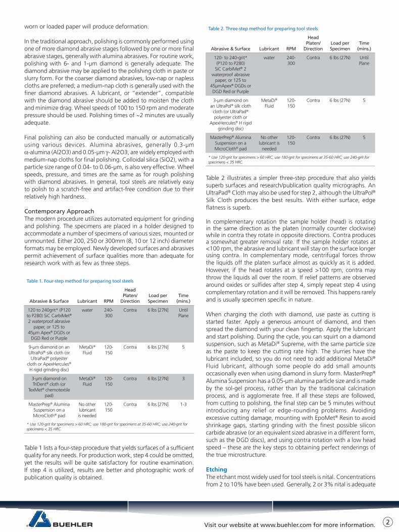
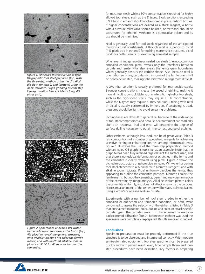
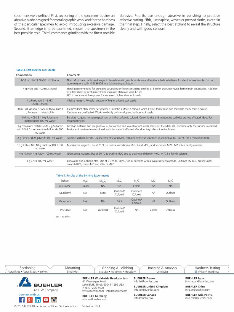
Other etchants, although less used, can be of great value. Table 3 lists compositions of a number of specialized reagents for achieving selective etching or enhancing contrast among microconstituents. Figure 1 illustrates the use of the three-step preparation method with annealed O6 graphitic tool steel as an example. Note that the graphite has been fully retained regardless of the surface used, and that there is no residual deformation or scratches in the ferrite and the cementite is clearly revealed using picral. Figure 2 shows the etched microstructure of spheroidize annealed W1 water hardening tool steel etched with 4% picral, with Klemm’s I reagent, and with alkaline sodium picrate. Picral uniformly dissolves the ferrite, thus appearing to outline the cementite particles. Klemm’s I colors the ferrite matrix, but not the cementite, permitting easy discrimination of the cementite by image analysis. Alkaline sodium picrate colors the cementite uniformly, and does not attack or enlarge the particles. Hence, measurements of the cementite will be statistically equivalent using Klemm’s or alkaline sodium picrate.
Experiments with a number of tool steel grades in either the annealed or quenched and tempered condition, or both, were conducted to assess the selectivity of the etchants listed in Table 3 that are claimed to outline, color, outline and color, or attack specific carbide types. The carbides were first characterized by electron-backscattered diffraction (EBSD). Before each etchant was used the specimens were completely re-prepared. Results are given in Table 4.
ConclusionsSpecimen preparation must be properly performed if the true structure is to be observed and interpreted correctly. With modern semi-automated equipment, tool steel specimens can be prepared quickly and with perfect results every time. Simple three- and four-step procedures have been described. Key factors in preparing
Figure 2. Spheroidize annealed W1 water-hardened carbon tool steel etched with (top) 4% picral to reveal the general structure, with (middle) Klemm’s I to color the ferritic matrix, and with (bottom) alkaline sodium picrate at 90 ºC for 60 seconds to color the cementite.
Figure 1. Annealed microstructure of type O6 graphitic tool steel prepared (top) with the three-step method using the UltraPol® silk cloth for step 2; and (bottom) using the ApexHercules® H rigid grinding disc for step 2 (magnification bars are 10-μm long; 4% picral etch).
3
BUEHLER Worldwide Headquarters41 Waukegan RoadLake Bluff, Illinois 60044-1699 USAP: (847) 295-6500www.buehler.com | [email protected]
BUEHLER [email protected]
BUEHLER [email protected]
BUEHLER United [email protected]
BUEHLER [email protected]
BUEHLER [email protected]
BUEHLER [email protected]
BUEHLER [email protected]
Connect with us:
© 2015 BUEHLER, a division of Illinois Tool Works Inc. Printed in U.S.A.
Table 4. Results of the Etching Experiments
Etchant M3C M23C6 M7C3 M6C MC M2C
Alk.Na Pic. Colors NA NA Colors NA NA
Murakami NA Faint Outlined/ Colored
Outlined/ Colored
NA Outlined
Groesbeck NA NA FaintOutlined/ Colored
NA Outlined
1% CrO3 NA OutlinedOutlined/ Colored
NA Colors Attacks
NA – no affect
Table 3. Etchants for Tool Steels
Composition Comments
1-10 mL HNO3 99-90 mL Ethanol Nital. Most commonly used reagent. Reveals ferrite grain boundaries and ferrite-carbide interfaces. Excellent for martensite. Do not store solutions with >3% HNO3 in a tightly stopped bottle.
4 g Picric acid 100 mL Ethanol Picral. Recommended for annealed structures or those containing pearlite or bainite. Does not reveal ferrite grain boundaries. Addition of a few drops of zephiran chloride increases etch rate. Add 1-5 mLHCl to improve etch response for annealed higher alloy tool steels.
1 g Picric acid 5 mL HCl95 mL Ethanol
Vilella’s reagent. Reveals structure of higher alloyed tool steels.
50 mL sat. Aqueous Sodium thiosulfate 1 g Potassium metabisulfite
Klemm’s I tint etch. Immerse specimen until the surface is colored violet. Colors ferrite blue and red while martensite is brown. Carbides are unaffected. Works well only on low alloy and carbon tool steels.
0.6 mL HCl 0.5-1.0 g Potassium metabisulfite 100 mL water
Beraha’s reagent. Immerse specimen until the surface is colored. Colors ferrite and martensite, carbides are not affected. Good for most tool steels.
3 g Potassium metabisulfite 2 g Sulfamic acid 0.5-1.0 g Ammonium bifluoride 100
mL water
Beraha’s sulfamic acid reagent No. 4. For carbon and low-alloy tool steels, leave out the NH4F•HF. Immerse until the surface is colored. Ferrite and martensite are colored; carbides are not affected. Good for high chromium tool steels.
2 g Picric acid 25 g NaOH 100 mL water Alkaline sodium picrate. Colors cementite and M6C carbides. Immerse specimen in solution at 80-100 °C for 1 minute or more.
10 g K3Fe(CN)6 10 g NaOH or KOH 100 mL water
Murakami’s reagent. Use at 20 °C to outline and darken M7C3 and M6C, and to outline M2C. M23C6 is faintly colored.
4 g KMnO4 4 g NaOH 100 mL water Groesbeck’s reagent. Use at 20 °C to outline M2C and to outline and darken M6C. M7C3 is faintly colored.
1 g CrO3 100 mL water Blickwede and Cohen’s etch. Use at 2-3 V dc, 20 °C, for 30 seconds with a stainless steel cathode. Outlines M23C6, outlines and colors M7C3, colors MC and attacks M2C.
specimens were defined. First, sectioning of the specimen requires anabrasive blade designed for metallographic work and for the hardness of the particular specimen to avoid introducing excessive damage. Second, if an edge is to be examined, mount the specimen in the best possible resin. Third, commence grinding with the finest possible
abrasive. Fourth, use enough abrasive in polishing to produce effective cutting. Fifth, use napless, woven or pressed cloths, except inthe final step. Finally, select the best etchant to reveal the structure clearly and with good contrast.