
Metallic GasketsMetallic Gaskets - Novus · PDF fileMetallic Gaskets 3 Selection Guide Many...
14
Metallic Gaskets
Transcript of Metallic GasketsMetallic Gaskets - Novus · PDF fileMetallic Gaskets 3 Selection Guide Many...
MetallicGasketsMetallicGaskets
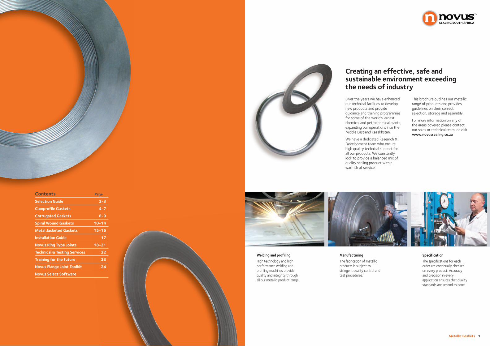
Welding and profiling
High technology and highperformance welding andprofiling machines providequality and integrity throughall our metallic product range.
Manufacturing
The fabrication of metallicproducts is subject tostringent quality control andtest procedures.
Specification
The specifications for eachorder are continually checkedon every product. Accuracyand precision in everyapplication ensures that qualitystandards are second to none.
Metallic Gaskets 1
Contents Page
Selection Guide 2-3
Camprofile Gaskets 4-7
Corrugated Gaskets 8-9
Spiral Wound Gaskets 10-14
Metal Jacketed Gaskets 15-16
Installation Guide 17
Novus Ring Type Joints 18-21
Technical & Testing Services 22
Training for the future 23
Novus Flange Joint Toolkit 24
Novus Select Software
Over the years we have enhancedour technical facilities to developnew products and provideguidance and training programmesfor some of the world's largestchemical and petrochemical plants,expanding our operations into theMiddle East and Kazakhstan.
We have a dedicated Research &Development team who ensurehigh quality technical support forall our products. We constantlylook to provide a balanced mix ofquality sealing product with awarmth of service.
This brochure outlines our metallicrange of products and providesguidelines on their correctselection, storage and assembly.
For more information on any ofthe areas covered please contactour sales or technical team, or visitwww.novusproducts.eu.
Creating an effective, safe andsustainable environment exceedingthe needs of industry

Metallic Gaskets 3
Selection Guide
Many factors affect thesuitability of a gasket in agiven application making itdifficult to determine whichis the correct one for theduty. In heat exchangerapplications, factors such as relative flange movementcan complicate gasketselection still further and it is important that theattributes of each gaskettype are fully understood.
To help you make aninformed choice on gasketselection the table below lists the advantages anddisadvantages of each gasketunder various conditions.
This table should be used as a general guide for selection only.
2 Metallic Gaskets
Camprofile GasketsCamprofile Gaskets consist of a metal core, generally stainlesssteel, with concentric grooves on either side. A sealing layer isnormally applied to both faces and depending on the service the material for this layer can be graphite, PTFE, Novus sheetmaterial, Hi-temp or metal (e.g. aluminium or silver).Camprofile gaskets are ideal forboth standard pipe and heatexchanger applications.
Corrugated GasketsCorrugated Metal Gaskets consist of a corrugated metalcore, normally stainless steel, with a soft facing layer applied to each face. The corrugationsprovide resilience and reduce thesealing surface area of the gasketwhile the soft layer ensuresoutstanding sealing, even at lowloads. Particularly suited as areplacement to metal jacketedgaskets.
Spiral Wound GasketsSpiral Wound Gaskets consist of a ‘V’ shaped metal strip spirallywound in combination with a softfiller material, normally graphite,PTFE or Hi-Temp. The metal stripprovides outstanding recoverywhilst the flexible filler ensuresexcellent sealing. Depending onthe application the gasket can bespecified with outer and/or innerrings.
Metal Jacketed GasketsMetal Jacketed Gaskets consist of soft filler material encapsulatedin a metallic material. The fillermaterial provides the gasket with compressibility and resiliencewhile the jacket conferscompressive strength and blow out resistance.
Ring Type JointsRing Type Joints are designed to concentrate the bolt load overa small area thus producing highseating stresses. As the ring typematerial should always be softerthan the mating flanges, the highseating stress causes ‘plastic-flow’ of the ring joint in the flange faces creating the seal.
TIGHTNESS EXCELLENT EXCELLENT
HANDLING EXCELLENT GOOD
THERMAL CYCLING EXCELLENT EXCELLENT
LOW SEATING STRESS EXCELLENT EXCELLENT
HIGH SEATING STRESS EXCELLENT GOOD
NARROW FLANGE WIDTH EXCELLENT AVERAGE
EMISSIONS EXCELLENT EXCELLENT
RECYCLING YES NO
EXCELLENT AVERAGE EXCELLENT
AVERAGE EXCELLENT EXCELLENT
GOOD AVERAGE AVERAGE
AVERAGE AVERAGE AVERAGE
EXCELLENT GOOD EXCELLENT
AVERAGE EXCELLENT AVERAGE
EXCELLENT AVERAGE EXCELLENT
NO NO NO

Metallic Gaskets 5
Camprofile Gaskets
4 Metallic Gaskets
M18LParallel root core with integral centering ring
M20LParallel root core without centeringring for male/female, tongue/groove and grooved flanges
M21LMParallel root core with floating centering ring attached outside the sealing ring
M38LConvex root core with integral centering ring
M40LConvex root core without centering ring for male/ female,tongue/groove and grooved flanges
M41LMConvex root core with floating centering ring, attached outside the sealing ring
GASKET PROFILESCore ThicknessCore thickness depends on theassembly circumstances. Generally a 3mm core is recommended but forlarge diameter gaskets above 1.5m it is advisable to use a 4mm core for purposes of stability.
Styles M21LM and M41LM areavailable in 4mm thickness only due to their construction.
M18, M20, M21 Advantages of parallel root cores
Uniform spread of stress at the cams.Uniform spread of stress across theflange surface.
M38, M40, M41Advantages of convex root cores
Highly suitable for underboltedflanges. Effective seal at low stress.The gasket design ensures a highseating stress area in the centre of the seal face and a lower seatingstress towards the outside edges of the seal face.
RECOMMENDED 3 Approx 3.1-3.4
>1.5m 4 ApproxM21LM 4.1-4.4M41LM
CORETHICKNESS (mm)
THICKNESS AFTER ASSEMBLY(core + layers)(mm)
Gasket ProfilesAll profiles feature as standard a 1mmcam pitch and a maximum groovedepth of 0.5mm. Alternative profilesare available on request e.g. 1.5mmcam pitch and a maximum groovedepth of 0.75mm (DIN profile).
Profile Selection
With or without centering ringCamprofile gaskets with centeringrings ensure optimum gasketpositioning between the bolts.
Loose or integral centering ringsThermal shock conditions maydamage camprofiles with integralcentering rings (thermal tension maycause cracks in the core). This isprevented by using camprofilegaskets with loose or floating guiderings.
The centering rings on styles M21LMand M41LM allow for expansion and contraction without reactionaryforces being applied to the core.
Optimal gasket performance isultimately ensured by the quality of flange surface finish and correctassembly.
Camprofile Gasket shapesIn addition to the round profiles,gaskets can be made in a variety ofshapes, oval, rectangular andexchanger with pass bars.
Correctly dimensioned gasketdrawings are required to make non-standard gaskets and gasket shapes.
Camprofile GasketCharacteristics
Camprofile gaskets consist of a metal core, generallystainless steel, with concentricgrooves on either side. A sealing layer is usuallyapplied on both sides anddepending on the service thematerial for this layer can begraphite, PTFE (Teflon), Novussheeting material, Hi-temp or metal (e.g. aluminium orsilver). Camprofiles can beused without sealing layersto provide an excellent sealbut there is a risk of flangesurface damage especially at high seating stresses. The sealing layers protect the flange surface fromdamage in addition toproviding an excellent seal at low bolt stress.
PropertiesCamprofiles have a number ofproperties which make themunique:
• Highly suitable for varyingtemperatures and pressures
• Less sensitive to assemblyfaults (inaccurate bolttightening)
• Suitable for light and heavydesigned flanges
• Dependent upon the layermaterial camprofile gasketscan resist temperatures up to1000OC
• Resistant to media pressures> 400 bar
• When assembled the remainingthickness of the sealing materialis extremely low (0.1 - 0.2mm),thus reducing leaks, fail ratesand environmental pollution
• The gasket will not damage theflange surface and can be easilyremoved
• Camprofile cores are re-usableafter cleaning, inspection andrelayering with new sealingmaterial. This is of particularinterest in the case of heatexchanger gaskets
• Reduces maintenance costs andleakage - thanks to camprofile’shigh sealing performance andreliability.
Seating Stress RangeThe camprofile gasket offers reliablesealing performance when seatedwithin the following seating stressranges. The below are based on parallel form gaskets. The values haveslight variations for convex forms ofcamprofiles.
Flange Surface FinishThe recommended flange surfacefinish for camprofiles with sealinglayers is from 3.2 to 6.3μm Ra (125-250 RMS), this is also referredto as a smooth finish.
GRAPHITE 20 90 400
PTFE 20 90 350
NOVUS SHEET 40 125 200
SILVER 125 240 450
HI-TEMP 40 100 250
LAYERMATERIAL
SEATING STRESS
MIN(N/mm2)
OPT(N/mm2)
MAX(N/mm2)

Metallic Gaskets 7
Camprofile Gaskets
6 Metallic Gaskets
Core Material Selection
Core MaterialThe core material is generallyfabricated in material identical to thepiping system to prevent corrosionproblems.
Stainless Steel 316L camprofilescores are generally used with carbonsteel pipe systems to prevent gasketcorrosion.
The recommended camprofile metalcores are shown in the table below.
Camprofile Gaskets M21L and M41LDuring recent years, modified gasketshave been introduced and these arenow included in our manufacturingprogramme.
Generally camprofile gaskets aremanufactured with a 0.5mm thickfloating centering ring. Based onintensive research and practical tests,in cooperation with major users, a1.5mm thick floating centering ringwas developed featuring a uniqueouter edge attachment.
The M21LM and M41LM stylesoffer the following advantages:
• The floating centering ring is stableand free from expansion stresses
• No distortion of the centering ringby the threads of the bolts, assometimes occurs in verticalassemblies, causing the camprofileto be positioned eccentrically.This also increases the possibilityof re-use, reducing costs
• User friendly - the 1.5mm thickguide ring reduces the risk ofoperator injury during handling
• The floating guide ring allowsfor expansion without applyingmechanical stress to the camprofilecore.
(1) Standard Material for Camprofile Gaskets
MATERIAL IDENTIFICATION DIN DIN B.S. AISA TEMPERATURE (oC) DENSITY(Trade name) SPECIFICATION MATERIAL ASTM MIN MAX (GR/CM2)
NO. UNS
Low Carbon Steel S R St 3.72 - - - -40 500 7.85
Stainless Steel 304 S304 X5 Cr Ni 18 1.4301 304S15/16/13 304 -250 550 7.90
Stainless Steel 304 L S304L X2 Cr Ni 18 9 1.4306 304S11 304L -250 550 7.90
Stainless Steel 309 S309 X15 Cr Ni Si 20 12 1.4828 309S24 309 -100 1000 7.90
Stainless Steel 316 S316 X5 Cr Ni Mo 18 10 1.4401 316S16 316 -100 550 7.90
Stainless Steel 316 L(1) S316L X2 Cr Ni Mo 18 10 1.4404 316S11/13 316L -100 550 7.90
Stainless Steel 316Ti 316Ti X10 Cr Ni Mo Ti 18 10 1.4571 320S31 316Ti -100 550 7.80
Stainless Steel 321 S321 X10 Cr Ni Ti 18 9 1.4541 321S12/49/87 321 -250 550 7.90
Stainless Steel 347 S347 X10 Cr Ni Nb 18 9 1.4550 347S31 347 -250 500 7.90
Stainless Steel 410 S410 X6 Cr 13 1.4000 410S21 410 -20 850 7.80
254SMO 6Mo X1 CrNiMoCu N2018 7 1.4547 - S31254 -100 500 8..00
Duplex 2205 X2 Cr Ni Mo N 22 5 3 1.4462 318S13 S31803/32205 -40 300 7.80
Super Duplex 2507 X2 Cr Ni Mo N 25 6 3 1.4410 - S32750 -40 300 7.80
Aluminium AL 1050 A1 99 5 3.0255 1B A91050 -250 300 2.71
Silver Ag - - - - -250 750 10.50
Copper Cu SF - Cu 2.0090 C106 C12200 -250 400 8.90
Nickel 200 Ni200 Ni 99 2 2.4066 3072-76 NA11 N02200 -250 600 8.90
Monel 400 400 Ni Cu 30 Fe 2.4360 3072-76 NA13 N04400 -125 600 8.80
Inconel 600 600 Ni Cr 15 Fe 2.4816 3072-76 NA14 N06600 -100 950 8.40
Inconel 625 625 Ni Cr 22 Mo 9 Mb 2.4856 3072-76 NA21 NO6625 -50 450 8.44
Incoloy 800 800 X10 Ni Cr A1 Ti 3220 1.4876 3072-76 NA15 N08800 -100 850 8.00
Incoloy 825 825 Ni Cr 21 Mo 2.4858 3072-76 NA16 N08825 -100 450 8.14
Hastelloy B2 B2 Ni Mo 28 2.4617 - N10665 -200 450 9.20
Hastelloy C276 C276 Ni Mo 16 Cr 15 W 2.4819 - N10276 -200 450 8.90
Titanium Ti2 Ti 99 8 3.7025 TA2 R50400 -250 350 4.50
Please specify the followingwhen ordering camprofilegaskets.
• Style of camprofile gasket
• Nominal pipe bore, pressurerating and flange standard
• Materials of core and sealinglayer
• For non standard flanges pleasespecify gasket dimensions.
EXAMPLE: The following example illustrateshow to order a camprofile gasket(information in bold print isstamped on the centering ring - if present; otherwise theinformation is printed on thepackaging):
M41LM – Style M41LM - convex root-form camprofile with floating externally attachedcentering ring
4”-300lbs – The gasket is suitablydimensioned for 4” flanges, 300lbspressure rating
316L – Camprofile core of 316Lstainless steel
Graphite – Graphite sealing layer
How to Order
Layer Material SelectionThe table above may be used todetermine the appropriate sealinglayer material. We recommend the use of graphite layers for mostapplications. Only in cases wheregraphite may cause mediacontamination, or is not chemicallyresistant, should an alternativematerial layer be chosen.
GraphiteGraphite is a universal, high quality,non asbestos sealing materialfeaturing:
• Very good chemical resistance• Resistance to high fluctuating
temperatures and pressures• Non ageing properties• Excellent gas tightness qualities.
Graphite APX 2Inhibited grade for oxidationresistance. Ideal for use attemperatures above the limitrecommended for standard graphitegrades. Often used in combinationwith Novus Hi-Temp for hightemperature applications.
LAYER TEMPERATURE (oC) MAXIMUM GAS APPLICATIONMATERIAL MIN MAX OPERATING TIGHTNESS
PRESSURE
Graphite -200 450 400 Good Aggressive Media
Graphite APX2 -200 500 400 Good Aggressive Media
PTFE -200 260 150 Good Aggressive Media
Novus Sheet -100 250 100 Good Moderate Media
Silver -200 750 250 Good Aggressive Media
Hi-Temp -200 1000 20 Average Gases
Hi-Temp + APX2 -200 800 100 Good Gases
HOW TO ORDER
PTFEPTFE is a high quality syntheticmaterial featuring:
• Excellent chemical resistance
• Temperature resistant up to260OC
• Good ageing resistance
• Excellent gas tightness.
Novus SheetNovus sheet materials consist ofsynthetic fibre compounds withrubber binders and material fillers.
SilverSilver is a precious metal combiningexcellent gas tightness and chemicalresistance properties. Generally usedin applications requiring gas tightnessat elevated temperatures.
Hi-TempHi-Temp is a mica-based materialsuitable for high temperatureapplications, often used incombination with graphite up to temperatures of 800oC.
LAYER TEMPERATURE (oC) MAXIMUM GAS APPLICATIONMATERIAL MIN MAX OPERATING TIGHTNESS
PRESSURE
Graphite -200 450 150 Good Aggressive Media
Graphite APX2 -200 500 150 Good Aggressive Media
PTFE -200 260 50 Good Aggressive Media
Hi-Temp + APX2 -200 800 100 Good Gases
Please specify the followingwhen ordering corrugatedgaskets.
• Standard of the gasket(flange standard)
• Nominal size and pressureclass
• Materials - core filler
EXAMPLE:
Novus CMGDimensions – ASME B16.202” 150lbsSS316 CoreGraphite coating layer
Corrugated Gaskets
Seating Stress RangeCorrugated gaskets offer reliablesealing performance when seatedwithin the following seating stressranges.
ThicknessAvailable in 1.5mm, 2mm and 3mm.
Flange Surface FinishThe recommended flange surfacefinish for corrugated gaskets withsealing layers is from 3.2 to 6.3μm Ra(125-250 RMS), this is also referredto as a smooth finish.
Sizing GuidelinesDIN Sizes 10, 16, 25, 40 bar.ANSI Sizes Class 150 and 300lb.Other sizes available on request. Alsoavailable for vessel and non-standardapplications.
Chemical SuitabilityPH Range 0-14.
20 90 200
SEATING STRESS (20oC)
MINIMUM(N/mm2)
OPTIMUM(N/mm2)
MAXIMUM(N/mm2)
Layer Material SelectionThe table (below) may be used todetermine the appropriate sealinglayer material. We recommend the use of graphite layers for mostapplications. Only in cases wheregraphite may cause mediacontamination, or is not chemicallyresistant, should an alternative layermaterial be chosen.
GraphiteGraphite is a universal, high quality,non asbestos sealing materialfeaturing very good chemicalresistance, resistance to high fluctuating temperatures andpressures, non ageing properties plus excellent gas tightness.
Graphite APX 2Inhibited grade for oxidationresistance. Ideal for use attemperatures above the limitrecommended for standard graphitegrades. Often used in combinationwith Novus Hi-Temp for hightemperature applications.
PTFEPTFE is a high quality syntheticmaterial featuring excellent chemicalresistance, temperature resistant upto 260OC, good ageing resistance1and excellent gas tightness.
Hi-TempHi-Temp is a mica based materialsuitable for high temperatureapplications, often used incombination with graphite upto temperatures of 800OC.
How to OrderHOW TO ORDER
8 Metallic Gaskets Metallic Gaskets 9
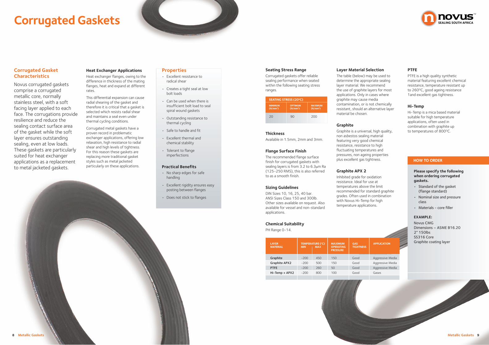
Corrugated GasketCharacteristics
Novus corrugated gasketscomprise a corrugatedmetallic core, normallystainless steel, with a softfacing layer applied to eachface. The corrugations provideresilience and reduce thesealing contact surface areaof the gasket while the softlayer ensures outstandingsealing, even at low loads.These gaskets are particularlysuited for heat exchangerapplications as a replacementto metal jacketed gaskets.
Properties• Excellent resistance to
radical shear
• Creates a tight seal at lowbolt loads
• Can be used when there isinsufficient bolt load to sealspiral wound gaskets
• Outstanding resistance tothermal cycling
• Safe to handle and fit
• Excellent thermal andchemical stability
• Tolerant to flangeimperfections
Practical Benefits• No sharp edges for safe
handling
• Excellent rigidity ensures easyposting between flanges
• Does not stick to flanges
Heat Exchanger ApplicationsHeat exchanger flanges, owing to thedifference in thickness of the matingflanges, heat and expand at differentrates.
This differential expansion can causeradial shearing of the gasket andtherefore it is critical that a gasket isselected which resists radial shearand maintains a seal even underthermal cycling conditions.
Corrugated metal gaskets have aproven record in problematicexchanger applications, offering lowrelaxation, high resistance to radialshear and high levels of tightness.For this reason these gaskets arereplacing more traditional gasketstyles such as metal jacketedparticularly on these applications.

Metallic Gaskets 11
Spiral Wound Gaskets
10 Metallic Gaskets
Gasket Stress RangeNovus spiral wound gaskets shouldpreferably be mounted within thegasket stress ranges shown in thischart to ensure leak free connections.
Flange Surface FinishThe recommended surface roughnessof the flange faces, between which aspiral wound gasket is to be mounted,is 3.2 - 6.3μm Ra (125 - 250 RMS),also referred to as smooth finish.
Standard Gasket ProfilesWe produce the following types of spiral wound gaskets.
Spiral Wound GasketCharacteristics
The sealing element of thespiral wound gasket consistsof a V-shaped metal stripspirally wound in combinationwith a soft sealing materialfiller. The metal strip providesoutstanding resilience, whilethe flexible sealing fillerguarantees excellent sealing.
Due to this combination ofmaterials, the spiral woundgasket is suitable for sealingunder severely fluctuatingtemperature and pressureconditions. Depending on theapplication the spiral woundgasket can be specified withouter and/or inner rings.
Properties• Spiral wound gaskets are
suitable for use across a widegasket stress range.
• Spiral Wound gaskets can beused to seal fluid pressures upto 400 bar and from cryogenictemperatures up to 1000OC.
• Spiral Wound gaskets arerobust and simple to install.
• The outer guide ring simplifiesassembly and prevents blow-out of the gasket.
• By combining different windingmaterials and metals, thegasket can be tailored to suita wide variety of operatingconditions.
• The gasket is easy to removeafter service and does notcause any damage to theflange faces.
SINGLE SIDE CONFINED BOTH SIDES CONFINED
FILLER GASKET STRESS (20oC) GASKET STRESS (20oC)
MIN OPT MAX MIN OPT MAX(N/mm2) (N/mm2) (N/mm2) (N/mm2) (N/mm2) (N/mm2)
Graphite 50 95 180 50 120 400
PTFE 50 80 130 50 110 250
Hi-Temp 55 95 130 50 120 250+ APX2
Gasket Stress Range:
Type SGThe standard spiral wound gasketformat identical to Novus RF1 butfitted with an outer centering ring(applied to raised face flanges).An integral centering guide ringensures fast, accurate centeringof the gasket on the flange.Provides additional radial strengthto prevent gasket blow-out andacts as a compression stop.
Type RF-IRSpiral wound gasket formale/female flangesconsisting of a woundcomponent fitted with aninner ring to bring the gasketflush with the pipe bore toprevent inward buckling.
Type SG-IRIdentical to Novus SG butalso fitted with an innerring to prevent inwardbuckling at the windings.
Type HX-RThis type of gasket consists of a wound component fitted with a narrow wound centering ring.Centering windings ensurecorrect centering in flush flanges(e.g. in heat exchangers).
Type RF1The gasket consists of a sealing filler and V-shapedmetal strip wound incombination. This profileis usually applied totongue/groove flanges.
Type SG-RTJA standard spiral woundgasket (SG Type) withdimensions tailored to Ring Joints (RTJ) flanges.
Type HX-RIRThis gasket is identical to HX-R but also fitted with an inner ring, rendering thisgasket type suitable formounting in male and femaleflanges.

Type WLThis gasket is identical to RF1 but fitted with an outer winding.Centering is achieved by positioningthe winding over two bolts oppositeeach other.
Type HEFitted with pass partition bars for useon heat exchangers and vessels, thisgasket type is otherwise identical tothe RF1 profile. Metal - jacketed barshave a thinner design than that ofspiral wound gasket material.
The bars are fixed through welding.
Type HE-SGFitted with an outer centering ring,the HE-SG is otherwise identical tothe HE profile.
Type HE/SG-IRFitted with an outer centering ringand an inner ring, the HE/SG-IR isotherwise identical to the HE profile.
Special ShapesSpiral wound gaskets can be producedin a wide variety of shapes, such asoval and pear-shape, with passpartition bars and many other types.Generally, the pass partition bars onspiral wound gaskets aremanufactured as metal-jacketed bars.A variety of alternatives are available.
Type MHThis spiral wound gasket is identical to the RF1 profile but oval shaped to fit manholes.
Type TC/HHThis type of gasket is for hand holesand special flange assemblies (tubecap and hand hole covers). They areavailable in square, rectangular, oval,diamond and pear shapes.A drawing specifying the correctdimensions are required tomanufacture special shapes.
Special Profiles
Profile with a GT - ZoneIn the event of a graphite filled spiralwound gasket possibly causing anundesirable reaction between thegraphite and the medium to besealed, or of possible mediumcontamination, the problem can besolved by using a spiral wound gasketwith a GT - Zone.
The spiral wound element of a NovusGT - Zone gasket consists of outerwindings of Hi-Temp material with acentral winding zone made ofgraphite or PTFE (depending on theoperating conditions) to improve gastightness. This results in a spiralwound gasket with the followingproperties:
• Can be used at highertemperatures
• Has excellent sealing properties
Combined with the other advantagesof a spiral wound gasket, the spiralwound with a GT - Zone may be usedin a wide range of operatingconditions and applications.
Metallic Gaskets 13
Spiral Wound Gaskets
12 Metallic Gaskets
Outer Winding
Spiral Gasket
Bolt Position
Guide Rings and Material Selection
Benefits of the Centering RingThe spiral wound gasket outer centeringring provides the following benefits:
• Optimum location between the bolts
• Protection of the spiral wound element
• Additional security against gasketblow-out
• Acts as compression limiter preventingoverloading and over compression ofthe spiral wound element
• Prevents radial-flow of soft fillers,1such as PTFE.
For these reasons it is preferable to usespiral wound gaskets with outer centeringrings.
The outer ring is marked with nominal size,pressure class, standard and materials.
Benefits of the Inner Ring The spiral gasket inner ringprovides the following benefits:
• Prevents radial-flow of softfillers, such as PTFE + Graphite
• Reduces turbulence-minimisingflow resistance
• Acts as a heat shield when thespiral wound gasket issubjected to high temperatures.
Inner and outer rings areparticularly recommended for useon spiral wound gaskets exceedingclass 600lbs, but specificallyrecommended for hightemperatures and pressures tooptimise the operational reliabilityof the spiral wound sealingelement. Inner rings are mandatoryfor PTFE filled spirals.
Material SelectionThe material selected for the innerring and winding metal is usuallythe same as the flange metal. Thisprevents corrosion and differentialexpansion problems. The outercentering ring is generallymanufactured from carbon steel with an anti- corrosion treatment.However, the ring may also bemanufactured in the same metal asthe flange to prevent corrosionproblems.
The table below lists the applicationlimits and specifications of alloysused in the manufacture of spiralwound gaskets.
MATERIAL IDENTIFICATION DIN DIN B.S. AISA TEMPERATURE (oC) DENSITY(TRADE NAME) SPECIFICATION MATERAIL ASTM MIN MAX (GR/CM2)
NO. UNS
Low Carbon Steel S R St 3.72 - - - -40 500 7.85
Stainless Steel 304 S304 X5 Cr Ni 18 1.4301 304S15/16/13 304 -250 550 7.90
Stainless Steel 304 L S304L X2 Cr Ni 18 9 1.4306 304S11 304L -250 550 7.90
Stainless Steel 309 S309 X15 Cr Ni Si 20 12 1.4828 309S24 309 -100 1000 7.90
Stainless Steel 316 S316 X5 Cr Ni Mo 18 10 1.4401 316S16 316 -100 550 7.90
Stainless Steel 316 L(1) S316L X2 Cr Ni Mo 18 10 1.4404 316S11/13 316L -100 550 7.90
Stainless Steel 316Ti 316Ti X10 Cr Ni Mo Ti 18 10 1.4571 320S31 316Ti -100 550 7.80
Stainless Steel 321 S321 X10 Cr Ni Ti 18 9 1.4541 321S12/49/87 321 -250 550 7.90
Stainless Steel 347 S347 X10 Cr Ni Nb 18 9 1.4550 347S31 347 -250 500 7.90
Stainless Steel 410 S410 X6 Cr 13 1.4000 410S21 410 -20 850 7.80
254SMO 6Mo X1 CrNiMoCuN 20187 1.4547 - S31254 -100 500 8.00
Duplex 2205 X2 Cr Ni Mo N 22 5 3 1.4462 318S13 S31803/32205 -40 300 7.80
Super Duplex 2507 X2 Cr Ni Mo N 25 6 3 1.4410 - S32750 -40 300 7.80
Aluminium AL 1050 A1 99 5 3.0255 1B A91050 -250 300 2.71
Nickel 200 Ni200 Ni 99 2 2.4066 3072-76 NA11 N02200 -250 600 8.90
Monel 400 400 Ni Cu 30 Fe 2.4360 3072-76 NA13 N04400 -125 600 8.80
Inconel 600 600 Ni Cr 15 Fe 2.4816 3072-76 NA14 N06600 -100 950 8.40
Inconel 625 625 Ni Cr 22 Mo 9 Mb 2.4856 3072-76 NA21 NO6625 -50 450 8.44
Incoloy 800 800 X10 Ni Cr A1 Ti 3220 1.4876 3072-76 NA15 N08800 -100 850 8.00
Incoloy 825 825 Ni Cr 21 Mo 2.4858 3072-76 NA16 N08825 -100 450 8.14
Hastelloy B2 B2 Ni Mo 28 2.4617 - N10665 -200 450 9.20
Hastelloy C276 C276 Ni Mo 16 Cr 15 W 2.4819 - N10276 -200 450 8.90
Titanium Ti2 Ti 99 8 3.7025 TA2 R50400 -250 350 4.50
Standard Material for Spiral Wound Windings
Metallic Gaskets 15
Spiral Wound Gaskets
14 Metallic Gaskets
Metal Jacketed Gaskets
Non standard materials are available on request
Filler Material Selection
The table opposite may be used toselect the correct filler. It should bepointed out that graphite will be theoptimum filler in most cases. Onlywhere graphite could cause mediacontamination, or is not chemicallyresistant, should the use of anothertype of filler material berecommended. In such cases, analternative solution might be toselect a gasket with a GT-zone.
GraphiteGraphite is universally chosenbecause of its good chemicalresistance, resistance to ageing,good gas tightness and ability tooperate at high temperatures.
APX2APX2 is an oxidation resistantgraphite which offers the sameexcellent sealing characteristics ofgraphite but can be used at higherservice temperatures.
LAYER TEMPERATURE (oC) MAXIMUM GAS APPLICATIONMATERIAL MIN MAX OPERATING TIGHTNESS
PRESSURE (BAR)
Graphite -200 450 400 Good Aggressive Media
Graphite APX2 -200 500 400 Good Aggressive Media
PTFE -200 260 150 Good Aggressive Media
Hi-Temp -200 1000 5 Average Gases
Hi-Temp + APX2 -200 800 100 Good Gases
Standard Fillers
Please specify the followingwhen ordering Spiral WoundGaskets.
• Type of Spiral woundgasket required
• Standard of the gasket(flange standard)
• Nominal size and pressureclass
• Material:- Inner ring- Metal winding- Filler- Outer ring
EXAMPLE:
Novus SG-IRDimensions – ASME B16.202” 150lbsSS316LSS316L GraphiteCarbon Steel
How to OrderHOW TO ORDERPTFEPTFE is a high quality syntheticmaterial with the followingcharacteristics: excellent chemicalresistance, resistance to 260OC,resistant to ageing, excellent gastightness.
Hi-TempHi-Temp is mica based materialsuitable for high temperatureapplications, often used incombination with graphite (GT-zone).
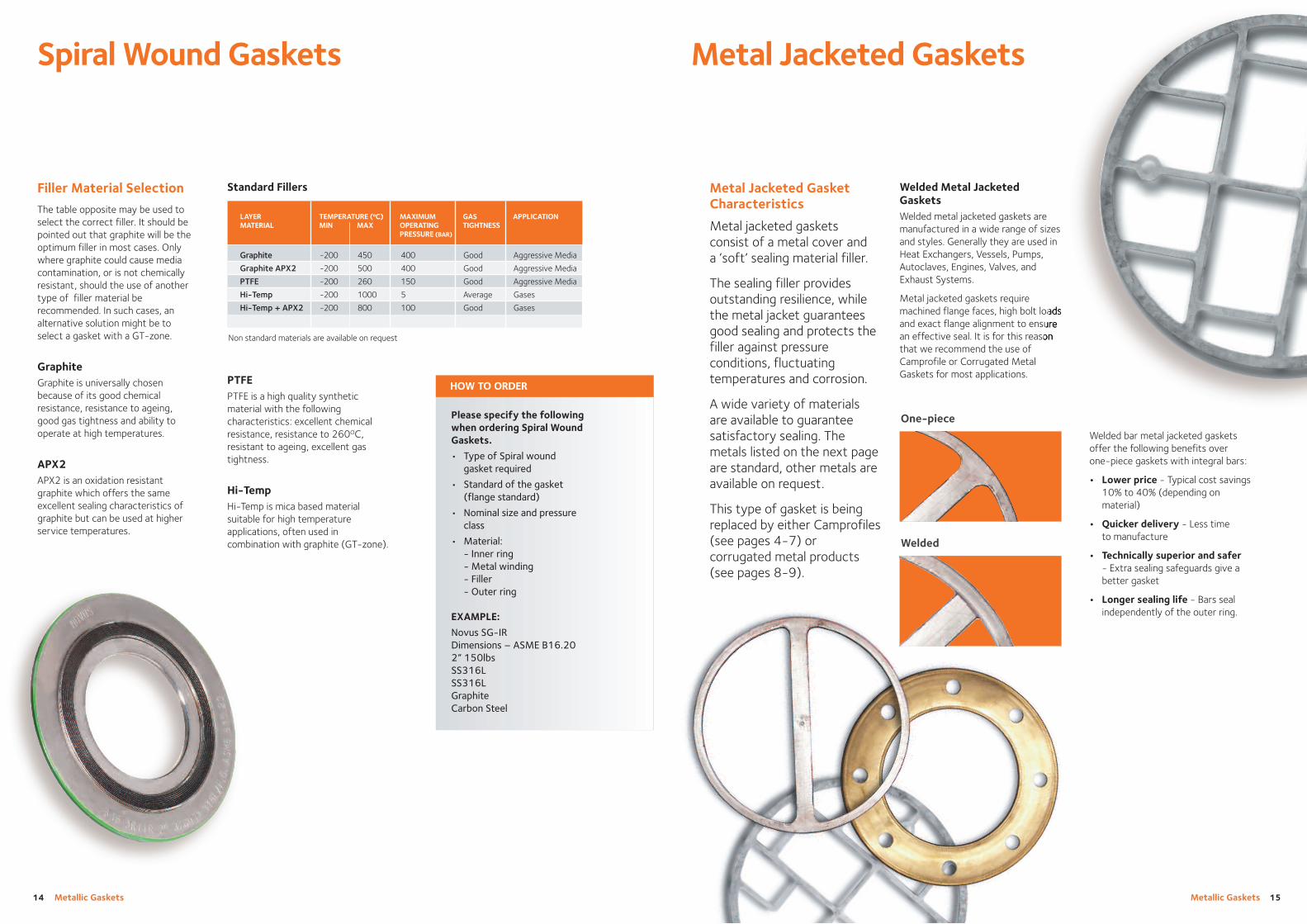
One-piece
Metal Jacketed GasketCharacteristics
Metal jacketed gasketsconsist of a metal cover and a ‘soft’ sealing material filler.
The sealing filler providesoutstanding resilience, whilethe metal jacket guaranteesgood sealing and protects thefiller against pressureconditions, fluctuatingtemperatures and corrosion.
A wide variety of materials are available to guaranteesatisfactory sealing. Themetals listed on the next pageare standard, other metals areavailable on request.
This type of gasket is beingreplaced by either Camprofiles(see pages 4-7) orcorrugated metal products(see pages 8-9).
Welded
Welded bar metal jacketed gasketsoffer the following benefits overone-piece gaskets with integral bars:
• Lower price - Typical cost savings10% to 40% (depending onmaterial)
• Quicker delivery - Less timeto manufacture
• Technically superior and safer- Extra sealing safeguards give abetter gasket
• Longer sealing life - Bars sealindependently of the outer ring.
Welded Metal JacketedGasketsWelded metal jacketed gaskets aremanufactured in a wide range of sizesand styles. Generally they are used in Heat Exchangers, Vessels, Pumps,Autoclaves, Engines, Valves, andExhaust Systems.
Metal jacketed gaskets requiremachined flange faces, high bolt loadsand exact flange alignment to ensurean effective seal. It is for this reasonthat we recommend the use ofCamprofile or Corrugated MetalGaskets for most applications.
Metallic Gaskets 17
Metal Jacketed Gaskets
16 Metallic Gaskets
Installation Guide
Type S6 Seating Stress
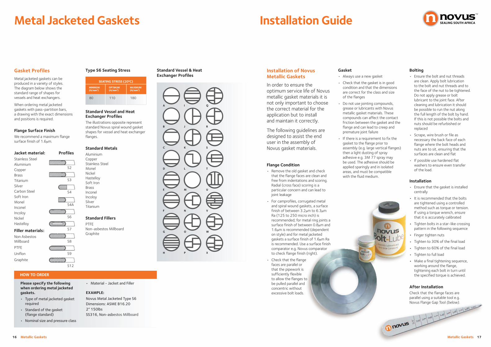
Standard Vessel and HeatExchanger ProfilesThe illustrations opposite representstandard Novus spiral wound gasketshapes for vessel and heat exchangerflanges.
Standard MetalsAluminiumCopperStainless SteelMonelNickelHastelloySoft IronBrassInconelIncoloySilverTitanium
Standard FillersPTFENon-asbestos MillboardGraphite
Gasket Profiles
Metal jacketed gaskets can beproduced in a variety of styles. The diagram below shows thestandard range of shapes forvessels and heat exchangers.
When ordering metal jacketedgaskets with pass-partition bars, a drawing with the exact dimensionsand positions is required.
Flange Surface FinishWe recommend a maximum flangesurface finish of 1.6μm.
Jacket material: ProfilesStainless SteelAluminiumCopperBrassTitaniumSilverCarbon SteelSoft IronMonelInconelIncoloyNickelHastelloy
Filler materials:Non Asbestos Millboard
PTFE
Uniflon
Graphite
S2
S3
S4
S4A
S6
S7
S8
S9
S12
80 110 180
SEATING STRESS (20oC)
MINIMUM(N/mm2)
OPTIMUM(N/mm2)
MAXIMUM(N/mm2)
A
B
C
D
E
F
G
H
Standard Vessel & HeatExchanger Profiles
I
J
K
L
M
N
O
P
Q
R
S
T
U
V
W
X
Please specify the followingwhen ordering metal jacketedgaskets.
• Type of metal jacketed gasketrequired
• Standard of the gasket(flange standard)
• Nominal size and pressure class
How to OrderHOW TO ORDER
• Material - Jacket and Filler
EXAMPLE:
Novus Metal Jacketed Type S6Dimensions: ASME B16.202” 150lbsSS316, Non-asbestos Millboard
Installation of Novus Metallic Gaskets
In order to ensure theoptimum service life of Novusmetallic gasket materials it isnot only important to choosethe correct material for theapplication but to install and maintain it correctly.
The following guidelines aredesigned to assist the enduser in the assembly ofNovus gasket materials.
Gasket• Always use a new gasket
• Check that the gasket is in goodcondition and that the dimensionsare correct for the class and sizeof the flanges
• Do not use jointing compounds,grease or lubricants with Novusmetallic gasket materials. Thesecompounds can affect the contactfriction between the gasket and theflange and can lead to creep andpremature joint failure
• If there is a requirement to fix thegasket to the flange prior toassembly (e.g. large vertical flanges)then a light dusting of sprayadhesive e.g. 3M 77 spray maybe used. The adhesive should beapplied sparingly and in isolatedareas, and must be compatiblewith the fluid medium.
Bolting• Ensure the bolt and nut threads
are clean. Apply bolt lubricationto the bolt and nut threads and tothe face of the nut to be tightened.Do not apply grease or boltlubricant to the joint face. Aftercleaning and lubrication it shouldbe possible to run the nut alongthe full length of the bolt by hand.If this is not possible the bolts andnuts should be refurbished orreplaced
• Scrape, wire brush or file asnecessary the back face of eachflange where the bolt heads andnuts are to sit, ensuring that thesurfaces are clean and flat
• If possible use hardened flatwashers to ensure even transferof the load.
Installation• Ensure that the gasket is installed
centrally
• It is recommended that the boltsare tightened using a controlledmethod such as torque or tension.If using a torque wrench, ensurethat it is accurately calibrated
• Tighten bolts in a star-like crossingpattern in the following sequence
• Finger tighten nuts
• Tighten to 30% of the final load
• Tighten to 60% of the final load
• Tighten to full load
• Make a final tightening sequence,working around the flange,tightening each bolt in turn untilthe specified torque is achieved.
After InstallationCheck that the flange faces areparallel using a suitable tool e.g. Novus Flange Gap Tool (below).
Flange Condition• Remove the old gasket and check
that the flange faces are clean andfree from indentations and scoring.Radial (cross face) scoring is aparticular concern and can lead tojoint leakage
• For camprofiles, corrugated metaland spiral wound gaskets, a surfacefinish of between 3.2μm to 6.3μmRa (125 to 250 micro inch) isrecommended; for metal ring joints asurface finish of between 0.8μm and1.6μm is recommended (dependenton style) and for metal jacketedgaskets a surface finish of 1.6μm Rais recommended. Use a surface finishcomparator e.g. Novus comparatorto check flange finish (right).
• Check that the flangefaces are parallel orthat the pipework issufficiently flexibleto allow the flanges tobe pulled parallel andconcentric withoutexcessive bolt loads.

Ring Type Joint ProfilesType R Ring Type Joints
Novus models M8 and M9
M8 model R oval section and M9model R octagonal section ring typejoints are designed for flanges withstandard ring type grooves. Thesestandard shapes are used to sealpressures up to 5,000 psi inaccordance with API 6A.
The octagonal cross section has ahigher sealing efficiency than the oval cross section and is thereforepreferred. The oval section ring jointswere originally designed for the nowobsolete round bottom groove. Boththe oval and the octagonal crosssection are interchangeable on the flat bottom groove design.
We suppy a range of specialisedRing Type Joints for critical andnon standard applications to suitthe requirements of thepetrochemical industry.
Cam-ORJThe Cam-ORJ is a standard API 6Aoctagonal ring joint but with the fourangled seating surfaces concentricallyserrated and faced with oxidationinhibited graphite. The gasket offersthe high sealing efficiency associatedwith the octagonal design but withthe added benefit of being capable ofsealing flanges with minor damage.Under compression the graphiteflows into minor imperfectionscreating a tight seal.
The Cam-ORJ is available in a rangeof Alloy materials and in sizing to suitASME B16.5 or API 6A flanges.
Novus model M8R and M9R
Rubber Coated Ring Type Joints
This is an octagonal/oval section ringtype joint generally soft iron or lowcarbon steel totally enclosed in anitrile rubber coating. Widely used inpressure testing procedures,minimising any damage to the flange.
M8
M9
Metallic Gaskets 19
Novus Ring Type Joints
18 Metallic Gaskets
Ring Type Joints
Ring type joints are designedto concentrate the bolt loadover a small area thusproducing high seatingstresses. As the ring typematerial should always besofter than the matingflanges, the high seatingstress causes ‘plastic-flow’ of the ring joint in the flangefaces creating the seal.
Type RX Ring Type Joints
Novus model M12/M12S
M12 model RX ring type joints aredesigned for pressures up to 5,000psi.
A pressure activated ring joint, itsshape is designed so that the fluidpressure increases sealability. The outside sealing surface of thering joint makes the initial contactwith the flange. As the internalpressure rises the contact pressurebetween ring joint and flange alsoincreases. This is sometimes referredto as a pressure activated ring joint.due to the shape of the gasket. High seating pressures are createdincreasing the sealability. This designcharacteristic makes the RX ring jointmore resistant to vibrations, pressuresurges and shocks that occur duringoil well drilling.
M12S Model SBX ring type joint isthe same in design to the RX ring,however, the suffix ‘S’ indicates thatadditional pressure equalisation holeshave been drilled in accordance withAPI 17D for use on sub sea wellheadand christmas tree equipment.
M12
Novus model M12PI
Ring Type Joints with PTFE Inserts
M12 model RX ring type joints can be supplied with PTFE inserts.Designed to reduce turbulent flowand eliminate ring joint and flangecorrosion. The insert is speciallydesigned with radially drilled holesensuring the self-energisingperformance is not affected. Theinsert is located between the insidediameter of the ring joint and thebore of the flange. On assembly, the insert is captured between theflanges, filling the void between ringjoint and flange bore.
Blind Ring Type JointsThese specialised ring type joints aredesigned and manufactured for thecustomer who has a requirement toblank off flanges and pipe work. Thejoints are standard rings but with amachined metallic centre.
Blind ring type joints can be suppliedin a variety of materials.
(Continued on page 20)
RX Ring Type Joint
PTFE InsertType BX Ring Type Joints
Novus model M11/M11S
M11 model BX ring type joints aredesigned for pressures up to 20,000psi, suitable only for use with APItype BX flanges and grooves.
The gasket has a square cross sectionwith bevelled corners. The averagediameter of the ring joint is slightlygreater than that of the flangegroove. This way, when the ring jointis seated, it stays pre-compressed bythe outside diameter, creating high seating stress.
The M11S Model SBX ring type jointis the same design as the BX ring,however the suffix ‘S’ indicates thatadditional pressure equalisation holeshave been drilled in accordance withAPI 17D for use on sub sea wellheadand christmas tree equipment.
M11

Metallic Gaskets 21
Novus Ring Type Joints
20 Metallic Gaskets
Seating StressTo achieve a reliable seal, the ringtype joint should be assembled withinthe seating stress parameters shownin the table above.
Flange Surface FinishThe ring type joint and the sealingface of the groove must be free ofindentations, score marks, tool andchatter marks.
The maximum flange surface finishfor M8, M9, model R, M12 model RX is 1.6μm RA (63RMS).
The maximum flange surface finishfor M11 model BX is 0.8μm RA(32RMS).
For other materials please contact our technical department
SEATING STRESS (20oC)
MATERIAL IDENTIFICATION MINIMUM OPTIMUM MAXIMUM(N/mm2) (N/mm2) (N/mm2)
Soft Iron D 235 350 525
Low Carbon Steel S 265 400 600
A182FS FS 400 600 900
SS304 S304 335 500 750
SS316 S316 335 500 750
SS321 S321 335 500 750
SS347 S347 335 500 750
Please specify the followingwhen ordering Novus ring type joints.
• Ring type joint model
• Ring number/size& pressure rating
• Material/identification
• Flange standard
EXAMPLE:
M8 R OvalR16/Class 1” 3/600lbsSoft Iron or DASME/ANSI B16.5
Note: This can be abbreviated to R16D Oval RTJ
HOW TO ORDER
Combination Ring Type JointsThis ring type joint consists of twodifferent sizes having the same pitchdiameter, used for sealing and flangejoint where the mating flanges have different ring groove dimensions orprofiles.
These ring type joints can beproduced with either octagonal oroval facings, however they are notmanufactured in accordance with API specification.
Lens RingsThis is a contact seal for use in highpressure piping systems and inpressure vessel heads. Lens ringshave a spherical surface that requiresspecial matching of the flanges.Effective sealing is obtained atrelatively low bolt loads.
These ring type joints aremanufactured in accordance with DIN 2696. For enquiries completedrawings must be supplied.
Delta RingsThis is a pressure actuated ring usedprimarily on pressure vessels andvalve bonnets at pressures in excessof 5000 psi. Internal pressure forcesthe delta ring material to expand.
As with the Lens rings, all enquiriesand orders should be sent withcomplete drawings.
Ring Type Joint Profiles Hardness of Ring TypeJoint MaterialsOn installation, the material of thering joint has to be softer than that of the flange to avoid damage.
This table provides comparative dataof ring type joint material hardnessvalues.
* Brinell hardness measured with 3000kg, and 10mm diameter hardened steel ball. Softer materialsi.e. copper & brass are measured with 500kgs and 10mm diameter hardened steel ball.
* Rockwell B hardness is measured with 100kg and 1.60mm diameter steel ball.
MATERIAL IDENTIFI DIN DIN B.S. AISA-ASTM MAXIMUM HARDNESS TEMPERATURE (oC) DENSITY(TRADE NAME) -CATION SPECIFICATION MATERIAL UNS BRINELL ROCKWELL B MIN MAX (GR/CM2)
NO. HB HRB
Seating Stress
Soft Iron D - - - - 90 56 -40 500 7.85
Low Carbon Steel S R st 37.2 - - - 120 68 -40 500 7.85
F5 FS 5 Cr 0.5 mo 1.7362 - A182FS 130 72 -40 650 7.83
SS304 S304 X5Cr Ni 18 1.4301 304S15/16/13 304 160 83 -250 550 7.83
SS304L S304L X2 Cr Ni 18.9 1.4306 304S11 304L 160 83 -250 550 7.90
SS309 S309 X15 Cr Ni Si 20.12 1.4828 304S24 309 160 83 -100 1000 7.90
SS316 S316 X5 Cr Ni Mo 18.10 1.4401 316S16 316 160 83 -100 550 7.90
SS316L S316L X2 Cr Ni Mo 18.10 1.4404 316S11/13 316L 160 83 -100 550 7.90
SS316Ti S316Ti X10 Cr Ni Mo Ti 18.10 1.4571 320S31 316Ti 160 83 -100 550 7.80
SS321 S321 X10 Cr Ni Ti 18.9 1.4541 321S12/49/87 321 160 83 -250 550 7.90
SS347 S347 X10 Cr Ni Nb 18.9 1.4550 347S31 347 160 83 -250 500 7.90
SS410 S410 X6 Cr 13 1.4000 410S21 410 170 86 -20 850 7.80
254SMO 6Mo X1Cr Ni Mo Cu N20.18.7 1.4547 - S31254 180 89 -100 500 8.00
Duplex 2205 X2 Cr Ni Mo N 22.5.3 14462 31853 S31803/32205 230 approx 99 -40 300 7.80
Super Duplex 2507 X2 Cr Ni Mo N 25.6.3 14410 - S32750 230 approx 99 -40 300 7.80
Aluminium AL 1050 A1 99.5 3.0255 1B A91050 30 - -250 300 2.71
Silver Ag - - - - 28 (HV) - -250 750 10.50
Copper Cu SF-Cu 2.0090 C106 C12200 80 approx - -250 400 8.90
Brass CuZn37 Cu Za 37 (M563) 20321 CZ108 C27200 60 approx - -100 350 8.50
Nickel 200 Ni 200 Ni 99.2 2.4066 3072-76 NA11 NO2200 110 62 -250 600 8.90
Monel 400 400 Ni Cu 30 Fe 2.4360 3072-76 NA13 NO4400 150 80 -125 600 8.80
Inconel 600 600 Ni Cu 15 Fe 2.4816 3072-76 NA14 NO6600 150 80 -100 950 8.40
Inconel 625 625 Ni Cr 22 Mo 9 Mb 2.4856 3072-76 NA21 NO6625 150 80 -50 450 8.44
Incoloy 800 800 X10 Ni Cr A1 Ti 3220 1.4876 3072-76 NA15 NO8800 150 80 -100 850 8.00
Incoloy 825 825 Ni Cr 21 Mo 2.4858 3072-76 NA16 NO8825 195 92 -100 450 8.14
Hastelloy B2 B2 Ni Mo 28 2.4617 - N10665 230 99 -200 450 9.20
Hastelloy C276 C276 Ni Mo 16 Cr 15 W 2.4819 - N10276 210 95 -200 450 8.90
Titanium Ti2 Ti 99 8 3.7025 TA2 R50400 215 approx 96 -250 350 4.50
Metallic Gaskets 23
Technical &testing services
Training forthe future
Our engineers are available 24/7 to assist you with:
• Product recommendations
• Joint design and calculations
• Installation guidance
• On-site support
• Innovative software solutions
• Failure analysis and solutions
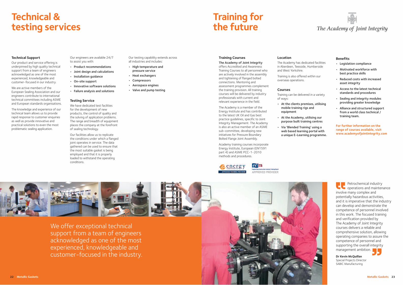
Testing ServiceWe have dedicated test facilities for the development of newproducts, the control of quality andthe solving of application problems.The range and breadth of equipmentplaces the company at the forefrontof sealing technology.
Our facilities allow us to replicate the conditions under which a flangedjoint operates in service. The datagathered can be used to ensure thatthe most suitable gasket is beingemployed and that it is properlyloaded to withstand the operatingconditions.
Technical SupportOur product and service offering isunderpinned by high quality technicalsupport from a team of engineersacknowledged as one of the mostexperienced, knowledgeable andcustomer-focused in our industry.
We are active members of theEuropean Sealing Association and ourengineers contribute to internationaltechnical committees including ASMEand European standards organisations.
The knowledge and experience of ourtechnical team allows us to providerapid response to customer enquiriesas well as provide innovative andpractical solutions to even the mostproblematic sealing application.
Benefits• Legislation compliance
• Motivated workforce withbest practice skills
• Reduced costs with increasedasset integrity
• Access to the latest technicalstandards and procedures
• Sealing and integrity modulesproviding greater knowledge
• Alliance and structured supportfrom a world class technical /training team.
For further information on therange of courses available, visitwww.academyofjointintegrity.com
LocationThe Academy has dedicated facilitiesin Aberdeen, Teesside, Humbersideand West Yorkshire.
Training is also offered within ouroverseas operations.
CoursesTraining can be delivered in a varietyof ways:
• At the clients premises, utilisingmobile training rigs andequipment
• At the Academy, utilising ourpurpose built training centres
• Via ‘Blended Training’ using aweb based learning portal witha unique E-Learning programme.
Training CoursesThe Academy of Joint Integrityoffers Accredited and AwarenessTraining Courses to all personnel whoare actively involved in the assemblyand tightening of flanged boltedconnections. Mentoring andassessment programmes complementthe training provision. All trainingcourses will be delivered by industryprofessionals with current andrelevant experience in the field.
The Academy is a member of theEnergy Institute and has contributedto the latest UK Oil and Gas bestpractice guidelines, specific to JointIntegrity Management. The Academyis also an active member of an ASMEsub-committee, developing newinitiatives for Pressure BoundaryBolted Flange Joint Assembly.
Academy training courses incorporateEnergy Institute, European (EN1591part 4) and ASME PCC-1-2010methods and procedures.
Petrochemical industry operations and maintenance
involve many complex andpotentially hazardous activities, and it is imperative that the industrycan develop and demonstrate thecompetence of personnel involved in this work. The focused trainingand verification provided by The Academy of Joint Integritycourses delivers a reliable andcomprehensive solution, allowingoperating companies to assure thecompetence of personnel andsupporting the overall integritymanagement ambition.
Dr Kevin McQuillan Special Projects Director SABIC Manufacturing
“
”22 Metallic Gaskets
We offer exceptional technicalsupport from a team of engineersacknowledged as one of the mostexperienced, knowledgeable andcustomer-focused in the industry.
Our testing capability extends acrossall industries and includes:
• High temperature andpressure service
• Heat exchangers
• Compressors
• Aerospace engines
• Valve and pump testing

UK OFFICEFlexitallic LtdScandinavia MillHunsworth LaneCleckheatonWest Yorkshire BD19 4LNEngland, UKT: + 44 (0)1274 851273F: + 44 (0)1274 300303E: [email protected]
Novus Sealing SA15 Coert Steynberg StreetVan Eck Park – Extension 2Brakpan, GautengSouth AfricaT: + 27 (0) 11 915 0016F: + 27 (0) 11 915 0940E: [email protected]
Novus Sealing Caspian LLP7v Atambayev StreetAtyrau, 060005, Republic of KazakhstanT: + 7(7122) 251103F: + 7(7122) 252835E: [email protected]
Novus Sealing Middle East LLCPO Box 6591, Al JazeeraWarehouse WIZ04-30 & 32Al Hamra Warehouse AreaRas Al KhaimahUnited Arab EmiratesT: + 971 (0)7 243 4305F: + 971 (0) 7 243 4306E: [email protected]
Novus Sealing (M) SDN BHDPlo 232Kawasan Perindustrian Tebrau III81100 Johor BahruJohor Darul TakzimMalaysiaT: + 607 351 3910F: + 607 357 9910E: [email protected]
Novus Sealing Nigeria LtdPlot 29A, Elelenwo StreetGRA Phase 1, Port HarcourtRivers State NigeriaT: + 234 (0) 84 901022E: [email protected]
NOVUS SEALING OVERSEAS OPERATIONS
Novus Sealing Pty Ltd15 Vinnicombe DriveCanning ValePerthWestern Australia 6155T: + 61 (08) 9455 2155F: + 61 (08) 9455 2165E: [email protected]
Novus Sealing Technology(Shanghai) Co. LtdBld 1, No. 1069, Xuanzhen (E) RoadNanhui Industrial ParkShanghaiP.R. ChinaT: + 86 (0) 21 6608 0973F: + 86 (0) 21 6608 0977E: [email protected]
www.novusproducts.eu Jan
20
13
- R
ev 2
www.novussealing.co.za [email protected]
Head Office
15 Coert Steynberg StreetVan Eck Park , Ext 2BrakpanGautengTel : +27 (0) 11 915 0016/25/30Fax : +27 (0) 11 915 0940Fax : 086 500 2788
Sasolburg Branch
28 Saturn RoadNaledi ParkSasolburgFree StateTel : +27 (0) 16 971 2945/63Fax : +27 (0) 16 971 2656
Secunda Branch
Unit 1C13 Danie Theron StreetSecundaMpumalangaTel : +27 (0) 17 631 5114Fax : +27 (0) 17 631 5205
Rustenburg Branch
Unit B595 Ridder StreetPlatinum Business CentreRustenburg Industrial AreaRustenburgNorth WestTel : +27 (0) 14 596 5565Fax : +27 (0) 14 596 5566
NOVUS SEALING SOUTH AFRICA