Metal Framing Product and Engineering...
116
December 2011 For the most current product/pricing information on Anvil products, please visit our website at www.anvilintl.com. Metal Framing Product and Engineering Catalog B U I L D I N G C O N N E C T I O N S T H A T L A S T
Transcript of Metal Framing Product and Engineering...

December 2011For the most current product/pricing information on Anvil products, please visit our website at www.anvilintl.com.
Metal Framing Product and Engineering Catalog
B U I L D I N G C O N N E C T I O N S T H A T L A S T

For over 150 years, Anvil has worked diligently to
build a strong, vibrant tradition of making connections —
pipe to pipe and people to people.
We pride ourselves in providing the finest-quality pipe products and
services with integrity and dedication to superior customer service at all levels.
We provide expertise and product solutions for a wide range of applications,
from plumbing, mechanical, HVAC, industrial and fire protection to mining,
oil and gas. Our comprehensive line of products includes: grooved pipe
couplings, grooved and plain-end fittings, valves, cast and malleable iron fittings,
forged steel fittings, steel pipe nipples and couplings, pipe hangers and supports,
channel and strut fittings, mining and oil field fittings, along with much more.
As an additional benefit to our customers, Anvil offers a complete and
comprehensive Design Services Analysis for mechanical equipment rooms, to
help you determine the most effective and cost-efficient piping solutions.
At Anvil, we believe that responsive and accessible customer support is
what makes the difference between simply delivering products —
and delivering solutions.
B U I L D I N G C O N N E C T I O N S T H AT L A S T

The Anvil-Strut™ product line includes metal framing channels, spring nuts, pipe
and conduit supports, and fittings and accessories. Strut is designed to provide
durable, dependable, and economical performance in clean rooms, satellite
dish supports, x-ray supports, storage racks, theater screen, tunnel stanchions
and offshore catwalk applications.
Anvil-Strut channels are manufactured by a series of forming dies (rolls) which
progressively cold work the strip steel into the desired channel configuration.
This method produces a cross-section of uniform dimensions with a tolerance
of +/- .015" on outside dimensions. These channels are produced from
prime structural steel and are ASTM approved. The channels are available
as pre-galvanized steel, plain steel, stainless steel, and aluminum. Channel
configurations of two or more elements are spotwelded, providing a wide
range of combination options. The spotwelds are spaced two or three inches
on centers throughout the length of the multiple channel sections.
Anvil-Strut channels are stocked in pre-galvanized and painted super-green.
Some sizes are stocked in stainless steel, zinc dichromate, PVC coated, or hot
dipped galvanized. Regular stocked lengths of Anvil-Strut channels are 10 and
20 foot, with tolerances of +/- 1/8". Other lengths are available upon request.
Anvil-Strut™
Anvil-Strut™ complete line of
continuous strut and strut fittings
with channels, fittings and
accessories can be used in a
variety of small or large, light or
heavy applications.
They include:
Metal Framing Product and Engineering Catalog
AS-12.11

PICTORIAL INDEX
www.anvilintl.com4
Section Description . . . . . . . . . . . . . . . . . . . . . . . . . . . . . . . Page
— Pictorial Index . . . . . . . . . . . . . . . . . . . . . . . . . . . . . . . . . 5–14
1 Channel . . . . . . . . . . . . . . . . . . . . . . . . . . . . . . . . . . . . . 15–36
2 Channel Nuts and Hardware . . . . . . . . . . . . . . . . . . . . 37–40
3 Fittings and Accessories . . . . . . . . . . . . . . . . . . . . . . . 41–61
4 Pipe and Conduit Supports . . . . . . . . . . . . . . . . . . . . . 62–68
5 Klo-Shure® . . . . . . . . . . . . . . . . . . . . . . . . . . . . . . . . . . . 69-71
6 Concrete Inserts . . . . . . . . . . . . . . . . . . . . . . . . . . . . . . 72–74
7 Specialty Strut . . . . . . . . . . . . . . . . . . . . . . . . . . . . . . . . 75–88
8 Technical Information . . . . . . . . . . . . . . . . . . . . . . . . 89–100
— Product Index . . . . . . . . . . . . . . . . . . . . . . . . . . . . . . 101–103
— Pipe Hanger Pictorial Index . . . . . . . . . . . . . . . . . . . 104-108
TO OUR VALUED CUSTOMERSAnvil-Strut™ products are carefully designed and manufactured to the listed standards, as applicable. However, Anvil-Strut™ reserves the right to revise product design without notification. Anvil-Strut™ products included in this catalog are intended for installation and service only as described or specified herein. Care should be exercised by installers and end-users to install, use and maintain these products properly to avoid any possible on-the-job accidents. Prices subject to change without notice.
AS-12.11

PICTORIAL INDEX
www.anvilintl.com 5
CHANNELS
AS 100Channel
Size: 15/8" x 31/4" x 12 GA.Pages 18 & 19
AS 100EHChannel with
Elongated HolesSize: 15/8" x 31/4" x 12 GA.
9/16" x 11/8" Elongated Holes on 2" Centers.
Page 19
AS 100KOChannel withKnock Outs
Size: 15/8" x 31/4" x 12 GA.7/8" Knock Outs on 6" Centers.
Page 19
AS 100HChannel with Holes
Size: 15/8" x 31/4" x 12 GA.9/16" Holes on 17/8" Centers.
Page 19
AS 100SChannel with Long SlotsSize: 15/8" x 31/4" x 12 GA.
13/32" x 3" Slots on 4" CentersPage 19
AS 100BTBWelded Channel
Size: 15/8" x 61/2" x 12 GA.Two Pcs. AS 100 Welded
Back-to-Back.Pages 18 & 19
AS 150Channel
Size: 15/8" x 27/16" x 12 GA.Pages 20 & 21
AS 150EHChannel with
Elongated HolesSize: 15/8" x 27/16" x 12 GA. 9/16" x 11/8" Elongated Holes
on 2" Centers.Page 21
AS 150KOChannel withKnock Outs
Size: 15/8" x 27/16" x 12 GA. 7/8" Knock Outs on 6" Centers.
Page 21
AS 150HChannel with Holes
Size: 15/8" x 27/16" x 12 GA. 9/16" Holes on 17/8" Centers.
Page 21
AS 150SChannel with Long SlotsSize: 15/8" x 27/16" x 12 GA.
13/32" x 3" Slots on 4" Centers.Page 21
AS 150BTBWelded Channel
Size: 15/8" x 47/8" x 12 GA.Two Pcs. AS 150 Welded
Back-to-Back.Pages 20 & 21
AS 200Channel
Size: 15/8" x 15/8" x 12 GA.Pages 22 & 23
AS 200EHChannel with
Elongated HolesSize: 15/8" x 15/8" x 12 GA.
9/16" x 11/8" Elongated Holes on 2" Centers.
Page 23
AS 200KOChannel withKnock Outs
Size: 15/8" x 15/8" x 12 GA. 7/8" Knock Outs on 6" Centers.
Page 23
AS 200HChannel with Holes
Size: 15/8" x 15/8" x 12 GA. 9/16" Holes on 17/8" Centers.
Page 23
AS 200SChannel with Long SlotsSize: 15/8" x 15/8" x 12 GA.
13/32" x 3" Slots on 4" Centers.Page 23
AS 200BTBWelded Channel
Size: 15/8" x 31/4" x 12 GA.Two Pcs. AS 200 Welded
Back-to-Back.Pages 22 & 24
AS 200STSWelded Channel
Size: 15/8" x 31/4" x 12 GA.Two Pcs. AS 200 Welded
Back-to-Back.Page 24
AS 200BTSWelded Channel
Size: 15/8" x 31/4" x 12 GA.Two Pcs. AS 200 Welded
Side-to-Back.Page 24
AS 200STSRWelded Channel
Size: 15/8" x 31/4" x 12 GA.Two Pcs. AS 200 Welded Side-to-Opposite Side.
Page 24
AS 200BTBSWelded Channel
AS 200BTBF3Welded Channel
AS 210Channel
Size: 15/8" x 15/8" x 14 GA.Pages 25 & 26
AS 210EHChannel with
Elongated HolesSize: 15/8" x 15/8" x 14 GA.
9/16" x 11/8" Elongated Holes on 2" Centers.
Page 26
AS 210KOChannel withKnock Outs
Size: 15/8" x 15/8" x 14 GA. 7/8" Knock Outs on 6" Centers.
Page 26
AS 210HChannel with Holes
Size: 15/8" x 15/8" x 14 GA. 9/16" Holes on 17/8" Centers.
Page 26
AS 210SChannel with Long SlotsSize: 15/8" x 15/8" x 14 GA.
13/32" x 3" Slots on 4" Centers.Page 26
AS 210BTBWelded Channel
Size: 15/8" x 31/4" x 14 GA.Two Pcs. AS 210 Welded
Back-to-Back.Pages 25 & 26
Discontinued
AS 200H3Channel with Holeson all Three Sides
Size: 15/8" x 15/8" x 12 GA. 9/16" Holes on all three sides
are on 17/8" Centers.Page 23
AS-12.11
AS 200EH BTBWelded Channel
Size: 15/8" x 31/4" x 12 GA.Two Pcs. AS 200EH Welded
Back-to-Back.9/16" x 11/8" Elongated Holes
on 2" Centers.Page 24

PICTORIAL INDEX
www.anvilintl.com6
AS 300Channel
Size: 15/8" x 13/8" x 12 GA.Pages 27 & 28
AS 300EHChannel with
Elongated HolesSize: 15/8" x 13/8" x 12 GA.
9/16" x 11/8" Elongated Holes on 2" Centers.
Page 28
AS 300KOChannel withKnock Outs
Size: 15/8" x 13/8" x 12 GA. 7/8" Knock Outs on 6" Centers.
Page 28
AS 300HChannel with Holes
Size: 15/8" x 13/8" x 12 GA. 9/16" Holes on 17/8" Centers.
Page 28
AS 300SChannel with Long SlotsSize: 15/8" x 13/8" x 12 GA.
13/32" x 3" Slots on 4" Centers.Page 28
AS 300BTBWelded Channel
Size: 15/8" x 23/4" x 12 GA.Two Pcs. AS 300 Welded
Back-to-Back.Pages 27 & 28
AS 400Channel
Size: 15/8" x 1" x 12 GA.Pages 29 & 30
AS 400EHChannel with
Elongated HolesSize: 15/8" x 1" x 12 GA.
9/16" x 11/8" Elongated Holes on 2" Centers.
Page 30
AS 400KOChannel withKnock Outs
Size: 15/8" x 1" x 12 GA.7/8" Knock Outs on 6" Centers.
Page 30
AS 400HChannel with Holes
Size: 15/8" x 1" x 12 GA.9/16" Holes on 17/8" Centers.
Page 30
AS 400SChannel with Long Slots
Size: 15/8" x 1" x 12 GA. 13/32" x 3" Slots on 4" Centers.
Page 30
AS 400BTBWelded Channel
Size: 15/8" x 2" x 12 GA.Two Pcs. AS 400 Welded
Back-to-Back.Pages 29 & 30
AS 500Channel
Size: 15/8" x 13/16" x 14 GA.Pages 31 & 32
AS 500EHChannel with
Elongated HolesSize: 15/8" x 13/16" x 14 GA.
9/16" x 11/8" Elongated Holes on 2" Centers.
Page 32
AS 500HChannel with Holes
Size: 15/8" x 13/16" x 14 GA. 9/16" Holes on 17/8" Centers.
Page 32
AS 500SChannel with Long SlotsSize: 15/8" x 13/16" x 14 GA.
13/32" x 3" Slots on 4" Centers.Page 32
AS 500BTBWelded Channel
Size: 15/8" x 15/8" x 14 GA.Two Pcs. AS 500 Welded
Back-to-Back.Pages 31 & 32
AS 520Channel
Size: 15/8" x 13/16" x 12 GA.Pages 33 & 34
AS 520EHChannel with
Elongated HolesSize: 15/8" x 13/16" x 12 GA.
9/16" x 11/8" Elongated Holes on 2" Centers.
Page 34
AS 520HChannel with Holes
Size: 15/8" x 13/16" x 12 GA. 9/16" Holes on 17/8" Centers.
Page 34
AS 520SChannel with Long SlotsSize: 15/8" x 13/16" x 12 GA.
13/32" x 3" Slots on 4" Centers.Page 34
AS 520BTBWelded Channel
Size: 15/8" x 15/8" x 12 GA.Two Pcs. AS 520 Welded
Back-to-Back.Pages 33 & 34
AS 560Channel
Size: 15/8" x 13/16" x 16 GA.Pages 35 & 36
AS 560EHChannel with
Elongated HolesSize: 15/8" x 13/16" x 16 GA.
9/16" x 11/8" Elongated Holes on 2" Centers.
Page 36
AS 707Metal RacewayClosure Strip
For All 15/8" Width Channels.(10' Length)
Page 36
AS 707PMetal PaintedClosure Strip
For All 15/8" Width Channels.(10' Length)
Page 36
AS LS - Clamping Nut with Long Spring
Use with AS 100 & AS 150Pages 37 & 38
AS NS - Clamping Nut without Spring
Use with all 15/8" wide channelPages 37 & 38
AS SS - Clamping Nut with Short Spring
Use with AS 400 and AS 500Pages 37 & 38
AS RS - Clamping Nut with Regular Spring
Use with AS 200, AS 210 and AS 300
Pages 37 & 38
AS TG - Top Grip Nut with Spring on Top
Use with all 15/8" wide channelPages 37 & 38
AS 517Stud Nut with RS Spring
Pages 37 & 38
CHANNELS (Continued)
CHANNEL NUTS
AS-12.11

PICTORIAL INDEX
www.anvilintl.com 7
CHANNEL HARDWARE
AS 3281Double Conveyer
Adjusting NutUse with all 15/8" wide channel
Page 39
AS 83Hexagon Nut
Page 39
Fig. 135Rod Coupling
Page 39
Fig. 146Continuous Threaded Rod
Page 39
AS 203Linked Eyelet with Stud
Page 39
AS 209Flat Washer
Page 39
AS 211Lock Washer
Page 40
AS 230Fender Washer
Page 40
AS 6075Slotted Hex HeadMachine Screw
Page 40
AS 6108Square Nut
Page 40AS 3500
Seismic Rod StiffenerPage 40
AS 6024Hex Head Cap Screw
Page 40
AS 85Rod or Insulator Support
Page 41
Fig. 86Clamp with Lock Nut
Page 41
Fig. 93Top Beam "C" ClampSize Range: 3/8" - 1/2"
Page 41
Fig. 94Top Beam "C" ClampSize Range: 5/8" - 3/4"
Page 41
Fig. 95Clamp with Lock Nut
Page 41
AS 135XLight Duty Beam Clamp
Page 41
AS 684Beam Clamp
Page 46
AS 685Beam Clamp
Page 46
AS 686Beam Clamp
Page 46
AS 855Angular "C" Beam ClampAS 855 1 - Use with AS 200
and AS 210.AS 855 2 - Use with AS 500.
Page 51
AS 858Heavy Duty Suspension
Rod Beam ClampSafety Anchor Strap AS 871
sold separately.Page 51
AS 865Wide Throat Heavy Duty
Beam ClampSafety Anchor Strap AS 871
sold separately.Page 51
AS 871Safety Anchor Strap
(For Heavy Duty Beam Clamps)Page 52
AS 907"I" Beam Clamp
Includes Cup Point Set Screw.Page 52
AS 998"I" Beam ClampIncludes Set Screw.
Page 54
AS 2623Swivel Adapter
Use with AS 2622 Beam Clamp.
Page 57
AS 2651Beam Clamp
Page 58
AS 2656"U" Bolt Beam Clamp
with HookPage 58
AS 2657Double "U" Bolt
Beam ClampPage 58
CLAMPS & ACCESSORIES
AS-12.11

PICTORIAL INDEX
www.anvilintl.com8
PLATES
AS 601Two Hole Splice Plate
Page 42
AS 602Three Hole Splice Plate
Page 42
AS 617Three Hole Swivel Plate
Page 43
AS 620Two Hole Connecting Plate
Page 43
AS 712Cross Plate
Page 47
AS 714"T" PlatePage 47
AS 715"T" Plate - 90˚
Page 47
AS 718Flat Angle Plate
Page 48
AS 719Four Hole Corner Plate
Page 48
AS 888Four Hole Splice Plate
Page 52
AS 619Square Washer
Page 43
AS 2504Square Washer with
Channel GuidePage 55
AS 631Two Hole Splice Clevis
Use with AS 200 & AS 210.Page 44
AS 644Two Hole Splice Clevis
Use with AS 500 & AS 520.Page 44
AS 629Three Hole Splice ClevisUse with AS 200 & AS 210.
Page 44
AS 645Three Hole Splice ClevisUse with AS 500 & AS 520.
Page 44
AS 616Four Hole Splice ClevisUse with AS 200 & AS 210.
Page 43
AS 646Four Hole Splice Clevis
Use with AS 500.Page 44
AS 613"U" Support
Use with AS 200, AS 210 and AS 500BTB.
Page 43
AS 679"U" Support
Use with AS 100, AS 200BTB and AS 210BTB.
Page 46
AS 710"U" Support
Use with AS 300.Page 47
AS 929"U" Support
Use with AS 500 & AS 520.Page 53
AS 978"U" Support
Use with AS 400.Page 54
AS 2119"U" Connector
Page 54
AS 2648"U" Support
Use with AS 150.Page 57
AS 687Slotted "U" Support
Use with AS 200 & AS 210.Page 47
AS 721"U" Support
Use with AS 100, AS 200BTB and AS 210BTB.
Page 48
AS 678Three Hole "U" Support
Use with AS 150BTB.Page 46
AS 733Six Hole "U" Support
Use with AS 200 & AS 210.Page 48
AS 735Eight Hole "U" Support
Use with AS 200BTB.Page 48
AS 609Two Hole Offset
"Z" SupportPage 42
AS 611"Z" Support
Use with AS 200, AS 210 and AS 500BTB.
Page 42
AS 612"Z" Support
Use with AS 400.Page 43
AS 711"Z" Support
Use with AS 300.Page 47
AS 928"Z" Support
Use with AS 500 & AS 520.
Page 53
AS 2601"Z" Support
Use with AS 150.Page 57
SPLICE CLEVIS
"U" SUPPORTS
"Z" SUPPORTS
AS 756"Z" Support
Use With AS 100, AS 200BTB and AS 210BTB.
Page 49
AS-12.11

PICTORIAL INDEX
www.anvilintl.com 9
ANGLE FITTINGS & CONNECTORS
AS 603Two Hole End Angle
Page 42
AS 604Two Hole Corner Angle
Page 42
AS 624Two Hole Closed Angle
ConnectorPage 44
AS 633Two Hole Open Angle
ConnectorPage 44
AS 763, AS 764Slotted Adjustment
Corner AnglePage 49
AS 806Two Hole Angle with
Impressions on Both LegsPage 50
AS 921One Hole Angle
Page 52
AS 2144Corner Angle
Page 54
AS 2520Two Hole Adjustment Angle
Page 56
AS 2545Slotted 90˚ Angle
Page 57
AS 605Three Hole Corner Angle
Page 42
AS 606Three Hole Corner Angle
Page 42
AS 745Three Hole Corner Angle
Page 49
AS 3049Two Hole Slotted 90˚
Corner ConnectorPage 60
AS 607Four Hole Corner Angle
Page 42
AS 781Four Hole Open Angle
ConnectorPage 49
AS 793Four Hole Closed Angle
ConnectorPage 50
AS 614Four Hole Joint Corner
ConnectorPage 43
AS 615Four Hole Shelf Joint
Angle ConnectorPage 43
AS 689Adjustable Double
Slotted Corner ConnectorPage 47
AS 748Four Hole Corner Joint
ConnectorPage 49
AS 927Five Hole Corner Connector
Page 53
AS 744Flat Corner Connector
Page 48
AS 750Four Hole Corner Connector
Page 49
AS 2190Flat Corner Connector
Page 55
AS 747Symmetrical Four Hole
ConnectorPage 49
AS 854Flat Connector
Page 50
AS 925Symmetrical Three Hole
Joint ConnectorPage 53
AS 2112Cross Connector
Page 54
AS 665Four Hole Double Corner
ConnectorPage 45
AS 720RH & LH Angle Plate
ConnectorPage 48
AS 922 RH & LHTwo Hole Single Corner
Angle ConnectorPage 53
AS 923Five Hole Two Angle
ConnectorPage 53
AS 2128 RH & LHSix Hole Corner Connector
Page 54
AS 666Six Hole Double Corner
ConnectorPage 45
AS 821Eight Hole Double Angle
ConnectorPage 50
AS-12.11

PICTORIAL INDEX
www.anvilintl.com10
ANGLE FITTINGS & CONNECTORS (Continued)
AS 667Eight Hole Double Corner Connector
Page 45
AS 913Ten Hole Two Angle
Clevis ConnectorPage 52
AS 668Six Hole Three
Angle ConnectorPage 46
AS 669Twelve Hole Three Angle
Clevis ConnectorPage 46
AS 2560 & AS 2561Conduit Connector Fitting
AssemblyPage 57
AS 3060Offset Connector
Page 60
AS 9402Two Hole
Hinge ConnectorPage 61
AS 9403Three Hole
Hinge ConnectorPage 61
AS 9404Four Hole
Hinge ConnectorPage 61
AS 677Cup Support for
Standard Single StrutUse with AS 200 and AS 210.
Page 46
AS 993Inside Clevis
Page 54
AS 2401 thru AS 2403Ladder Rung
Page 55
AS 651Reversible Strut Bracket
Page 45
AS 661 T1Strut Bracket
(Slot Up)Page 45
AS 661 T2Strut Bracket(Slot Down)
Page 45
AS 708Single ChannelBracket Support
Use with AS 200, AS 210 and AS 500BTB.
Page 47
AS 732Shelf Bracket
Page 48
AS 809Double Channel Bracket
Page 50
AS 825 RH/LHPipe Axle Support
Page 50
AS 838 RH/LH6" thru 30" Shelf Bracket
Page 51
AS 926Strut Brace
Page 53
AS 2404 thru AS 2408Wall Ladder Bracket
Page 55
AS 242145˚ Stair Tread Support
Page 55
AS 2422341/2˚ Stair Tread Support
Page 55
AS 3164Double ChannelBracket Support
Use with all 31/4" Channels.Page 60
AS 3373Universal Angle Bracket
Page 60
AS 2627Spacer Clevis
Page 57
AS 2654 & AS 2654AColumn Attachment
Page 58
BRACKETS
AS-12.11

PICTORIAL INDEX
www.anvilintl.com 11
POST BASES
AS 2064Double Column
Post BaseUse with AS 100, AS 200BTB, AS 200STS, AS 200BTS and
AS 200STR ChannelPage 54
AS 3013Single Column
Post BaseUse with AS 200 and
AS 210 Channel.Page 58
AS 3025Post Base
Use with AS 200 andAS 210 Channel.
Page 59
AS 3029Double Column
Post BaseUse with all 31/4" Channels.
Page 59
AS 3033Post Base
Use with AS 200 andAS 210 Channel.
Page 59
AS 3040Post Base
Use with AS 200 andAS 210 Channel.
Page 59
AS 3064Double Column Post BaseUse with all 31/4" Channels.
Page 59
AS 9400Adjustable Base
Page 61
AS 2521Two Wheel Trolley
Use with As 200 Channel.Page 56
AS 2522Four Wheel Trolley
Use with AS 200 Channel.Page 56
AS 2524Two Wheel
Light Duty Trolley
AS 2525Four Wheel
Light Duty Trolley
AS 2528Trolley Beam Standard
SupportUse with AS 200 and
AS 210 Channel.Page 56
AS 2528-1Trolley Beam Joint
SupportUse with AS 200 and
AS 210 Channel.Page 56
AS 51Right Angle Pipe or
Conduit ClampPage 62
Fig. 67Pipe or Conduit Hanger
Page 62
Fig. 69Swivel Ring Hanger
Page 62
Fig. 137"U" Bolt with Nuts
Long TangentPage 62
AS 270Conduit Clamp
Page 62
AS 1450One Hole Clamp for
O.D. TubingPage 65
AS 3101 thru AS 3115One Piece Cable and
Conduit ClampPage 66
AS 3126Hold Down Clamp
Page 67
AS 1000EMT Conduit Clamps
offered in pre-assembled only.Page 63
AS 1100Rigid Steel Conduit Clampsoffered in pre-assembled only.
Page 63
AS 1200O.D. Tubing Clamp
offered in pre-assembled only.Page 64
AS 1300Universal Pipe Clamp
offered in pre-assembled only.Page 65
TROLLEYS & ACCESSORIES
PIPE & CONDUIT SUPPORTS
AS 3064 SQDouble Column Post BaseUse with all 31/4" Channels.
Page 60
DiscontinuedDiscontinued
AS 3013 SQSingle Column
Post BaseUse with AS 200 and
AS 210 Channel.Page 58
AS 3013 FLSingle Column
Post BaseUse with AS 200 and
AS 210 Channel.Page 58
AS 3025 FLPost Base
Use with AS 200 andAS 210 Channel.
Page 59
AS-12.11

PICTORIAL INDEX
www.anvilintl.com12
PIPE & CONDUIT SUPPORTS (Continued)
AS 815(6" to 18" Pipe) Double
Roller Pipe SupportPage 62
AS 1901(1" to 8" Pipe)
Pipe Roller SupportPage 65
AS 1902(1" to 8" Pipe)
Pipe Roller SupportPage 66
AS 1911(2" to 14" Pipe)
Pipe Roller SupportPage 66
AS 2631Swing Gate Fixture HangerUse with AS 200, AS 210,
AS 300, AS 400 andAS 500 Channels.
Page 57
AS 2631DSwing Gate Fixture HangerUse with AS 100, AS 150,
AS 200BTB and AS 210BTB Channels.Page 57
AS 3138Parallel Pipe Clamp
Page 67
AS 3792Cushion Strip
Page 67
AS 0040D thru AS 106PCushion Clamp Assembly
Page 68
Klo-Shure®
Strut-Mounted Insulation Couplings
with Strut ClampPage 69
Fig. 152Screw Concrete Insert
Page 72
Fig. 284Concrete Deck Insert
Fig. 285Light Weight
Concrete InsertPage 72
AS 349Continuous
Concrete Insertwith or without Closure Strip
and End Cap Installed.Page 72
AS 449Continuous
Concrete Insertwith or without Closure Strip
and End Cap Installed.Page 73
AS 6151Plastic Closure Strip
Page 74
AS 653Type "B" End Cap Anchor
Use with AS 349 Insert.Page 73
AS 654Type "B" End Cap Anchor
Use with AS 449 Insert.Page 73
AS 655 & AS 656Type "A" End Cap
Use with AS 200 Channel. Use with AS 300 Channel
and AS 349 Insert.Page 45
AS 901 & AS 902Type "A" End Cap
Use with AS 100 andAS 400 Channel.
Page 52
AS 930Type "A" End Cap
Use with AS 500 Channel.Page 53
AS 2511End Cap with Knockout
AS 2511 1 – Use with AS 100.AS 2511 2 – Use with AS 200
and AS 210.AS 2511 3 – Use with AS 300.
Page 56
AS 2580Type "A" End Cap
Use with AS 150 Channel.Page 57
AS 6153Safety End Cap
AS 6153 1 – Use with AS 100.AS 6153 2 – Use with AS 200
and AS 210.AS 6153 3 – Use with AS 300.AS 6153 5 – Use with AS 500.
Page 60
CONCRETE INSERTS
END CAPS
Discontinued
Klo-Shure®
Strut-Mounted Insulation Couplings with Non Metallic Strut Clamp
Page 70
Klo-Shure®
Strut-Mounted Insulation Couplings for
Fiberglass InsulationPage 71
AS-12.11

PICTORIAL INDEX
www.anvilintl.com 13
SPECIALTY STRUT (
AS 200 SS/ZTC/HGChannel
Size: 15/8" x 15/8" x 12 GA.Pages 76 & 77
AS 200EH SS/ZTC/HGChannel with Elongated Holes
Size: 15/8" x 15/8" x 12 GA. 9/16" x 11/8" Elongated Holes on 2" Centers.
Page 77
AS 200BTB SS/ZTC/HGWelded Channel
Size: 15/8" x 31/4" x 12 GA.Two Pcs. AS 200 Welded Back-to-Back.
Pages 76 & 77
AS 200EH BTB SS/ZTC/HGWelded Channel
Size: 15/8" x 31/4" x 12 GA.Two Pcs. AS 200EH Welded Back-to-Back.9/16" x 11/8" Elongated Holes on 2" Centers
Page 77
AS 210 SS/ZTC/HGChannel
Size: 15/8" x 15/8" x 14 GA.Pages 78 & 79
AS 210EH SS/ZTC/HGChannel with Elongated Holes
Size: 15/8" x 15/8" x 14 GA. 9/16" x 11/8" Elongated Holes on 2" Centers.
Page 79
AS 210BTB SS/ZTC/HGWelded Channel
Size: 15/8" x 31/4" x 14 GA.Two Pcs. AS 200 Welded Back-to-Back.
Pages 78 & 79
AS 500 SS/ZTC/HGChannel
Size: 15/8" x 13/16" x 14 GA.Pages 80 & 81
AS 500EH SS/ZTC/HGChannel with Elongated Holes
Size: 15/8" x 13/16" x 14 GA. 9/16" x 11/8" Elongated Holes on 2" Centers.
Page 81
AS 500BTB SS/ZTC/HGWelded Channel
Size: 15/8" x 15/8" x 14 GA.Two Pcs. AS 500 Welded Back-to-Back.
Pages 80 & 81
AS NS SS/ZTC Clamping Nutwithout Spring
Use with all 15/8" wide channelPage 82
AS RS SS/ZTCClamping Nut
with Regular SpringUse with AS 200, AS 210
and AS 300Page 82
AS 3500 ZTCSeismic Rod Stiffener
Page 88
AS 601 ZTCTwo Hole Splice Plate
Page 82
AS 602 ZTCThree Hole Splice Plate
Page 82
AS 619 SS/ZTCSquare Washer
Page 83
AS 712 ZTCCross Plate
Page 84
AS 714 ZTC"T" PlatePage 84
AS 718 ZTCFlat Angle Plate
Page 85
AS 888 ZTCFour Hole Splice Plate
Page 85
AS 616 ZTCFour Hole Splice ClevisUse with AS 200 & AS 210.
Page 83
AS 613 ZTC"U" Support
Use with AS 200, AS 210 and AS 500BTB.
Page 83
AS-12.11

PICTORIAL INDEX
www.anvilintl.com14
SPECIALTY STRUT ( Continued
AS 679 ZTC"U" Support
Use with AS 100, AS 200BTB and AS 210BTB.
Page 84
AS 929 ZTC"U" Support
Use with AS 500 & AS 520.Page 86
AS 611 ZTC"Z" Support
Use with AS 200, AS 210 and AS 500BTB.
Page 83
AS 928 ZTC"Z" Support
Use with AS 500 & AS 520.Page 86
AS 603 ZTCTwo Hole End Angle
Page 82
AS 604 ZTCTwo Hole Corner Angle
Page 82
AS 624 ZTCTwo Hole Closed Angle
ConnectorPage 83
AS 633 ZTCTwo Hole Open Angle
ConnectorPage 83
AS 605 ZTCThree Hole Corner Angle
Page 82
AS 606 ZTCThree Hole Corner Angle
Page 82
AS 607 ZTCFour Hole Corner Angle
Page 83
AS 720 ZTCRH & LH Angle Plate
ConnectorPage 85
AS 665 ZTCFour Hole Double Corner
ConnectorPage 84
AS 922 RH & LH ZTCTwo Hole Single Corner
Angle ConnectorPage 86
AS 923 ZTCFive Hole Two Angle
ConnectorPage 86
AS 666 ZTCSix Hole Double Corner
ConnectorPage 84
AS 821 ZTCEight Hole Double Angle
ConnectorPage 85
AS 667 ZTCEight Hole Double Corner Connector
Page 84
AS 913 ZTCTen Hole Two Angle
Clevis ConnectorPage 85
AS 668 ZTCSix Hole Three
Angle ConnectorPage 84
AS 669 ZTCTwelve Hole Three Angle
Clevis ConnectorPage 84
AS 651 ZTCReversible Strut Bracket
Page 83
AS 809 ZTCDouble Channel Bracket
Page 85
AS 3373 ZTCUniversal Angle Bracket
Page 88
AS 3033 ZTCPost Base
Use with AS 200 andAS 210 Channel.
Page 87
AS 3064 ZTCDouble Column Post BaseUse with all 31/4" Channels.
Page 87
AS 2651 ZTCBeam Clamp
Page 87
AS 1100 SS/ZTCRigid Steel Conduit Clampsoffered in pre-assembled only.
Page 86
AS 1200 SS/ZTCO.D. Tubing Clamp
offered in pre-assembled only.Page 87
AS-12.11

CHANNEL
Ch
ann
elN
uts
& H
ardw
are
Fitt
ings
Pipe
/Con
duit
Su
ppor
tsK
lo-S
hu
reC
oncr
ete
Inse
rts
Spec
ialt
y St
rut
Tech
nic
al D
ata
www.anvilintl.com 15
ANVIL-STRUT™ STYLES
ANVIL-STRUT™ CHANNEL FABRICATION DATA
S CHANNEL
Catalog # Gauge Dimensions Wt/100 Ft.
AS 100S 12 31/4 x 15/8 298#
AS 150S 12 27/16 x 15/8 239#
AS 200S 12 15/8 x 15/8 179#
AS 210S 14 15/8 x 15/8 130#
AS 300S 12 13/8 x 15/8 161#
AS 400S 12 1 x 15/8 134#
AS 520S 12 13/16 x 15/8 125#
AS 500S 14 13/16 x 15/8 94#
H 9/16 CHANNEL
Catalog # Gauge Dimensions Wt/100 Ft.
AS 100H 12 31/4 x 15/8 308#
AS 150H 12 27/16 x 15/8 249#
AS 200H 12 15/8 x 15/8 189#
AS 210H 14 15/8 x 15/8 140#
AS 300H 12 13/8 x 15/8 171#
AS 400H 12 1 x 15/8 144#
AS 520H 12 13/16 x 15/8 130#
AS 500H 14 13/16 x 15/8 98#
KO CHANNEL
Catalog # Gauge Dimensions Wt/100 Ft.
AS 100KO 12 31/4 x 15/8 313#
AS 150KO 12 27/16 x 15/8 254#
AS 200KO 12 15/8 x 15/8 194#
AS 210KO 14 15/8 x 15/8 145#
AS 300KO 12 13/8 x 15/8 176#
AS 400KO 12 1 x 15/8 149#
AS 520KO 12 13/16 x 15/8 135#
AS 500KO 14 13/16 x 15/8 103#
EH CHANNEL
Catalog # Gauge Dimensions Wt/100 Ft.
AS 100EH 12 31/4 x 15/8 308#
AS 150EH 12 27/16 x 15/8 254#
AS 200EH 12 15/8 x 15/8 189#
AS 210EH 14 15/8 x 15/8 140#
AS 300EH 12 13/8 x 15/8 171#
AS 400EH 12 1 x 15/8 144#
AS 520EH 12 13/16 x 15/8 130#
AS 500EH 14 13/16 x 15/8 98#
13/32" x 3" Slot, 4" on centers
9/16" x 11/8" Slot, 2" on centers
9/16" or 3/4" Dia. Hole, 17/8" on centers
7/8" Dia. Knockout, 6" on centers
S
EH
H
KO
SOLID
AS-12.11

CHANNEL
www.anvilintl.com16
WELDED COMBINATIONS
All welded combinations illustrated below are available in any of our Anvil-Strut™ channels, in any of the following material or finishes: Plain, Pre-Galvanized, Supr-Green or Stainless Steel.
Our welded channels are normally spotwelded with a maximum of 2 inches on center for EH. All other channels are 3 inches on center or MIG welded where spotwelding is not possible. Dimensions shown are for welded variations of the AS 200 channel.
NOTE: SLOTTED CHANNELS AVAILABLE IN ALL WELDED COMBINATIONS.
BTB STS BTS STSR
15/8"
31/4"
15/8"
31/4"
15/8"
31/4"
15/8"
31/4"
FTS
15/8"
31/4"
STS3 BTB4 BTB3
15/8"
47/8"
31/4"
31/4"
31/4"
31/4"
BTBF3
15/8"
47/8"
BTSB3
15/8"
47/8"
BTS3
31/4"
31/4"
BTBS
31/4"
31/4"
31/4""Discontinued
31/4""Discontinued
/4
Discontinued
31/4"Discontinued47/8"Discontinued
AS-12.11

CHANNEL
Ch
ann
elN
uts
& H
ardw
are
Fitt
ings
Pipe
/Con
duit
Su
ppor
tsK
lo-S
hu
reC
oncr
ete
Inse
rts
Spec
ialt
y St
rut
Tech
nic
al D
ata
www.anvilintl.com 17
CHANNEL SPECIFICATIONSGENERALAnvil-Strut™ channels are manufactured by a series of forming dies, or rolls, which progressively cold work the strip steel into the desired channel configuration. This method produces a cross section of uniform dimensions within a tolerance of plus or minus .015”, on outside dimensions.
MATERIALAnvil-Strut™ channels are produced from prime structural steel covered by the following specifications.
PRE-GALVANIZED STEEL . . . . . . . . . . . . . . . . . . . . . . . . . . . . ASTM A-653 PLAIN STEEL . . . . . . . . . . . . . . . . . . . . . . . . . . . . . . . . . . . . . . . ASTM A-1011-04 SS ALUMINUM (Type 6063T6) . . . . . . . . . . . . . . . . . . . . . . . . . ASTM B-221 STAINLESS STEEL (Type 304 and 316) . . . . . . . . . . . . . . . . . ASTM A-240 (See technical section for additional information.)
Other materials and specifications available on request. Certification (C of C or CMTR’s) if required must be requested at the time of ordering.
WELDINGChannel combinations of two or more elements are spotwelded together to form various multiple combinations. The spotwelds are spaced two or three inches on centers throughout the length of the multiple channel sections.
LENGTH INFORMATIONAnvil-Strut™ Channels are produced and stocked in 10 and 20 foot lengths with a tolerance of ± 1⁄8." Other lengths are available upon request.
FINISHESAll Anvil-Strut™ channels are stocked in pre-galvanized and powder coated Supr-Green. Some sizes are stocked in stainless steel, zinc trivalent chromium, PVC coated or hot dipped galvanized. (See technical section for additional information.)
LOADING DATA1. When calculating load at center of span, multiply uniform load from table by .5 and deflection by .8.2. When calculating beam and column loads for aluminum, multiply by .33.
BEAM AND COLUMN LOADING DATA* Not recommended - Kl/r exceeds 200.** For these loads, the uniform beam capacity is lower than the l/240 or l/360 beam capacity and is thereore the governing constraint.*** Load limited by spotweld shear.
NOTES1. The beam capacities shown above include the weight of the strut beam. The beam weight must be subtracted from these
capacities to arrive at the net beam capacity.2. Allowable beam loads are based on a uniformly loaded, simply supported beam.3. The load chart shows beam capacities for strut without holes. For strut with holes, multiply by the following: KO by .82, H 3/4 by .85,
H 9/16 by .88, EH by .88, S by .90.
AS-12.11

CHANNELLEGEND:GR: Powder Coated Supr-Green EG: Electro-Galvanized PG: Pre-Galvanized AL: Aluminum HG: Hot Dipped Galvanized PL: Plain SS: Stainless Steel ZTC: Zinc Trivalent Chromium For Stainless Steel (SS), Zinc Trivalent Chromium (ZTC) and Hot Dipped Galvanized (HG), refer to pages 76-81 in the Specialty Strut Section.
www.anvilintl.com18
AS 100 BEAM AND COLUMN LOADS
Span or Column
Anvil-Strut™ Catalog #
Max Load of Column Loaded
@ C.G.
Static Beam Load (X-X Axis)
Allowable Uniform Load @ 25,000 PSI (1758 Kg/cm2)
Deflection @ 25,000 PSI (1758 Kg/cm2)
Uniform Load @ l/240
Uniform Load @ l/360
In mm Lbs kg Lbs kg In mm Lbs kg Lbs kg
12 305 AS 100 12,428 5,637 10,155 4,606 0.007 0.178 ** ** ** **AS 100 BTB 26,291 11,925 5,130 *** 2,327 0.004 0.102 ** ** ** **
18 457 AS 100 11,161 5,063 6,770 3,071 0.016 0.406 ** ** ** **AS 100 BTB 25,442 11,540 5,130 *** 2,327 0.009 0.229 ** ** ** **
24 610 AS 100 9,531 4,323 5,077 2,303 0.029 0.737 ** ** ** **AS 100 BTB 24,359 11,049 5,130 *** 2,327 0.016 0.406 ** ** ** **
30 762 AS 100 7,642 3,466 4,062 1,842 0.045 1.143 ** ** ** **AS 100 BTB 23,122 10,488 5,130 *** 2,327 0.025 0.635 ** ** ** **
36 914 AS 100 5,767 2,616 3,385 1,535 0.065 1.651 ** ** ** **AS 100 BTB 21,805 9,891 5,130 *** 2,327 0.036 0.914 ** ** ** **
42 1,067 AS 100 4,550 2,064 2,901 1,316 0.088 2.235 ** ** ** **AS 100 BTB 20,472 9,286 5,130 *** 2,327 0.049 1.245 ** ** ** **
48 1,219 AS 100 3,754 1,703 2,539 1,152 0.115 2.921 ** ** ** **AS 100 BTB 19,169 8,695 5,130 *** 2,327 0.064 1.626 ** ** ** **
60 1,524 AS 100 2,803 1,271 2,031 921 0.180 4.572 ** ** 1,876 851AS 100 BTB 16,771 7,607 5,130 *** 2,327 0.099 2.515 ** ** ** **
72 1,829 AS 100 2,268 1,029 1,692 767 0.260 6.604 ** ** 1,303 591AS 100 BTB 14,733 6,688 5,130 *** 2,327 0.143 3.632 ** ** ** **
84 2,134 AS 100 1,927 874 1,451 658 0.354 8.992 1,436 651 957 434AS 100 BTB 13,073 5,930 4,515 2,048 0.195 4.953 ** ** ** **
96 2,438 AS 100 1,688 766 1,269 576 0.462 11.735 1,099 498 733 332AS 100 BTB 11,917 5,405 3,950 1,792 0.254 6.452 ** ** ** **
108 2,743 AS 100 1,509 684 1,128 512 0.585 14.859 869 394 579 263AS 100 BTB 9,933 4,506 3,512 1,593 0.322 8.179 ** ** 3,272 1,484
120 3,048 AS 100 1,366 620 1,015 460 0.722 18.339 703 319 469 213AS 100 BTB 8,046 3,650 3,160 1,433 0.398 10.109 ** ** 2,650 1,202
180 4,572 AS 100 * * 677 307 1.624 41.250 313 142 208 94AS 100 BTB * * 2,107 956 0.894 22.708 1,767 801 1,178 534
240 6,096 AS 100 * * 508 230 2.887 73.330 176 80 117 53AS 100 BTB * * 1,580 717 1.590 40.386 994 451 662 300
For Beam and Column Loading Data and load reduction information for channel with holes and concentrated loads, see notes on page 17.
PROPERTIES OF SECTION I = Moment of Inertia S = Section Modulus r = Radius of Gyration
Wt./Ft. Area of Section X-X Axis Y-Y Axis
Lbs kg Sq. In. Sq. Cm. I in4 I cm4 S in3 S cm3 r in. r cm. I in4 I cm4 S in3 S cm3 r in. r cm.AS 100 3.13 1.42 0.844 5.455 1.073 44.662 0.609 9.980 1.102 2.799 0.429 17.856 0.529 8.669 0.697 1.770AS 100BTB 6.26 2.84 1.768 11.406 6.064 252.403 1.896 31.070 1.852 4.704 0.859 35.754 1.057 17.321 0.697 1.770
AS 10031/4" x 15/8"12 Gauge Channel — wt./100 ft. - 313#
Stocked in pre-galvanized, plain and powder coated supr-green, in both 10 and 20 ft. lengths. Other materials, finishes and lengths are available upon request.
See page 16 for welded combinations.
31/4"(82.55)
15/8"(41.28)
7/8"(22.23)
3/8"(9.53)
9/32"(7.14)
X
Y
1.762"(44.75)
(mm) millimeters
AS-12.11

CHANNEL
Ch
ann
elN
uts
& H
ardw
are
Fitt
ings
Pipe
/Con
duit
Su
ppor
tsK
lo-S
hu
reC
oncr
ete
Inse
rts
Spec
ialt
y St
rut
Tech
nic
al D
ata
LEGEND:GR: Powder Coated Supr-Green EG: Electro-Galvanized PG: Pre-Galvanized AL: Aluminum HG: Hot Dipped Galvanized PL: Plain SS: Stainless Steel ZTC: Zinc Trivalent Chromium For Stainless Steel (SS), Zinc Trivalent Chromium (ZTC) and Hot Dipped Galvanized (HG), refer to pages 76-81 in the Specialty Strut Section.
www.anvilintl.com 19
AS 100 PL, GR, PG
SOLID
Wt/100 Ft: 305 lbs.
AS 100EH PL, GR, PG
WITH ELONGATED HOLES
Wt/100 Ft: 300 lbs.
AS 100S PL, GR, PG
WITH LONG SLOTS
Wt/100 Ft: 300 lbs.
AS 100KO PL, GR, PG
WITH KNOCK OUT
Wt/100 Ft: 305 lbs.
AS 100H PL, GR, PG
WITH HOLES
3/4" dia. holes available AS 100H MODWt/100 Ft: 300 lbs.
AS 100BTB PL, GR, PG
WELDED
Wt/100 Ft: 610 lbs.
17/8"13/16"
9/16" DIA HOLES
15/8"
7/16"
9/16" x 11/8" DIA HOLES
15/8"
2"
1/2"
13/32" x 3" SLOTS
15/8"
4"
3"
7/8" DIA KNOCKOUTS
15/8"
6"
15/8"
61/2"
7/8"
15/8"
AS-12.11

CHANNELLEGEND:GR: Powder Coated Supr-Green EG: Electro-Galvanized PG: Pre-Galvanized AL: Aluminum HG: Hot Dipped Galvanized PL: Plain SS: Stainless Steel ZTC: Zinc Trivalent Chromium For Stainless Steel (SS), Zinc Trivalent Chromium (ZTC) and Hot Dipped Galvanized (HG), refer to pages 76-81 in the Specialty Strut Section.
www.anvilintl.com20
AS 15027/16" x 15/8"12 Gauge Channel — wt./100 ft. - 254#
Stocked in pre-galvanized, plain and powder coated Supr-Green, in both 10 and 20 ft. lengths. Other materials, finishes and lengths are available upon request.
See page 16 for welded combinations.
X
Y
1.347"(34.21)
15/8"(41.28)
9/32"(7.14)
3/8"(9.53)
7/8"(22.23)
27/16"(61.92)
(mm) millimeters
AS 150 BEAM AND COLUMN LOADS
Span or Column
Anvil-Strut™ Catalog #
Max Load of Column Loaded
@ C.G.
Static Beam Load (X-X Axis)
Allowable Uniform Load @ 25,000 PSI (1758 Kg/cm2)
Deflection @ 25,000 PSI (1758 Kg/cm2)
Uniform Load @ l/240
Uniform Load @ l/360
In mm Lbs kg Lbs kg In mm Lbs kg Lbs kg
12 305 AS 150 9,774 4,433 6,305 2,860 0.009 0.229 ** ** ** **AS 150 BTB 20,586 9,338 3,880 *** 1,760 0.005 0.127 ** ** ** **
18 457 AS 150 8,861 4,019 4,203 1,906 0.021 0.533 ** ** ** **AS 150 BTB 19,931 9,041 3,880 *** 1,760 0.012 0.305 ** ** ** **
24 610 AS 150 7,744 3,513 3,152 1,430 0.038 0.965 ** ** ** **AS 150 BTB 19,144 8,684 3,880 *** 1,760 0.021 0.533 ** ** ** **
30 762 AS 150 6,524 2,959 2,522 1,144 0.059 1.499 ** ** ** **AS 150 BTB 18,304 8,303 3,880 *** 1,760 0.033 0.838 ** ** ** **
36 914 AS 150 5,275 2,393 2,102 953 0.085 2.159 ** ** ** **AS 150 BTB 17,474 7,926 3,880 *** 1,760 0.048 1.219 ** ** ** **
42 1,067 AS 150 4,284 1,943 1,801 817 0.116 2.946 ** ** ** **AS 150 BTB 16,693 7,572 3,880 *** 1,760 0.065 1.651 ** ** ** **
48 1,219 AS 150 3,629 1,646 1,576 715 0.151 3.835 ** ** 1,390 630AS 150 BTB 15,981 7,249 3,880 *** 1,760 0.085 2.159 ** ** ** **
60 1,524 AS 150 2,824 1281 1,261 572 0.236 5.994 ** ** 890 404AS 150 BTB 14,790 6,709 3,803 1,725 0.133 3.378 ** ** ** **
72 1,829 AS 150 2,346 1,064 1,051 477 0.340 8.636 927 420 618 280AS 150 BTB 13,881 6,296 3,169 1,437 0.192 4.877 ** ** ** **
84 2,134 AS 150 2,021 917 901 409 0.463 11.760 681 309 454 206AS 150 BTB 12,054 5,468 2,716 1,232 0.261 6.629 ** ** 2,427 1,101
96 2,438 AS 150 1,778 806 788 357 0.605 15.367 521 236 347 157AS 150 BTB 9,409 4,268 2,377 1,078 0.341 8.661 ** ** 1,858 843
108 2,743 AS 150 1,584 718 701 318 0.765 19.431 412 187 275 125AS 150 BTB 7,434 3,372 2,113 958 0.431 10.947 ** ** 1,468 666
120 3,048 AS 150 1,422 645 630 286 0.945 24.003 334 151 222 101AS 150 BTB 6,022 2,732 1,901 862 0.532 13.513 1,784 809 1,189 539
180 4,572 AS 150 * * 420 191 2.126 54.004 148 67 99 45AS 150 BTB * * 1,268 575 1.199 30.455 793 360 529 240
240 6,096 AS 150 * * 315 143 3.780 96.012 83 38 56 25AS 150 BTB * * 951 431 2.131 54.127 446 202 297 135
For Beam and Column Loading Data and load reduction information for channel with holes and concentrated loads, see notes on page 17.
PROPERTIES OF SECTION I = Moment of Inertia S = Section Modulus r = Radius of Gyration
Wt./Ft. Area of Section X-X Axis Y-Y Axis
Lbs kg Sq. In. Sq. Cm. I in4 I cm4 S in3 S cm3 r in. r cm. I in4 I cm4 S in3 S cm3 r in. r cm.AS 150 2.54 1.15 0.714 4.606 0.509 21.186 0.378 6.194 0.844 2.144 0.331 13.777 0.408 6.686 0.681 1.730AS 150BTB 5.08 2.30 1.428 9.213 2.721 113.257 1.141 18.698 1.381 3.508 0.663 27.596 0.815 13.355 0.681 1.730
AS-12.11
CHANNEL
Ch
ann
elN
uts
& H
ardw
are
Fitt
ings
Pipe
/Con
duit
Su
ppor
tsK
lo-S
hu
reC
oncr
ete
Inse
rts
Spec
ialt
y St
rut
Tech
nic
al D
ata
LEGEND:GR: Powder Coated Supr-Green EG: Electro-Galvanized PG: Pre-Galvanized AL: Aluminum HG: Hot Dipped Galvanized PL: Plain SS: Stainless Steel ZTC: Zinc Trivalent Chromium For Stainless Steel (SS), Zinc Trivalent Chromium (ZTC) and Hot Dipped Galvanized (HG), refer to pages 76-81 in the Specialty Strut Section.
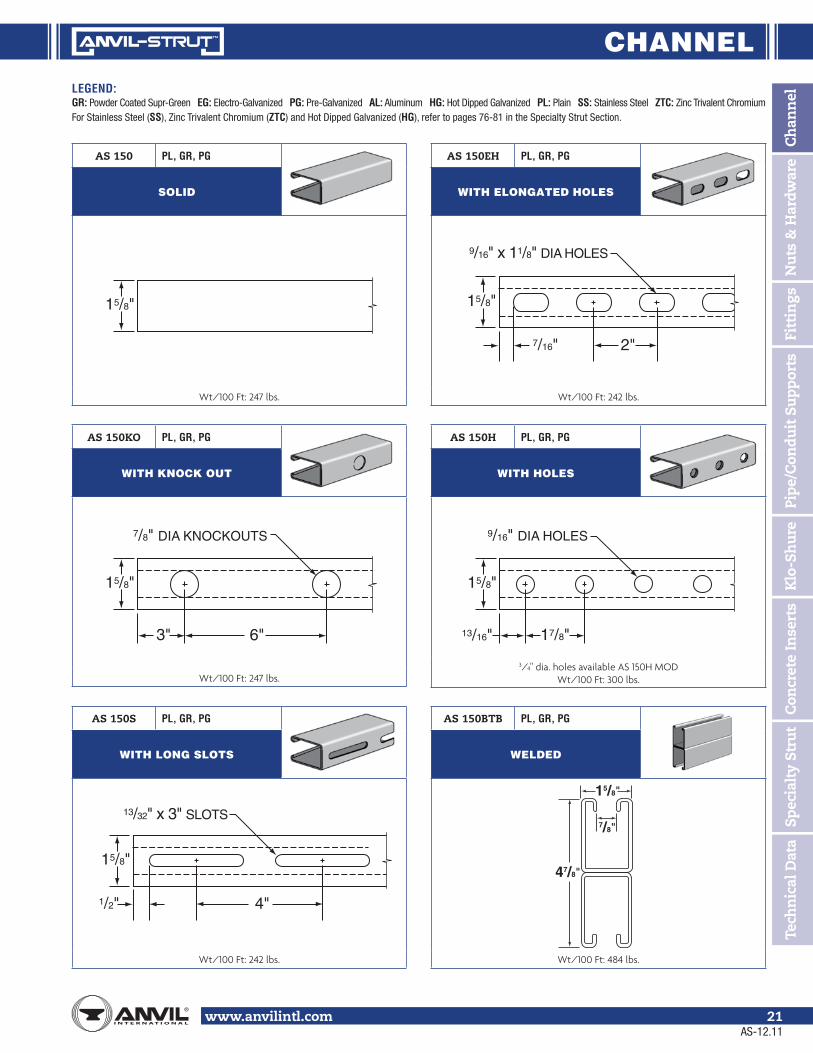
www.anvilintl.com 21
AS 150H PL, GR, PG
WITH HOLES
3/4" dia. holes available AS 150H MODWt/100 Ft: 300 lbs.
AS 150BTB PL, GR, PG
WELDED
Wt/100 Ft: 484 lbs.
AS 150S PL, GR, PG
WITH LONG SLOTS
Wt/100 Ft: 242 lbs.
AS 150 PL, GR, PG
SOLID
Wt/100 Ft: 247 lbs.
AS 150EH PL, GR, PG
WITH ELONGATED HOLES
Wt/100 Ft: 242 lbs.
AS 150KO PL, GR, PG
WITH KNOCK OUT
Wt/100 Ft: 247 lbs.
7/16"
9/16" x 11/8" DIA HOLES
15/8"
2"
1/2"
13/32" x 3" SLOTS
15/8"
4"
3"
7/8" DIA KNOCKOUTS
15/8"
6"
15/8"
17/8"13/16"
9/16" DIA HOLES
15/8"
47/8"
7/8"
15/8"
AS-12.11

CHANNELLEGEND:GR: Powder Coated Supr-Green EG: Electro-Galvanized PG: Pre-Galvanized AL: Aluminum HG: Hot Dipped Galvanized PL: Plain SS: Stainless Steel ZTC: Zinc Trivalent Chromium For Stainless Steel (SS), Zinc Trivalent Chromium (ZTC) and Hot Dipped Galvanized (HG), refer to pages 76-81 in the Specialty Strut Section.
www.anvilintl.com22
AS 20015/8" x 15/8"12 Gauge Channel wt./100 ft. - 194#
Stocked in pre-galvanized, plain and powder coated Supr-Green, in both 10 and 20 ft. lengths. Other materials, finishes and lengths are available upon request.
See page 16 for welded combinations.
X
Y
15/8"(41.28)
7/8"(22.23)
3/8"(9.53)
9/32"(7.14)
15/8"(41.28)
0.923"(23.44)
(mm) millimeters
AS 200 BEAM AND COLUMN LOADS
Span or Column
Anvil-Strut™ Catalog #
Max Load of Column Loaded
@ C.G.
Static Beam Load (X-X Axis)
Allowable Uniform Load @ 25,000 PSI (1758 Kg/cm2)
Deflection @ 25,000 PSI (1758 Kg/cm2)
Uniform Load @ l/240
Uniform Load @ l/360
In mm Lbs kg Lbs kg In mm Lbs kg Lbs kg
12 305 AS 200 7,109 3,225 3,249 1,474 0.014 0.356 ** ** ** **AS 200 BTB 14,862 6,741 2,610 *** 1,184 0.008 0.203 ** ** ** **
18 457 AS 200 6,549 2,971 2,166 982 0.031 0.787 ** ** ** **AS 200 BTB 14,402 6,533 2,610 *** 1,184 0.018 0.457 ** ** ** **
24 610 AS 200 5,938 2,693 1,625 737 0.055 1.397 ** ** ** **AS 200 BTB 13,919 6,314 2,610 *** 1,184 0.032 0.813 ** ** ** **
30 762 AS 200 5,337 2,421 1,300 590 0.086 2.184 ** ** 1,257 570AS 200 BTB 13,473 6,111 2,610 *** 1,184 0.050 1.270 ** ** ** **
36 914 AS 200 4,771 2,164 1,083 481 0.124 3.150 ** ** 873 396AS 200 BTB 13,090 5,938 2,610 *** 1,184 0.072 1.829 ** ** ** **
42 1,067 AS 200 4,242 1,924 928 421 0.169 4.293 ** ** 641 291AS 200 BTB 12,771 5,793 2,610 *** 1,184 0.099 2.515 ** ** ** **
48 1,219 AS 200 3,745 1,699 812 368 0.220 5.588 737 334 491 223AS 200 BTB 12,511 5,675 2,610 *** 1,184 0.129 3.277 ** ** ** **
60 1,524 AS 200 3,012 1,366 650 295 0.344 8.738 471 214 314 142AS 200 BTB 11,685 5,300 1,899 861 0.202 5.131 ** ** 1,566 710
72 1,829 AS 200 2,514 1,140 542 246 0.496 12.598 327 148 218 99AS 200 BTB 10,078 4,571 1,582 718 0.291 7.391 ** ** 1,087 493
84 2,134 AS 200 2,136 969 464 210 0.675 17.145 240 109 160 73AS 200 BTB 8,180 3,710 1,356 615 0.396 10.058 1,199 544 799 362
96 2,438 AS 200 1,834 832 406 184 0.882 22.403 184 83 123 56AS 200 BTB 6,291 2,854 1,187 538 0.517 13.132 917 416 611 277
108 2,743 AS 200 1,585 719 361 164 1.116 28.346 145 66 97 44AS 200 BTB 4,971 2,255 1,055 479 0.655 16.657 725 329 483 219
120 3,048 AS 200 * * 325 147 1.378 35.001 117 53 78 35AS 200 BTB 4,026 1,826 949 430 0.808 20.523 587 266 391 177
180 4,572 AS 200 * * 217 98 3.099 78.715 52 24 35 16AS 200 BTB * * 633 287 1.819 46.203 261 118 174 79
240 6,096 AS 200 * * 163 74 5.510 139.954 29 13 19 9AS 200 BTB * * 474 215 3.233 82.118 147 67 98 44
For Beam and Column Loading Data and load reduction information for channel with holes and concentrated loads, see notes on page 17.
PROPERTIES OF SECTION I = Moment of Inertia S = Section Modulus r = Radius of Gyration
Wt./Ft. Area of Section X-X Axis Y-Y Axis
Lbs kg Sq. In. Sq. Cm. I in4 I cm4 S in3 S cm3 r in. r cm. I in4 I cm4 S in3 S cm3 r in. r cm.AS 200 1.94 0.88 0.544 3.510 0.180 7.492 0.195 3.195 0.575 1.461 0.233 9.698 0.287 4.703 0.655 1.664AS 200BTB 3.88 1.76 1.088 7.019 0.896 37.294 0.570 9.341 0.908 2.306 0.466 19.396 0.574 9.406 0.655 1.664
AS-12.11

CHANNEL
Ch
ann
elN
uts
& H
ardw
are
Fitt
ings
Pipe
/Con
duit
Su
ppor
tsK
lo-S
hu
reC
oncr
ete
Inse
rts
Spec
ialt
y St
rut
Tech
nic
al D
ata
LEGEND:GR: Powder Coated Supr-Green EG: Electro-Galvanized PG: Pre-Galvanized AL: Aluminum HG: Hot Dipped Galvanized PL: Plain SS: Stainless Steel ZTC: Zinc Trivalent Chromium For Stainless Steel (SS), Zinc Trivalent Chromium (ZTC) and Hot Dipped Galvanized (HG), refer to pages 76-81 in the Specialty Strut Section.
www.anvilintl.com 23
1/2"
13/32" x 3" SLOTS
15/8"
4"
AS 200S PL, GR, PG
WITH LONG SLOTS
Wt/100 Ft: 185 lbs.
AS 200 PL, GR, PG
SOLID
Wt/100 Ft: 190 lbs.
AS 200EH PL, GR, PG
WITH ELONGATED HOLES
Wt/100 Ft: 185 lbs.
AS 200KO PL, GR, PG
WITH KNOCK OUT
Wt/100 Ft: 190 lbs.
AS 200H PL, GR, PG
WITH HOLES
3/4" dia. holes available AS 200H MOD Wt/100 Ft: 186 lbs.
17/8"13/16"
9/16" DIA HOLES
15/8"
7/16"
9/16" x 11/8" DIA HOLES
15/8"
2"
3"
7/8" DIA KNOCKOUTS
15/8"
6"
15/8"
AS 200H3 PL, GR, PG
WITH HOLES ON ALL 3 SIDES
Holes on all three sides are 17/8" on center. Wt/100 Ft: 179 lbs.
17/8"13/16"
9/16" DIA HOLES
15/8"
AS-12.11

CHANNELLEGEND:GR: Powder Coated Supr-Green EG: Electro-Galvanized PG: Pre-Galvanized AL: Aluminum HG: Hot Dipped Galvanized PL: Plain SS: Stainless Steel ZTC: Zinc Trivalent Chromium For Stainless Steel (SS), Zinc Trivalent Chromium (ZTC) and Hot Dipped Galvanized (HG), refer to pages 76-81 in the Specialty Strut Section.
www.anvilintl.com24
AS 200STS PL, GR, PG
WELDED
Wt/100 Ft: 380 lbs.
AS 200BTS PL, GR, PG
WELDED
Wt/100 Ft: 380 lbs.
AS 200STSR PL, GR, PG
WELDED
Wt/100 Ft: 380 lbs.
AS 200BTB PL, GR, PG
WELDED
Wt/100 Ft: 380 lbs.
31/4"
7/8"
15/8"
31/4"
7/8"
15/8"
31/4"
7/8"
15/8"
31/4"
7/8"
15/8"
AS 200EH BTB PL, GR, PG
WELDED WITH ELONGATED HOLES
Wt/100 Ft: 370 lbs.
31/4"
7/8"
15/8"
7/16"
9/16" x 11/8" DIA HOLES
15/8"
2"
AS-12.11

CHANNEL
Ch
ann
elN
uts
& H
ardw
are
Fitt
ings
Pipe
/Con
duit
Su
ppor
tsK
lo-S
hu
reC
oncr
ete
Inse
rts
Spec
ialt
y St
rut
Tech
nic
al D
ata
LEGEND:GR: Powder Coated Supr-Green EG: Electro-Galvanized PG: Pre-Galvanized AL: Aluminum HG: Hot Dipped Galvanized PL: Plain SS: Stainless Steel ZTC: Zinc Trivalent Chromium For Stainless Steel (SS), Zinc Trivalent Chromium (ZTC) and Hot Dipped Galvanized (HG), refer to pages 76-81 in the Specialty Strut Section.
www.anvilintl.com 25
AS 21015/8" x 15/8"14 Gauge Channel wt./100 ft. - 145#
Stocked in pre-galvanized, plain and powder coated Supr-Green, in both 10 and 20 ft. lengths. Other materials, finishes and lengths are available upon request.
See page 16 for welded combinations.
X
Y
15/8"(41.28)
7/8"(22.23)
3/8"(9.53)
9/32"(7.14)
15/8"(41.28)
0.905"(22.99)
(mm) millimeters
AS 210 BEAM AND COLUMN LOADS
Span or Column
Anvil-Strut™ Catalog #
Max Load of Column Loaded
@ C.G.
Static Beam Load (X-X Axis)
Allowable Uniform Load @ 25,000 PSI (1758 Kg/cm2)
Deflection @ 25,000 PSI (1758 Kg/cm2)
Uniform Load @ l/240
Uniform Load @ l/360
In mm Lbs kg Lbs kg In mm Lbs kg Lbs kg
12 305 AS 210 5,548 2,517 2,631 1,193 0.014 0.356 ** ** ** **AS 210 BTB 11,600 5,262 1,750 *** 794 0.008 0.203 ** ** ** **
18 457 AS 210 5,066 2,298 1,754 796 0.032 0.813 ** ** ** **AS 210 BTB 11,210 5,085 1,750 *** 794 0.018 0.457 ** ** ** **
24 610 AS 210 4,473 2,029 1,316 597 0.056 1.422 ** ** ** **AS 210 BTB 10,738 4,871 1,750 *** 794 0.032 0.813 ** ** ** **
30 762 AS 210 3,817 1,731 1,052 477 0.088 2.235 ** ** 1,001 454AS 210 BTB 10,230 4,640 1,750 *** 794 0.050 1.270 ** ** ** **
36 914 AS 210 3,141 1,425 877 398 0.126 3.200 ** ** 695 315AS 210 BTB 9,722 4,410 1,750 *** 794 0.072 1.829 ** ** ** **
42 1,067 AS 210 2,546 1,155 752 341 0.172 4.369 ** ** 511 232AS 210 BTB 9,239 4,191 1,750 *** 794 0.098 2.489 ** ** ** **
48 1,219 AS 210 2,148 974 658 298 0.224 5.690 587 266 391 177AS 210 BTB 8,796 3,990 1,750 *** 794 0.128 3.251 ** ** ** **
60 1,524 AS 210 1,659 753 526 239 0.350 8.890 376 171 250 113AS 210 BTB 8,046 3,650 1,482 672 0.200 5.080 ** ** 1,234 560
72 1,829 AS 210 1,370 621 439 199 0.504 12.802 261 118 174 79AS 210 BTB 7,466 3,387 1,235 560 0.288 7.315 ** ** 857 389
84 2,134 AS 210 1,174 533 376 171 0.687 17.450 192 87 128 58AS 210 BTB 6,528 2,961 1,058 480 0.392 9.957 944 428 629 285
96 2,438 AS 210 1,028 466 329 149 0.897 22.784 147 67 98 44AS 210 BTB 5,042 2,287 926 420 0.512 13.005 723 328 482 219
108 2,743 AS 210 911 413 292 132 1.135 28.829 116 53 77 35AS 210 BTB 3,983 1,807 823 373 0.649 16.485 571 259 381 173
120 3,048 AS 210 * * 263 119 1.401 35.585 94 43 63 29AS 210 BTB 3,227 1,464 741 336 0.801 20.345 463 210 308 140
180 4,572 AS 210 * * 175 79 3.153 80.086 42 19 28 13AS 210 BTB 1,434 650 494 224 1.802 45.771 206 93 137 62
240 6,096 AS 210 * * 132 60 5.605 142.367 23 10 16 7AS 210 BTB * * 370 168 3.203 81.356 116 53 77 35
For Beam and Column Loading Data and load reduction information for channel with holes and concentrated loads, see notes on page 17.
PROPERTIES OF SECTION I = Moment of Inertia S = Section Modulus r = Radius of Gyration
Wt./Ft. Area of Section X-X Axis Y-Y Axis
Lbs kg Sq. In. Sq. Cm. I in4 I cm4 S in3 S cm3 r in. r cm. I in4 I cm4 S in3 S cm3 r in. r cm.AS 210 1.45 0.66 0.407 2.626 0.143 5.952 0.158 2.589 0.593 1.506 0.179 7.451 0.221 3.622 0.664 1.687AS 210BTB 2.90 1.32 0.814 5.252 0.706 29.386 0.445 7.292 0.931 2.365 0.359 14.943 0.441 7.227 0.664 1.687
AS-12.11

CHANNELLEGEND:GR: Powder Coated Supr-Green EG: Electro-Galvanized PG: Pre-Galvanized AL: Aluminum HG: Hot Dipped Galvanized PL: Plain SS: Stainless Steel ZTC: Zinc Trivalent Chromium For Stainless Steel (SS), Zinc Trivalent Chromium (ZTC) and Hot Dipped Galvanized (HG), refer to pages 76-81 in the Specialty Strut Section.
www.anvilintl.com26
AS 210BTB PL, GR, PG
WELDED
Wt/100 Ft: 282 lbs.
AS 210S PL, GR, PG
WITH LONG SLOTS
Wt/100 Ft: 137 lbs.
AS 210 PL, GR, PG
SOLID
Wt/100 Ft: 141 lbs.
AS 210EH PL, GR, PG
WITH ELONGATED HOLES
Wt/100 Ft: 137 lbs.
AS 210KO PL, GR, PG
WITH KNOCK OUT
Wt/100 Ft: 141 lbs.
AS 210H PL, GR, PG
WITH HOLES
3/4" dia. holes available AS 210H MOD Wt/100 Ft: 137 lbs.
17/8"13/16"
9/16" DIA HOLES
15/8"
7/16"
9/16" x 11/8" DIA HOLES
15/8"
2"
1/2"
13/32" x 3" SLOTS
15/8"
4"
3"
7/8" DIA KNOCKOUTS
15/8"
6"
15/8"
31/4"
7/8"
15/8"
AS-12.11

CHANNEL
Ch
ann
elN
uts
& H
ardw
are
Fitt
ings
Pipe
/Con
duit
Su
ppor
tsK
lo-S
hu
reC
oncr
ete
Inse
rts
Spec
ialt
y St
rut
Tech
nic
al D
ata
LEGEND:GR: Powder Coated Supr-Green EG: Electro-Galvanized PG: Pre-Galvanized AL: Aluminum HG: Hot Dipped Galvanized PL: Plain SS: Stainless Steel ZTC: Zinc Trivalent Chromium For Stainless Steel (SS), Zinc Trivalent Chromium (ZTC) and Hot Dipped Galvanized (HG), refer to pages 76-81 in the Specialty Strut Section.
www.anvilintl.com 27
AS 30013/8" x 15/8"12 Gauge Channel wt./100 ft. - 176#
Stocked in pre-galvanized, plain and powder coated Supr-Green, in both 10 and 20 ft. lengths. Other materials, finishes and lengths are available upon request.
See page 16 for welded combinations.
X
Y
15/8"(41.28)
7/8"(22.23)
3/8"(9.53)
9/32"(7.14)
0.791"(20.09)
(mm) millimeters
13/8"(34.93)
AS 300 BEAM AND COLUMN LOADS
Span or Column
Anvil-Strut™ Catalog #
Max Load of Column Loaded
@ C.G.
Static Beam Load (X-X Axis)
Allowable Uniform Load @ 25,000 PSI (1758 Kg/cm2)
Deflection @ 25,000 PSI (1758 Kg/cm2)
Uniform Load @ l/240
Uniform Load @ l/360
In mm Lbs kg Lbs kg In mm Lbs kg Lbs kg
12 305 AS 300 6,286 2,851 2,473 1,122 0.016 0.406 ** ** ** **AS 300 BTB 13,094 5,939 2,210 *** 1,002 0.010 0.254 ** ** ** **
18 457 AS 300 5,835 2,647 1,649 748 0.036 0.914 ** ** ** **AS 300 BTB 12,695 5,758 2,210 *** 1,002 0.022 0.559 ** ** ** **
24 610 AS 300 5,371 2,436 1,236 561 0.064 1.626 ** ** ** **AS 300 BTB 12,310 5,584 2,210 *** 1,002 0.038 0.965 ** ** ** **
30 762 AS 300 4,935 2,238 989 449 0.100 2.540 ** ** 820 372AS 300 BTB 11,979 5,434 2,210 *** 1,002 0.060 1.524 ** ** ** **
36 914 AS 300 4,533 2,056 824 374 0.145 3.683 ** ** 570 259AS 300 BTB 11,713 5,313 2,210 *** 1,002 0.086 2.184 ** ** ** **
42 1,067 AS 300 4,157 1,886 707 321 0.197 5.004 628 285 419 190AS 300 BTB 11,503 5,218 2,053 931 0.118 2.997 ** ** 2,035 923
48 1,219 AS 300 3,795 1,721 618 280 0.257 6.528 481 218 320 145AS 300 BTB 11,338 5,143 1,797 815 0.154 3.912 ** ** 1,558 707
60 1,524 AS 300 3,094 1,403 495 225 0.402 10.211 308 140 205 93AS 300 BTB 10,191 4,623 1,437 652 0.240 6.096 ** ** 997 452
72 1,829 AS 300 2,551 1,157 413 187 0.579 14.707 214 97 142 64AS 300 BTB 8,718 3,709 1,198 543 0.346 8.788 1,039 471 692 314
84 2,134 AS 300 2,131 967 353 160 0.788 20.015 157 71 105 48AS 300 BTB 6,978 3,165 1,027 466 0.471 11.963 763 346 509 231
96 2,438 AS 300 1,797 815 309 140 1.029 26.137 120 54 80 36AS 300 BTB 5,347 2,425 898 407 0.615 15.621 584 265 389 176
108 2,743 AS 300 * * 275 125 1.302 33.071 95 43 63 29AS 300 BTB 4,225 1,916 799 362 0.778 19.761 462 210 308 140
120 3,048 AS 300 * * 247 112 1.608 40.843 77 35 51 23AS 300 BTB 3,422 1,552 719 326 0.961 24.409 374 170 249 113
180 4,572 AS 300 * * 165 75 3.618 91.897 34 15 23 10AS 300 BTB * * 479 217 2.162 54.915 166 75 111 50
240 6,096 AS 300 * * 124 56 6.431 163.347 19 8 13 6AS 300 BTB * * 359 163 3.844 97.638 93 42 62 28
For Beam and Column Loading Data and load reduction information for channel with holes and concentrated loads, see notes on page 17.
PROPERTIES OF SECTION I = Moment of Inertia S = Section Modulus r = Radius of Gyration
Wt./Ft. Area of Section X-X Axis Y-Y Axis
Lbs kg Sq. In. Sq. Cm. I in4 I cm4 S in3 S cm3 r in. r cm. I in4 I cm4 S in3 S cm3 r in. r cm.AS 300 1.76 0.80 0.492 3.174 0.117 4.870 0.148 2.425 0.489 1.242 0.203 8.449 0.250 4.097 0.642 1.631AS 300BTB 3.52 1.60 0.983 6.342 0.570 23.725 0.431 7.063 0.762 1.935 0.406 16.899 0.499 8.177 0.642 1.631
AS-12.11

CHANNELLEGEND:GR: Powder Coated Supr-Green EG: Electro-Galvanized PG: Pre-Galvanized AL: Aluminum HG: Hot Dipped Galvanized PL: Plain SS: Stainless Steel ZTC: Zinc Trivalent Chromium For Stainless Steel (SS), Zinc Trivalent Chromium (ZTC) and Hot Dipped Galvanized (HG), refer to pages 76-81 in the Specialty Strut Section.
www.anvilintl.com28
AS 300EH PL, GR, PG
WITH ELONGATED HOLES
Wt/100 Ft: 165 lbs.
AS 300BTB PL, GR, PG
WELDED
Wt/100 Ft: 340 lbs.
AS 300S PL, GR, PG
WITH LONG SLOTS
Wt/100 Ft: 165 lbs.
AS 300 PL, GR, PG
SOLID
Wt/100 Ft: 170 lbs.
AS 300KO PL, GR, PG
WITH KNOCK OUT
Wt/100 Ft: 170 lbs.
AS 300H PL, GR, PG
WITH HOLES
3/4" dia. holes available AS 300H MOD Wt/100 Ft: 165 lbs.
17/8"13/16"
9/16" DIA HOLES
15/8"
7/16"
9/16" x 11/8" DIA HOLES
15/8"
2"
1/2"
13/32" x 3" SLOTS
15/8"
4"
3"
7/8" DIA KNOCKOUTS
15/8"
6"
15/8"
23/4"
7/8"
15/8"
AS-12.11

CHANNEL
Ch
ann
elN
uts
& H
ardw
are
Fitt
ings
Pipe
/Con
duit
Su
ppor
tsK
lo-S
hu
reC
oncr
ete
Inse
rts
Spec
ialt
y St
rut
Tech
nic
al D
ata
LEGEND:GR: Powder Coated Supr-Green EG: Electro-Galvanized PG: Pre-Galvanized AL: Aluminum HG: Hot Dipped Galvanized PL: Plain SS: Stainless Steel ZTC: Zinc Trivalent Chromium For Stainless Steel (SS), Zinc Trivalent Chromium (ZTC) and Hot Dipped Galvanized (HG), refer to pages 76-81 in the Specialty Strut Section.
www.anvilintl.com 29
AS 4001" x 15/8"12 Gauge Channel wt./100 ft. - 149#
Stocked in pre-galvanized, plain and powder coated Supr-Green, in both 10 and 20 ft. lengths. Other materials, finishes and lengths are available upon request.
See page 16 for welded combinations.
0.591"(15.01)
X
Y
15/8"(41.28)
7/8"(22.23)
3/8"(9.53)
9/32"(7.14)
(mm) millimeters
1"(25.40)
AS 400 BEAM AND COLUMN LOADS
Span or Column
Anvil-Strut™ Catalog #
Max Load of Column Loaded
@ C.G.
Static Beam Load (X-X Axis)
Allowable Uniform Load @ 25,000 PSI (1758 Kg/cm2)
Deflection @ 25,000 PSI (1758 Kg/cm2)
Uniform Load @ l/240
Uniform Load @ l/360
In mm Lbs kg Lbs kg In mm Lbs kg Lbs kg
12 305 AS 400 5,046 2,289 1,460 662 0.022 0.559 ** ** ** **AS 400 BTB 10,430 4,731 1,590 *** 721 0.013 0.330 ** ** ** **
18 457 AS 400 4,757 2,158 973 441 0.049 1.245 ** ** ** **AS 400 BTB 10,134 4,597 1,590 *** 721 0.030 0.762 ** ** ** **
24 610 AS 400 4,496 2,039 730 331 0.086 2.184 ** ** 564 256AS 400 BTB 9,897 4,489 1,590 *** 721 0.054 1.371 ** ** ** **
30 762 AS 400 4,264 1,934 584 265 0.135 3.429 541 245 361 164AS 400 BTB 9,723 4,410 1,590 *** 721 0.084 2.134 ** ** 1,698 ** 770
36 914 AS 400 4,047 1,836 487 221 0.194 4.928 376 171 251 114AS 400 BTB 9,599 4,354 1,423 645 0.121 3.073 ** ** 1,179 535
42 1,067 AS 400 3,831 1,738 417 189 0.264 6.706 276 125 184 83AS 400 BTB 9,420 4,273 1,220 553 0.164 4.166 ** ** 866 393
48 1,219 AS 400 3,604 1,635 365 166 0.345 8.763 211 96 141 64AS 400 BTB 8,984 4,075 1,067 484 0.215 5.461 995 451 663 301
60 1,524 AS 400 3,089 1,401 292 132 0.540 13.716 135 61 90 41AS 400 BTB 7,940 3,602 854 387 0.335 8.509 637 289 424 192
72 1,829 AS 400 * * 243 110 0.777 19.736 94 43 63 29AS 400 BTB 6,664 3,023 712 323 0.483 12.268 442 200 295 134
84 2,134 AS 400 * * 209 95 1.058 26.873 69 31 46 21AS 400 BTB 5,167 2,344 610 277 0.657 16.688 325 147 217 98
96 2,438 AS 400 * * 183 83 1.381 35.077 53 24 35 16AS 400 BTB 3,956 1,794 534 242 0.858 21.793 249 113 166 75
108 2,743 AS 400 * * 162 73 1.748 44.399 42 19 28 13AS 400 BTB * * 474 215 1.086 27.584 197 89 131 59
120 3,048 AS 400 * * 146 66 2.158 54.813 34 15 23 10AS 400 BTB * * 427 194 1.341 34.061 159 72 106 48
180 4,572 AS 400 * * 97 44 4.857 123.368 15 7 10 5AS 400 BTB * * 285 129 3.018 76.657 71 32 47 21
240 6,096 AS 400 * * 73 33 8.634 219.304 8 4 6 3AS 400 BTB * * 213 97 5.364 136.246 40 18 27 12
For Beam and Column Loading Data and load reduction information for channel with holes and concentrated loads, see notes on page 17.
PROPERTIES OF SECTION I = Moment of Inertia S = Section Modulus r = Radius of Gyration
Wt./Ft. Area of Section X-X Axis Y-Y Axis
Lbs kg Sq. In. Sq. Cm. I in4 I cm4 S in3 S cm3 r in. r cm. I in4 I cm4 S in3 S cm3 r in. r cm.AS 400 1.49 0.68 0.413 2.665 0.052 2.164 0.088 1.442 0.353 0.897 0.157 6.535 0.194 3.179 0.617 1.567AS 400BTB 2.98 1.35 0.826 5.329 0.243 10.114 0.256 4.195 0.542 1.377 0.315 13.111 0.388 6.358 0.617 1.567
AS-12.11

CHANNELLEGEND:GR: Powder Coated Supr-Green EG: Electro-Galvanized PG: Pre-Galvanized AL: Aluminum HG: Hot Dipped Galvanized PL: Plain SS: Stainless Steel ZTC: Zinc Trivalent Chromium For Stainless Steel (SS), Zinc Trivalent Chromium (ZTC) and Hot Dipped Galvanized (HG), refer to pages 76-81 in the Specialty Strut Section.
www.anvilintl.com30
AS 400BTB PL, GR, PG
WELDED
Wt/100 Ft: 292 lbs.
AS 400S PL, GR, PG
WITH LONG SLOTS
Wt/100 Ft: 141 lbs.
AS 400 PL, GR, PG
SOLID
Wt/100 Ft: 146 lbs.
AS 400EH PL, GR, PG
WITH ELONGATED HOLES
Wt/100 Ft: 141 lbs.
AS 400KO PL, GR, PG
WITH KNOCK OUT
Wt/100 Ft: 146 lbs.
AS 400H PL, GR, PG
WITH HOLES
3/4" dia. holes available AS 400H MOD Wt/100 Ft: 141 lbs.
17/8"13/16"
9/16" DIA HOLES
15/8"
7/16"
9/16" x 11/8" DIA HOLES
15/8"
2"
1/2"
13/32" x 3" SLOTS
15/8"
4"
3"
7/8" DIA KNOCKOUTS
15/8"
6"
15/8"
2"
7/8"
15/8"
AS-12.11

CHANNEL
Ch
ann
elN
uts
& H
ardw
are
Fitt
ings
Pipe
/Con
duit
Su
ppor
tsK
lo-S
hu
reC
oncr
ete
Inse
rts
Spec
ialt
y St
rut
Tech
nic
al D
ata
LEGEND:GR: Powder Coated Supr-Green EG: Electro-Galvanized PG: Pre-Galvanized AL: Aluminum HG: Hot Dipped Galvanized PL: Plain SS: Stainless Steel ZTC: Zinc Trivalent Chromium For Stainless Steel (SS), Zinc Trivalent Chromium (ZTC) and Hot Dipped Galvanized (HG), refer to pages 76-81 in the Specialty Strut Section.
www.anvilintl.com 31
AS 50013/16" x 15/8"14 Gauge Channel wt./100 ft. - 103#
Stocked in pre-galvanized, plain and powder coated Supr-Green, in both 10 and 20 ft. lengths. Other materials, finishes and lengths are available upon request.
See page 16 for welded combinations.
X
Y
15/8"(41.28)
7/8"(22.23)
3/8"(9.53)
9/32"(7.14)
(mm) millimeters
0.472"(11.99)
13/16"(20.64)
AS 500 BEAM AND COLUMN LOADS
Span or Column
Anvil-Strut™ Catalog #
Max Load of Column Loaded
@ C.G.
Static Beam Load (X-X Axis)
Allowable Uniform Load @ 25,000 PSI (1758 Kg/cm2)
Deflection @ 25,000 PSI (1758 Kg/cm2)
Uniform Load @ l/240
Uniform Load @ l/360
In mm Lbs kg Lbs kg In mm Lbs kg Lbs kg
12 305 AS 500 3,598 1,632 887 402 0.027 0.686 ** ** ** **AS 500 BTB 7,434 3,372 870 *** 395 0.016 0.406 ** ** ** **
18 457 AS 500 3,340 1,515 591 268 0.060 1.524 ** ** 493 224AS 500 BTB 7,140 3,239 870 *** 395 0.037 0.940 ** ** ** **
24 610 AS 500 3,086 1,400 444 201 0.106 2.692 416 189 277 126AS 500 BTB 6,867 3,115 870 *** 395 0.066 1.676 ** ** ** **
30 762 AS 500 2,854 1,295 355 161 0.166 4.216 266 121 177 80AS 500 BTB 6,642 3,013 870 *** 395 0.102 2.591 ** ** 806 366
36 914 AS 500 2,645 1,200 296 134 0.240 6.096 185 84 123 56AS 500 BTB 6,466 2,933 826 375 0.147 3.734 ** ** 559 254
42 1,067 AS 500 2,449 1,111 254 115 0.327 8.306 136 62 91 41AS 500 BTB 6,331 2,872 708 321 0.201 5.105 617 280 411 186
48 1,219 AS 500 2,259 1,025 222 101 0.427 10.846 104 47 69 31AS 500 BTB 6,228 2,825 619 281 0.262 6.655 472 214 315 143
60 1,524 AS 500 * * 177 80 0.667 16.942 66 30 44 20AS 500 BTB 5,648 2,562 496 225 0.410 10.414 302 137 201 91
72 1,829 AS 500 * * 148 67 0.960 24.384 46 21 31 14AS 500 BTB 4,711 2,137 413 187 0.590 14.986 210 95 140 64
84 2,134 AS 500 * * 127 58 1.037 26.340 34 15 23 10AS 500 BTB 3,623 1,643 354 161 0.803 20.396 154 70 103 47
96 2,438 AS 500 * * 111 50 1.707 43.358 26 12 17 8AS 500 BTB * * 310 141 1.049 26.645 118 54 79 36
108 2,743 AS 500 * * 99 45 2.160 54.864 21 10 14 6AS 500 BTB * * 275 125 1.328 33.731 93 42 62 28
120 3,048 AS 500 * * 89 40 2.668 67.767 17 8 11 5AS 500 BTB * * 248 112 1.640 41.656 76 34 51 23
180 4,572 AS 500 * * 59 27 6.003 152.476 7 3 5 2AS 500 BTB * * 165 75 3.689 93.701 34 15 23 10
240 6,096 AS 500 * * 44 20 10.672 271.069 4 2 3 1AS 500 BTB * * 124 56 6.560 166.624 19 9 13 6
For Beam and Column Loading Data and load reduction information for channel with holes and concentrated loads, see notes on page 17.
PROPERTIES OF SECTION I = Moment of Inertia S = Section Modulus r = Radius of Gyration
Wt./Ft. Area of Section X-X Axis Y-Y Axis
Lbs kg Sq. In. Sq. Cm. I in4 I cm4 S in3 S cm3 r in. r cm. I in4 I cm4 S in3 S cm3 r in. r cm.AS 500 1.03 0.47 0.286 1.845 0.025 1.041 0.053 0.869 0.298 0.757 0.106 4.412 0.131 2.147 0.610 1.549AS 500BTB 2.06 0.93 0.571 3.684 0.115 4.787 0.149 2.442 0.449 1.140 0.213 8.866 0.262 4.293 0.610 1.549
AS-12.11

CHANNELLEGEND:GR: Powder Coated Supr-Green EG: Electro-Galvanized PG: Pre-Galvanized AL: Aluminum HG: Hot Dipped Galvanized PL: Plain SS: Stainless Steel ZTC: Zinc Trivalent Chromium For Stainless Steel (SS), Zinc Trivalent Chromium (ZTC) and Hot Dipped Galvanized (HG), refer to pages 76-81 in the Specialty Strut Section.
www.anvilintl.com32
AS 500BTB PL, GR, PG
WELDED
Wt/100 Ft: 194 lbs.
AS 500 PL, GR, PG
SOLID
Wt/100 Ft: 97 lbs.
AS 500EH PL, GR, PG
WITH ELONGATED HOLES
Wt/100 Ft: 87 lbs.
AS 500S PL, GR, PG
WITH LONG SLOTS
Wt/100 Ft: 87 lbs.
AS 500H PL, GR, PG
WITH HOLES
3/4" dia. holes available AS 500H MOD Wt/100 Ft: 87 lbs.
17/8"13/16"
9/16" DIA HOLES
15/8"
7/16"
9/16" x 11/8" DIA HOLES
15/8"
2"
1/2"
13/32" x 3" SLOTS
15/8"
4"
15/8"
7/8"
15/8"
15/8"
AS-12.11

CHANNEL
Ch
ann
elN
uts
& H
ardw
are
Fitt
ings
Pipe
/Con
duit
Su
ppor
tsK
lo-S
hu
reC
oncr
ete
Inse
rts
Spec
ialt
y St
rut
Tech
nic
al D
ata
LEGEND:GR: Powder Coated Supr-Green EG: Electro-Galvanized PG: Pre-Galvanized AL: Aluminum HG: Hot Dipped Galvanized PL: Plain SS: Stainless Steel ZTC: Zinc Trivalent Chromium For Stainless Steel (SS), Zinc Trivalent Chromium (ZTC) and Hot Dipped Galvanized (HG), refer to pages 76-81 in the Specialty Strut Section.
www.anvilintl.com 33
AS 52013/16" x 15/8"12 Gauge Channel — wt./100 ft. - 135#
Stocked in pre-galvanized, plain and powder coated Supr-Green, in both 10 and 20 ft. lengths. Other materials, finishes and lengths are available upon request.
See page 16 for welded combinations.
X
Y
15/8"(41.28)
7/8"(22.23)
3/8"(9.53)
9/32"(7.14)
(mm) millimeters
0.492"(12.50)
13/16"(20.64)
AS 520 BEAM AND COLUMN LOADS
Span or Column
Anvil-Strut™ Catalog #
Max Load of Column Loaded
@ C.G.
Static Beam Load (X-X Axis)
Allowable Uniform Load @ 25,000 PSI (1758 Kg/cm2)
Deflection @ 25,000 PSI (1758 Kg/cm2)
Uniform Load @ l/240
Uniform Load @ l/360
In mm Lbs kg Lbs kg In mm Lbs kg Lbs kg
12 305 AS 520 4,423 2,006 1,025 465 0.026 0.660 ** ** ** **AS 520 BTB 9,091 4,124 1,270 *** 576 0.017 0.432 ** ** ** **
18 457 AS 520 4,214 1,911 683 310 0.059 1.499 ** ** 581 264AS 520 BTB 8,857 4,017 1,270 *** 576 0.038 0.965 ** ** ** **
24 610 AS 520 4,039 1,832 513 233 0.105 2.667 490 222 327 148AS 520 BTB 8,693 3,943 1,270 *** 576 0.067 1.702 ** ** ** **
30 762 AS 520 3,882 1,761 410 186 0.163 4.140 313 142 209 95AS 520 BTB 8,585 3,894 1,224 555 0.105 2.667 ** ** 976 443
36 914 AS 520 3,727 1,691 342 155 0.235 5.969 218 99 145 66AS 520 BTB 8,513 3,861 1,020 463 0.150 3.810 1,017 461 678 308
42 1,067 AS 520 3,558 1,614 293 133 0.320 8.128 160 73 107 49AS 520 BTB 8,177 3,709 874 396 0.205 5.207 747 339 498 226
48 1,219 AS 520 3,369 1,528 256 116 0.419 10.643 122 55 81 37AS 520 BTB 7,774 3,526 765 347 0.267 6.782 572 259 381 173
60 1,524 AS 520 * * 205 93 0.654 16.612 78 35 52 24AS 520 BTB 6,807 3,088 612 278 0.418 10.617 366 166 244 111
72 1,829 AS 520 * * 171 78 0.941 23.901 54 24 36 16AS 520 BTB 5,625 2,551 510 231 0.602 15.291 254 115 169 77
84 2,134 AS 520 * * 146 66 1.282 32.563 40 18 27 12AS 520 BTB 4,280 1,941 437 198 0.819 20.803 187 85 125 57
96 2,438 AS 520 * * 128 58 1.674 42.520 31 14 21 10AS 520 BTB * * 382 173 1.070 27.178 143 65 95 43
108 2,743 AS 520 * * 114 52 2.119 53.823 24 11 16 7AS 520 BTB * * 340 154 1.354 34.392 113 51 75 34
120 3,048 AS 520 * * 103 47 2.616 66.446 20 9 13 6AS 520 BTB * * 306 139 1.672 42.469 91 41 61 28
180 4,572 AS 520 * * 68 31 5.887 149.530 9 4 6 3AS 520 BTB * * 204 93 3.762 95.555 41 19 27 12
240 6,096 AS 520 * * 51 23 10.465 265.811 5 2 3 1AS 520 BTB * * 153 69 6.689 169.901 23 10 15 7
For Beam and Column Loading Data and load reduction information for channel with holes and concentrated loads, see notes on page 17.
PROPERTIES OF SECTION I = Moment of Inertia S = Section Modulus r = Radius of Gyration
Wt./Ft. Area of Section X-X Axis Y-Y Axis
Lbs kg Sq. In. Sq. Cm. I in4 I cm4 S in3 S cm3 r in. r cm. I in4 I cm4 S in3 S cm3 r in. r cm.AS 520 1.374 0.623 0.374 2.413 0.030 1.249 0.062 1.016 0.283 0.719 0.135 5.619 0.166 2.720 0.600 1.524AS 520BTB 2.700 1.225 0.748 4.826 0.140 5.827 0.184 3.015 0.432 1.097 0.270 11.238 0.332 5.441 0.600 1.524
AS-12.11

CHANNELLEGEND:GR: Powder Coated Supr-Green EG: Electro-Galvanized PG: Pre-Galvanized AL: Aluminum HG: Hot Dipped Galvanized PL: Plain SS: Stainless Steel ZTC: Zinc Trivalent Chromium For Stainless Steel (SS), Zinc Trivalent Chromium (ZTC) and Hot Dipped Galvanized (HG), refer to pages 76-81 in the Specialty Strut Section.
www.anvilintl.com34
AS 520BTB PL, GR, PG
WELDED
Wt/100 Ft: 256 lbs.
AS 520 PL, GR, PG
SOLID
Wt/100 Ft: 128 lbs.
AS 520EH PL, GR, PG
WITH ELONGATED HOLES
Wt/100 Ft: 123 lbs.
AS 520S PL, GR, PG
WITH LONG SLOTS
Wt/100 Ft: 118 lbs.
AS 520H PL, GR, PG
WITH HOLES
3/4" dia. holes available AS 520H MOD Wt/100 Ft: 123 lbs.
17/8"13/16"
9/16" DIA HOLES
15/8"
7/16"
9/16" x 11/8" DIA HOLES
15/8"
2"
1/2"
13/32" x 3" SLOTS
15/8"
4"
15/8"
7/8"
15/8"
15/8"
AS-12.11

CHANNEL
Ch
ann
elN
uts
& H
ardw
are
Fitt
ings
Pipe
/Con
duit
Su
ppor
tsK
lo-S
hu
reC
oncr
ete
Inse
rts
Spec
ialt
y St
rut
Tech
nic
al D
ata
LEGEND:GR: Powder Coated Supr-Green EG: Electro-Galvanized PG: Pre-Galvanized AL: Aluminum HG: Hot Dipped Galvanized PL: Plain SS: Stainless Steel ZTC: Zinc Trivalent Chromium For Stainless Steel (SS), Zinc Trivalent Chromium (ZTC) and Hot Dipped Galvanized (HG), refer to pages 76-81 in the Specialty Strut Section.
www.anvilintl.com 35
AS 56013/16" x 15/8"16 Gauge Channel — wt./100 ft. - 135#
Stocked in pre-galvanized, plain and powder coated supr-green, in both 10 and 20 ft. lengths. Other materials, finishes and lengths are available upon request.
X
Y
15/8"(41.28)
7/8"(22.23)
3/8"(9.53)
1/4"(6.35)
(mm) millimeters
0.343"(8.71)
13/16"(20.64)
AS 560 BEAM AND COLUMN LOADS
Span or Column
Anvil-Strut™ Catalog #
Max Load of Column Loaded
@ C.G.
Static Beam Load (X-X Axis)
Allowable Uniform Load @ 25,000 PSI (1758 Kg/cm2)
Deflection @ 25,000 PSI (1758 Kg/cm2)
Uniform Load @ l/240
Uniform Load @ l/360
In mm Lbs kg Lbs kg In mm Lbs kg Lbs kg
12 305 AS 560 4,820 2,186 800 363 0.03 0.76 ** ** ** **18 457 AS 560 4,320 1,960 540 245 0.06 1.52 ** ** 450 20424 610 AS 560 3,610 1,637 400 181 0.11 2.79 380 172 250 11330 762 AS 560 2,700 1,225 320 145 0.17 4.32 240 109 160 5336 914 AS 560 1,880 853 270 122 0.24 6.10 170 77 110 5042 1,067 AS 560 1,380 626 230 104 0.33 8.38 120 54 80 3648 1,219 AS 560 1,060 481 200 91 0.43 10.92 90 41 60 2754 1,372 AS 560 830 376 180 82 0.54 13.72 70 32 50 2360 1,524 AS 560 680 308 160 73 0.67 17.02 60 27 40 1866 1,676 AS 560 * * 150 68 0.81 20.57 50 23 30 1472 1,829 AS 560 * * 130 59 0.96 24.38 40 18 30 1484 2,134 AS 560 * * 110 50 1.31 33.27 30 14 20 996 2,438 AS 560 * * 100 45 1.71 43.43 20 9 20 9108 2,743 AS 560 * * 90 41 2.16 54.86 20 9 10 5120 3,048 AS 560 * * 80 36 2.67 67.82 20 9 10 5
For Beam and Column Loading Data and load reduction information for channel with holes and concentrated loads, see notes on page 17.
PROPERTIES OF SECTION I = Moment of Inertia S = Section Modulus r = Radius of Gyration
Wt./Ft. Area of Section X-X Axis Y-Y Axis
Lbs kg Sq. In. Sq. Cm. I in4 I cm4 S in3 S cm3 r in. r cm. I in4 I cm4 S in3 S cm3 r in. r cm.AS 560 0.810 0.367 0.239 1.542 0.023 0.957 0.048 0.787 0.308 0.782 0.091 3.788 0.112 1.835 0.617 1.567
AS-12.11

CHANNELLEGEND:GR: Powder Coated Supr-Green EG: Electro-Galvanized PG: Pre-Galvanized AL: Aluminum HG: Hot Dipped Galvanized PL: Plain SS: Stainless Steel ZTC: Zinc Trivalent Chromium For Stainless Steel (SS), Zinc Trivalent Chromium (ZTC) and Hot Dipped Galvanized (HG), refer to pages 76-81 in the Specialty Strut Section.
www.anvilintl.com36
AS 560 PL, GR, PG
SOLID
Wt/100 Ft: 81 lbs.
AS 560EH PL, GR, PG
WITH ELONGATED HOLES
Wt/100 Ft: 81 lbs.
AS 707P GR, Grey, White
METAL PAINTED CLOSURE STRIP
Wt/100 Ft: 10 lbs.
AS 707 GR, PG
METAL RACEWAY CLOSURE STRIP
Wt/100 Ft: 47 lbs.
7/16"
9/16" x 11/8" DIA HOLES
15/8"
2"
15/8"
15/8"
.040"
15/8"
.040"
AS-12.11

CHANNEL NUTS & HARDWARE
Ch
ann
elN
uts
& H
ardw
are
Fitt
ings
Pipe
/Con
duit
Su
ppor
tsK
lo-S
hu
reC
oncr
ete
Inse
rts
Spec
ialt
y St
rut
Tech
nic
al D
ata
www.anvilintl.com 37
Cat. No. Size Thd. Thk. Wt/100 pcs ChannelAS LS 1/4" 20 1/4" 7
AS 100, AS 150
AS LS 3/8" 16 3/8" 10AS LS 1/2" 13 3/8" 10AS LS 1/2" 13 1/2" 13AS LS 5/8" 11 7/16" 23AS LS 3/4" 10 7/16" 20AS LS 5/16" 18 3/8" 7
Cat. No. Size Thd. Thk. Wt/100 pcs ChannelAS NS 1/4" 20 1/4" 6
All Anvil-Strut™
AS NS 3/8" 16 3/8" 9AS NS 1/2" 13 1/2" 12
AS 100, AS 150, AS 200, AS 210,AS 300, AS 500
AS NS 5/8" 11 7/16" 20AS NS 3/4" 10 7/16" 18AS NS 7/8" 9 7/16" 16AS NS 5/8" 11 7/16" 20
All Anvil-Strut™
AS NS 3/4" 10 7/16" 18AS NS S 1/2" 13 3/16" 14
All Anvil-Strut™AS NS S 5/8" 11 3/16" 14AS NS S 3/4" 10 3/16" 7
Cat. No. Size Thd. Thk. Wt/100 pcs ChannelAS RS 1/4" 20 1/4" 7
AS 200, AS 210,AS 300
AS RS 3/8" 16 3/8" 10AS RS 1/2" 13 1/2" 13AS RS 5/8" 11 7/16" 23AS RS 3/4" 10 7/16" 20AS RS 7/8" 9 7/16" 17
Cat. No. Size Thd. Thk. Wt/100 pcs ChannelAS SS 1/4" 20 1/4" 7
AS 400, AS 500
AS SS 3/8" 16 3/8" 9AS SS 1/2" 13 3/8" 9AS SS 5/8" 11 3/8" 10AS SS 3/4" 10 3/8" 9AS SS 5/16" 18 3/8" 7
Cat. No. Size Thd. Thk. Wt/100 pcs ChannelAS TG 1/4" 20 1/4" 6
All Anvil-Strut™AS TG 3/8" 16 3/8" 9AS TG 1/2" 13 3/8" 9AS TG 5/16" 18 3/8" 7
SPECIFICATIONS
GENERAL
Anvil-Strut™ Grip Lock Nuts are designed with specially formed teeth in the parallel channel recesses to grip the returned lip of the channel. The shearing action of the teeth assures positive locking of the Anvil-Strut™ channels to the fittings.
MATERIAL
Anvil-Strut™ Grip Lock Nuts are manufactured from mild steel bars, and are case hardened to a depth of .003” to .005” after machining, conforming to ASTM A576 GR1015. Selected sizes also available in Stainless Steel.
FINISH
All Anvil-Strut™ Grip Lock Nuts and Hardware have an electro-galvanized finish (ASTM-B-633 BSCI), unless otherwise noted.
INSTALLATION
Notes
1. Safety Factor of 3.
2. 1/2"- 13 Bolt tightened to 50 Ft.-Lbs. torque.
3. Follow recommended bolt torque values (see technical data section chart)
ORDERING
On the Anvil-Strut™ Grip Lock Nuts, consult the selection table which shows the correct locking nut for each size channel. On the Hardware please specify the diameter or size required, and length where applicable.
1/2" DIA. BOLT & GRIP LOCK NUT LOAD DATA (LBS)Resistance to Slip Pull Out Strength
12 Gauge - 1,400 12 Gauge - 2,00014 Gauge - 1,100 14 Gauge - 1,14015 Gauge - 1,100 15 Gauge - 1,100
DATA: The selection table shows the correct locking nuts for each size channel.
Long Spring
Without Spring
Regular Spring
Short Spring
Top Grip
AS-12.11

CHANNEL NUTS & HARDWARELEGEND:GR: Powder Coated Supr-Green EG: Electro-Galvanized PG: Pre-Galvanized AL: Aluminum HG: Hot Dipped Galvanized PL: Plain SS: Stainless Steel ZTC: Zinc Trivalent Chromium For Stainless Steel (SS) and Zinc Trivalent Chromium (ZTC), refer to page 82 in the Specialty Strut Section.
www.anvilintl.com38
AS LS EG
CLAMPING NUT WITH LONG SPRING
Use With AS 100 and AS 150 Channel.
Std Pkg: 50 · Wt/100 pcs: See chart above.
AS NS EG, SS, ZTC
CLAMPING NUT WITHOUT SPRING
Use With All 15/8" Wide Channel.
Std Pkg: 100 · Wt/100 pcs: See chart above.
AS TG EG
TOP GRIP NUT WITH SPRING ON TOP
Use With All 15/8" Channel.
Std Pkg: 100 · Wt/100 pcs: See chart above.
AS 517 EG
STUD NUT WITH RS SPRING
Std Pkg: 100 · Wt/100 pcs: See chart above.
AS RS EG, SS, ZTC
CLAMPING NUT WITH REGULAR SPRING
Use With AS 200, AS 210 and AS 300 Channel.
Std Pkg: 100 · Wt/100 pcs: See chart above.
AS SS EG
CLAMPING NUT WITH SHORT SPRING
Use With AS 400 and AS 500 Channel.
Std Pkg: 100 · Wt/100 pcs: See chart above.
Size Wt/100 pcs1/4" x 20 7.13/8" x 16 9.91/2" x 13 11.95/8" x 11 15.53/4" x 10 13.87/8" x 9 14.3
Size Wt/100 pcs#8 x 32 7.0
#10 x 24 7.0#10 x 32 7.01/4" x 20 6.95/16" 18 6.7
3/8" x 16 9.61/2" x 13 8.85/8" x 11 11.5
Size Wt/100 pcs
AS NS
1/4" x 20 6.63/8" x 16 9.31/2" x 13 11.45/8" x 11 15.23/4" x 10 13.07/8" x 10 14.07/8" x 10 14.0
AS NS S
1/4" x 20 7.01/2" x 13 14.05/8" x 11 14.03/4" x 10 7.0
Size Wt/100 pcs1/4" x 20 7.53/8" x 16 10.21/2" x 13 12.35/8" x 11 15.83/4" x 10 14.1
Size Wt/100 pcs1/4" x 20 7.03/8" x 16 10.01/2" x 13 8.0
5/16" x 18 size available as POA.
Size Wt/100 pcs1/4" x 1" 8.1
1/4" x 11/4" 8.31/4" x 11/2" 8.6
1/4" x 2" 9.13/8" x 1" 13.0
3/8" x 11/4" 14.03/8" x 11/2" 14.0
3/8" x 2" 15.01/2" x 1" 15.0
1/2" x 11/4" 16.01/2" x 11/2" 17.0
1/2" x 2" 19.0
AS-12.11

CHANNEL NUTS & HARDWARELEGEND:GR: Powder Coated Supr-Green EG: Electro-Galvanized PG: Pre-Galvanized AL: Aluminum HG: Hot Dipped Galvanized PL: Plain SS: Stainless Steel ZTC: Zinc Trivalent Chromium For Stainless Steel (SS) and Zinc Trivalent Chromium (ZTC), refer to page 82 in the Specialty Strut Section.
Ch
ann
elN
uts
& H
ardw
are
Fitt
ings
Pipe
/Con
duit
Su
ppor
tsK
lo-S
hu
reC
oncr
ete
Inse
rts
Spec
ialt
y St
rut
Tech
nic
al D
ata
www.anvilintl.com 39
AS 3281 EG
DOUBLE CONVEYOR ADJUSTING NUT
Use For All 15/8" Wide Anvil-Strut™ Channels.
Size = 3/5" Threads: 16
Wt/100 pcs: 17.5 lbs.
AS 83 EG
HEXAGON NUT
Std Pkg & Wt/100 pcs: See chart above.
AS 203 EG
LINKED EYELET WITH STUD
Max. Load: 610 lbs.
Std Pkg & Wt/100 pcs: See chart above.
AS 209 EG
FLAT WASHER
Std Pkg & Wt/100 pcs: See chart above.
Fig. 135
ROD COUPLING
For additional information, please refer to the Anvil Pipe Hanger Catalog.
Fig. 146
CONTINUOUS THREADED ROD
For additional information, please refer to the Anvil Pipe Hanger Catalog.
Size Std Pkg Wt/100 pcs1/4" 500 0.73/8" 500 1.61/2" 100 3.85/8 50 7.3
3/4" 50 11.9
Size Std Pkg Wt/100 pcs3/8" 100 27.01/2" 50 45.0
Size Std Pkg Wt/100 pcs1/4" 200 0.73/8" 100 1.51/2" 100 3.95/8 100 7.7
3/4" 100 11.0
AS-12.11

CHANNEL NUTS & HARDWARELEGEND:GR: Powder Coated Supr-Green EG: Electro-Galvanized PG: Pre-Galvanized AL: Aluminum HG: Hot Dipped Galvanized PL: Plain SS: Stainless Steel ZTC: Zinc Trivalent Chromium For Stainless Steel (SS) and Zinc Trivalent Chromium (ZTC), refer to page 82 in the Specialty Strut Section.
www.anvilintl.com40
AS 211 EG
LOCK WASHER
Std Pkg & Wt/100 pcs: See chart above.
AS 230 EG
FENDER WASHER
Std Pkg & Wt/100 pcs: See chart above.
AS 3500 EG, ZTC
SEISMIC ROD STIFFENER
Size = 3/8" -5/8"
Std Pkg: 25 · Wt/100 pcs: 16.0 lbs.
AS 6024 EG
HEX HEAD CAP SCREW
Std Pkg & Wt/100 pcs: See chart above.
AS 6075 EG
SLOTTED HEX HEAD MACHINE SCREW
Std Pkg & Wt/100 pcs: See chart above.
AS 6108 EG
SQUARE NUT
Std Pkg & Wt/100 pcs: See chart above.
Size Std Pkg Wt/100 pcs1/4" 100 0.33/8" 100 0.71/2" 100 1.5
Size Std Pkg Wt/100 pcs1/4" 100 3.33/8" 100 3.01/2" 100 2.8
Size Std Pkg Wt/100 pcs1/4" 100 0.95/16" 100 1.63/8" 100 2.61/2" 100 5.8
Size Std Pkg Wt/100 pcs1/4" x 3/4" 100 1.75/16" x 1" 100 2.6
5/16" x 11/4" 100 3.05/16" x 11/2" 100 3.43/8" x 11/4" 100 5.3
Size Std Pkg Wt/100 pcs1/4" x 3/4" 100 1.51/4" x 1" 100 1.8
1/4" x 11/4" 100 2.11/4" x 11/2" 100 2.4
3/8" x 3/4" 100 3.63/8" x 1" 100 4.2
3/8" x 11/4" 100 4.93/8" x 11/2" 100 5.6
3/8" x 2" 100 7.21/2" x 3/4" 100 8.11/2" x 1" 100 9.2
1/2" x 11/4" 100 10.41/2" x 11/2" 100 11.61/2" x 13/4" 100 13.0
1/2" x 2" 100 14.4
AS-12.11

FITTINGSLEGEND:GR: Powder Coated Supr-Green EG: Electro-Galvanized PG: Pre-Galvanized AL: Aluminum HG: Hot Dipped Galvanized PL: Plain SS: Stainless Steel ZTC: Zinc Trivalent Chromium For Zinc Trivalent Chromium (ZTC), refer to pages 82-88 in the Specialty Strut Section. For Load Rating, see page 94.
Ch
ann
elN
uts
& H
ardw
are
Fitt
ings
Pipe
/Con
duit
Su
ppor
tsK
lo-S
hu
reC
oncr
ete
Inse
rts
Spec
ialt
y St
rut
Tech
nic
al D
ata
www.anvilintl.com 41
AS 85 EG
ROD OR INSULATOR SUPPORT
Std Pkg & Wt/100 pcs: See chart above.
B
A
Fig. 86
CLAMP WITH LOCK NUT
Size Range 3/8" thru 3/4".
For additional information, please refer to the Anvil Pipe Hanger Catalog.
Fig. 93
TOP BEAM “C” CLAMP
Size Range 3/8" thru 1/2".
For additional information, please refer to the Anvil Pipe Hanger Catalog.
Fig. 95
CLAMP WITH LOCK NUT
Size Range 3/8" thru 3/4".
For additional information, please refer to the Anvil Pipe Hanger Catalog.
Fig. 94
TOP BEAM “C” CLAMP
Size Range 5/8" thru 3/4".
For additional information, please refer to the Anvil Pipe Hanger Catalog.
AS 135X EG
BEAM CLAMP LIGHT DUTY
Size = 1/4"Load Rating: 75 lbs.
Std Pkg: 50 · Wt/100 pcs: 14.0 lbs.
Rod Size A B Load
Rating Std Pkg Wt/ 100 pcs
1/4" 11/8" 11/4" 150 50 233/8" 2" 2" 350 25 951/2" 25/8" 21/2" 400 25 195
AS-12.11

FITTINGSLEGEND:GR: Powder Coated Supr-Green EG: Electro-Galvanized PG: Pre-Galvanized AL: Aluminum HG: Hot Dipped Galvanized PL: Plain SS: Stainless Steel ZTC: Zinc Trivalent Chromium For Zinc Trivalent Chromium (ZTC), refer to pages 82-88 in the Specialty Strut Section. For Load Rating, see page 94.
www.anvilintl.com42
31/2"
15/8"
AS 611 GR, EG, ZTC
“Z” SUPPORT
Use With AS 200, AS 210, and AS 500BTB.
Std Pkg: 50 · Wt/100 pcs: 55 lbs.
2"
33/4"
21/4"
15/8"
AS 604 GR, EG, ZTC
TWO HOLE CORNER ANGLE
Std Pkg: 50 · Wt/100 pcs: 38 lbs.
AS 605 GR, EG, ZTC
THREE HOLE CORNER ANGLE
Std Pkg: 25 · Wt/100 pcs: 58 lbs.
AS 601 GR, EG, ZTC
TWO HOLE SPLICE PLATE
Std Pkg: 50 · Wt/100 pcs: 38 lbs.
AS 602 GR, EG, ZTC
THREE HOLE SPLICE PLATE
Std Pkg: 25 · Wt/100 pcs: 50 lbs.
AS 603 GR, EG, ZTC
TWO HOLE END ANGLE
Std Pkg: 50 · Wt/100 pcs: 38 lbs.
AS 607 GR, EG, ZTC
FOUR HOLE CORNER ANGLE
Std Pkg: 25 · Wt/100 pcs: 78 lbs.
AS 606 GR, EG, ZTC
THREE HOLE CORNER ANGLE
Std Pkg: 25 · Wt/100 pcs: 58 lbs.
AS 609 GR, EG
TWO HOLE OFFSET “Z” SUPPORT
Std Pkg: 25 · Wt/100 pcs: 38 lbs.
31/2"53/8"
2"
17/8"
41/8"
15/8"
41/8"
31/2"
315/32"
1/4"
15/8"
AS-12.11

FITTINGSLEGEND:GR: Powder Coated Supr-Green EG: Electro-Galvanized PG: Pre-Galvanized AL: Aluminum HG: Hot Dipped Galvanized PL: Plain SS: Stainless Steel ZTC: Zinc Trivalent Chromium For Zinc Trivalent Chromium (ZTC), refer to pages 82-88 in the Specialty Strut Section. For Load Rating, see page 94.
Ch
ann
elN
uts
& H
ardw
are
Fitt
ings
Pipe
/Con
duit
Su
ppor
tsK
lo-S
hu
reC
oncr
ete
Inse
rts
Spec
ialt
y St
rut
Tech
nic
al D
ata
www.anvilintl.com 43
513/32"
(A) I.D.
AS 613 GR, EG, ZTC
“U” SUPPORT
Use With AS 200, AS 210, and AS 500BTB.
A = 15/8"
Std Pkg: 25 · Wt/100 pcs: 88 lbs.
AS 615 GR, EG
FIVE HOLE SHELF JOINT ANGLE CONNECTOR
Std Pkg: 10 · Wt/100 pcs: 135 lbs.
31/2"
“A”
AS 612 GR, EG
“Z” SUPPORT
Use With AS 400.
A = 1"
Std Pkg: 50 · Wt/100 pcs: 47 lbs.
AS 614 GR, EG
FOUR HOLE JOINT ANGLE CONNECTOR
Std Pkg: 25 · Wt/100 pcs: 103 lbs.
AS 619 GR, EG, SS, ZTC
SQUARE WASHER
Std Pkg: 100 · Wt/100 pcs: See chart above.
AS 616 GR, EG, ZTC
FOUR HOLE SPLICE CLEVIS
Use With AS 200 and AS 210.
Std Pkg: 10 · Wt/100 pcs: 265 lbs.
AS 617 GR, EG
THREE HOLE SWIVEL PLATE
Std Pkg: 25 · Wt/100 pcs: 75 lbs.
AS 620 GR, EG
TWO HOLE CONNECTING PLATE
Std Pkg: 50 · Wt/100 pcs: 35 lbs.
A Wt/100 pcs1/4" 183/8" 181/2 175/8 163/4 157/8 –
21/4"
31/2"
31/2"
37/8"
31/2"
31/2"
71/4"
71/8"
35/8"17/8"
13/16"
13/16"
15/8" 15/8"
BoltSize “A”
31/4"
Holes C to C15/8"
AS-12.11

FITTINGSLEGEND:GR: Powder Coated Supr-Green EG: Electro-Galvanized PG: Pre-Galvanized AL: Aluminum HG: Hot Dipped Galvanized PL: Plain SS: Stainless Steel ZTC: Zinc Trivalent Chromium For Zinc Trivalent Chromium (ZTC), refer to pages 82-88 in the Specialty Strut Section. For Load Rating, see page 94.
www.anvilintl.com44
71/4"
AS 633 GR, EG, ZTC
TWO HOLE OPEN ANGLE CONNECTOR
Std Pkg: 25 · Wt/100 pcs: See chart above.
AS 624 GR, EG, ZTC
TWO HOLE CLOSED ANGLE CONNECTOR
Std Pkg: 25 · Wt/100 pcs: See chart above.
AS 629 GR, EG
THREE HOLE SPLICE CLEVIS
Use With AS 200, AS 210.
Std Pkg: 20 · Wt/100 pcs: 197 lbs.
AS 631 GR, EG
TWO HOLE SPLICE CLEVIS
Use With AS 200, AS 210.
Std Pkg: 25 · Wt/100 pcs: 128 lbs.
AS 644 GR, EG
TWO HOLE SPLICE CLEVIS
Use With AS 500, AS 520.
Std Pkg: 20 · Wt/100 pcs: 85 lbs.
AS 645 GR, EG
THREE HOLE SPLICE CLEVIS
Use With AS 500, AS 520.
Std Pkg: 10 · Wt/100 pcs: 130 lbs.
AS 646 GR, EG
FOUR HOLE SPLICE CLEVIS
Use With AS 500, AS 520.
Std Pkg: 10 · Wt/100 pcs: 176 lbs.
Angle A Wt/100 pcs37 1/2° 58
45° 5852 1/2° 58
60° 5867 1/2° 58
75° 5882 1/2° 58
Angle A Wt/100 pcs82 1/2° 58
75° 5867 1/2° 58
60° 5852 1/2° 58
45° 5837 1/2° 58
30° 5822 1/2° 58
15° 587 1/2° 58
31/2"
21/2"
A
53/8"
31/2"
23/8"
31/4"
A
31/2" 53/8"
AS-12.11

FITTINGSLEGEND:GR: Powder Coated Supr-Green EG: Electro-Galvanized PG: Pre-Galvanized AL: Aluminum HG: Hot Dipped Galvanized PL: Plain SS: Stainless Steel ZTC: Zinc Trivalent Chromium For Zinc Trivalent Chromium (ZTC), refer to pages 82-88 in the Specialty Strut Section. For Load Rating, see page 94.
Ch
ann
elN
uts
& H
ardw
are
Fitt
ings
Pipe
/Con
duit
Su
ppor
tsK
lo-S
hu
reC
oncr
ete
Inse
rts
Spec
ialt
y St
rut
Tech
nic
al D
ata
www.anvilintl.com 45
AS 655, AS 656 PG
TYPE “A” END CAP
Use With AS 200 Channel. Use With AS 300 Channel and AS 349 Insert.
AS 655: A = 15/8"AS 656: A = 13/8"
Std Pkg: 100 · Wt/100 pcs: (655, 656) 11, 15 lbs.
A
31/2"
13/16"
1/4"
A
AS 661 T2 GRAS 661 T1 GR
31/2"
13/16"
1/4"
A
AS 651 GR, EG, ZTC
REVERSIBLE STRUT BRACKET
Std Pkg: Bulk · Wt/100 pcs: See chart above.
AUniform Load*
(Lbs)
Conc. Load at End*
(Lbs)Wt/100 pcs
6" 1200 425 18512" 600 235 29318" 400 165 40124" 300 125 509
* Mounted on 12 Ga. Channel
AS 665 GR, EG, ZTC
FOUR HOLE DOUBLE CORNER CONNECTOR
Std Pkg: 25 · Wt/100 pcs: 76 lbs.
AS 666 GR, EG, ZTC
SIX HOLE DOUBLE CORNER CONNECTOR
Std Pkg: 25 · Wt/100 pcs: 115 lbs.
AS 667 GR, EG, ZTC
EIGHT HOLE DOUBLE CORNER CONNECTOR
Std Pkg: 10 · Wt/100 pcs: 155 lbs.
45/8"
AS 200
A
9/16" dia. holes
Std Pkg: BulkWt/100 pcs: See chart above.
Std Pkg: BulkWt/100 pcs: See chart above.
31/2"
21/16"
37/8"
17/8"
53/8"
315/16"
AUniform Load*
(Lbs)
Conc. Load at End*
(Lbs)Wt/100 pcs
6" 1600 565 19112" 800 310 29218" 600 245 43624" 450 185 536
* Mounted on 12 Ga. Channel
AUniform Load*
(Lbs)
Conc. Load at End*
(Lbs)Wt/100 pcs
6" 1600 565 19112" 800 310 29218" 600 245 43624" 450 185 536
* Mounted on 12 Ga. Channel
AS-12.11

FITTINGSLEGEND:GR: Powder Coated Supr-Green EG: Electro-Galvanized PG: Pre-Galvanized AL: Aluminum HG: Hot Dipped Galvanized PL: Plain SS: Stainless Steel ZTC: Zinc Trivalent Chromium For Zinc Trivalent Chromium (ZTC), refer to pages 82-88 in the Specialty Strut Section. For Load Rating, see page 94.
www.anvilintl.com46
AS 678 GR, EG
THREE HOLE “U” SUPPORT
Use With AS 150 BTB.
Std Pkg: 10 · Wt/100 pcs: 197 lbs.
15/8"
3/8"
7/8"
11/2"2 Holes 9/16" Diam.
1/2" - 13 x 11/2"
Set Screw included
3/8"
1/2// " 3 x - 13 11/2// "
ncludedSet Screw in
31/4// "
1"
AS 684 GR, EG
BEAM CLAMP
Includes Cup Point Set Screw.
Load Rating: 500 lbs.
Std Pkg: 25 · Wt/100 pcs: 94 lbs.
47/8"
17/8"
31/2"
53/8"
21/16"
AS 685 GR, EG
BEAM CLAMP
Includes Cup Point Set Screw.
Load Rating: 450 lbs.
Std Pkg: 20 · Wt/100 pcs: 63 lbs.
AS 669 GR, EG, ZTC
TWELVE HOLE THREE ANGLE CLEVIS CONNECTOR
Std Pkg: 10 · Wt/100 pcs: 230 lbs.
AS 677 GR, EG
CUP SUPPORT FOR STANDARD SINGLE STRUT
Use With AS 200 and AS 210.
Std Pkg: 25 · Wt/100 pcs: 76 lbs.
AS 679 GR, EG, ZTC
“U” SUPPORT
Use For AS 100, AS 200BTB, AS 210BTB.
A = 31/4"
Std Pkg: 25 · Wt/100 pcs: 128 lbs.
AS 686 GR, EG
BEAM CLAMP
Order AS 6024 1/2" x 1 1/2" Separately.
*Load Rating: 600 lbs.
Std Pkg: 50 · Wt/100 pcs: 26 lbs.
* When used with 12 Ga. Channel. 14 Ga. Channel is 500 lbs.
31/2"
91/4"
315/16"
15/64"41/32"
15/8"
513/32"
(A) I.D.
15/8"
23/8"
AS 668 GR, EG, ZTC
SIX HOLE THREE ANGLE CONNECTOR
Std Pkg: 10 · Wt/100 pcs: 113 lbs.
AS-12.11

FITTINGSLEGEND:GR: Powder Coated Supr-Green EG: Electro-Galvanized PG: Pre-Galvanized AL: Aluminum HG: Hot Dipped Galvanized PL: Plain SS: Stainless Steel ZTC: Zinc Trivalent Chromium For Zinc Trivalent Chromium (ZTC), refer to pages 82-88 in the Specialty Strut Section. For Load Rating, see page 94.
Ch
ann
elN
uts
& H
ardw
are
Fitt
ings
Pipe
/Con
duit
Su
ppor
tsK
lo-S
hu
reC
oncr
ete
Inse
rts
Spec
ialt
y St
rut
Tech
nic
al D
ata
www.anvilintl.com 47
31/2"
“A”
AS 711 GR, EG
“Z” SUPPORT
Use With AS 300.
A = 13/8"
Std Pkg: 25 · Wt/100 pcs: 53 lbs.
513/32"
(A) I.D.
AS 710 GR, EG
“U” SUPPORT
Use With AS 300.
A = 13/8"
Std Pkg: 25 · Wt/84 pcs: 38 lbs.
AS 712 GR, EG, ZTC
CROSS PLATE
Std Pkg: 10 · Wt/100 pcs: 105 lbs.
17/8"
11/2"
11/2"
AC to C
33/4"
11/2"C to C
15/8"A
AS 687 GR, EG, ZTC
SLOTTED “U” SUPPORT
Use With AS 200 and AS 210.
AS 708 GR, EG
SINGLE CHANNEL BRACKET SUPPORT
Use With AS 200, AS 210 and AS 500BTB.
Std Pkg: 20 · Wt/100 pcs: 235 lbs.
AS 714 GR, EG, ZTC
“T” PLATE
Std Pkg: 25 · Wt/100 pcs: 80 lbs.
AS 715 GR, EG
“T” PLATE 90˚ ANGLE
Std Pkg: 20 · Wt/100 pcs: 71 lbs.
AS 689 GR, EG, ZTC
ADJUSTABLE DOUBLE SLOTTED CORNER CONNECTOR
Std Pkg: 10 · Wt/100 pcs: See chart above.
A C to C Wt/100 pcsA 65/8" 4" 190B 85/8" 6" 242
A C to C Wt/100 pcsA 71/4" 41/8" 105B 81/2" 53/8" 120C 103/8" 71/4” 130
Std Pkg: 10Wt/100 pcs: See chart above.
57/8"
43/4"
53/8"
53/8"
53/8"
31/2"
53/8"
2"
AS-12.11

FITTINGSLEGEND:GR: Powder Coated Supr-Green EG: Electro-Galvanized PG: Pre-Galvanized AL: Aluminum HG: Hot Dipped Galvanized PL: Plain SS: Stainless Steel ZTC: Zinc Trivalent Chromium For Zinc Trivalent Chromium (ZTC), refer to pages 82-88 in the Specialty Strut Section. For Load Rating, see page 94.
www.anvilintl.com48
AS 735 GR, EG
EIGHT HOLE “U” SUPPORT
Use With AS 200BTB.
Std Pkg: 10 · Wt/100 pcs: 257 lbs.
AS 733 GR, EG
SIX HOLE “U” SUPPORT
Use With AS 200 and AS 210.
Std Pkg: 10 · Wt/100 pcs: 171 lbs.
AS 718 GR, EG, ZTC
FLAT ANGLE PLATE
Std Pkg: 50 · Wt/100 pcs: 58 lbs.
AS 719 GR, EG
FOUR HOLE CORNER PLATE
Std Pkg: 20 · Wt/100 pcs: 80 lbs.
AS 720 GR, EG, ZTC
RH & LH ANGLE PATE CONNECTOR
When ordering, specify RH or LH.
Std Pkg: 25 · Wt/100 pcs: 55 lbs.
AS 721 GR, EG
“U” SUPPORT
Use With AS 100, AS 200BTB, and AS 210BTB.
Std Pkg: 25 · Wt/100 pcs: 105 lbs.
AS 744 GR, EG
FLAT CORNER CONNECTOR
Std Pkg: 25 · Wt/100 pcs: 70 lbs.
AS 732 GR
SHELF BRACKET
Std Pkg: Bulk · Wt/100 pcs: See chart above.
A B Load* Wt/100 pcs8" 6" 800 16810" 6" 800 20212" 6" 900 25814" 6" 900 29216" 6" 1200 38118" 6" 1200 41620" 6" 1000 461
*Mounted On 12 Ga. Channel.
31/2"
31/2"
31/2"
53/8"
31/2"
2"
17/8"
39/16"
15/8"
7" 15/8"
15/8"
11/16"
B
61/8"
13/16"
13/16"
A
31/2"
121/32"
53/8"
17/8"
31/2"
121/32"
53/8"
31/2"
31/2"
31/2"
AS-12.11

FITTINGSLEGEND:GR: Powder Coated Supr-Green EG: Electro-Galvanized PG: Pre-Galvanized AL: Aluminum HG: Hot Dipped Galvanized PL: Plain SS: Stainless Steel ZTC: Zinc Trivalent Chromium For Zinc Trivalent Chromium (ZTC), refer to pages 82-88 in the Specialty Strut Section. For Load Rating, see page 94.
Ch
ann
elN
uts
& H
ardw
are
Fitt
ings
Pipe
/Con
duit
Su
ppor
tsK
lo-S
hu
reC
oncr
ete
Inse
rts
Spec
ialt
y St
rut
Tech
nic
al D
ata
www.anvilintl.com 49
31/2" 31/2"
A17/8"
21/2"
C to End
A
AS 748 GR, EG
FOUR HOLE CORNER JOINT CONNECTOR
Std Pkg: 25 · Wt/100 pcs: 105 lbs.
AS 763, AS 764 GR, EG
SLOTTED ADJUSTMENT CORNER ANGLE
Std Pkg: 25 · Wt/100 pcs: See chart above.
AS 745 GR, EG
THREE HOLE CORNER ANGLE
Std Pkg: 25 · Wt/100 pcs: 58 lbs.
AS 747 GR, EG
SYMMETRICAL FOUR HOLE CONNECTOR
Std Pkg: 20 · Wt/100 pcs: 105 lbs.
AS 750 GR, EG
FOUR HOLE CORNER CONNECTOR
Std Pkg: 20 · Wt/100 pcs: 105 lbs.
AS 781 GR, EG
FOUR HOLE OPEN ANGLE CONNECTOR
Std Pkg: 25 · Wt/100 pcs: See chart above.
A C to End Wt/100 pcsAS 763 47/8" 21/2" 65AS 764 67/8" 41/2" 65
Angle A Wt/100 pcs71/2˚ 7815˚ 78
221/2˚ 7830˚ 78
371/2˚ 7845˚ 78
521/2˚ 7860˚ 78
671/2˚ 7875˚ 78
821/2˚ 78
41/4"
17/8" 31/2"
41/8"
15/8"
53/8"
31/2"
53/8"
31/2"
AS 756 EG
“Z” SUPPORT
Use With AS 100, AS 200BTB and AS 210BTB.
Std Pkg: 25 · Wt/100 pcs: 70 lbs.
1"43 I.D.
AS-12.11

FITTINGSLEGEND:GR: Powder Coated Supr-Green EG: Electro-Galvanized PG: Pre-Galvanized AL: Aluminum HG: Hot Dipped Galvanized PL: Plain SS: Stainless Steel ZTC: Zinc Trivalent Chromium For Zinc Trivalent Chromium (ZTC), refer to pages 82-88 in the Specialty Strut Section. For Load Rating, see page 94.
www.anvilintl.com50
53/8"
3"
AS 825 GR, EG
RH/LH PIPE AXLE SUPPORT
Load Rating: 2500 lbs.Specify RH or LH (11/2" Max. Pipe).
Std Pkg: 10 · Wt/100 pcs: 220 lbs.
17/8"
513/32"
15/8" 121/32"
37/8"
AS 806 GR, EG
TWO HOLE ANGLE WITH IMPRESSIONS ON BOTH LEGS
Std Pkg: 50 · Wt/100 pcs: 40 lbs.
AS 809 GR, EG, ZTC
DOUBLE CHANNEL BRACKET
Std Pkg: Bulk · Wt/100 pcs: See chart above.
AS 854 GR, EG
FLAT CONNECTOR
Std Pkg: 25 · Wt/100 pcs: 148 lbs.
2"
2"
53/8"
A
9/16" Dia. Holes
53/8"
53/8"
AS 821 GR, EG, ZTC
EIGHT HOLE DOUBLE ANGLE CONNECTOR
Std Pkg: 10 · Wt/100 pcs: 150 lbs.
A Uniform Load*(Lbs)
Conc. Load at End(Lbs) Wt/100 pcs
12" 2000 310 50218" 1300 250 69224" 1000 185 88230" 800 150 107236" 650 125 1262
* Mounted on 12 Ga. Channel
AS 793 GR, EG
FOUR HOLE CLOSED ANGLE CONNECTOR
Std Pkg: 25 · Wt/100 pcs: See chart above.
Angle A Wt/100 pcs371/2˚ 10045˚ 100
521/2˚ 10060˚ 100
671/2˚ 10075˚ 100
821/2˚ 100
49/16"
A
49/16"
AS-12.11

FITTINGSLEGEND:GR: Powder Coated Supr-Green EG: Electro-Galvanized PG: Pre-Galvanized AL: Aluminum HG: Hot Dipped Galvanized PL: Plain SS: Stainless Steel ZTC: Zinc Trivalent Chromium For Zinc Trivalent Chromium (ZTC), refer to pages 82-88 in the Specialty Strut Section. For Load Rating, see page 94.
Ch
ann
elN
uts
& H
ardw
are
Fitt
ings
Pipe
/Con
duit
Su
ppor
tsK
lo-S
hu
reC
oncr
ete
Inse
rts
Spec
ialt
y St
rut
Tech
nic
al D
ata
www.anvilintl.com 51
AS 855 GR, EG
ANGULAR “I” BEAM CLAMP
AS 855 1 – Use with AS 200, AS 210.
AS 855 2 – Use with AS 500.
Load Rating: 500 lbs.
Std Pkg: 25 · Wt/100 pcs: (1, 2) 107, 98 lbs.
AS 858 EG
HEAVY DUTY SUSPENSION ROD BEAM CLAMPS
Includes Set Screw. (Safety Anchor Strap AS 871 To Be Ordered Separately According To Length Required.)
Std Pkg: 10 · Wt/100 pcs: See chart above.
AS 865 EG
WIDE THROAT HEAVY DUTY BEAM CLAMP
Includes Set Screw. (Safety Anchor Strap AS 871 To Be Ordered Separately According To Length Required.)
Std Pkg: 10 · Wt/100 pcs: See chart above.
A Wt/100 pcs B C D Load Rating1/4" x 20 67 1/8" 3/8" x 11/2" 7/8" 6505/16" x 18 67 1/8" 3/8" x 11/2" 7/8" 6503/8" x 16 100 3/16" 1/2" x 11/2" 15/16" 11001/2" x 13 130 1/4" 1/2" x 11/2" 15/16" 16005/8" x 11 160 5/16" 5/8" x 11/2" 115/16" 24003/4" x 10 160 5/16" 5/8" x 11/2" 115/16" 2400
A Wt/100 pcs B C D Load Rating1/4" x 20 151 3/16" 1/2" x 2 111/16" 8003/8" x 16 195 1/4" 1/2" x 2 111/16" 13001/2" x 13 225 5/16" 5/8" x 2 111/16" 1900
21/2" D
B
21/2"
A -TappedHole Size
7/8"
C
31/4"
D
B
35/8"
A -TappedHole Size
C
13/4"
31/2"
31/2"
13/4"
Set Screwincluded
AS 838 GR, EG
RH/LH 6" THRU 30" SHELF BRACKET
Std Pkg & Wt/100 pcs: See chart above.
A B C Std Pkg
Wt/100 pcs
6" 215/16" 3" 25 58
8" 215/16" 5" 25 83
10" 215/16" 7" 25 114
12" 37/16" 3" 25 149
14" 315/16" 4" 25 174
16" 47/16" 5" 20 225
18" 415/16" 6" 20 255
20" 57/16" 7" 20 295
22" 515/16" 8" Bulk 361
24" 67/16" 5" Bulk 396
26" 615/16" 511/16" Bulk 456
28" 77/16" 65/16" Bulk 479
30" 715/16" 7" Bulk 544Uniform Load Rating 275 lbs. When Mounted on
12 Ga. Channel.
CBA
2"
1"
AS-12.11

FITTINGSLEGEND:GR: Powder Coated Supr-Green EG: Electro-Galvanized PG: Pre-Galvanized AL: Aluminum HG: Hot Dipped Galvanized PL: Plain SS: Stainless Steel ZTC: Zinc Trivalent Chromium For Zinc Trivalent Chromium (ZTC), refer to pages 82-88 in the Specialty Strut Section. For Load Rating, see page 94.
www.anvilintl.com52
AS 871 EG
SAFETY ANCHOR STRAP
(For Heavy Duty Beam Clamps.) Use with AS 858, AS 865 (Cannot Be Used With 5/8" Rod Size Beam Clamps and Larger).
Std Pkg: Bulk · Wt/100 pcs: See chart above.
AS 888 GR, EG, ZTC
FOUR HOLE SPLICE PLATE
Std Pkg: 25 · Wt/100 pcs: 78 lbs.
AS 901, AS 902 PG
TYPE “A” END CAP
Use With AS 100, AS 400 Channel.
Std Pkg: Bulk · Wt/100 pcs: See chart above.
A
17/8"
AS 921 GR, EG
ONE HOLE ANGLE
Std Pkg: 25 · Wt/100 pcs: See chart above.
AS 913 GR, EG, ZTC
TEN HOLE TWO ANGLE CLEVIS CONNECTOR
Std Pkg: 10 · Wt/100 pcs: 193 lbs.
A Wt/100 pcsAS 921 A 37/8" 61AS 921 B 57/8" 84AS 921 C 77/8" 107AS 921 D 97/8" 130
91/4"
315/16"
A
AS 907 GR, EG
“I” BEAM CLAMP
Includes Cup Point Set Screw.
Std Pkg: 50 · Wt/100 pcs: 26 lbs.
AD
A Wt/100 pcs
AS 901 1" 11AS 902 31/4" 22
A D Load Rating1/4" 3/8 x 16 x 11/2 500
13/8"
A1/2"
17/32" Hole71/4"
A Wt/100 pcs
9" 3312" 4815" 57
AS-12.11

FITTINGSLEGEND:GR: Powder Coated Supr-Green EG: Electro-Galvanized PG: Pre-Galvanized AL: Aluminum HG: Hot Dipped Galvanized PL: Plain SS: Stainless Steel ZTC: Zinc Trivalent Chromium For Zinc Trivalent Chromium (ZTC), refer to pages 82-88 in the Specialty Strut Section. For Load Rating, see page 94.
Ch
ann
elN
uts
& H
ardw
are
Fitt
ings
Pipe
/Con
duit
Su
ppor
tsK
lo-S
hu
reC
oncr
ete
Inse
rts
Spec
ialt
y St
rut
Tech
nic
al D
ata
www.anvilintl.com 53
31/2"“A”
A
AS 930 PG
TYPE “A” END CAP
Use With AS 500 Channel.
A = 13/16"
Std Pkg: 200 · Wt/100 pcs: 5 lbs.
AS 928 GR, EG, ZTC
“Z” SUPPORT
Use For AS 500 and AS 520.
A = 13/16"
Std Pkg: 50 · Wt/100 pcs: 47 lbs.
AS 929 GR, EG, ZTC
“U” SUPPORT
Use With AS 500 and AS 520.
A = 13/16"
Std Pkg: 50 · Wt/100 pcs: 71 lbs.
513/32"
(A) I.D.
A
45˚
AS 927 GR, EG
FIVE HOLE CORNER CONNECTOR
Std Pkg: 10 · Wt/100 pcs: 154 lbs.
AS 926 GR, EG
STRUT BRACE
Std Pkg: Bulk · Wt/100 pcs: See chart above.
A Wt/100 pcs12" 160
165/8" 21824" 280 17/16"
41/8"
53/8"
15/8"
AS 923 GR, EG, ZTC
FIVE HOLE TWO ANGLE CONNECTOR
Std Pkg: 25 · Wt/100 pcs: 93 lbs.
AS 922 GR, EG, ZTC
RH & LH TWO HOLE SINGLE CORNER ANGLE CONNECTOR
When ordering, specify RH or LH.
Std Pkg: 20 · Wt/100 pcs: 60 lbs.
AS 925 GR, EG
SYMMETRICAL THREE HOLE JOINT CONNECTOR
Std Pkg: 25 · Wt/100 pcs: 70 lbs.
31/2"
21/16"
21/16"53/8"
31/2"
31/2"
AS-12.11

FITTINGSLEGEND:GR: Powder Coated Supr-Green EG: Electro-Galvanized PG: Pre-Galvanized AL: Aluminum HG: Hot Dipped Galvanized PL: Plain SS: Stainless Steel ZTC: Zinc Trivalent Chromium For Zinc Trivalent Chromium (ZTC), refer to pages 82-88 in the Specialty Strut Section. For Load Rating, see page 94.
www.anvilintl.com54
AS 2144 GR, EG
CORNER ANGLE
Std Pkg: 25 · Wt/100 pcs: See chart above.
17/8"
A
AS 2119 GR, EG
“U” CONNECTOR
Use With AS 200 and AS 210.
A = 15/8"
Std Pkg: 25 · Wt/100 pcs: 95 lbs.
AS 2128 GR, EG
RH & LH SIX HOLE CORNER CONNECTOR
When ordering, specify RH or LH.
Std Pkg: 10 · Wt/100 pcs: 119 lbs.
A Wt/100 pcs3" 49
31/2" 544" 61
513/32"
(A) I.D.53/8"
315/16"
AS 2112 EG
CROSS CONNECTOR
Std Pkg: 10 · Wt/100 pcs: 240 lbs.
AS 2064 EG
DOUBLE COLUMN POST BASE
Use With AS 100, AS 200BTB, AS 200STS, AS 200BTS, AS 200STSR.
Std Pkg: 5 · Wt/100 pcs: 311 lbs.
31/2"
7"
4"
3/4" Dia. 2 Holes
2"
3/4"
3/4"
53/8"
91/8"
AS 993 GR, EG
INSIDE CLEVIS
Std Pkg: 25 · Wt/100 pcs: See chart above.
AS 978 GR, EG
“U” SUPPORT
Use With AS 400.
A = 1"
Std Pkg: 20 · Wt/100 pcs: 71 lbs.
AS 998 EG
“I” BEAM CLAMP
Includes Set Screw.
Std Pkg: 25 · Wt/100 pcs: 83 lbs.
A D Load Rating3/8" 1/2 x 13 x 11/2 500
513/32"
(A) I.D.
A
9/16" Hole
A Wt/100 pcs4" 785" 896" 1017" 1128" 124
AD
AS-12.11

FITTINGSLEGEND:GR: Powder Coated Supr-Green EG: Electro-Galvanized PG: Pre-Galvanized AL: Aluminum HG: Hot Dipped Galvanized PL: Plain SS: Stainless Steel ZTC: Zinc Trivalent Chromium For Zinc Trivalent Chromium (ZTC), refer to pages 82-88 in the Specialty Strut Section. For Load Rating, see page 94.
Ch
ann
elN
uts
& H
ardw
are
Fitt
ings
Pipe
/Con
duit
Su
ppor
tsK
lo-S
hu
reC
oncr
ete
Inse
rts
Spec
ialt
y St
rut
Tech
nic
al D
ata
www.anvilintl.com 55
31/2"
31/2"
87/8"
11/16"
13/16"
17/8"
31/4"
371/2˚
AS 2422 GR, HG
371/2° STAIR TREAD SUPPORT
Std Pkg: 25 · Wt/100 pcs: 213 lbs.
AS 2504 GR, EG
SQUARE WASHER WITH CHANNEL GUIDE
Std Pkg: 100 · Wt/100 pcs: See chart above.
15/8"Size Wt/100 pcs1/4" 183/8" 181/2" 17
2"A B
13/16"
13/16"
AS 2404–2408 GR, HG
WALL LADDER BRACKET
Std Pkg: 10 · Wt/100 pcs: See chart above.
AS 2401–2403 GR, HG
LADDER RUNG
Std Pkg & Wt/100 pcs: See chart above.
53/8"
53/8"
AS 2190 GR, EG
FLAT CORNER CONNECTOR
Std Pkg: 10 · Wt/100 pcs: 150 lbs.
AS 2421 GR, HG
45° STAIR TREAD SUPPORT
Std Pkg: 20 · Wt/100 pcs: 220 lbs.
A B Wt/100 pcsAS 2404 23/8" 6” 113AS 2405 43/8" 8” 164AS 2406 63/8" 10” 216AS 2407 83/8" 12” 267AS 2408 103/8" 14” 318
15/8"
A
13/16"
13/16"
A Std Pkg Wt/100 pcsAS 2401 12" 10 186AS 2402 15" 20 221AS 2403 18" 20 254
31/2"
31/2"
87/8"
11/16"
13/16"
45˚ 17/8"
33/4"
AS-12.11

FITTINGSLEGEND:GR: Powder Coated Supr-Green EG: Electro-Galvanized PG: Pre-Galvanized AL: Aluminum HG: Hot Dipped Galvanized PL: Plain SS: Stainless Steel ZTC: Zinc Trivalent Chromium For Zinc Trivalent Chromium (ZTC), refer to pages 82-88 in the Specialty Strut Section. For Load Rating, see page 94.
www.anvilintl.com56
B Hole Size: 9/16" Dia.
Knock Out
A
AS 2511 EG
END CAP WITH KNOCK OUT
AS 2511 1 — Use With AS 100. AS 2511 2 — Use With AS 200 and AS 210.
AS 2511 3 — Use with AS 300.
Std Pkg: 50 · Wt/100 pcs: See chart above.
1"
31/2"
33/4"
7/16" Dia. 2 Holes
9/16" Dia. 1 Hole
AS 2528-1 GR, EG
TROLLEY BEAM JOINT SUPPORT
Use With AS 200 and AS 210 Channels.
Load Rating: 2500 lbs.
Std Pkg: 10 · Wt/100 pcs: 220 lbs.
AS 2528 GR, EG
TROLLEY BEAM STANDARD SUPPORT
Use With AS 200 and AS 210 Channels.
Load Rating: 600 lbs.
Std Pkg: 10 · Wt/100 pcs: 102 lbs.
1"
15/8"
33/4"
7/16" Dia. 2 Holes
9/16" Dia. 1 Hole
31/2"
13/16"
3 Holes9/16" Dia.
31/2"
11/8" Dia.
15/16"
13/16"
35/16"
Hole Size9/16" Dia.
11/4"
15/16"
11/8" Dia.
11/8"*
15/16"* 21/8"*
15/16"*
AS 2522 EG
FOUR WHEEL TROLLEY
Use With AS 200.
Stainless Steel Ball BearingsMax Load Rating of 600 lbs. with 12 ga. Channel
* Based on standard dimensions for channel Std Pkg: 10 · Wt/100 pcs: 110 lbs.
AS 2521 EG
TWO WHEEL TROLLEY
Use With AS 200.
Stainless Steel Ball BearingsMax Load Rating of 300 lbs. with 12 ga. Channel
* Based on standard dimensions for channelStd Pkg: 20 · Wt/100 pcs: 46 lbs.
AS 2520 GR, EG
TWO HOLE ADJUSTMENT ANGLE
Std Pkg: 25 · Wt/100 pcs: 42 lbs.
31/2" 2"
11/2"
15/16"
A B Wt/100 pcsAS 2511 1 31/4" 13/4" 3.1AS 2511 2 15/8" 13/4" 2.7AS 2511 3 15/8" 13/4" 2.6
AS-12.11

FITTINGSLEGEND:GR: Powder Coated Supr-Green EG: Electro-Galvanized PG: Pre-Galvanized AL: Aluminum HG: Hot Dipped Galvanized PL: Plain SS: Stainless Steel ZTC: Zinc Trivalent Chromium For Zinc Trivalent Chromium (ZTC), refer to pages 82-88 in the Specialty Strut Section. For Load Rating, see page 94.
Ch
ann
elN
uts
& H
ardw
are
Fitt
ings
Pipe
/Con
duit
Su
ppor
tsK
lo-S
hu
reC
oncr
ete
Inse
rts
Spec
ialt
y St
rut
Tech
nic
al D
ata
www.anvilintl.com 57
31/2"
“A”
31/8"
9/16" Dia.
AS 2631 EG
SWING GATE FIXTURE HANGER
Use With AS 200, AS 210, AS 300, AS 400, and AS 500.
Load Rating: 90 lbs.
Std Pkg: 20 · Wt/100 pcs: 27 lbs.
5"
9/16" Dia.
AS 2631 D EG
SWING GATE FIXTURE HANGER
Use With AS 100, AS 150, AS 200BTB, AS 210BTB.
Load Rating: 90 lbs.
Std Pkg: 20 · Wt/100 pcs: 33 lbs.
AS 2623 EG
SWIVEL ADAPTER
Use With AS 2622 Beam Clamp.
Load Rating: 300 lbs.
Std Pkg: 50 · Wt/100 pcs: 31 lbs.
AS 2601 GR, HG
“Z” SUPPORT
Use With AS 150.
A = 27/16"
Std Pkg: 25 · Wt/100 pcs: 67 lbs.
AS 2627 EG
SPACER CLEVIS
Std Pkg: 25 · Wt/100 pcs: 24 lbs.
AS 2648 GR, EG
“U” SUPPORT
Use With AS 150.
A = 27/16"
Std Pkg: 25 · Wt/100 pcs: 108 lbs.
2"
2"
4"121/32"
7/8" Dia.
513/32"
(A) I.D.
AS 2560, AS 2561 EG
CONDUIT CONNECTOR FITTING ASSEMBLY
Std Pkg & Wt/100 pcs: See chart above.
1/4" x 5/8" Flat HeadMachine Screwsand Nuts included.
7/8" Dia.
AS 2545 GR, EG
SLOTTED 90° ANGLE
Std Pkg: 50 · Wt/100 pcs: 38 lbs.
AS 2580 PG
TYPE “A” END CAP
Use With AS 150.
A = 23/8"
Std Pkg: Bulk · Wt/100 pcs: 18 lbs.
Use With Std Pkg Wt/100 pcs
AS 2560 1/2" Conduit 50 36AS 2561 3/4" Conduit 25 36
A
11/2"
15/16"
25/8"15/8"
AS-12.11

FITTINGSLEGEND:GR: Powder Coated Supr-Green EG: Electro-Galvanized PG: Pre-Galvanized AL: Aluminum HG: Hot Dipped Galvanized PL: Plain SS: Stainless Steel ZTC: Zinc Trivalent Chromium For Zinc Trivalent Chromium (ZTC), refer to pages 82-88 in the Specialty Strut Section. For Load Rating, see page 94.
www.anvilintl.com58
15/8"
2 Holes3/4" Dia.
31/8"
61/4"
8"
AS 3013 FL GR, EG
SINGLE COLUMN POST BASE
Use With AS 200 and AS 210.
Std Pkg: 10 · Wt/100 pcs: 230 lbs.
41/4"
15/8"4 Holes3/4" Dia.
3 Holes9/16" Dia.
6"
41/4"
6"
41/4"
6"
6" 41/4"
15/8"
4 Holes 3/4" Dia.
3 Holes9/16" Dia.
AS 3013 GR, EG
SINGLE COLUMN POST BASE
Use With AS 200 and AS 210.
Std Pkg: 10 · Wt/100 pcs: 307 lbs.
AS 3013 SQ GR, EG
SINGLE COLUMN POST BASE
Use With AS 200 and AS 210.
Std Pkg: 5 · Wt/100 pcs: 314 lbs.
AS 2657 EG
DOUBLE “U” BOLT BEAM CLAMP
Specify 6" or 12" Max. Flange Width. T1 Use With AS 200, AS 210, AS 300, AS 400, AS 500, and AS 520.
T2 Use With AS 100, AS 150, and AS 200BTB.
Std Pkg: 10 · Wt/100 pcs: See chart above.
AS 2656 EG
“U” BOLT BEAM CLAMP WITH HOOK
Specify 6" or 12" Max. Flange Width. T1 Use With AS 200, AS 210, AS 300, AS 400, AS 500, and AS 520.
T2 Use With AS 100, AS 150, and AS 200BTB.
Std Pkg: 10 · Wt/100 pcs: See chart above.
Up to 12"
3"
33/8"1/4" Thick
Wt/100 pcs
AS 2657 T1 6 204AS 2657 T1 12 210AS 2657 T2 6 226AS 2657 T2 12 232
Wt/100 pcs
AS 2656 T1 6 130AS 2656 T1 12 142AS 2656 T2 6 141AS 2656 T2 12 153
Up to 12"
3"
33/8"1/4"
Thick
11/16"
90˚
105˚1" 11/16"
90˚
105˚1"
31/8"
23/8"
A
13/16"
1"
3/8" Hex Nuts andU-Bolt Included
AS 2651 EG, ZTC
BEAM CLAMP
T1 Use With AS 200, AS 210, AS 300, AS 400, AS 500, AS 520. T2 Use With AS 100, AS 150, and AS 200BTB.
Std Pkg: 25
AS 2654, AS 2654 A GR, EG
COLUMN ATTACHMENT
Use AS 2654 With AS 200. Use AS 2654 A With AS 500.
Slip Rating: 800Column attachments can only be used in pairs.
Std Pkg: 25 pair · Wt/100 pcs: 41 lbs.
A LoadRating
Wt/100 pcs
AS 2651 T1 33/8" 1000 89AS 2651 T2 5" 1000 92
AS-12.11

FITTINGSLEGEND:GR: Powder Coated Supr-Green EG: Electro-Galvanized PG: Pre-Galvanized AL: Aluminum HG: Hot Dipped Galvanized PL: Plain SS: Stainless Steel ZTC: Zinc Trivalent Chromium For Zinc Trivalent Chromium (ZTC), refer to pages 82-88 in the Specialty Strut Section. For Load Rating, see page 94.
Ch
ann
elN
uts
& H
ardw
are
Fitt
ings
Pipe
/Con
duit
Su
ppor
tsK
lo-S
hu
reC
oncr
ete
Inse
rts
Spec
ialt
y St
rut
Tech
nic
al D
ata
www.anvilintl.com 59
4"6"
31/2"6 Holes 9/16" Dia.
2 Holes 3/4" Dia.1"
4"6"
17/8"25/32"
31/2"6 Holes 9/16" Dia.
2 Holes 3/4" Dia.
41/4"
6"
6" 41/4"
31/2"
4 Holes3/4" Dia.
8 Holes9/16" Dia.
17/8"
AS 3064 GR, EG, ZTC
DOUBLE COLUMN POST BASE
Use With All 3 1/4" Channels.Flush Alternative also offered.
Std Pkg: 10 · Wt/100 pcs: 408 lbs.
AS 3025 FL GR, EG
POST BASE
Use With AS 200 and AS 210.
Std Pkg: 10 · Wt/100 pcs: 312 lbs.
AS 3040 GR, EG
POST BASE
Use With AS 200 and AS 210.
Std Pkg: 10 · Wt/100 pcs: 297 lbs.
15/8" 15/8"
31/2"
11/16"51/8"
4 Holes7/16" Dia.
11/16"51/8"
AS 3025 GR, EG
POST BASE
Use With AS 200 and AS 210.
Std Pkg: 10 · Wt/100 pcs: 358 lbs.
41/4"
6"
6" 41/4"
15/8"
4 Holes3/4" Dia.
4 Holes9/16" Dia.
41/4"
6"
6" 41/4"
31/2"
4 Holes3/4" Dia.
6 Holes9/16" Dia.
AS 3033 GR, EG, ZTC
POST BASE
Use With AS 200 and AS 210.
Std Pkg: 10 · Wt/100 pcs: 373 lbs.
AS 3029 GR, EG
DOUBLE COLUMN POST BASE
Use With All 3 1/4" ChannelsSquare Alternative also offered.
Std Pkg: 5 · Wt/100 pcs: 325 lbs.
AS-12.11

FITTINGSLEGEND:GR: Powder Coated Supr-Green EG: Electro-Galvanized PG: Pre-Galvanized AL: Aluminum HG: Hot Dipped Galvanized PL: Plain SS: Stainless Steel ZTC: Zinc Trivalent Chromium For Zinc Trivalent Chromium (ZTC), refer to pages 82-88 in the Specialty Strut Section. For Load Rating, see page 94.
www.anvilintl.com60
AS 3373 GR, EG, ZTC
UNIVERSAL ANGLE BRACKET
Std Pkg: 25 · Wt/100 pcs: 134 lbs.
AS 6153 Red, White
SAFETY END CAP
Std Pkg: 100 · Wt/100 pcs: See chart above.
15/8"
4"
4"
Size Use With Wt/100 pcs1 AS 100 5.02 AS 200, AS 210 2.83 AS 300 2.55 AS 500 2.0
AS 3164 GR, EG
DOUBLE CHANNEL BRACKET SUPPORT
Use With All 3 1/4" Channels.
Std Pkg: 10 · Wt/100 pcs: 273 lbs.
AS 3060 GR, EG
OFFSET CONNECTOR
Std Pkg: 25 · Wt/100 pcs: See chart above.
A Wt/100 pcs4" 815" 926" 1047” 1158" 127
A
15/8" 71/2"
43/4"
AS 3064 SQ GR, EG, ZTC
DOUBLE COLUMN POST BASE
Use With All 3 1/4" Channels.
Std Pkg: 10 · Wt/100 pcs: 408 lbs.
41/4"
6"
6"
31/2"
4 Holes3/4" Dia.
8 Holes9/16" Dia.
17/8"
41/4"
AS 3049 GR, EG
TWO HOLE SLOTTED 90° CORNER CONNECTOR
Std Pkg: 25 · Wt/100 pcs: 66 lbs.
25/8"
11/2"
37/8"
15/16"
AS-12.11

FITTINGSLEGEND:GR: Powder Coated Supr-Green EG: Electro-Galvanized PG: Pre-Galvanized AL: Aluminum HG: Hot Dipped Galvanized PL: Plain SS: Stainless Steel ZTC: Zinc Trivalent Chromium For Zinc Trivalent Chromium (ZTC), refer to pages 82-88 in the Specialty Strut Section. For Load Rating, see page 94.
Ch
ann
elN
uts
& H
ardw
are
Fitt
ings
Pipe
/Con
duit
Su
ppor
tsK
lo-S
hu
reC
oncr
ete
Inse
rts
Spec
ialt
y St
rut
Tech
nic
al D
ata
www.anvilintl.com 61
B - Bolt Dia.
93/4"
AS 9404 EG
FOUR HOLE HINGE CONNECTOR
B = 1/2"
Std Pkg: 10 · Wt/100 pcs: 126 lbs.
AS 9403 EG
THREE HOLE HINGE CONNECTOR
Std Pkg: 15 · Wt/100 pcs: See chart above.
AS 9402 EG
TWO HOLE HINGE CONNECTOR
Std Pkg: 15 · Wt/100 pcs: See chart above.
AS 9400 GR, EG
ADJUSTABLE BASE
Std Pkg: 10 · Wt/100 pcs: 307 lbs.
33/4"
55/8"
13/16"
11/16"
30˚
17/8"
13/16"
13/16"
57/8"
17/8"
6"
B - Bolt Dia.
B Wt/100 pcs1/2" 905/8" 883/4" 86
B - Bolt Dia.
77/8"
B Wt/100 pcs1/2" 1085/8" 1073/4" 106
AS-12.11

PIPE & CONDUIT SUPPORTLEGEND:GR: Powder Coated Supr-Green EG: Electro-Galvanized PG: Pre-Galvanized AL: Aluminum HG: Hot Dipped Galvanized PL: Plain SS: Stainless Steel ZTC: Zinc Trivalent Chromium For Stainless Steel (SS) and Zinc Trivalent Chromium (ZTC), refer to pages 86 and 87 in the Specialty Strut Section.
www.anvilintl.com62
AS 51 EG
RIGHT ANGLE PIPE OR CONDUIT CLAMP
Std Pkg: 50 · Wt/100 pcs: See chart above.
AU-Bolt and
Hex Nut
B
AS 815 EG
Order Nuts and Bolts Separately.
Load Rating: 1500 lbs. For “A” Dimension Recommendations, See Chart On Page 87.
Std Pkg: 5 Pr. · Wt/100 pcs: 680 lbs.
Fig. 67
PIPE OR CONDUIT HANGER
Size range 1/2" thru 6".
For additional information,please refer to the Anvil Pipe Hanger Catalog.
AS 270 EG
CONDUIT CLAMP
Std Pkg & Wt/100 pcs: See chart above.
Fig. 69
SWIVEL RING HANGER
Size range 1/2" thru 4".
For additional information,please refer to the Anvil Pipe Hanger Catalog.
Fig. 137
“U” BOLT WITH NUTS LONG TANGENT
Size range 1/2" thru 4".
For additional information,please refer to the Anvil Pipe Hanger Catalog.
Size A Dia. B Wt/100 pcs3/8" 5/16" 15/16" 251/2" 5/16" 13/16" 413/4" 5/16" 17/16" 421" 5/16" 111/16" 47
11/4" 5/16" 2" 5411/2" 5/16" 25/16" 572" 3/8" 23/16" 85
21/2" 3/8" 33/8" 1063" 3/8" 41/8" 110
31/2" 3/8" 45/8" 1284" 3/8" 51/8" 140
25/8"
1"1/4"
A Std Pkg
Wt/100 pcs
3/8" – 1/2" 50 63/4" 50 81" 50 9
11/4" 25 1111/2" 25 192" 25 27
31/2" to 33/4"
A
3"
2"
AS-12.11

PIPE & CONDUIT SUPPORTLEGEND:GR: Powder Coated Supr-Green EG: Electro-Galvanized PG: Pre-Galvanized AL: Aluminum HG: Hot Dipped Galvanized PL: Plain SS: Stainless Steel ZTC: Zinc Trivalent Chromium For Stainless Steel (SS) and Zinc Trivalent Chromium (ZTC), refer to pages 86 and 87 in the Specialty Strut Section.
Ch
ann
elN
uts
& H
ardw
are
Fitt
ings
Pipe
/Con
duit
Su
ppor
tsK
lo-S
hu
reC
oncr
ete
Inse
rts
Spec
ialt
y St
rut
Tech
nic
al D
ata
www.anvilintl.com 63
AS 1100 EG, SS, ZTC
RIGID STEEL CONDUIT AND PIPE CLAMPS PRE-ASSEMBLED
Also For IMC and GRC.
Std Pkg & Wt/100 pcs: See chart above.
AS 1000 EG
EMT CONDUIT CLAMPS PRE-ASSEMBLED
Std Pkg & Wt/100 pcs: See chart above.
Design Load
11/4"
Size O.D. Size Std Pkg Wt/100 pcs3/8" 0.675 100 101/2" 0.840 100 113/4" 1.050 100 151 1.315 100 17
11/4" 1.660 100 1911/2" 1.900 50 292" 2.375 50 34
21/2" 2.875 50 403 3.500 50 47
31/2" 4.000 25 624" 4.500 25 675" 5.563 25 806" 6.625 25 1028" 8.625 25 13010" 10.750 25 14312" 12.750 25 174
All sizes offered in pre-assembled only.
(Vertical)
Slip Along(Transverse) Slip Thru
(Longitudinal)
NominalPipe Size
Design Loads (Safety Factor 3.0)
Pullout (lbs) Slip Along (lbs) Slip Thru (lbs)1/2" 907 77 2133/4" 992 169 1421 806 174 131
11/4" 1,160 150 35411/2" 1,564 336 3352" 1,572 506 405
21/2" 1,610 548 2873 1,317 452 496
31/2" 1,490 531 4344" 1,505 576 5185" 1,313 567 4116" 1,531 563 4068" 2,018 664 580
10" 1,000 – –12" 1,000 – –
Size O.D. Size Load Rating Std Pkg Wt/100 pcs3/8" 0.577 400 100 91/2" 0.706 400 100 113/4" 0.922 400 100 121" 1.163 600 100 15
11/4" 1.510 600 100 1811/2" 1.740 800 50 292" 2.197 800 50 33
All sizes offered in pre-assembled only.
11/4"
AS-12.11

PIPE & CONDUIT SUPPORTLEGEND:GR: Powder Coated Supr-Green EG: Electro-Galvanized PG: Pre-Galvanized AL: Aluminum HG: Hot Dipped Galvanized PL: Plain SS: Stainless Steel ZTC: Zinc Trivalent Chromium For Stainless Steel (SS) and Zinc Trivalent Chromium (ZTC), refer to pages 86 and 87 in the Specialty Strut Section.
www.anvilintl.com64
AS 1200 O.D. EG, Copper Plated, SS, ZTC
TUBING CLAMP PRE-ASSEMBLED
All sizes are offered in pre-assembled only.* 1/4" - 4" Nominal CU Wtr Tube Sizes
Std Pkg & Wt/100 pcs: See chart above.
O.D.Size
TubeSize Load Rating (lbs) Available
CPLT Wt/100 pcs1/4" 1/8" 400 –– 83/8" * 1/4" 400 CPLT 81/2" * 3/8" 400 CPLT 95/8" * 1/2" 400 CPLT 103/4" 5/8" 400 –– 117/8" * 3/4" 400 CPLT 121" 7/8" 600 –– 14
11/8" * 1" 600 CPLT 1511/4" 11/8" 600 –– 1613/8" * 11/4" 600 CPLT 1711/2" 13/8" 600 –– 1815/8" * 11/2" 600 CPLT 1913/4" 15/8" 800 –– 2917/8" 13/4" 800 –– 282" 17/8" 800 –– 31
21/8" * 2" 800 CPLT 3221/4" 21/8" 800 –– 3323/8" 21/4" 800 –– 3421/2" 23/8" 800 –– 3525/8" * 21/2" 800 CPLT 3723/4" 25/8" 800 –– 3827/8" 23/4" 800 –– 403" 27/8" 800 –– 41
31/8" * 3" 800 CPLT 4331/4" 31/8" 800 –– 45
O.D.Size
TubeSize Load Rating (lbs) Available
CPLT Wt/100 pcs
33/8" 31/4" 800 –– 4631/2" 33/8" 800 –– 4735/8" * 31/2" 800 CPLT 5633/4" 35/8" 800 –– 5837/8" 33/4" 1000 –– 604" 37/8" 1000 –– 62
41/8" * 4" 1000 CPLT 6241/4" 41/8" 1000 –– 6443/8" 41/4" 1000 –– 6641/2" 43/8" 1000 –– 6745/8" 41/2" 1000 –– 7043/4" 45/8" 1000 –– 7247/8" 43/4" 1000 –– 735" 47/8" 1000 –– 74
51/8" 5" 1000 –– 7651/4" 51/8" 1000 –– 7753/8" 51/4" 1000 –– 7851/2" 53/8" 1000 –– 7955/8" 51/2" 1000 –– 8853/4" 55/8" 1000 –– 9057/8" 53/4" 1000 –– 926" 57/8" 1000 –– 94
61/8" 6" 1000 –– 9661/4" 61/8" 1000 –– 9863/8" 61/4" 1000 –– 9961/2" 63/8" 1000 –– 10065/8" 61/2" 1000 –– 10263/4" 65/8" 1000 –– 10467/8" 63/4" 1000 –– 1067" 67/8" 1000 –– 108
71/8" 7" 1000 –– 11071/4" 71/8" 1000 –– 11273/8" 71/4" 1000 –– 11471/2" 73/8" 1000 –– 11675/8" 71/2" 1000 –– 11773/4" 75/8" 1000 –– 11977/8" 73/4" 1000 –– 1218" 77/8" 1000 –– 123
81/8" 8" 1000 –– 12581/4" 81/8" 1000 –– 12683/8" 81/4" 1000 –– 12881/2" 83/8" 1000 –– 12985/8" 81/2" 1000 –– 130
Design Load
11/4"
AS-12.11

PIPE & CONDUIT SUPPORTLEGEND:GR: Powder Coated Supr-Green EG: Electro-Galvanized PG: Pre-Galvanized AL: Aluminum HG: Hot Dipped Galvanized PL: Plain SS: Stainless Steel ZTC: Zinc Trivalent Chromium For Stainless Steel (SS) and Zinc Trivalent Chromium (ZTC), refer to pages 86 and 87 in the Specialty Strut Section.
Ch
ann
elN
uts
& H
ardw
are
Fitt
ings
Pipe
/Con
duit
Su
ppor
tsK
lo-S
hu
reC
oncr
ete
Inse
rts
Spec
ialt
y St
rut
Tech
nic
al D
ata
www.anvilintl.com 65
AS 1300 EG
UNIVERSAL CLAMP PRE-ASSEMBLED
For EMT, IMC, GC, Pipe, or O.D. Tube.
Std Pkg & Wt/100 pcs: See chart above.
AS 1450 EG
ONE HOLE CLAMP FOR O.D. TUBING
Use With 1 5/8" Wide Channel
Std Pkg & Wt/100 pcs: See chart above.
Size O.D. Range Load Rating Std Pkg Wt/100 pcs1/2" .706 to .840 250 100 103/4" .922 to 1.050 400 100 111" 1.163 to 1.315 400 100 12
11/4" 1.510 to 1.660 400 100 1811/2" 1.740 to 1.900 500 50 202" 2.197 to 2.375 500 50 22
All sizes offered in pre-assembled only.
O.D. Size Std Pkg Wt/100 pcs1/4" 100 43/8" 100 51/2" 100 65/8" 100 83/4" 100 97/8" 50 101" 50 11
AS 1901 EG
(1/2
Load Rating: 500 lbs.For “A” Dimension Recommendations, see chart on page 89.
Std Pkg: 10 Pr. · Wt/100 pcs: 268 lbs.
Design Load
11/4"
21/2"
A
O.D. Size
9/32" Dia.
AS-12.11

PIPE & CONDUIT SUPPORTLEGEND:GR: Powder Coated Supr-Green EG: Electro-Galvanized PG: Pre-Galvanized AL: Aluminum HG: Hot Dipped Galvanized PL: Plain SS: Stainless Steel ZTC: Zinc Trivalent Chromium For Stainless Steel (SS) and Zinc Trivalent Chromium (ZTC), refer to pages 86 and 87 in the Specialty Strut Section.
www.anvilintl.com66
AS 1911 EG
Load Rating: 950 lbs.For “A” Dimension Recommendations, see chart on page 89.
Std Pkg & Wt/100 pcs: See chart above.
AS 1902 EG
Load Rating: 750 lbs.For “A” Dimension Recommendations, see chart on page 89.
Std Pkg: 10 · Wt/100 pcs: See chart above.
Size Std Pkg Wt/100 pcs2"-31/2" 25 1604"-6" 20 215
8"-10" Bulk 52512"-14" Bulk 1025
AS 3101 THRU AS 3115 EG
ONE PIECE CABLE AND CONDUIT CLAMP
Std Pkg & Wt/100 pcs: See chart above.
No. Size A B C Std Pkg Wt/100 pcsAS 3101 3/8" 7/16" 15/8" 14 100 6AS 3102 1/2" 9/16" 13/4" 14 100 7AS 3103 3/4" 13/16" 2" 14 100 12AS 3104 1" 11/16" 21/4" 14 100 15AS 3105 11/4" 15/16" 21/2" 14 100 19AS 3106 11/2" 19/16" 23/4" 14 100 20AS 3107 13/4" 113/16" 3" 12 100 25AS 3108 2" 21/16" 31/4" 12 100 35AS 3109 23/8" 27/16" 35/8" 12 75 41AS 3110 23/4" 213/16" 4" 12 75 60AS 3111 31/4" 35/16" 41/2" 12 75 64AS 3112 33/4" 313/16" 5" 12 50 91AS 3113 4" 41/16" 51/4" 12 40 100AS 3114 43/8" 47/16" 55/8" 12 30 115AS 3115 43/4" 413/16" 6" 12 30 125
Size A Wt/100 pcs1"-2" 63/4 299
21/2"-31/2" 71/2 3044"-6" 81/2 311
8" 99/16 319
21/2"
A
21/2"
A
B
B
C A
AS-12.11

PIPE & CONDUIT SUPPORTLEGEND:GR: Powder Coated Supr-Green EG: Electro-Galvanized PG: Pre-Galvanized AL: Aluminum HG: Hot Dipped Galvanized PL: Plain SS: Stainless Steel ZTC: Zinc Trivalent Chromium For Stainless Steel (SS) and Zinc Trivalent Chromium (ZTC), refer to pages 86 and 87 in the Specialty Strut Section.
Ch
ann
elN
uts
& H
ardw
are
Fitt
ings
Pipe
/Con
duit
Su
ppor
tsK
lo-S
hu
reC
oncr
ete
Inse
rts
Spec
ialt
y St
rut
Tech
nic
al D
ata
www.anvilintl.com 67
AS 3138 EG
PARALLEL PIPE CLAMP
Std Pkg & Wt/100 pcs: See chart above.
AS 3126 EG
HOLD DOWN CLAMP
Std Pkg & Wt/100 pcs: See chart above.
Size A Std Pkg Wt/100 pcs1/2" 27/8" 50 233/4" 31/16" 50 261" 311/32" 25 31
11/4" 311/16" 25 3511/2" 329/32" 25 392" 521/32" 25 94
21/2" 65/32" 25 1143" 625/32" 25 133
31/2" 79/32" 10 1524" 725/32" Bulk 1765" 727/32" Bulk 1986" 929/32" Bulk 225
AS 3792 EPDM
CUSHION STRIP
Material: EPDMService Temperature –50°F to 275°F.
Std Pkg: 20 Ft./Box · Wt/100 boxes: 253 lbs.
Size B C D1/2 - 11/2 1/8" 9/32" 7/16"
2 - 6 1/4" 13/32" 13/16"
13/8"
11/4"
Pullout(Vertical)
Slip Along(Transverse)
Slip Thru(Longitudinal)
Nominal Pipe SizeDesign Loads (Safety Factor 3.0)
Pullout (lbs) Slip Along (lbs) Slip Thru (lbs)1/2" 811 479 4253/4" 850 405 1841 769 455 168
11/4" 830 401 40211/2" 876 532 3152" 2,133 1,728 553
21/2" 2,280 1,615 4083 2,295 1,494 900
31/2" 2,273 1,516 6464" 2,324 1,463 8345" 2,324 1,097 5646" 2,250 899 494
1/4"
compression ribs
7/8"13/8"15/8"
lock-lip edge
5/64"
Size Load Rating (lbs) Std Pkg Wt/100 pcs3/8" 300 50 271/2" 300 50 293/4" 300 50 301" 400 50 31
11/4" 400 50 3811/2" 500 50 402" 500 25 47
21/2" 500 25 663" 500 25 78
31/2" 500 25 874" 500 25 90
A
D
Hole Size C
B
AS-12.11

PIPE & CONDUIT SUPPORTLEGEND:GR: Powder Coated Supr-Green EG: Electro-Galvanized PG: Pre-Galvanized AL: Aluminum HG: Hot Dipped Galvanized PL: Plain SS: Stainless Steel ZTC: Zinc Trivalent Chromium For Stainless Steel (SS) and Zinc Trivalent Chromium (ZTC), refer to pages 86 and 87 in the Specialty Strut Section.
www.anvilintl.com68
AS 004OD THRU AS 106P EG, ZTC
CUSHION CLAMP ASSEMBLY
Std Pkg & Wt/100 pcs: See chart above.
PIPE SERIES
Part No. O.D. Size A B C Std Pkg Wt/100 pcsAS 009P 1/4" Pipe 0.54 0.98 1.34 25 13AS 011P 3/8" Pipe 0.67 1.13 1.54 25 14AS 014P 1/2" Pipe 0.84 1.29 1.82 25 15AS 017P 3/4" Pipe 1.05 1.50 2.08 20 17AS 021P 1" Pipe 1.31 1.76 2.34 20 19AS 027P 11/4" Pipe 1.66 2.17 2.73 20 35
AS 030ODP 11/2" Pipe 1.90 2.35 2.86 20 39AS 038ODP 2" Pipe 2.37 2.82 3.67 10 47AS 046ODP 21/2" Pipe 2.87 3.32 4.17 5 55AS 056ODP 3" Pipe 3.50 3.95 4.79 5 55AS 064ODP 31/2" Pipe 4.00 4.45 5.42 5 88AS 072ODP 4" Pipe 4.50 4.95 5.92 5 110
AS 089P 5" Pipe 5.56 6.01 6.92 5 130AS 106P 6" Pipe 6.62 7.07 8.23 5 140
A
B
C
MaterialClamp: 1008-1018 Carbon SteelCushion: Dupont HytelLocknut: Nylon Insert
Service Temperature:-65˚F to 275˚F.
ApprovalsUL 2043 Fire Test for Heat andVisible Smoke Release25/50 Flame Spread/Smoke Development Index
DESIGN LOAD 1
DESIGNLOAD 2
DESIGNLOAD 3
TUBE SERIESCopper &
Steel Tube O.D. Size
Design Load 1 (lbs)
Design Load 2 (lbs)
Design Load 3 (lbs)
1/4" 400 50 503/8" 400 50 501/2" 400 50 505/8" 400 50 503/4" 600 75 757/8" 600 75 751" 600 75 75
11/8" 600 75 7511/4" 600 75 7513/8" 600 75 7511/2" 600 75 7515/8" 600 75 7513/4" 800 125 12517/8" 800 125 1252" 800 125 125
21/8" 800 125 12521/4" 800 125 12523/8" 800 125 12521/2" 800 125 12525/8" 800 125 1253" 800 125 125
31/8" 800 125 12535/8" 1000 200 15041/8" 1000 200 15061/8" 1000 200 150
PIPE SERIESPipe Sizes(Nominal)
Design Load 1 (lbs)
Design Load 2 (lbs)
Design Load 3 (lbs)
1/4" 400 50 503/8" 600 75 751/2" 600 75 753/4" 600 75 751" 600 75 75
11/4" 800 125 12511/2" 800 125 1252" 800 125 125
21/2" 800 125 1253" 1000 200 150
31/2" 1000 200 1504" 1000 200 1505" 1000 200 1506" 1000 200 150
TUBE SERIES
Part No. O.D. Size A B C Std Pkg Wt/100 pcsAS 004OD 1/4" 0.25 0.62 0.98 25 10
AS 006ODN 3/8" 0.37 0.82 1.13 25 11AS 008ODN 1/2" 0.50 0.94 1.34 25 13AS 010ODN 5/8" 0.62 1.06 1.54 25 14AS 012ODN 3/4" 0.75 1.20 1.68 25 14AS 014ODN 7/8" 0.87 1.31 1.82 25 15AS 016OD 1" 1.00 1.44 1.95 25 17
AS 018ODN 11/8" 1.12 1.57 2.08 20 18AS 020OD 11/4" 1.25 1.70 2.21 20 18
AS 022ODN 13/8" 1.37 1.82 2.34 20 20AS 024OD 11/2" 1.50 1.95 2.47 20 33
AS 026ODN 15/8" 1.62 2.07 2.60 20 35AS 028OD 13/4" 1.75 2.20 2.73 20 37AS 032OD 2" 2.00 2.45 3.04 10 41AS 034OD 21/8" 2.12 2.57 3.23 10 46AS 040OD 21/2" 2.50 2.94 3.79 10 49AS 042OD 25/8" 2.62 3.07 3.92 5 51AS 048OD 3" 3.00 3.57 4.42 5 57AS 050OD 31/8" 3.12 3.57 4.42 5 60AS 058OD 35/8" 3.62 4.20 5.11 5 70AS 066OD 41/8" 4.12 4.57 5.54 5 94AS 082OD 51/8" 5.12 5.57 6.54 5 125AS 098OD 61/8" 6.12 6.57 7.54 5 130
AS-12.11

KLO-SHURE®
Ch
ann
elN
uts
& H
ardw
are
Fitt
ings
Pipe
/Con
duit
Su
ppor
tsK
lo-S
hu
reC
oncr
ete
Inse
rts
Spec
ialt
y St
rut
Tech
nic
al D
ata
www.anvilintl.com 69
A B C
Part No. Klo-Shure ID – Tube OD
Overall Dimension Std Pkg
Klo-Shure Strut Mounted
Coupling for 1" wall insulation
AS 28062 5/8" ID 2.75 10AS 28087 7/8" ID 3.00 10AS 28112 11/8" ID 3.75 10AS 28137 13/8" ID 3.50 10AS 28162 15/8" ID 3.75 10AS 28212 21/8" ID 4.25 10AS 28262 25/8" ID 4.75 10AS 28312 31/8" ID 5.25 10AS 28362 35/8" ID 5.75 10
Klo-Shure Strut Mounted
Coupling for 11/2" wall
insulation
AS 29037 3/8" ID 3.50 10AS 29050 1/2" ID 3.62 10AS 29062 5/8" ID 3.75 10AS 29087 7/8" ID 4.00 10AS 29112 11/8" ID 4.25 10AS 29137 13/8" ID 4.50 10AS 29162 15/8" ID 4.75 10AS 29212 21/8" ID 5.25 10AS 29312 31/8" ID 6.25 10
KLO-SHURE® STRUT MOUNTED INSULATION COUPLINGS WITH STRUT CLAMPFOR USE WITH ELASTORMIC INSULATION
Klo-Shure® Strut Mounted parts include the Klo-Shure® Coupling, clamp halves with welded fastener and locknut. Used by permission.Material: Clamp: 1008-1018 Carbon Steel; Coupling: High Strength TPO Plastic
Approvals: UL 2043 Fire Test for Heat and Visible Smoke Release • 25/50 Flame Spread/Smoke Development Index
A
B
C
thickness
NOTE:Klo-Shure® ID equals copper tube OD. Chart indicates coupling sizes currently
available from Klo-Shure®. Service Temperature –65°F to 275°F.
A B C
Part No. Klo-Shure ID – Tube OD
Overall Dimension Std Pkg
Klo-Shure Strut Mounted
Coupling for 3/8" wall insulation
AS 23025 1/4" ID 1.12 40AS 23037 3/8" ID 1.25 25AS 23050 1/2" ID 1.37 20AS 23062 5/8" ID 1.50 20AS 23075 3/4" ID 1.62 15AS 23087 7/8" ID 1.75 15AS 23100 1" ID 1.87 15AS 23112 11/8" ID 2.00 15AS 23137 13/8" ID 2.25 15AS 23162 15/8" ID 2.50 10AS 23212 21/8" ID 3.00 10
Klo-Shure Strut Mounted
Coupling for 1/2" wall insulation
AS 24037 3/8" ID 1.50 25AS 24050 1/2" ID 1.62 20AS 24062 5/8" ID 1.75 20AS 24075 3/4" ID 1.87 15AS 24087 7/8" ID 2.00 15AS 24100 1" ID 2.12 15AS 24112 11/8" ID 2.25 15AS24137 13/8" ID 2.50 15AS 24162 15/8" ID 2.75 10AS 24212 21/8" ID 3.25 10AS 24262 25/8" ID 3.75 10AS 24312 31/8" ID 4.25 10AS 24362 35/8" ID 4.75 10AS 24412 41/8" ID 5.25 10
Klo-Shure Strut Mounted
Coupling for 3/4" wall insulation
AS 26025 1/4" ID 1.87 20AS 26037 3/8" ID 2.00 20AS 26050 1/2" ID 2.12 15AS 26062 5/8" ID 2.25 15AS 26075 3/4" ID 2.37 15AS 26087 7/8" ID 2.50 10AS 26112 11/8" ID 2.75 10AS 26137 13/8" ID 3.00 10AS 26162 15/8" ID 3.25 10AS 26212 21/8" ID 3.75 10AS 26262 25/8" ID 4.25 10AS 26312 31/8" ID 4.75 10AS 26362 35/8" ID 5.25 10AS 26412 41/8" ID 5.75 10
AS-12.11

KLO-SHURE®
www.anvilintl.com70
KLO-SHURE® STRUT MOUNTED INSULATION COUPLINGS WITH NON METALLIC STRUT CLAMPFOR USE WITH ELASTORMIC INSULATION
Klo-Shure® lock top Strut Mounted parts include the Klo-Shure® Coupling halves with non metal clamps. Used by permission.Approvals: UL 2043 Fire Test for Heat and Visible Smoke Release • 25/50 Flame Spread/Smoke Development Index
A B CPart No. Klo-Shure ID – Tube OD Overall Dimension Std Pkg
Klo-Shure Strut Mounted Coupling(Non Metallic)
for 1/2" wall insulation
AS 4050-PC 1/2" ID 1.62 25AS 4062-PC 5/8" ID 1.75 25
AS 4087-PC 7/8" ID 2.00 25
AS 4112-PC 11/8" ID 2.25 25
AS 4137-PC 13/8" ID 2.50 25
AS 4162-PC 15/8" ID 2.75 25AS 4212-PC 21/8" ID 3.25 25
Klo-Shure Strut Mounted Coupling(Non Metallic)
for 3/4" wall insulation
AS 6062-PC 5/8" ID 2.25 25AS 6087-PC 7/8" ID 2.50 25
AS 6112-PC 11/8" ID 2.75 25AS 6137-PC 13/8" ID 3.00 25
Klo-Shure Strut Mounted Coupling(Non Metallic)
for 1" wall insulation
AS 8087-PC 7/8" ID 3.00 25AS 8112-PC 11/8" ID 3.25 25
AS 8137-PC 13/8" ID 3.50 25
AS 8162-PC 15/8" ID 3.75 25
AS 8212-PC 21/8" ID 4.25 25AS 8262-PC 25/8" ID 4.75 25
A
C
thickness
B
NOTE:Klo-Shure® ID equals copper tube OD. Chart indicates coupling sizes currently
available from Klo-Shure®. Service Temperature –65°F to 275°F.
AS-12.11

KLO-SHURE®
Ch
ann
elN
uts
& H
ardw
are
Fitt
ings
Pipe
/Con
duit
Su
ppor
tsK
lo-S
hu
reC
oncr
ete
Inse
rts
Spec
ialt
y St
rut
Tech
nic
al D
ata
www.anvilintl.com 71
KLO-SHURE® STRUT MOUNTED INSULATION COUPLINGS WITH STRUT CLAMPFOR IRON PIPE AND COPPER TUBE SIZES • USE WITH FIBERGLASS INSULATION
NOTE:Klo-Shure® ID equals iron pipe and copper tube OD. Chart indicates coupling
sizes currently available from Klo-Shure®. Service Temperature –65°F to 275°F.
A B C
Part No. Nominal Steel Pipe Size
Klo-Shure ID NPS OD
Overall Dimension
Std Pkg
Klo-Shure Strut Mounted
Coupling for 1/2" wall insulation
AS 4084-FGI 1/2" 0.84" ID 2.025 20
AS 4105-FGI 3/4" 1.05" ID 2.285 20
AS 4131-FGI 1" 1.315" ID 2.500 10
AS 4166-FGI 11/4" 1.66" ID 2.845 10
AS 4190-FGI 11/2" 1.90" ID 3.285 10
Klo-Shure Strut Mounted
Coupling for 1" wall insulation
AS 8084-FGI 1/2" 0.84" ID 3.008 10
AS 8105-FGI 3/4" 1.05" ID 3.008 10
AS 8131-FGI 1" 1.315" ID 3.638 10
AS 8166-FGI 11/4" 1.66" ID 3.638 10
AS 8190-FGI 11/2" 1.90" ID 4.138 10
AS 8237-FGI 2" 2.375" ID 4.648 10
AS 8287-FGI 21/2" 2.875" ID 5.138 10
Klo-Shure Strut Mounted
Coupling for 11/2" wall
insulation
AS 9084-FGI 1/2" 0.84" ID 4.138 10
AS 9105-FGI 3/4" 1.05" ID 4.138 10
AS 9131-FGI 1" 1.315" ID 4.648 10
AS 9166-FGI 11/4" 1.66" ID 5.138 10
AS 9190-FGI 11/2" 1.90" ID 5.138 10
Klo-Shure® Strut Mounted parts include the Klo-Shure® Coupling, clamp halves with welded fastener and locknut. Used by permission.Material: Clamp: 1008-1018 Carbon Steel; Coupling: High Strength TPO Plastic
Approvals: UL 2043 Fire Test for Heat and Visible Smoke Release • 25/50 Flame Spread/Smoke Development Index
A
B
C
thickness
A B C
Part No. Klo-Shure ID Tube OD
Overall Dimension Std Pkg
Klo-Shure Strut Mounted
Coupling for 1/2" wall insulation
AS 4062-FGI 5/8" ID 1.785 20
AS 4087-FGI 7/8" ID 2.025 20
AS 4112-FGI 11/8" ID 2.285 20
AS 4137-FGI 13/8" ID 2.500 10
AS 4162-FGI 15/8" ID 2.845 10
AS 4212-FGI 21/8" ID 3.285 10
Klo-Shure Strut Mounted
Coupling for 1" wall insulation
AS 8062-FGI 5/8" ID 3.008 10
AS 8087-FGI 7/8" ID 3.008 10
AS 8112-FGI 11/8" ID 3.008 10
AS 8137-FGI 13/8" ID 3.638 10
AS 8162-FGI 15/8" ID 3.638 10
AS 8212-FGI 21/8" ID 4.138 10
AS 8262-FGI 25/8" ID 4.648 10
AS 8312-FGI 31/8" ID 5.138 10
Klo-Shure Strut Mounted
Coupling for 11/2" wall
insulation
AS 9087-FGI 7/8" ID 3.008 10
AS 9112-FGI 11/8" ID 4.138 10
AS 9137-FGI 13/8" ID 4.648 10
AS 9162-FGI 15/8" ID 4.648 10
AS 9212-FGI 21/8" ID 5.138 10
AS-12.11

CONCRETE INSERTSLEGEND:GR: Powder Coated Supr-Green EG: Electro-Galvanized PG: Pre-Galvanized AL: Aluminum HG: Hot Dipped Galvanized PL: Plain SS: Stainless Steel ZTC: Zinc Trivalent Chromium
www.anvilintl.com72
Closure Cap
2"
3/16" Knockout Nail Hole
Styrofoam Filler
AS 656End CapPlastic
Closure Strip
3/4"
4"
4"
8"
C/L
C/L
AS 349 PL, PG
CONTINUOUS CONCRETE INSERT
With Closure Strip and End Cap Installed (CS/EC) or with Foam and End Cap Installed (F/EC).
13/8" x 15/8" x 12 Ga. Channel.
Std Pkg & Wt/100 pcs: See chart above.
Fig. 152
SCREW CONCRETE INSERT
Specify Rod Size. Size Range 3/8" thru 7/8".
For additional information, please refer to the Anvil Pipe Hanger Catalog.
Fig. 285
LIGHT WEIGHT CONCRETE INSERT
For additional information, please refer to the Anvil Pipe Hanger Catalog.
AS 349 PL, PG
CONTINUOUS CONCRETE INSERT
Without Closure Strip and End Cap.
13/8" x 15/8" x 12 Ga. Channel.
Std Pkg & Wt/100 pcs: See chart above.
Part No. End Cap Std Pkg Wt/100 pcsAS 349 CS/EC 10 A 400 180AS 349 CS/EC 20 A 800 180AS 349 F/EC 10 A 400 188AS 349 FS/EC 20 A 800 188
Load Rating 2000 lbs. Per 12" Section, Based Upon Concrete Compressive Strength of 2500–3000 PSI. Custom lengths available upon request.
Part No. Std Pkg Wt/100 pcsAS 349 W/O 10 400 178AS 349 W/O 20 800 178
Load Rating 2000 lbs. Per 12" Section, Based Upon Concrete Compressive Strength of 2500–3000 PSI. Custom lengths available upon request.
13/8"
13/16"
11/2"
15/8"
Closure Cap
2"
3/16" Knockout Nail Hole
3/4"
4"
4"
8"
C/L
C/L
13/8"
13/16"
11/2"
15/8"
AS-12.11

CONCRETE INSERTSLEGEND:GR: Powder Coated Supr-Green EG: Electro-Galvanized PG: Pre-Galvanized AL: Aluminum HG: Hot Dipped Galvanized PL: Plain SS: Stainless Steel ZTC: Zinc Trivalent Chromium
Ch
ann
elN
uts
& H
ardw
are
Fitt
ings
Pipe
/Con
duit
Su
ppor
tsK
lo-S
hu
reC
oncr
ete
Inse
rts
Spec
ialt
y St
rut
Tech
nic
al D
ata
www.anvilintl.com 73
Closure Cap
2"
3/16" Knockout Nail Hole
Styrofoam Filler
AS 901End Cap
PlasticClosure Strip
3/4"
4"
4"
8"
C/L
C/L
AS 449 PL, PG
CONTINUOUS CONCRETE INSERT
With Closure Strip and End Cap Installed (CS/EC) or with Foam and End Cap Installed (F/EC).
1" x 15/8"" x 12 Ga. Channel.
Std Pkg & Wt/100 pcs: See chart above.
AS 653 PG
TYPE “B” END CAP ANCHOR
Use With AS 349 Insert.
Std Pkg: 100 · Wt/100 pcs: 14 lbs.
AS 449 PL, PG
CONTINUOUS CONCRETE INSERT
Without Closure Strip and End Cap.
1" x 15/8" x 12 Ga. Channel.
Std Pkg & Wt/100 pcs: See chart above.
Part No. End Cap Std Pkg Wt/100 pcsAS 449 CS/EC 10 A 400 152AS 449 CS/EC 20 A 800 152AS 449 F/EC 10 A 400 162AS 449 FS/EC 20 A 800 165
Load Rating 2000 lbs. Per 12" Section, Based Upon Concrete Compressive Strength of 2500–3000 PSI. Custom lengths available upon request.
Part No. Std Pkg Wt/100 pcsAS 449 W/O 10 400 151AS 449 W/O 20 800 151
Load Rating 2000 lbs. Per 12" Section, Based Upon Concrete Compressive Strength of 2500–3000 PSI. Custom lengths available upon request.
1"
13/16"
11/2"
15/8"
Closure Cap
2"
3/16" Knockout Nail Hole
3/4"
4"
4"
8"
C/L
C/L
1"
13/16"
11/2"
15/8"
1.415"
31/8"
AS 654 PG
TYPE “B” END CAP ANCHOR
Use With AS 449 Insert.
Std Pkg: 50 · Wt/100 pcs: 12 lbs.
1.165"
27/8"
For installations of strut concrete inserts with a free end dimension greater than 2".
For installations of strut concrete inserts with a free end dimension greater than 2".
AS-12.11

CONCRETE INSERTSLEGEND:GR: Powder Coated Supr-Green EG: Electro-Galvanized PG: Pre-Galvanized AL: Aluminum HG: Hot Dipped Galvanized PL: Plain SS: Stainless Steel ZTC: Zinc Trivalent Chromium
www.anvilintl.com74
15/8"
.040"
AS 6151 PL
PLASTIC CLOSURE STRIP
Use With All Continuous Inserts 10 Ft. Length.
Available in:White – Heavy Duty and Light Duty
Black – Light Duty OnlyGreen – Light Duty Only
Std Pkg: 100 · Wt/100 pcs: 47 lbs.
AS-12.11

SPECIALTY STRUT
Ch
ann
elN
uts
& H
ardw
are
Fitt
ings
Pipe
/Con
duit
Su
ppor
tsK
lo-S
hu
reC
oncr
ete
Inse
rts
Spec
ialt
y St
rut
Tech
nic
al D
ata
www.anvilintl.com 75
SPECIALTY STRUT CHANNELS & ACCESSORIESStainless Steel · Zinc Trivalent Chromium · Hot Dipped Galvanized
Due to the volatile nature of the products listed in the “Specialty Strut”
Section, prices are subject to change without notice. Contact your local
Anvil Representative or local Anvil office for current list price.
AS-12.11

SPECIALTY STRUTLEGEND:GR: Powder Coated Supr-Green EG: Electro-Galvanized PG: Pre-Galvanized AL: Aluminum HG: Hot Dipped Galvanized PL: Plain SS: Stainless Steel ZTC: Zinc Trivalent Chromium
www.anvilintl.com76
AS 200 SS15/8" x 15/8"12 Gauge Channel — wt./100 ft. - 194#
Stocked in 304 Stainless Steel, in both 10 and 20 ft. lengths.
*316 Stainless Steel available upon request.X
Y
15/8"(41.28)
7/8"(22.23)
3/8"(9.53)
9/32"(7.14)
15/8"(41.28)
0.923"(23.44)
(mm) millimeters
AS 200 SS BEAM AND COLUMN LOADS
Span or Column
Anvil-Strut™ Catalog #
Max Load of Column Loaded
@ C.G.
Static Beam Load (X-X Axis)
Allowable Uniform Load @ 25,000 PSI (1758 Kg/cm2)
Deflection @ 25,000 PSI (1758 Kg/cm2)
Uniform Load @ l/240
Uniform Load @ l/360
In mm Lbs kg Lbs kg In mm Lbs kg Lbs kg
12 305 AS 200 SS 7,109 3,225 3,249 1,474 0.014 0.356 ** ** ** **AS 200 BTB SS 14,862 6,741 2,610 *** 1,184 0.008 0.203 ** ** ** **
18 457 AS 200 SS 6,549 2,971 2,166 982 0.031 0.787 ** ** ** **AS 200 BTB SS 14,402 6,533 2,610 *** 1,184 0.018 0.457 ** ** ** **
24 610 AS 200 SS 5,938 2,693 1,625 737 0.055 1.397 ** ** ** **AS 200 BTB SS 13,919 6,314 2,610 *** 1,184 0.032 0.813 ** ** ** **
30 762 AS 200 SS 5,337 2,421 1,300 590 0.086 2.184 ** ** 1,257 570AS 200 BTB SS 13,473 6,111 2,610 *** 1,184 0.050 1.270 ** ** ** **
36 914 AS 200 SS 4,771 2,164 1,083 481 0.124 3.150 ** ** 873 396AS 200 BTB SS 13,090 5,938 2,610 *** 1,184 0.072 1.829 ** ** ** **
42 1,067 AS 200 SS 4,242 1,924 928 421 0.169 4.293 ** ** 641 291AS 200 BTB SS 12,771 5,793 2,610 *** 1,184 0.099 2.515 ** ** ** **
48 1,219 AS 200 SS 3,745 1,699 812 368 0.220 5.588 737 334 491 223AS 200 BTB SS 12,511 5,675 1,374 623 0.129 3.277 ** ** ** **
60 1,524 AS 200 SS 3,012 1,366 650 295 0.344 8.738 471 214 314 142AS 200 BTB SS 11,685 5,300 1,899 861 0.202 5.131 ** ** 1,566 710
72 1,829 AS 200 SS 2,514 1,140 542 246 0.496 12.598 327 148 218 99AS 200 BTB SS 10,078 4,571 1,582 718 0.291 7.391 ** ** 1,087 493
84 2,134 AS 200 SS 2,136 969 464 210 0.675 17.145 240 109 160 73AS 200 BTB SS 8,180 3,710 1,356 615 0.396 10.058 1,199 544 799 362
96 2,438 AS 200 SS 1,834 832 406 184 0.882 22.403 184 83 123 56AS 200 BTB SS 6,291 2,854 1,187 538 0.517 13.132 917 416 611 277
108 2,743 AS 200 SS 1,585 719 361 164 1.116 28.346 145 66 97 44AS 200 BTB SS 4,971 2,255 1,055 479 0.655 16.657 725 329 483 219
120 3,048 AS 200 SS * * 325 147 1.378 35.001 117 53 78 35AS 200 BTB SS 4,026 1,826 949 430 0.808 20.523 587 266 391 177
180 4,572 AS 200 SS * * 217 98 3.099 78.715 52 24 35 16AS 200 BTB SS * * 633 287 1.819 46.203 261 118 174 79
240 6,096 AS 200 SS * * 163 74 5.510 139.954 29 13 19 9AS 200 BTB SS * * 474 215 3.233 82.118 147 67 98 44
For Beam and Column Loading Data and load reduction information for channel with holes and concentrated loads, see notes on page 17.
PROPERTIES OF SECTION I = Moment of Inertia S = Section Modulus r = Radius of Gyration
Wt./Ft. Area of Section X-X Axis Y-Y Axis
Lbs kg Sq. In. Sq. Cm. I in4 I cm4 S in3 S cm3 r in. r cm. I in4 I cm4 S in3 S cm3 r in. r cm.AS 200 SS 1.94 0.88 0.544 3.510 0.180 7.492 0.195 3.195 0.575 1.461 0.233 9.698 0.287 4.703 0.655 1.664AS 200BTB SS 3.88 1.76 1.088 7.019 0.896 37.294 0.570 9.341 0.908 2.306 0.466 19.396 0.574 9.406 0.655 1.664
AS-12.11

SPECIALTY STRUTLEGEND:GR: Powder Coated Supr-Green EG: Electro-Galvanized PG: Pre-Galvanized AL: Aluminum HG: Hot Dipped Galvanized PL: Plain SS: Stainless Steel ZTC: Zinc Trivalent Chromium
Ch
ann
elN
uts
& H
ardw
are
Fitt
ings
Pipe
/Con
duit
Su
ppor
tsK
lo-S
hu
reC
oncr
ete
Inse
rts
Spec
ialt
y St
rut
Tech
nic
al D
ata
www.anvilintl.com 77
7/16"
9/16" x 11/8" DIA HOLES
15/8"
2"
AS 200EH BTB SS, ZTC, HG
WELDED WITH ELONGATED HOLES
Wt/100 Ft: 380 lbs.
AS 200BTB SS, ZTC, HG
WELDED
Wt/100 Ft: 380 lbs.
31/4"
7/8"
15/8"
AS 200 SS, ZTC, HG
SOLID
Wt/100 Ft: 190 lbs.
AS 200EH SS, ZTC, HG
WITH ELONGATED HOLES
Wt/100 Ft: 185 lbs.
7/16"
9/16" x 11/8" DIA HOLES
15/8"
2"
15/8"
31/4"
7/8"
15/8"
AS-12.11

SPECIALTY STRUTLEGEND:GR: Powder Coated Supr-Green EG: Electro-Galvanized PG: Pre-Galvanized AL: Aluminum HG: Hot Dipped Galvanized PL: Plain SS: Stainless Steel ZTC: Zinc Trivalent Chromium
www.anvilintl.com78
AS 210 SS15/8" x 15/8"14 Gauge Channel — wt./100 ft. - 145#
Stocked in 304 Stainless Steel, in both 10 and 20 ft. lengths.
*316 Stainless Steel available upon request.X
Y
15/8"(41.28)
7/8"(22.23)
3/8"(9.53)
9/32"(7.14)
15/8"(41.28)
0.905"(22.99)
(mm) millimeters
AS 210 SS BEAM AND COLUMN LOADS
Span or Column
Anvil-Strut™ Catalog #
Max Load of Column Loaded
@ C.G.
Static Beam Load (X-X Axis)
Allowable Uniform Load @ 25,000 PSI (1758 Kg/cm2)
Deflection @ 25,000 PSI (1758 Kg/cm2)
Uniform Load @ l/240
Uniform Load @ l/360
In mm Lbs kg Lbs kg In mm Lbs kg Lbs kg
12 305 AS 210 SS 5,548 2,517 2,631 1,193 0.014 0.356 ** ** ** **AS 210 BTB SS 11,600 5,262 1,750 *** 794 0.008 0.203 ** ** ** **
18 457 AS 210 SS 5,066 2,298 1,754 796 0.032 0.813 ** ** ** **AS 210 BTB SS 11,210 5,085 1,750 *** 794 0.018 0.457 ** ** ** **
24 610 AS 210 SS 4,473 2,029 1,316 597 0.056 1.422 ** ** ** **AS 210 BTB SS 10,738 4,871 1,750 *** 794 0.032 0.813 ** ** ** **
30 762 AS 210 SS 3,817 1,731 1,052 477 0.088 2.235 ** ** 1,001 454AS 210 BTB SS 10,230 4,640 1,750 *** 794 0.050 1.270 ** ** ** **
36 914 AS 210 SS 3,141 1,425 877 398 0.126 3.200 ** ** 695 315AS 210 BTB SS 9,722 4,410 1,750 *** 794 0.072 1.829 ** ** ** **
42 1,067 AS 210 SS 2,546 1,155 752 341 0.172 4.369 ** ** 511 232AS 210 BTB SS 9,239 4,191 1,750 *** 794 0.098 2.489 ** ** ** **
48 1,219 AS 210 SS 2,148 974 658 298 0.224 5.690 587 266 391 177AS 210 BTB SS 8,796 3,990 1,750 *** 794 0.128 3.251 ** ** ** **
60 1,524 AS 210 SS 1,659 753 526 239 0.350 8.890 376 171 250 113AS 210 BTB SS 8,046 3,650 1,482 672 0.200 5.080 ** ** 1,234 560
72 1,829 AS 210 SS 1,370 621 439 199 0.504 12.802 261 118 174 79AS 210 BTB SS 7,466 3,387 1,235 560 0.288 7.315 ** ** 857 389
84 2,134 AS 210 SS 1,174 533 376 171 0.687 17.450 192 87 128 58AS 210 BTB SS 6,528 2,961 1,058 480 0.392 9.957 944 428 629 285
96 2,438 AS 210 SS 1,028 466 329 149 0.897 22.784 147 67 98 44AS 210 BTB SS 5,042 2,287 926 420 0.512 13.005 723 328 482 219
108 2,743 AS 210 SS 911 413 292 132 1.135 28.829 116 53 77 35AS 210 BTB SS 3,983 1,807 823 373 0.649 16.485 571 259 381 173
120 3,048 AS 210 SS * * 263 119 1.401 35.585 94 43 63 29AS 210 BTB SS 3,227 1,464 741 336 0.801 20.345 463 210 308 140
180 4,572 AS 210 SS * * 175 79 3.153 80.086 42 19 28 13AS 210 BTB SS 1,434 650 494 224 1.802 45.771 206 93 137 62
240 6,096 AS 210 SS * * 132 60 5.605 142.367 23 10 16 7AS 210 BTB SS * * 370 168 3.203 81.356 116 53 77 35
For Beam and Column Loading Data and load reduction information for channel with holes and concentrated loads, see notes on page 17.
PROPERTIES OF SECTION I = Moment of Inertia S = Section Modulus r = Radius of Gyration
Wt./Ft. Area of Section X-X Axis Y-Y Axis
Lbs kg Sq. In. Sq. Cm. I in4 I cm4 S in3 S cm3 r in. r cm. I in4 I cm4 S in3 S cm3 r in. r cm.AS 210 SS 1.45 0.66 0.407 2.626 0.143 5.952 0.158 2.589 0.593 1.506 0.179 7.451 0.221 3.622 0.664 1.687AS 210BTB SS 2.90 1.32 0.814 5.252 0.706 29.386 0.445 7.292 0.931 2.365 0.359 14.943 0.441 7.227 0.664 1.687
AS-12.11

SPECIALTY STRUTLEGEND:GR: Powder Coated Supr-Green EG: Electro-Galvanized PG: Pre-Galvanized AL: Aluminum HG: Hot Dipped Galvanized PL: Plain SS: Stainless Steel ZTC: Zinc Trivalent Chromium
Ch
ann
elN
uts
& H
ardw
are
Fitt
ings
Pipe
/Con
duit
Su
ppor
tsK
lo-S
hu
reC
oncr
ete
Inse
rts
Spec
ialt
y St
rut
Tech
nic
al D
ata
www.anvilintl.com 79
AS 210 SS, ZTC, HG
SOLID
Wt/100 Ft: 141 lbs.
AS 210EH SS, ZTC, HG
WITH ELONGATED HOLES
Wt/100 Ft: 137 lbs.
AS 210BTB SS, ZTC, HG
WELDED
Wt/100 Ft: 282 lbs.
7/16"
9/16" x 11/8" DIA HOLES
15/8"
2"
15/8"
31/4"
7/8"
15/8"
AS-12.11

SPECIALTY STRUTLEGEND:GR: Powder Coated Supr-Green EG: Electro-Galvanized PG: Pre-Galvanized AL: Aluminum HG: Hot Dipped Galvanized PL: Plain SS: Stainless Steel ZTC: Zinc Trivalent Chromium
www.anvilintl.com80
AS 500 SS13/16" x 15/8"14 Gauge Channel — wt./100 ft. - 103#
Stocked in 304 Stainless Steel, in both 10 and 20 ft. lengths.
*316 Stainless Steel available upon request.
X
Y
15/8"(41.28)
7/8"(22.23)
3/8"(9.53)
9/32"(7.14)
(mm) millimeters
0.472"(11.99)
13/16"(20.64)
AS 500 SS BEAM AND COLUMN LOADS
Span or Column
Anvil-Strut™ Catalog #
Max Load of Column Loaded
@ C.G.
Static Beam Load (X-X Axis)
Allowable Uniform Load @ 25,000 PSI (1758 Kg/cm2)
Deflection @ 25,000 PSI (1758 Kg/cm2)
Uniform Load @ l/240
Uniform Load @ l/360
In mm Lbs kg Lbs kg In mm Lbs kg Lbs kg
12 305 AS 500 SS 3,598 1,632 887 402 0.027 0.686 ** ** ** **AS 500 BTB SS 7,434 3,372 870 *** 395 0.016 0.406 ** ** ** **
18 457 AS 500 SS 3,340 1,515 591 268 0.060 1.524 ** ** 493 224AS 500 BTB SS 7,140 3,239 870 *** 395 0.037 0.940 ** ** ** **
24 610 AS 500 SS 3,086 1,400 444 201 0.106 2.692 416 189 277 126AS 500 BTB SS 6,867 3,115 870 *** 395 0.066 1.676 ** ** ** **
30 762 AS 500 SS 2,854 1,295 355 161 0.166 4.216 266 121 177 80AS 500 BTB SS 6,642 3,013 870 *** 395 0.102 2.591 ** ** 806 366
36 914 AS 500 SS 2,645 1,200 296 134 0.240 6.096 185 84 123 56AS 500 BTB SS 6,466 2,933 826 375 0.147 3.734 ** ** 559 254
42 1,067 AS 500 SS 2,449 1,111 254 115 0.327 8.306 136 62 91 41AS 500 BTB SS 6,331 2,872 708 321 0.201 5.105 617 280 411 186
48 1,219 AS 500 SS 2,259 1,025 222 101 0.427 10.846 104 47 69 31AS 500 BTB SS 6,228 2,825 619 281 0.262 6.655 472 214 315 143
60 1,524 AS 500 SS * * 177 80 0.667 16.942 66 30 44 20AS 500 BTB SS 5,648 2,562 496 225 0.410 10.414 302 137 201 91
72 1,829 AS 500 SS * * 148 67 0.960 24.384 46 21 31 14AS 500 BTB SS 4,711 2,137 413 187 0.590 14.986 210 95 140 64
84 2,134 AS 500 SS * * 127 58 1.037 26.340 34 15 23 10AS 500 BTB SS 3,623 1,643 354 161 0.803 20.396 154 70 103 47
96 2,438 AS 500 SS * * 111 50 1.707 43.358 26 12 17 8AS 500 BTB SS * * 310 141 1.049 26.645 118 54 79 36
108 2,743 AS 500 SS * * 99 45 2.160 54.864 21 10 14 6AS 500 BTB SS * * 275 125 1.328 33.731 93 42 62 28
120 3,048 AS 500 SS * * 89 40 2.668 67.767 17 8 11 5AS 500 BTB SS * * 248 112 1.640 41.656 76 34 51 23
180 4,572 AS 500 SS * * 59 27 6.003 152.476 7 3 5 2AS 500 BTB SS * * 165 75 3.689 93.701 34 15 23 10
240 6,096 AS 500 SS * * 44 20 10.672 271.069 4 2 3 1AS 500 BTB SS * * 124 56 6.560 166.624 19 9 13 6
For Beam and Column Loading Data and load reduction information for channel with holes and concentrated loads, see notes on page 17.
PROPERTIES OF SECTION I = Moment of Inertia S = Section Modulus r = Radius of Gyration
Wt./Ft. Area of Section X-X Axis Y-Y Axis
Lbs kg Sq. In. Sq. Cm. I in4 I cm4 S in3 S cm3 r in. r cm. I in4 I cm4 S in3 S cm3 r in. r cm.AS 500 SS 1.03 0.47 0.286 1.845 0.025 1.041 0.053 0.869 0.298 0.757 0.106 4.412 0.131 2.147 0.610 1.549AS 500BTB SS 2.06 0.93 0.571 3.684 0.115 4.787 0.149 2.442 0.449 1.140 0.213 8.866 0.262 4.293 0.610 1.549
AS-12.11

SPECIALTY STRUTLEGEND:GR: Powder Coated Supr-Green EG: Electro-Galvanized PG: Pre-Galvanized AL: Aluminum HG: Hot Dipped Galvanized PL: Plain SS: Stainless Steel ZTC: Zinc Trivalent Chromium
Ch
ann
elN
uts
& H
ardw
are
Fitt
ings
Pipe
/Con
duit
Su
ppor
tsK
lo-S
hu
reC
oncr
ete
Inse
rts
Spec
ialt
y St
rut
Tech
nic
al D
ata
www.anvilintl.com 81
AS 500 SS, ZTC, HG
SOLID
Wt/100 Ft: 97 lbs.
AS 500EH SS, ZTC, HG
WITH ELONGATED HOLES
Wt/100 Ft: 87 lbs.
AS 500BTB SS, ZTC, HG
WELDED
Wt/100 Ft: 194 lbs.
7/16"
9/16" x 11/8" DIA HOLES
15/8"
2"
15/8"
7/8"
15/8"
15/8"
AS-12.11

SPECIALTY STRUTLEGEND:GR: Powder Coated Supr-Green EG: Electro-Galvanized PG: Pre-Galvanized AL: Aluminum HG: Hot Dipped Galvanized PL: Plain SS: Stainless Steel ZTC: Zinc Trivalent Chromium For Load Rating, see page 94.
www.anvilintl.com82
AS 601 ZTC
TWO HOLE SPLICE PLATE
Std Pkg: 50 · Wt/100 pcs: 38 lbs.
AS 604 ZTC
TWO HOLE CORNER ANGLE
Std Pkg: 50 · Wt/100 pcs: 38 lbs.
AS 602 ZTC
THREE HOLES PLICE PLATE
Std Pkg: 25 · Wt/100 pcs: 50 lbs.
AS 603 ZTC
TWO HOLE END ANGLE
Std Pkg: 50 · Wt/100 pcs: 38 lbs.
AS 605 ZTC
THREE HOLE CORNER ANGLE
Std Pkg: 25 · Wt/100 pcs: 58 lbs.
AS 606 ZTC
THREE HOLE CORNER ANGLE
Std Pkg: 25 · Wt/100 pcs: 58 lbs.
AS NS SS (Type 316), ZTC; HG (Available upon request.)
CLAMPING NUT WITHOUT SPRING
Use With All 1 5/8" Wide Channel.
Std Pkg: 100 · Wt/100 pcs: See chart above.
AS RS SS (Type 316), ZTC; HG (Available upon request.)
CLAMPING NUT WITH REGULAR SPRING
Use With AS 200, AS 210 and AS 300 Channel.
Std Pkg: 100 · Wt/100 pcs: See chart above.
Size Wt/100 pcs1/4" x 20 6.63/8" x 16 9.31/2" x 13 11.45/8" x 11 15.2
Size Wt/100 pcs1/4" x 20 7.13/8" x 16 9.91/2" x 13 11.95/8" x 11 15.53/4" x 10 13.8
2"
33/4"
21/4"
15/8"
31/2"53/8"
2"
17/8"
41/8"
15/8"
AS-12.11

SPECIALTY STRUTLEGEND:GR: Powder Coated Supr-Green EG: Electro-Galvanized PG: Pre-Galvanized AL: Aluminum HG: Hot Dipped Galvanized PL: Plain SS: Stainless Steel ZTC: Zinc Trivalent Chromium For Load Rating, see page 94.
Ch
ann
elN
uts
& H
ardw
are
Fitt
ings
Pipe
/Con
duit
Su
ppor
tsK
lo-S
hu
reC
oncr
ete
Inse
rts
Spec
ialt
y St
rut
Tech
nic
al D
ata
www.anvilintl.com 83
513/32"
(A) I.D
AS 613 ZTC
“U” SUPPORT
Use With AS 200, AS 210, and AS 500BTB.
A = 15/8"
Std Pkg: 25 · Wt/100 pcs: 88 lbs.
AS 633 ZTC
TWO HOLE OPEN ANGLE CONNECTOR
Angle A = 45˚
Std Pkg: 25 · Wt/100 pcs: 58 lbs.
AS 607 ZTC
FOUR HOLE CORNER ANGLE
Std Pkg: 25 · Wt/100 pcs: 78 lbs.
AS 611 ZTC
“Z” SUPPORT
Use With AS 200, AS 210, and AS 500BTB.
Std Pkg: 50 · Wt/100 pcs: 55 lbs.
AS 616 ZTC
FOUR HOLE SPLICE CLEVIS
Use With AS 200 and AS 210.
Std Pkg: 10 · Wt/100 pcs: 265 lbs.
AS 619 SS (Type 304), ZTC
SQUARE WASHER
Std Pkg: 100 · Wt/100 pcs: See chart above.
AS 651 ZTC
REVERSIBLE STRUT BRACKET
Std Pkg: Bulk · Wt/100 pcs: See chart above.
AS 624 ZTC
TWO HOLE CLOSED ANGLE CONNECTOR
Angle A = 45˚
Std Pkg: 25 · Wt/100 pcs: 58 lbs.
A Wt/100 pcs3/8" 181/2" 175/8" 163/4" 15
31/2"
15/8"
41/8"
31/2"
71/4"
15/8" 15/8"
BoltSize “A”
31/2"
21/2"
A
23/8"
31/4"
A
45/8"
AS 200
A
9/16" dia. holesA
Uniform Load*
(Lbs)
Conc. Load at End
(Lbs)Wt/100 pcs
12" 600 235 29318" 400 165 40124" 300 125 509
* Mounted on 12 Ga. Channel
AS-12.11

SPECIALTY STRUTLEGEND:GR: Powder Coated Supr-Green EG: Electro-Galvanized PG: Pre-Galvanized AL: Aluminum HG: Hot Dipped Galvanized PL: Plain SS: Stainless Steel ZTC: Zinc Trivalent Chromium For Load Rating, see page 94.
www.anvilintl.com84
31/2"
53/8"
21/16"
AS 665 ZTC
FOUR HOLE DOUBLE CORNER CONNECTOR
Std Pkg: 25 · Wt/100 pcs: 76 lbs.
AS 712 ZTC
CROSS PLATE
Std Pkg: 10 · Wt/100 pcs: 105 lbs.
AS 679 ZTC
“U” SUPPORT
Use For AS 100, AS 200BTB, AS 210BTB.
A = 31/4"
Std Pkg: 25 · Wt/100 pcs: 128 lbs.
AS 714 ZTC
“T” PLATE
Std Pkg: 25 · Wt/100 pcs: 80 lbs.
AS 666 ZTC
SIX HOLE DOUBLE CORNER CONNECTOR
Std Pkg: 25 · Wt/100 pcs: 115 lbs.
AS 667 ZTC
EIGHT HOLE DOUBLE CORNER CONNECTOR
Std Pkg: 10 · Wt/100 pcs: 155 lbs.
AS 668 ZTC
SIX HOLE THREE ANGLE CONNECTOR
Std Pkg: 10 · Wt/100 pcs: 113 lbs.
AS 669 ZTC
TWELVE HOLE THREE ANGLE CLEVIS CONNECTOR
Std Pkg: 10 · Wt/100 pcs: 230 lbs.
31/2"
21/16"
37/8"
17/8"
53/8"
315/16"
31/2"
91/4"
315/16"
513/32"
(A) I.D.53/8"
53/8"
53/8"
31/2"
AS-12.11

SPECIALTY STRUTLEGEND:GR: Powder Coated Supr-Green EG: Electro-Galvanized PG: Pre-Galvanized AL: Aluminum HG: Hot Dipped Galvanized PL: Plain SS: Stainless Steel ZTC: Zinc Trivalent Chromium For Load Rating, see page 94.
Ch
ann
elN
uts
& H
ardw
are
Fitt
ings
Pipe
/Con
duit
Su
ppor
tsK
lo-S
hu
reC
oncr
ete
Inse
rts
Spec
ialt
y St
rut
Tech
nic
al D
ata
www.anvilintl.com 85
53/8"
A
9/16" Dia. Holes
AS 809 ZTC
DOUBLE CHANNEL BRACKET
Std Pkg: Bulk · Wt/100 pcs: See chart above.
17/8"
513/32"
15/8" 121/32"
37/8"
AS 888 ZTC
FOUR HOLE SPLICE PLATE
Std Pkg: 25 · Wt/100 pcs: 78 lbs.
AS 720 ZTC
RH & LH ANGLE PLATE CONNECTOR
When ordering, specify RH or LH.
Std Pkg: 25 · Wt/100 pcs: 55 lbs.
AS 821 ZTC
EIGHT HOLE DOUBLE ANGLE CONNECTOR
Std Pkg: 10 · Wt/100 pcs: 150 lbs.
AS 913 ZTC
TEN HOLE TWO ANGLE CLEVIS CONNECTOR
Std Pkg: 10 · Wt/100 pcs: 193 lbs.
AS 718 ZTC
FLAT ANGLE PLATE
Std Pkg: 50 · Wt/100 pcs: 58 lbs.
31/2"
31/2"
31/2"
2"
17/8"
71/4"
91/4"
315/16"
AUniform Load*
(Lbs)
Conc. Load at End
(Lbs)Wt/100 pcs
12" 2000 310 50218" 1300 250 69224" 1000 185 882
* Mounted on 12 Ga. Channel
AS-12.11

SPECIALTY STRUTLEGEND:GR: Powder Coated Supr-Green EG: Electro-Galvanized PG: Pre-Galvanized AL: Aluminum HG: Hot Dipped Galvanized PL: Plain SS: Stainless Steel ZTC: Zinc Trivalent Chromium For Load Rating, see page 94.
www.anvilintl.com86
AS 1100 SS (Type 304), ZTC; HG & AL (Available upon request.)
RIGID STEEL CONDUIT & PIPE CLAMPS PRE-ASSEMBLED
Also For IMC and GRC.
Std Pkg & Wt/100 pcs: See chart above.
Size O.D. Size Load Rating Std Pkg Wt/100 pcs1/2" 0.840 400 100 113/4" 1.050 600 100 151" 1.315 600 100 17
11/4" 1.660 600 100 1911/2" 1.900 800 50 292" 2.375 800 50 34
21/2" 2.875 800 50 403" 3.500 800 50 47
31/2" 4.000 1000 25 624" 4.500 1000 25 675" 5.563 1000 25 806" 6.625 1000 25 1028" 8.625 1000 25 130
10" 10.750 1000 10 143All sizes offered in pre-assembled only.
AS 929 ZTC
“U” SUPPORT
Use With AS 500 and AS 520.
A = 13/16"
Std Pkg: 25 · Wt/100 pcs: 71 lbs.
AS 923 ZTC
FIVE HOLE TWO ANGLE CONNECTOR
Std Pkg: 25 · Wt/100 pcs: 93 lbs.
AS 928 ZTC
“Z” SUPPORT
Use For AS 500 and AS 520.
A = 13/16"
Std Pkg: 50 · Wt/100 pcs: 47 lbs.
Design Load
11/4"
21/16"53/8"
31/2"“A”
513/32"
(A) I.D.
AS 922 ZTC
RH & LH TWO HOLE SINGLE CORNER ANGLE CONNECTOR
When ordering, specify RH or LH.
Std Pkg: 20 · Wt/100 pcs: 60 lbs.
31/2"
21/16"
AS-12.11

SPECIALTY STRUTLEGEND:GR: Powder Coated Supr-Green EG: Electro-Galvanized PG: Pre-Galvanized AL: Aluminum HG: Hot Dipped Galvanized PL: Plain SS: Stainless Steel ZTC: Zinc Trivalent Chromium For Load Rating, see page 94.
Ch
ann
elN
uts
& H
ardw
are
Fitt
ings
Pipe
/Con
duit
Su
ppor
tsK
lo-S
hu
reC
oncr
ete
Inse
rts
Spec
ialt
y St
rut
Tech
nic
al D
ata
www.anvilintl.com 87
41/4"
6"
6" 41/4"
31/2"
4 Holes3/4" Dia.
6 Holes9/16" Dia.
AS 3033 ZTC
POST BASE
Use With AS 200 and AS 210.
Std Pkg: 10 · Wt/100 pcs: 373 lbs.
41/4"
6"
6" 41/4"
31/2"
4 Holes3/4" Dia.
8 Holes9/16" Dia.
17/8"
AS 3064 ZTC
DOUBLE COLUMN POST BASE
Use With All 3 1/4" Channels.
Std Pkg: 10 · Wt/100 pcs: 408 lbs.
AS 1200 SS (Type 304), ZTC
O.D. TUBING CLAMP PRE-ASSEMBLED
Std Pkg & Wt/100 pcs: See chart above.
Size Tube Size Load Rating Std Pkg Wt/100 pcs1/4" 1/8" 400 100 83/8" 1/4" 400 100 81/2" 3/8" 400 100 95/8" 1/2" 400 100 103/4" 5/8" 400 100 117/8" 3/4" 400 100 121" 7/8" 600 100 14
11/8" 1" 600 100 1511/4" 11/8" 600 100 1613/8" 11/4" 600 100 1711/2" 13/8" 600 100 1815/8" 11/2" 600 100 1913/4" 15/8" 800 50 2917/8" 13/4" 800 50 282" 17/8" 800 50 31
21/8" 2" 800 50 3221/4" 21/8" 800 50 3323/8" 21/4" 800 50 3421/2" 23/8" 800 50 3525/8" 21/2" 800 50 3723/4" 25/8" 800 50 3827/8" 23/4" 800 50 403" 27/8" 800 50 41
31/8" 3" 800 50 4331/4" 31/8" 800 50 4533/8" 31/4" 800 50 4631/2" 33/8" 800 50 4735/8" 31/2" 800 50 5633/4" 35/8" 800 25 5837/8" 33/4" 1000 25 604" 37/8" 1000 25 62
41/8" 4" 1000 25 6241/4" 41/8" 1000 25 6443/8" 41/4" 1000 25 6641/2" 43/8" 1000 25 67
All sizes offered in pre-assembled only.
Design Load
11/4"
31/8"
23/8"
A
13/16"
1"
3/8" Hex Nuts andU-Bolt Included
AS 2651 ZTC
BEAM CLAMP
T1 Use With AS 200, AS 210, AS 300, AS 400, AS 500, AS 520. T2 Use With AS 100, AS 150, and AS 200BTB.
Std Pkg: 25
A LoadRating
Wt/100 pcs
AS 2651 T1 33/8" 1000 89AS 2651 T2 5" 1000 92
AS-12.11

SPECIALTY STRUTLEGEND:GR: Powder Coated Supr-Green EG: Electro-Galvanized PG: Pre-Galvanized AL: Aluminum HG: Hot Dipped Galvanized PL: Plain SS: Stainless Steel ZTC: Zinc Trivalent Chromium For Load Rating, see page 94.
www.anvilintl.com88
AS 3373 ZTC
UNIVERSAL ANGLE BRACKET
Std Pkg: 25 · Wt/100 pcs: 134 lbs.
AS 3500 ZTC
SEISMIC ROD STIFFENER
Size = 3/8" -5/8"
Std Pkg: 25 · Wt/100 pcs: 16 lbs.15/8"
4"
4"
AS-12.11

TECHNICAL DATA
Ch
ann
elN
uts
& H
ardw
are
Fitt
ings
Pipe
/Con
duit
Su
ppor
tsK
lo-S
hu
reC
oncr
ete
Inse
rts
Spec
ialt
y St
rut
Tech
nic
al D
ata
www.anvilintl.com 89
AS 1902 Size Selection
Pipe Size No Insulation 1" 11/2" 2" 21/2" 3" 4“
1/2" AS 1902-1"-2" AS 1902-1"-2" AS 1902-1"-2" AS 1902-21/2"-31/2"3/4" AS 1902-1"-2" AS 1902-1"-2" AS 1902-1"-2" AS 1902-21/2"-31/2"1" AS 1902-1"-2" AS 1902-1"-2" AS 1902-1"-2" AS 1902-21/2"-31/2"
11/4" AS 1902-1"-2" AS 1902-1"-2" AS 1902-1"-2" AS 1902-21/2"-31/2"11/2" AS 1902-1"-2" AS 1902-1"-2" AS 1902-21/2"-31/2" AS 1902-21/2"-31/2" AS 1902-21/2"-31/2"2" AS 1902-1"-2" AS 1902-1"-2" AS 1902-21/2"-31/2" AS 1902-21/2"-31/2" AS 1902-21/2"-31/2"
21/2" AS 1902-1"-2" AS 1902-1"-2" AS 1902-21/2"-31/2" AS 1902-21/2"-31/2" AS 1902-21/2"-31/2"3" AS 1902-1"-2" AS 1902-21/2"-31/2" AS 1902-21/2"-31/2" AS 1902-4"-6" AS 1902-4"-6" AS 1902-4"-6"
31/2" AS 1902-1"-2" AS 1902-21/2"-31/2" AS 1902-21/2"-31/2" AS 1902-4"-6" AS 1902-4"-6" AS 1902-4"-6"4" AS 1902-1"-2" AS 1902-21/2"-31/2" AS 1902-21/2"-31/2" AS 1902-4"-6" AS 1902-4"-6" AS 1902-4"-6"5" AS 1902-21/2"-31/2" AS 1902-4"-6" AS 1902-4"-6" AS 1902-4"-6" AS 1902-4"-6" AS 1902-8" AS 1902-8"6" AS 1902-21/2"-31/2" AS 1902-4"-6" AS 1902-4"-6" AS 1902-4"-6" AS 1902-4"-6" AS 1902-8" AS 1902-8"8" AS 1902-21/2"-31/2" AS 1902-4"-6" AS 1902-8" AS 1902-8" AS 1902-8" AS 1902-8" AS 1902-8"
Chart for Dimension A
PipeSize
No Insulation 1" 11/2" 2" 21/2" 3" 4"
6" 91/2" 101/4" 101/2" 103/4" 11" 113/8" 117/8"8" 101/8" 11" 113/8" 113/4" 12" 121/2"
10" 103/4" 115/8" 12" 121/4" 121/2" 13"12" 111/4" 121/8" 121/2" 123/4" 13" 131/2"14" 115/8" 121/2" 127/8" 13" 133/8" 14"16" 121/8" 13" 133/8" 137/8" 14" 141/2"
Chart for Dimension A
PipeSize
No Insulation 1" 11/2" 2" 21/2" 3" 4"
1/2" 61/2" 61/2"3/4" 61/2" 61/2" 65/8" 67/8"1" 61/2" 61/2" 65/8" 67/8"
11/4" 61/2" 61/2" 67/8" 71/8" 73/8"11/2" 61/2" 61/2" 67/8" 71/8" 73/8"2" 61/2" 65/8" 71/8" 73/8" 71/2" 8"
21/2" 61/2" 65/8" 71/8" 73/8" 71/2" 8"3" 61/2" 7" 71/2" 73/4" 77/8" 81/8"
31/2" 61/2" 7" 71/2" 73/4" 77/8" 81/8"4" 65/8" 71/4" 75/8" 77/8" 8" 83/8" 9
Chart for Dimension A
Size Fit Pipe Size A B2" - 31/2" 2" 5" 3"
21/2" 5" 31/4"3" 5" 35/8"
31/2" 5" 37/8"4" - 6" 4" 57/8" 45/16"
5" 57/8" 47/8"6" 57/8" 57/16"
8" - 10" 8" 85/16" 71/8"10" 85/16" 81/4"
12" - 14" 12" 107/8" 97/8"14" 107/8" 101/2"
AS 815
Order Nuts and Bolts Separately.
AS 1901 (1/2
AS 1911 PIPE ROLLER
NOTE: Anvil Strut Rollers Consist of Cast Iron Roller & Steel Bracket.
AS 1902
2"
31/2" TO 33/4"
A
3"
21/2"
A
21/2"
A
21/2"
A
B
Chart for Dimension A
AS 1902 Size Dimension A1" - 2" 63/4"
21/2" - 31/2" 71/2"4" - 6" 81/2"
8" 99/16"
AS-12.11

TECHNICAL DATA
www.anvilintl.com90
ANVIL-STRUT™ TECHNICAL DATA
The Anvil-Strut™ Metal Framing System offers a unique and flexible series of metal channels and fittings designed to fill a wide variety of construction requirements, from supporting sprinkler systems, electrical conduit or any other piping system, to the erection of mezzanines, walkways, or guardrails. Anvil-Strut™ has also demonstrated its usefulness in a multitude of OEM applications, including such products as scaffolding, conveyors, electronic enclosures, and truck body parts just to name a few.
A Saw, A Wrench, and Anvil-Strut™
The Anvil-Strut™ Metal Framing System provides a continuous support system that is fully adjustable, completely reusable and comes with the added benefit of many time-saving features. That translates
into a system that is strong, fast, and economical with no welding or drilling. From planning to actual construction, your job will proceed smoothly in less time and with less effort.
With the Anvil-Strut™ channel and fittings, lightweight suspension systems can be quickly erected in an unlimited variety of styles, to meet all your structural requirements, providing a firm anchorage for any type of pipe hanger or support application. In situations using poured concrete construction, Anvil-Strut™ concrete insert channel provides a continuous, flush mounting slot in floors, walls or ceilings.
Fabrication with Anvil-Strut™ is simple and fast. First cut the strut channel to the desired length with a hacksaw, chop saw, or powered band saw. Next insert the special grip nut with integrated retaining spring into the channel slot and turn 90 degrees to align the nut grooves with the channel lips. The nut may be slid to any desired location along the entire length of the channel allowing total adjustability.
Depending on the style of assembly being made, the appropriate fitting is then positioned over the nut and a cap screw is inserted. Finally the screw is tightened using an ordinary wrench, causing the serrated teeth in the grip nut to bite into the channel lips, positively locking the components into a rigid assembly. NO DRILLING….NO WELDING….NO SPECIAL TOOLS.
This catalog is not intended to show the complete Anvil-Strut™ line of fittings and accessories, but rather to illustrate the most commonly used items. Literally hundreds of additional items are available, most from stock, to meet your requirements.
Our engineering department will be happy to assist you in incorporating Anvil-Strut™ into your next project. Our recommendations will be provided to you without obligation.
AS-12.11

TECHNICAL DATA
Ch
ann
elN
uts
& H
ardw
are
Fitt
ings
Pipe
/Con
duit
Su
ppor
tsK
lo-S
hu
reC
oncr
ete
Inse
rts
Spec
ialt
y St
rut
Tech
nic
al D
ata
www.anvilintl.com 91
CHANNEL SPECIFICATIONS MaterialsCARBON STEEL
Channels are formed from high-quality, structural grade carbon steel which has been manufactured in accordance with ASTM A-570 specification Grade 33 (hot rolled), or ASTM 366 (cold rolled), with mechanical properties of 33 ksi minimum yield and 52 ksi minimum tensile strength. The precision roll-forming process by which the channels are formed “cold works” the steel, thereby increasing its mechanical properties.
STAINLESS STEEL
Channels are formed from chromium-nickel stainless steel sheet manufactured in accordance with ASTM A-240 specification, offered in both AISI Type 304 and 316 material to provide protection in varying corrosive conditions.
ALUMINUM
Extruded aluminum channel is produced from 6063-T6 alloy, and fittings are produced from 5052-H32 alloy, both in accordance with ASTM B-221 specifications. Aluminum is suitable for use in various corrosive environments.
FinishesPRE-GALVANIZED
Hot dip, mill galvanized coating produced through a process of continuously passing the steel through a bath of molten zinc. This process is performed in accordance with ASTM A-653. The thickness of the zinc coating conforms with ASTM G90 which represents a coating thickness of .90 ounces of zinc per square foot (.45 per side). This coating is applied to the steel master coils prior to slit-ting and fabrication.
HOT DIP GALVANIZED – POST FABRICATION
The finished channel is completely immersed in a bath of molten zinc, resulting in the complete coating of all surfaces of the product, including edges and welds. Strut channels that are hot dip galvanized, have a total coating weight of 3.0 ounces of zinc per square foot (1.5 ounces per side) in accordance with ASTM A-123 specification. This coating provides superior results in applications calling for prolonged outdoor exposure.
SUPR-GREEN POWDER COATING
Strut channels are coated after fabrication with polyester powder finish. This coating is applied using an electrostatic spray process, beginning with cleaning and phosphating, through a bonderite pretreatment process, and ending with oven curing. The resulting finish provides a high quality appearance and durability.
ZINC TRIVALENT CHROMIUM
The finished channel undergoes a multi-step process consisting of electrogalvanizing, in accordance with ASTM B-633-85, followed by an application of zinc trivalent chromium, which provides the distinctive gold coloration of the finish. All surfaces are coated because the process is performed after fabrication.
PVC
A corrosive resistant PVC (polyvinyl chloride) coating is applied over the completed strut channel. The coating process consists of surface pretreatment, followed by preheating of the part, which is then passed through a fluidized bed of vinyl plastic powder. The powder melts onto the heated channel forming a smooth coating which undergoes a final heat curing.
AS-12.11

TECHNICAL DATA
www.anvilintl.com92
The chart above represents the expected life of Anvil-Strut™ when exposed to various atmospheres, ranging from moderate to severe. This chart is helpful for the designer when selecting which galvanized coating is best suited for the given application. It has been compiled from many years of service in the various industries Anvil serves.
Anvil’s outstanding quality control procedures assure the end user each piece of Anvil-Strut™ has been manufactured to the most rigid specifications in the industry, and will provide the level of field service you have come to expect from Anvil International.
Should you have a custom application that requires additional information, our engineering department is ready to review it.
Life of Protection vs. Thickness of Zinc and Type of Atmosphere
RuralTropical MarineTemperate MarineSuburbanModerately IndustrialHeavy Industrial
Pre GalvanizedG-90
Post Galvanized
Life of Protection vs. Thickness of Zinc and Type of Atmospheres
Thickness of Zinc in Millimeters
Oz. of Zinc/Sq. Ft. of Surface
Se
rvic
e L
ife
(ye
ars
)Ti
me
to 5
% R
ust
ing
of t
he
Stee
l Su
rfac
e
Rural
Tropical MarineTemperate Marine
Suburban
Moderately Industrial
Heavy Industrial
AS-12.11

TECHNICAL DATA
Ch
ann
elN
uts
& H
ardw
are
Fitt
ings
Pipe
/Con
duit
Su
ppor
tsK
lo-S
hu
reC
oncr
ete
Inse
rts
Spec
ialt
y St
rut
Tech
nic
al D
ata
www.anvilintl.com 93
CONCRETE INSERTS & ACCESSORIESSpecificationsGENERALAnvil-Strut™ Concrete Inserts are designed for the attachment or suspension of framing, piping or equipment to concrete struc-tures where a continuous insert slot is required. Continuous Concrete Inserts are nailed to the forms through the knockout holes provided in the closure cap. Nails may be cut off after removal of the forms.
MATERIALAnvil-Strut™ Concrete Inserts and Accessories are produced from prime steel covering the following specifications:
Cold Rolled Carbon Steel (ASTM-A-366) Hot Rolled Carbon Steel (ASTM-570) Stainless Steel - Type 304/316 (ASTM-A-240)
FINISHAnvil-Strut™ Concrete Inserts and Accessories are stocked in the following finishes:
Pre Galvanized (ASTM-A-525-G90) Electro Galvanized (ASTM-B-633BSC)
LENGTHAnvil-Strut™ Concrete Inserts are produced and stocked in 10 and 20 foot lengths. Other lengths are available upon request.
ORDERINGSpecify catalog number, length or size where required and finish when necessary.
PIPE CLAMPSSpecificationsGENERALAnvil-Strut™ Pipe Clamps are all manufactured to fit into the standard openings of 1 5/8" channel to support runs of piping where desired, to secure the pipe in place.
MATERIALAnvil-Strut™ pipe clamps are manufactured from the following materials:
Hot Rolled Steel Sheet (ASTM-A-569) Cold Rolled Steel Sheet (ASTM-A-366) Stainless Steel - Type 304/316 (ASTM-A-240)
FINISHAnvil-Strut™ pipe clamps are available in the following finishes:
Electro Galvanized (ASTM-B-633BSCI) Hot Dipped Galvanized (ASTM-A-123) Copper Plated Zinc Trivalent Chromium
ORDERINGPlease specify catalog number, size and finish.
AS-12.11

TECHNICAL DATA
www.anvilintl.com94
GENERAL FITTINGSSpecificationsGENERALAnvil-Strut™ General Fittings are designed to fit with all Anvil-Strut™ 15/8" wide channels. All Anvil-Strut™ fittings are manufactured from 1/4" thick carbon steel, 15/8" wide, all holes are 9/16" diameter, spaced 17/8" on center and 13/16" from the end.
The more popular fittings are illustrated on the previous pages. However, there are hundreds of other fittings available. Please contact the factory for any other fittings you may need for specific applications.
MATERIALAnvil-Strut™ fittings are manufactured from the following material:
Hot Rolled Steel Sheet (ASTM-A-569) Cold Rolled Steel Sheet (ASTM-A-366) Stainless Steel - Type 304/316 (ASTM-A-240)
ORDERINGPlease specify catalog number and finish..
DESIGN LOAD DATA
(For typical channel-fitting connections when USED IN PAIRS, i.e., fittings at each end of beam.)
90° Fitting
Channel Thickness12 ga. 14 ga. 16 ga.(2.6) (1.9) (1.5)
Lbs. 1500 1000 750kN (6.67) (4.45) (3.34)
90° Fitting
Channel Thickness12 ga. 14 ga. 16 ga.(2.6) (1.9) (1.5)
Lbs. 1000 650 500kN (4.45) (2.89) (2.22)
90° Fitting
Channel Thickness12 ga. 14 ga. 16 ga.(2.6) (1.9) (1.5)
Lbs. 2000 1500 900kN (8.90) (6.67) (4.00)
90° Fitting
Channel Thickness12 ga. 14 ga. 16 ga.(2.6) (1.9) (1.5)
Lbs. 1500 1150 650kN (6.67) (5.12) (2.89)
90° Fitting
Channel Thickness12 ga. 14 ga. 16 ga.(2.6) (1.9) (1.5)
Lbs. 1500 1000 1000kN (6.67) (4.45) (4.45)
90° Fitting
Channel Thickness12 ga. 14 ga. 16 ga.(2.6) (1.9) (1.5)
Lbs. 1000 650 500kN (4.45) (2.89) (2.22)
90° Fitting
Channel Thickness12 ga. 14 ga. 16 ga.(2.6) (1.9) (1.5)
Lbs. 2500 2000 1500kN (11.12) (8.90) (6.67)
90° Fitting
Channel Thickness12 ga. 14 ga. 16 ga.(2.6) (1.9) (1.5)
Lbs. 2000 1650 1250kN (8.90) (7.34) (5.56)
90° Fitting
Channel Thickness12 ga. 14 ga. 16 ga.(2.6) (1.9) (1.5)
Lbs. 3000 2000 1500kN (13.34) (8.90) (6.67)
90° Fitting
Channel Thickness12 ga. 14 ga. 16 ga.(2.6) (1.9) (1.5)
Lbs. 2500 1650 1250kN (11.12) (7.34) (5.56)
Flat Fitting
Channel Thickness12 ga. 14 ga. 16 ga.(2.6) (1.9) (1.5)
Lbs. 1000 800 600kN (4.45) (3.56) (2.67)
Flat Fitting
Channel Thickness12 ga. 14 ga. 16 ga.(2.6) (1.9) (1.5)
Lbs. 1000 800 600kN (4.45) (3.56) (2.67)
Design load data includes a safety factor of 2.5 (safety factor = ratio of ultimate load to design load).
AS-12.11

TECHNICAL DATA
Ch
ann
elN
uts
& H
ardw
are
Fitt
ings
Pipe
/Con
duit
Su
ppor
tsK
lo-S
hu
reC
oncr
ete
Inse
rts
Spec
ialt
y St
rut
Tech
nic
al D
ata
www.anvilintl.com 95
BEAMSBeams are members which are subjected to loads at right an-gles (perpendicular) to their length. Most commonly, beams are horizontal and are therefore subjected to vertical loads usually related to gravity, i.e.- a shelf, platform or support for pipe or conduit. Loads cause beams to bend, called deflection. The ultimate consideration when designing a beam structure is whether or not it is strong enough. In other words, will it hold the anticipated load and provide a safety factor for unantici-pated loads or other variations in conditions. A beam’s ability to support a load is determined by its allowable bending mo-ment and resulting amount of deflection. This load carrying ability is dependent on a number of factors: the amount of load, the type of load, the manner in which the beam is sup-ported and the stiffness of the beam (a function of the beam’s shape and the material from which it is made).
Types of Beam LoadingPoint Load - A point load is concentrated at a single point along the beam’s span (in real-ity, the load is concentrated over a very small length of the beam).
Uniform Load - A uniform load is spread evenly over the length of the beam from sup-port to support.
Types of Beam Support ConditionsSimple Beam - A simple beam is supported at both ends by non-fixed connec-tions which prevent vertical movement at the support point, but allow the beam to rotate or flex into a normal deflected shape. The majority of bolted metal framing connections closely approximate these conditions. The loading data presented in this catalog is based on simple beam analysis unless otherwise noted.
Fixed Beam - A fixed beam has rigid connections at each end that restrict the rotation of the beam and resist its de-flection.
The increased stiffness provided by this resistance to rotation provides a greater load capacity than that of an equivalent simple beam. A fixed-end beam would result when a channel span is welded to rigid upright supports.
Continuous Beam - A continuous beam rests on more than two sup-ports. The outside spans of a continuous beamwill act like simple beams, while the interior spans will behave in a manner similar to fixed beams.
Cantilever Beams - A cantilever beam is supported by a fixed, rigid connection at one end and is totally unsup-ported at the opposite end.
Shelf brackets and many of the strut brackets shown in this catalog are examples of cantilever beams.
Loading and DeflectionAll beams will deflect or “sag” when a load is applied. The magnitude of the deflection is dependent on the follow-ing factors:
(a) The amount of load plus the weight of the beam itself.(b) The manner in which the load is distributed.(c) The method by which the beam is supported.(d) The cross sectional shape of the beam.(e) The material from which the beam is made.
The stiffness of the beam derived from its cross sectional shape is defined by its “Moment of Inertia’ or “I”. The greater the “I” value of a beam, the greater its stiffness and the smaller its deflection. “I” values are given for both major axis (X-X and Y-Y). Increasing the height of the strut channel (Y-Y axis) is a straightforward way to increase its stiffness and lower its deflection.
The stiffness of a beam derived from its material composi-tion is defined by its “Modulus of Elasticity” or “E”. The greater the “E” value of the beam’s material, the stiffer it is, and the smaller the deflection. A material’s elasticity does not neces-sarily relate to its strength but rather its deflection under a given load.
The beam capacities in this catalog include the weight of the beam itself. Therefore, the strut beam weight must be sub-tracted from the loading capacities given to provide the net beam capacity.
FUNDAMENTALS OF DESIGN
AS-12.11

TECHNICAL DATA
www.anvilintl.com96
ANVIL-STRUT™ BEAM LOADING FORMULASFor determining beam load other than simple beam load (supported at both ends), use the appropriate
factor from the chart below and multiply by data provided on the appropriate channel page.
Load and Support Condition Load Factor Deflection Factor
Simple Beam – Uniform Load1.00 1.00
SPAN
Simple Beam – Concentrated Load at Center.50 .80
Simple Beam – Two Equal Concentrated Loads at 1/4 Points1.00 1.10
Beam Fixed at Both Ends – Uniform Load1.50 .30
Beam Fixed at Both Ends – Concentrated Loads at Center1.00 .40
Cantilever Beam – Uniform Load.25 2.40
Cantilever Beam – Concentrated Load at End.12 3.20
Continuous Beam – Two Equal Spans – Uniform Load on One Span1.30 .92
SPAN SPAN
1.00 .42
Continuous Beam – Two Equal Spans – Concentrated Load at Center of One Span.62 .71
Continuous Beam – Two Equal Spans – Concentrated Load at Center of Both Spans.67 .48
Examples:Problem:Calculate the load and corresponding deflection of the AS 200 beam continuous over one support and loaded uniformly on one span.
Solution:From the load table for AS 200, for a 60" span, the maximum allowable load is 650 lbs. and the corresponding deflection is .344". Multiplying by the appropriate factors shown in the chart above:Load = 650 lbs. x 1.3 = 845 lbs.Deflection = .344" x .92 = .316"
60" 60"
Problem:Calculate the load and corresponding deflection of a cantilever AS 150 beam with a concentrated load on the end.
Solution:From beam load chart for AS 150, for a 36" span, the maximum allowable load is 2101 lbs. and the corresponding deflection is .085". Multiplying by the appropriate factors shown in the chart above:Load = 2102 lbs. x .12 = 252 lbs.Deflection = .085" x 3.20 = .272"
36"
Continuous Beam – Two Equal Spans – Uniform Load on Both Spans
AS-12.11

TECHNICAL DATA
Ch
ann
elN
uts
& H
ardw
are
Fitt
ings
Pipe
/Con
duit
Su
ppor
tsK
lo-S
hu
reC
oncr
ete
Inse
rts
Spec
ialt
y St
rut
Tech
nic
al D
ata
www.anvilintl.com 97
W
L
V
M
L
W
M
V
M
V
Vmax. = W
Mmax. = WL
max. = WL3
3EI
Vmax. = wL
max. = wL4
8EI
wL2
2Mmax. =
Vmax. = W
max. = Wb2(3L-b)6EI
Mmax. = Wb
L
w a b
V
LRa Rb
a bW
V
M
L
WL
2
V
M
L
M
Vmax. =
Mmax. =
max. = WL3
192EI
W2
WL8
Vmax. =
Mmax. =
max. = wL4
384EI
wL2
wL2
12
w
Wb2
L3Ra = (3a+b)
Mmax. = 2Wa2b2
L3
2Wa3b2
3EI(1+2a)2max. =
@x =
Wa2
L3Rb = (a+3b)
Wab2
L2Ma =
Wa2bL2
Mb =
2aLL+2a
LRa Rb
a bW
V
M
LRa
WL
2
V
M
L
V
M
Rb =
Mpoint of load = Raa
Mfixed end =
Wb2
2L3Ra =
Wa2L3
(a+2L)
(3L2 -a2 )
Wab2L3 (a+L)
Ra =
Vmax. =
Mmax. =
@x = 0.447L
5W16
11W16
5WL32
Ra = Rb =
Vmax. =
Mmax. =
3wL8
5wL8
wL2
8
max. = wL4
185EI
Ra
.009317 WL3
EImax. =
w
@x = 0.4215L
Mmax. = Wab2L3 (L-a2)(2L+a)
Wa(L2-a2)6EI
max. = a(2L+a)
@x = L a(2L+a)
COMMON BEAM LOADING FORMULAS
M
V
L
WL
2
Ra Rb
M
V
LRa
LRa Rb
M
V
aW
Ra = Rb =
Vmax. =
Mmax. =
max. = WL3
48EI
W2
W2
WL4
Ra = Rb =
Vmax. =
Mmax. =
max. = 5wL4
384EI
wL2
wL2
wL8
Rb =
Vmax. =
Mmax. =
WbL
Ra =
WaL
WaL
WabL
Wab(a+2b) 3a(a+2b)27EIL
max. =
Rb
w
a(a+2b)3
@x =
2
b
Simple Beams
Beam Fixed at One End, Supported at Other
Beam Fixed at Both Ends
Cantilever Beams
R - ReactionM - MomentW - Concentrated Load
w - Uniform Load (Weight/Unit Length)V - ShearL - Length
- DeflectionE - Modulus of ElasticityI - Moment of Inertia
AS-12.11

TECHNICAL DATA
www.anvilintl.com98
Safety Factor, Stress and Bending MomentThe most important design consideration is the determina-tion of adequate load bearing capacity. The beam must sup-port its own weight, plus the weight of anticipated loads, and in addition, have enough capacity to safely handle unantici-pated loads and variations in other relevant conditions. This “safety factor” is usually established by various design codes and standards. One method of measuring a beams capacity is the allowable stress method whereby the beams maximum al-lowable stress is determined in pounds per square inch (psi).
The maximum allowable uniform loads (and corresponding deflections) presented in this catalog for strut channel beam loads are based on a simple beam configuration utilizing an allowable stress of 25,000 psi. This maximum allowable stress provides a theoretical safety factor of 1.68 which is derived from carbon steel’s minimum yield strength of 33,000 psi, which is increased to 42,000 psi as a result of the steel being cold worked in the rolling process. In addition, the data given in this catalog under maximum allowable uniform loads is consistent with the current AISI “Specification For the Design of Cold-Formed Steel Structural Members”. The bending mo-ment divided by a beam’s sectional modulus “S” equals stress.
As mentioned above, all beams will deflect or sag under load. It is worth noting that noticeable sagging is not an indication of an incorrectly designed beam installation. There may be situations however where it is desirable to address the visual appearance of an installation by minimizing deflection. In most applications a deflection equating to 1/240 of the span’s length will provide an acceptable appearance. The tables pre-sented in this catalog show loading at 1/240 deflections, as well as loading at 1/360 deflections that can be used in situa-tions which have highly demanding visual requirements.
ColumnsColumns are structural members that support compression loads (loads that are parallel to the length of the column). While most often vertical, any structural member that is loaded in compression, such as a diagonal brace, is consid-ered a column.
Allowable column loading is dependent on a number of factors:(a) Column length - Column length is the distance between
brace points.
(b) Concentric vs eccentric loading - Concentric loading is a load applied upon the cross-sectional center of gravity, such as a load which rests on the top of a column. An ec-centric load is any load which is not concentric. A fitting bolted to a strut channel slot will impart an eccentric load to the channel. The data presented in this catalog assumes concentric loading.
(c) Support conditions - The column end support condition is mathematically represented by its “K-factor”. A pinned connection is one that prevents lateral movement, but allows rotation. A fixed connection provides restraint against both lateral movement and rotation. A free top connection is one that is restrained against rotation but is free to move laterally. The data presented in this cata-log assumes a pinned top/pinned bottom condition (“K” equals 1.0).
(d) Cross-sectional shape - The column’s cross-sectional shape Is represented by its “Radius of Gyration” or “r” value. The axis with the smaller “r” value should be used for design evaluation.
In accordance with AISI “Specification for the Design of Cold Formed Steel Structural Members”, column load data shown in this catalog is based on 33,000 psi yield strength. The data takes into account the effect of torsional and/or torsional-flexural buckling. Where possible, columns should be braced to minimize these effects.
Bolt TorqueRecommended bolt torque values are given below. These torque values are suggested as a guideline to assist in arriving at the proper bolt tension. It should be kept in mind that the rela-tionship between wrench torque and bolt tension is not always consistent. Factors effecting this relationship include metal fin-ish and the presence or lack of a lubricant. Lubricated threads will increase the bolt tension for a given amount torque ap-plied, and could potentially result in over torquing. The values shown here assume a properly calibrated torque wrench and clean, non-lubricated bolt, nut, washer and fitting.
BOLT SIZE 1⁄4 - 20 5⁄16 - 18 3⁄8 - 16 1⁄2 - 13
FOOT-LBS 6 11 19 50
DESIGN OF ANVIL-STRUT™ SYSTEMS
AS-12.11

TECHNICAL DATA
Ch
ann
elN
uts
& H
ardw
are
Fitt
ings
Pipe
/Con
duit
Su
ppor
tsK
lo-S
hu
reC
oncr
ete
Inse
rts
Spec
ialt
y St
rut
Tech
nic
al D
ata
www.anvilintl.com 99
Nom. Size EMT Conduit OD Conduit Conduit Wt. lbs./ft. Approx. Max. Wt. (lbs./ft.)Conduit and Conductor Not Lead Covered
1/2 0.706 0.29 0.543/4 0.922 0.45 1.16
1 1.163 0.65 1.83
11/4 1.510 0.96 2.96
11/2 1.740 1.11 3.68
2 2.197 1.41 4.45
21/2 2.875 2.15 6.41
3 3.500 2.60 9.30
31/2 4.000 3.25 12.15
4 4.500 3.90 15.40
ELECTRICAL METALLIC TUBING DATA
APPLICATION ENGINEERING DATA - CONDUIT SPACINGS Spacings in inches between centers of conduits. The light face figures are the minimum dimensions to provide clearance between locknuts. The more liberal spacings printed in bold face type should be used whenever possible.
Size
Size 1/2" 3/4" 1" 11/4" 11/2" 2 21/2" 3 31/2" 4" 41/2" 5" 6"
1/2"13/16 – – – – – – – – – – – –
13/8 – – – – – – – – – – – –
3/4"15/16 17/16 – – – – – – – – – – –
11/2 15/8 – – – – – – – – – – –
1"11/2 15/8 13/4 – – – – – – – – – –
13/4 17/8 2 – – – – – – – – – –
11/4"13/4 17/8 2 21/4 – – – – – – – – –
2 11/8 21/4 21/2 – – – – – – – – –
11/2"115/16 21/16 23/16 27/16 29/16 – – – – – – – –
21/8 21/4 23/8 25/8 23/4 – – – – – – – –
2"23/16 25/16 21/2 23/4 27/8 31/8 – – – – – – –
23/8 21/2 23/4 3 31/8 33/8 – – – – – – –
21/2"27/16 29/16 23/4 3 31/8 33/8 35/8 – – – – – –
25/8 23/4 3 31/4 33/8 35/8 4 – – – – – –
3"213/16 215/16 31/16 35/16 37/16 33/4 4 45/16 – – – – –
3 31/8 33/8 35/8 33/4 4 43/8 43/4 – – – – –
31/2"31/8 31/4 33/8 35/8 33/4 41/16 45/16 45/8 415/16 – – – –
33/8 31/2 35/8 37/8 4 43/8 45/8 5 53/8 – – – –
4"37/16 39/16 311/16 315/16 41/16 43/8 45/8 415/16 51/4 59/16 – – –
33/4 37/8 4 41/4 43/8 43/4 5 53/8 55/8 6 – – –
41/2"33/4 37/8 4 41/4 43/8 45/8 47/8 51/4 59/16 57/8 61/8 – –
4 41/8 41/4 41/2 43/4 5 51/4 55/8 6 61/4 61/2 – –
5"41/8 41/4 43/8 45/8 43/4 5 51/4 59/16 57/8 63/16 61/2 613/16 –
43/8 41/2 45/8 47/8 5 53/8 55/8 6 61/4 65/8 7 71/4 –
6"43/4 47/8 5 51/4 53/8 55/8 57/8 63/16 61/2 613/16 71/8 77/16 81/8
5 51/8 51/4 51/2 55/8 6 61/4 65/8 7 71/4 75/8 8 85/8
AS-12.11

TECHNICAL DATA
www.anvilintl.com100
Span of TrapezePipe Size
1" 11/4" 11/2" 2" 21/2" 3 31/2" 4" 5" 6" 8" 10"
1 ft. 6 in..08 .09 .09 .09 .10 .11 .12 .13 .15 .18 .24 .32
.08 .09 .09 .10 .11 .12 .13 .15 .18 .22 .30 .41
2 ft. 0 in..11 .12 .12 .13 .13 .15 .16 .17 .20 .24 .32 .43
.11 .12 .12 .13 .15 .16 .18 .20 .24 .29 .40 .55
2 ft. 6 in..14 .14 .15 .16 .17 .18 .20 .21 .25 .30 .40 .54
.14 .15 .15 .16 .18 .21 .22 .25 .30 .36 .50 .68
3 ft. 0 in..17 .17. .18 .19 .20 .22 .24 .26 .31 .36 .48 .65
.17 .18 .18 .20 .22 .25 .27 .30 .36 .43 .60 .82
4 ft. 0 in..22 .23 .24 .25 .27 .29 .32 .34 .41 .48 .64 .87
.22 .24 .24 .26 .29 .33 .36 .40 .48 .58 .80 1.09
5 ft. 0 in..28 .29 .30 .31 .34 .37 .40 .43 .51 .59 .80 1.08
.28 .29 .30 .33 .37 .41 .45 .49 .60 .72 1.00 1.37
6 ft. 0 in..33 .35 .36 .38 .41 .44 .48 .51 .61 .71 .97 1.30
.34 .35 .36 .39 .44 .49 .54 .59 .72 .87 1.20 1.64
7 ft. 0 in..39 .40 .41 .44 .47 .52 .55 .60 .71 .83 1.13 1.52
.39 .41 .43 .46 .51 .58 .63 .69 .84 1.01 1.41 1.92
8 ft. 0 in..44 .46 .47 .50 .54 .59 .63 .68 .81 .95 1.29 1.73
.45 .47 .49 .52 .59 .66 .72 .79 .96 1.16 1.61
9 ft. 0 in..50 .52 .53 .56 .61 .66 .71 .77 .92 1.07 1.45
.50 .53 .55 .59 .66 .74 .81 .89 1.08 1.30
10 ft. 0 in..56 .58 .59 .63 .69 .74 .79 .85 1.02 1.19 1.61
.56 .59 .61 .65 .74 .82 .90 .99 1.20 1.44
Top values are for Schedule 10 pipe; bottom values are for Schedule 40 pipe.
MINIMUM SIZE ANVIL-STRUT CHANNEL
(To Comply with NFPA 13 Table 2-6.1 5(a) 1996 Edition)
Section Modulus Required for Trapeze Members (in.3)
Channel Size Section Mod. (in.3)
AS–20015/8" x 15/8" x 12 ga.
.202
AS–15015/8" x 27/16" x 12 ga.
.391
AS–10015/8" x 31/4" x 12 ga.
.698
Channel Size Section Mod. (in.3)
AS–150 BTB15/8" x 47/8" x 12 ga.
1.153
AS–100 BTB15/8" x 61/2" x 12 ga.
1.716
AS-12.11

PRODUCT INDEX
www.anvilintl.com 101
Product Description Pages
CHANNELSAS 100 31/4" x 15/8" 12 Gauge Channel .................................... 18 & 19AS 100BTB 61/2" x 15/8" 12 Gauge Back-to-Back Channel ...... 18 & 19AS 150 27/16" x 15/8" 12 Gauge Channel..................................20 & 21AS 150BTB 47/8" x 15/8" 12 Gauge Back-to-Back Channel......20 & 21AS 200 15/8" x 15/8" 12 Gauge Channel ...................................22 & 23AS 200BTB 31/4" x 15/8" 12 Gauge Back-to-Back Channel ......22 & 24AS 210 15/8" x 15/8" 14 Gauge Channel ...................................25 & 26 AS 210BTB 31/4" x 15/8" 14 Gauge Back-to-Back Channel ......25 & 26AS 300 13/8" x 15/8" 12 Gauge Channel .................................. 27 & 28 AS 300BTB 23/4"" x 15/8" 12 Gauge Back-to-Back Channel ... 27 & 28 AS 400 1" x 15/8" 12 Gauge Channel ........................................ 29 & 30 AS 400BTB 2" x 15/8" 12 Gauge Back-to-Back Channel .......... 29 & 30 AS 500 13/16" x 15/8" 14 Gauge Channel .................................... 31 & 32 AS 500BTB 15/8" x 15/8" 14 Gauge Back-to-Back Channel ....... 31 & 32AS 520 13/16" x 15/8" 12 Gauge Channel ................................... 33 & 34 AS 520BTB 15/8" x 15/8" 12 Gauge Back-to-Back Channel ...... 33 & 34 AS 560 13/16" x 15/8" 16 Gauge Channel...................................35 & 36 AS 707 Metal Raceway Closure Strip .............................................. 36AS 707P Metal Painted Closure Strip ................................................ 36
CHANNEL NUTS & HARDWAREAS LS Clamping Nut with Long Spring .............................. 37 & 38 AS NS Clamping Nut without Spring .................................. 37 & 38 AS RS Clamping Nut with Regular Spring......................... 37 & 38 AS SS Clamping Nut with Short Spring ............................. 37 & 38 AS TG Top Grip Nut with Spring on Top ........................... 37 & 38 AS 517 Stud Nut with RS Spring.............................................. 37 & 38 AS 3281 Double Conveyor Adjusting Nuts .................................... 39 AS 83 Hexagon Nut ............................................................................... 39 Fig. 135 Rod Coupling .............................................................................. 39 Fig. 146 Continuous Threaded Rod ................................................... 39 AS 203 Linked Eyelet with Stud ......................................................... 39 AS 209 Flat Washer .................................................................................. 39 AS 211 Lock Washer ...............................................................................40 AS 230 Fender Washer ...........................................................................40 AS 6075 Slotted Hex Head Machine Screw ...................................40 AS 6108 Square Nut ...................................................................................40 AS 3500 Seismic Rod Stiffener .............................................................40 AS 6024 Hex Head Cap Screw ..............................................................40
FITTINGS & ACCESSORIESAS 85 Rod or Insulator Support .......................................................41Fig. 86 Clamp with Lock Nut ..............................................................41Fig. 93 Top Beam “C” Clamp (3/8" - 1/2") .........................................41Fig. 94 Top Beam “C” Clamp (5/8" - 3/4") .........................................41Fig. 95 Clamp with Lock Nut ..............................................................41AS 135X Beam Clamp Light Duty..........................................................41AS 601 Two Hole Splice Plate ............................................................ 42AS 602 Three Hole Splice Plate ......................................................... 42AS 603 Two Hole End Angle................................................................ 42AS 604 Two Hole Corner Angle ......................................................... 42AS 605 Three Hole Corner Angle ...................................................... 42
Product Description Pages
FITTINGS & ACCESSORIES continuedAS 606 Three Hole Corner Angle ...................................................... 42AS 607 Four Hole Corner Angle ........................................................ 42AS 609 Two Hole Offset “Z” Support ............................................. 42AS 611 “Z” Support .................................................................................. 42AS 612 “Z” Support .................................................................................. 43AS 613 “U” Support ................................................................................. 43AS 614 Four Hole Joint Angle Connector ..................................... 43AS 615 Five Hole Shelf Joint Angle Connector .......................... 43AS 616 Four Hole Splice Clevis .......................................................... 43AS 617 Three Hole Swivel Plate ........................................................ 43AS 619 Square Washer ........................................................................... 43AS 620 Two Hole Connecting Plate ................................................. 43AS 624 Two Hole Closed Angle Connector ................................44AS 629 Three Hole Splice Clevis .......................................................44AS 631 Two Hole Splice Clevis ..........................................................44AS 633 Two Hole Open Angle Connector ...................................44AS 644 Two Hole Splice Clevis ..........................................................44AS 645 Three Hole Splice Clevis .......................................................44AS 646 Four Hole Splice Clevis ..........................................................44AS 651 Reversible Strut Bracket ........................................................ 45 AS 655, AS 656 Type “A” End Cap....................................................................... 45 AS 661 T1 Strut Bracket (Slot Up) .......................................................... 45 AS 661 T2 Strut Bracket (Slot Down) .................................................... 45AS 665 Four Hole Double Corner Connector ............................. 45AS 666 Six Hole Double Corner Connector ................................ 45AS 667 Eight Hole Double Corner Connector............................ 45AS 668 Six Hole Three Angle Connector ......................................46AS 669 Twelve Hole Three Angle Clevis Connector ...............46AS 677 Cup Support for Standard Single Strut ..........................46AS 678 Three Hole “U” Support ........................................................46AS 679 “U” Support .................................................................................46AS 684 Beam Clamp ................................................................................46AS 685 Beam Clamp ................................................................................46 AS 686 Beam Clamp ................................................................................46AS 687 Slotted “U” Support ................................................................ 47AS 689 Adj. Double Slotted Corner Connector ........................ 47AS 708 Single Channel Bracket Support ........................................ 47AS 710 “U” Support ................................................................................. 47AS 711 “Z” Support .................................................................................. 47AS 712 Cross Plate.................................................................................... 47AS 714 “T” Plate ......................................................................................... 47AS 715 “T” Plate 90° Angle ................................................................... 47AS 718 Flat Angle Plate ..........................................................................48AS 719 Four Hole Corner Plate ..........................................................48 AS 720 RH/LH Angle Plate Connector ...........................................................48AS 721 “U” Support .................................................................................48AS 732 Shelf Bracket ...............................................................................48AS 733 Six Hole “U” Support ..............................................................48AS 735 Eight Hole “U” Support ..........................................................48AS 744 Flat Corner Connector ...........................................................48AS 745 Three Hole Corner Angle ......................................................49AS 747 Symmetrical Four Hole Connector ..................................49AS 748 Four Hole Corner Joint Connector ..................................49
AS-12.11

PRODUCT INDEX
www.anvilintl.com102
Product Description Pages
FITTINGS & ACCESSORIES continuedAS 750 Four Hole Corner Connector ..............................................49AS 756 “Z” Support ..................................................................................49AS 763, AS 764 Slotted Adjustment Corner Angle ...................................49AS 781 Four Hole Open Angle Connector ...................................49AS 793 Four Hole Closed Angle Connector ................................50AS 806 Two Hole Angle with Impressions on Both Legs ......50AS 809 Double Channel Bracket .......................................................50AS 821 Eight Hole Double Angle Connector ..............................50 AS 825 RH/LH Pipe Axle Support ....................................................................50 AS 838 RH/LH 6" thru 30" Shelf Bracket ......................................................... 51AS 854 Flat Connector ...........................................................................50AS 855 Angular “I” Beam Clamp ......................................................... 51AS 858 Heavy Duty Suspension Rod Beam Clamps .................. 51AS 865 Wide Throat Heavy Duty Beam Clamp ........................... 51AS 871 Safety Anchor Strap ................................................................ 52AS 888 Four Hole Splice Plate ............................................................ 52 AS 901, AS 902 Type “A” End Cap....................................................................... 52AS 907 “I” Beam Clamp .......................................................................... 52AS 913 Ten Hole Two Angle Clevis Connector .......................... 52AS 921 One Hole Angle......................................................................... 52 AS 922 RH/LH Two Hole Single Corner Angle Connector....................53 AS 923 Five Hole Two Angle Connector ........................................53AS 925 Symmetrical Three Hole Joint Connector .....................53 AS 926 Strut Brace ....................................................................................53AS 927 Five Hole Corner Connector ................................................53AS 928 “Z” Support ...................................................................................53AS 929 “U” Support ..................................................................................53AS 930 Type “A” End Cap........................................................................53AS 978 “U” Support ................................................................................. 54 AS 993 Inside Clevis ................................................................................ 54AS 998 “I” Beam Clamp .......................................................................... 54AS 2064 Double Column Post Base .................................................... 54AS 2112 Cross Connector ....................................................................... 54AS 2119 “U” Connector ............................................................................ 54 AS 2128 RH/LH Six Hole Corner Connector ................................................. 54AS 2144 Corner Angle ............................................................................... 54AS 2190 Flat Corner Connector ........................................................... 55 AS 2401 - 2403 Ladder Rung ................................................................................ 55 AS 2404 - 2408 Wall Ladder Bracket ................................................................ 55AS 2421 45° Stair Tread Support .......................................................... 55AS 2422 371/2° Stair Tread Support ..................................................... 55AS 2504 Square Washer with Channel Guide ............................... 55AS 2511 End Cap with Knock Out ...................................................... 56AS 2520 Two Hole Adjustment Angle............................................... 56AS 2521 Two Wheel Trolley .................................................................. 56AS 2522 Four Wheel Trolley .................................................................. 56AS 2528 Trolley Beam Standard Support ........................................ 56AS 2528-1 Trolley Beam Joint Support ................................................. 56AS 2545 Slotted 90° Angle...................................................................... 57 AS 2560, AS 2561 Conduit Connector Fitting Assembly ............................. 57AS 2580 Type “A” End Cap....................................................................... 57AS 2601 “Z” Support .................................................................................. 57AS 2623 Swivel Adapter........................................................................... 57
Product Description Pages
FITTINGS & ACCESSORIES continued AS 2627 Spacer Clevis ............................................................................... 57AS 2631 Swing Gate Fixture Hanger ................................................... 57AS 2631D Swing Gate Fixture Hanger ................................................... 57AS 2648 “U” Support ................................................................................. 57AS 2651 Beam Clamp ................................................................................58 AS 2654 & 2654A Column Attachment ...............................................................58AS 2656 “U” Bolt Beam Clamp with Hook ......................................58AS 2657 Double “U” Bolt Beam Clamp .............................................58AS 3013 Single Column Post Base .......................................................58AS 3013 SQ Single Column Post Base .......................................................58AS 3013 FL Single Column Post Base .......................................................58AS 3025 Post Base ....................................................................................... 59AS 3025 FL Post Base ....................................................................................... 59AS 3029 Double Column Post Base .................................................... 59AS 3033 Post Base ....................................................................................... 59AS 3040 Post Base ....................................................................................... 59AS 3049 Two Hole Slotted 90° Corner Connector .....................60AS 3060 Offset Connector .....................................................................60AS 3064 Double Column Post Base .................................................... 59AS 3064 SQ Double Column Post Base ....................................................60AS 3164 Double Channel Bracket Support .....................................60AS 3373 Universal Angle Bracket .........................................................60AS 6153 Safety End Cap ...........................................................................60 AS 9400 Adjustable Base ..........................................................................61AS 9402 Two Hole Hinge Connector..................................................61AS 9403 Three Hole Hinge Connector ..............................................61AS 9404 Four Hole Hinge Connector .................................................61
PIPE & CONDUIT SUPPORTSAS 51 Right Angle Pipe or Conduit Clamp ................................ 62Fig. 67 Pipe or Conduit Hanger ..........................................................62Fig. 69 Swivel Ring Hanger ...................................................................62Fig. 137 “U” Bolt with Nuts Long Tangent ......................................62AS 270 Conduit Clamp .......................................................................... 62AS 815 Double Roller Pipe Support ................................................ 62AS 1000 Pre-Assembled EMT Conduit Clamps ..............................63AS 1100 Pre-Assembled Rigid Steel Conduit and Pipe Clamps ....63AS 1200 Pr-Assembled O.D. Tubing Clamp ......................................64AS 1300 Pre-Assembled Universal Clamp ........................................65AS 1450 One-Hole Clamp for O.D. Tubing ......................................65AS 1901 Pipe Roller Support ..................................................................65AS 1902 Pipe Roller Support ................................................................. 66AS 1911 Pipe Roller .................................................................................... 66AS 3101 - AS 3115 One Piece Cable and Conduit Clamp ............................. 66AS 3126 Hold Down Clamp ....................................................................67AS 3138 Parallel Pipe Clamp ...................................................................67AS 3792 Cushion Strip ...............................................................................67AS 004OD - 106P Cushion Clamp Assembly ..................................................... 68
KLO-SHURE®
Strut Mounted Insulation Couplings with Strut Clamp .............................69Strut Mounted Insulation Couplings with Non Metallic Strut Clamp .......70Strut Mounted Insulation Couplings for Fiberglass Insulation .......................71
AS-12.11
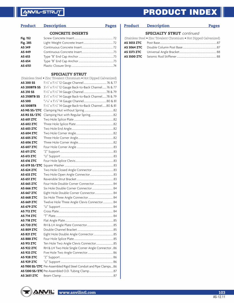
PRODUCT INDEX
www.anvilintl.com 103
Product Description Pages
CONCRETE INSERTSFig. 152 Screw Concrete Insert ............................................................ 72Fig. 285 Light Weight Concrete Insert ............................................. 72AS 349 Continuous Concrete Insert ................................................ 72AS 449 Continuous Concrete Insert .................................................73AS 653 Type “B” End Cap Anchor ......................................................73AS 654 Type “B” End Cap Anchor ......................................................73AS 6151 Plastic Closure Strip .................................................................74
SPECIALTY STRUT
AS 200 SS 15/8" x 15/8" 12 Gauge Channel ................................... 76 & 77 AS 200BTB SS 31/4" x 15/8" 12 Gauge Back-to-Back Channel ...... 76 & 77 AS 210 SS 15/8" x 15/8" 14 Gauge Channel ...................................78 & 79AS 210BTB SS 31/4" x 15/8" 14 Gauge Back-to-Back Channel ......78 & 79AS 500 13/16" x 15/8" 14 Gauge Channel ...................................80 & 81AS 500BTB 15/8" x 15/8" 14 Gauge Back-to-Back Channel ......80 & 81 AS NS SS/ZTC Clamping Nut without Spring .............................................82 AS RS SS/ZTC Clamping Nut with Regular Spring....................................82 AS 601 ZTC Two Hole Splice Plate .............................................................82 AS 602 ZTC Three Hole Splice Plate ..........................................................82 AS 603 ZTC Two Hole End Angle.................................................................82 AS 604 ZTC Two Hole Corner Angle ..........................................................82 AS 605 ZTC Three Hole Corner Angle .......................................................82 AS 606 ZTC Three Hole Corner Angle .......................................................82 AS 607 ZTC Four Hole Corner Angle .........................................................83 AS 611 ZTC “Z” Support ...................................................................................83 AS 613 ZTC “U” Support ..................................................................................83 AS 616 ZTC Four Hole Splice Clevis ...........................................................83 AS 619 SS/ZTC Square Washer ............................................................................83 AS 624 ZTC Two Hole Closed Angle Connector .................................83 AS 633 ZTC Two Hole Open Angle Connector ....................................83 AS 651 ZTC Reversible Strut Bracket .........................................................83 AS 665 ZTC Four Hole Double Corner Connector ............................. 84 AS 666 ZTC Six Hole Double Corner Connector ................................ 84 AS 667 ZTC Eight Hole Double Corner Connector............................ 84 AS 668 ZTC Six Hole Three Angle Connector ...................................... 84 AS 669 ZTC Twelve Hole Three Angle Clevis Connector ............... 84 AS 679 ZTC “U” Support ................................................................................. 84 AS 712 ZTC Cross Plate.................................................................................... 84 AS 714 ZTC “T” Plate ......................................................................................... 84AS 718 ZTC Flat Angle Plate ...........................................................................85 AS 720 ZTC RH & LH Angle Plate Connector .........................................85 AS 809 ZTC Double Channel Bracket ........................................................85 AS 821 ZTC Eight Hole Double Angle Connector ...............................85 AS 888 ZTC Four Hole Splice Plate .............................................................85AS 913 ZTC Ten Hole Two Angle Clevis Connector ...........................85 AS 922 ZTC RH & LH Two Hole Single Corner Angle Connector ...86 AS 923 ZTC Five Hole Two Angle Connector ....................................... 86 AS 928 ZTC “Z” Support .................................................................................. 86 AS 929 ZTC “U” Support ................................................................................. 86AS 1100 SS/ZTC Pre-Assembled Rigid Steel Conduit and Pipe Clamps .....86AS 1200 SS/ZTC Pre-Assembled O.D. Tubing Clamp .....................................87 AS 2651 ZTC Beam Clamp .................................................................................87
Product Description Pages
SPECIALTY STRUT continued
AS 3033 ZTC Post Base ........................................................................................87 AS 3064 ZTC Double Column Post Base .....................................................87 AS 3373 ZTC Universal Angle Bracket ......................................................... 88 AS 3500 ZTC Seismic Rod Stiffener ............................................................. 88
AS-12.11

www.anvilintl.com104
PIPE HANGER PICTORIAL INDEX
PIPE HANGERSCopper Tubing Hangers
Fig. CT-69Adjustable Swivel Ring
Size Range: 1/2" - 4"
Fig. CT-65Light Duty Adjustable Clevis
Size Range: 1/2" - 4"
Fig. CT-138RExtensions Split Tubing Clamp
Size Range: 1/2" - 2"
Fig. CT-121Copper Tubing Riser Clamp
Size Range: 1/2" - 4"
Fig. CT-128RRod Threaded Ceiling Flange
Sizes: 3/8" - 1/2"
Fig. CT-255Copper Tubing
Alignment GuideSize Range: 1" - 4"
Fig. 67Pipe or Conduit Hanger
Size Range: 1/2" - 6"
Fig. 65Light Duty Adjustable Clevis
Size Range: 3/8" - 4"
Fig. 260Adjustable Clevis Hanger
Size Range: 1/2" - 30"
Steel Pipe Clamps
Fig. 261Extension Pipe or
Riser ClampSize Range: 3/4" - 24"
Fig. 40Riser Clamp Standard
Size Range: 2" - 24"
Fig. 103Offset Pipe ClampSize Range: 3/4" - 8"
Fig. 100Extended Pipe Clamp
Size Range: 1/2" - 8"
Fig. 212Medium Pipe Clamp
Size Range: 1/2" - 30"
Fig. 212FPEarthquake Bracing Clamp
Size Range: 21/2" - 12"
Fig. 216Heavy Pipe ClampSize Range: 3" - 42"
Fig. 295Double Bolt Pipe Clamp
Size Range: 3/4" - 36"
Fig. 295AAlloy Double Bolt Pipe Clamp
Size Range: 11/2" - 24"
Fig. 295HHeavy Duty Double Bolt
Pipe ClampSize Range: 6" - 36"
Fig. 224Alloy Steel Pipe Clamp
Size Range: 4" - 16"
Fig. 246Heavy Duty Alloy Steel
Pipe ClampSize Range: 10" - 24"
Clevis
Fig. 260 ISSClevis Hanger with
Insulation Saddle SystemSize Range: 2" - 16"
Fig. 300Adjustable Clevis for
Insulated LinesSize Range: 3/4" - 12"
Fig. 590Adjustable Clevis forDuctile or Cast Iron
Size Range: 3" - 24"
CPVC Pipe Hangers
Fig. 185One Hole Pipe Strap
Size Range: 3/4" - 2"
Fig. 186Two Hole Pipe Strap
Size Range: 3/4" - 2"
Fig. 188Two Hole Stand Off Strap
Size Range: 3/4" - 2"
Fig. 187Two Hole 90˚ Side
Mount StrapSize Range: 3/4" - 2"
Fig. 67FCopper Tube
Felt Lined HangerSize Range: 1/2" - 6"
Fig. 69FCopper Tube
Felt Lined HangerSize Range: 1/2" - 6"
AS-12.11

www.anvilintl.com 105
PIPE HANGER PICTORIAL INDEX
PIPE HANGERS (Continued)
Beam Clamps
Fig. 86 & 88C-Clamp with Set
Screw and Lock NutSize Range: 3/8" - 3/4"
Fig. 95C-Clamp with Lock Nut
Sizes: 3/8" and 1/2"
Fig. 89Retaining Clip
Size Range: 3/8" - 1/2"
Fig. 89XRetaining Clip
Size Range: 3/8" - 3/4"
Fig. 92Universal C-Type Clamp
Standard ThroatSizes: 3/8" and 1/2"
Fig. 93Universal C-Type Clamp
Wide ThroatSizes: 3/8" and 1/2"
Fig. 94Wide Throat Top Beam
C-ClampSizes: 5/8" and 3/4"
Fig. 227Top Beam Clamp
Fig. 217Adjustable SideBeam Clamp
Size Range: 3" - 75/8"
Fig. 14Adjustable SideBeam ClampSizes: 3/8" - 5/8"
Fig. 218Malleable Beam Clamp without Extension Piece
Fig. 228Universal Forged Steel
Beam Clamp
Fig. 292 & 292LUniversal Forged Steel
Beam Clamp with Weldless Eye Nut
Ceiling Plates
Fig. 395Cast Iron Ceiling Plate
Size Range: 1/2" - 8"
Fig. 127Plastic Ceiling Plate
Sizes: 3/8" and 1/2"
Fig. 128RRod Threaded, Ceiling Flange
Sizes: 3/8" and 1/2"
Fig. 153Pipe Hanger Flange
Size Range: 3/8" - 3/4"
Brackets
Fig. 202Iron Side Beam
BracketSize Range:
3/8" - 5/8"
Fig. 206Steel Side Beam
BracketSize Range:
3/8" - 5/8"
Fig. 207Threaded Steel
Side Beam Bracket
Sizes: 3/8" and 1/2"
Fig. 194Light WeldedSteel Bracket
Fig. 195Medium Welded
Steel Bracket
Fig. 199Heavy WeldedSteel Bracket
Fig. 133Standard Duty Beam
ClampSize Range: 4" - 12"
Fig. 134Heavy Duty Beam
ClampSize Range: 4" - 12"
Socket Clamps
Fig. 595 & Fig. 594Socket Clamp
for Ductile Iron or Cast Iron Pipe& Socket Clamp WasherSize Range: 4" - 24" pipe
Fig. 600 & Fig. 599Socket Clamp
for Ductile Iron or Cast Iron Pipe& Socket Clamp WasherSize Range: 3" - 24" pipe
Fig. 189Straight Eye
SocketSize: 3/8"
Fig. 190Off-Set Eye
SocketSize: 3/8"
Fig. 46Universal Trapeze Assembly
Fig. 45Channel Assembly
Fig. 50Equal Leg Angle for Trapeze
Assembly
Trapeze
U-Bolts
Fig. 137 & 137SStandard U-Bolt
Size Range: 1/2" - 36"
Fig. 137CPlastic Coated U-Bolt
Size Range: 1/2" - 8"
Fig. 120Light Weight U-Bolt
Size Range: 1/2" - 10"
AS-12.11

www.anvilintl.com106
PIPE HANGER PICTORIAL INDEX
PIPE HANGERS (Continued)
AS-12.11
Concrete Inserts & Attachments
Fig. 152Screw Concrete Insert
Size Range: 3/8" - 7/8"
Fig. 282Universal
Concrete InsertSize Range: 3/8" - 7/8"
Fig. 281Wedge Type
Concrete InsertSize Range: 1/4" - 7/8"
Fig. 286Iron Cross
Size Range: 3/4" - 11/2"
Fig. 284Metal Deck HangerSize Range: 3/8" - 3/4"
Fig. 285Light Weight Concrete
InsertSize Range: 1/4" - 5/8"
Fig. 52Concrete Rod
Attachment PlateSize Range: 3/8" - 11/4"
Fig. 47Concrete Single Lug
PlateSize Range: 1/2" - 2"
Fig. 49Concrete Clevis Plate
Size Range: 3/8" - 13/4"
Hanger Rods & Accessories
Fig. 142Coach Screw Rods
Machine Threaded on Opposite End
Size Range: 3/8" - 1/2"
Fig. 146Continuous ThreadSize Range: 1/4" - 11/2"
Stocked in six, ten & twelve foot lengths. Other even foot lengths
can be furnished to order.
Fig. 140 & 253Machine Threaded Rods Threaded on Both Ends
Size Range: 3/8" - 5"
Fig. 248Eye Rod Not Welded
Size Range: 3/8" - 21/2"
Fig. 278Eye Rod Welded
Size Range: 3/8" - 21/2"
Fig. 248XLinked Eye Rods
Size Range: 3/8" - 21/2"
Fig. 278XLinked Eye Rods Welded
Size Range: 3/8" - 21/2"
Fig. 148Rod with Eye EndSize Range: 23/4" - 5"
Fig. 135 & Fig. 135EStraight Rod Coupling
Size Range: 1/4" - 1"
Fig. 136 & Fig. 136RStraight Rod Coupling
Size Range: 1/4" - 1"
Fig. 114Turnbuckle Adjuster
Size Range: 1/4" - 3/4"
Fig. 110RSocket, Rod Threaded
Size Range: 1/4" - 7/8"
Fig. 157Extension PieceSize Range: 3/8" - 7/8"
Fig. 299Forged Steel Clevis
Size Range: 3/8" - 4"
Fig. 233Turnbuckle
Size Range: 11/4" - 5"
Fig. 230Turnbuckle
Size Range: 3/8" - 21/2"
Fig. 290Weldless Eye NutSize Range: 3/8" - 21/2"
Fig. 291Clevis Pin with Cotters
Size Range: 1/2" - 4"
Pipe Rings
Fig. 108Split Pipe Ring
Size Range: 3/8" - 8"
Fig. 138RExtension Split Pipe Clamp
Size Range: 3/8" - 3"
Fig. 104Adjustable Swivel Ring, Split Ring Type
Size Range: 3/4" - 8"
Fig. 69Adjustable Swivel Ring
Size Range: 1/2" - 8"
Pipe Supports
Fig. 62Type A, B & CPipe Stanchion
Size Range: 2" - 18"
Fig. 63Type A, B & CPipe Stanchion
Size Range: 21/2" - 42"
Fig. 192Adjustable Pipe Saddle
Size Range: 2" - 12"
Fig. 191Adjustable Pipe
Saddle with U-BoltSize Range: 2" - 12"
Fig. 264Adjustable PipeSaddle Support
Size Range: 21/2" - 36"
Fig. 265Adjustable Pipe Saddle
Support with U-BoltSize Range: 4" - 36"
Fig. 258Pipe Stanchion Saddle
Size Range: 4" - 36"
Fig. 259Pipe Saddle Support
with U-BoltSize Range: 4" - 36"
Fig. 136:Fig. 136R:

www.anvilintl.com 107
PIPE HANGER PICTORIAL INDEX
PIPE HANGERS (Continued)
AS-12.11
Straps
Fig. 126One-Hole ClampSize Range: 3/8" - 4"
Fig. 262Strap Short
Size Range: 1/2" - 4"
Fig. 243Pipe Strap
Size Range: 1/2" - 6" pipe
Fig. 244Pipe Strap
Size Range: 1/2" - 6" pipe
Pipe Rolls
Fig. 177Adjustable Pipe
Roll SupportSize Range: 1" - 30"
Fig. 171Single Pipe RollSize Range: 1" - 30"
Fig. 178Spring Cushion Hanger
Fig. 181Adjustable Steel Yoke Pipe Roll
Size Range: 21/2" - 24"
Fig. 175Roller Chair
Size Range: 2" - 30" pipe
Fig. 277Pipe Roll & Base Plate
Size Range: 2" - 24"
Fig. 271Pipe Roll StandSize Range: 2" - 42"
Fig. 274, 274P & 275Adjustable Pipe
Roll StandSize Range: 2" - 42"
Pipe Guides & Slides
Fig. 255Pipe Alignment Guide
Size Range: 1" - 24" pipe and insulation thickness of 1" thru 4"
(Also available in copper tube sizes)
Fig. 256Pipe Alignment Guide
Size Range: 1" - 24" pipe and insulation thickness of 1" thru 4"
Fig. 257 & 257AStructural Tee
Slide AssemblySize Range: All Sizes within
Maximum Load Rating
Fig. 436 & 436AFabricated TeeSlide Assembly
Size Range: All Sizes within Maximum Load Rating
Fig. 439 & 439AStructural "H"
Slide AssemblySize Range: 6" - 36"
Fig. 432Special Clamp
Size Range: 2" - 24"
Fig. 212Medium Pipe Clamp
Size Range: 2" - 30"
Fig. 167Insulation Protection Shield
Size Range: 1/2" thru 24" pipe with up to 2" thick insulation.
Fig. 168Rib-Lok Shield
Size Range: 1/2" thru 8" pipe or copper tube with up to 2" thick insulation.
Fig. 160 to 166APipe Covering Protection Saddle
Size Range: 3/4" thru 36"
Pipe Shields & Saddles
Structural Attachments
Fig. 55 & Fig. 55LStructural Welding Lug
Size Range:Fig. 55: 1/2" - 33/4"Fig. 55L: 1/2" - 2"
Fig. 54Two Hole Welding Beam Lug
Size Range: 1/2" - 21/4"
Fig. 60Steel Washer PlateSize Range: 3/8" - 33/4"
Fig. 66Welded Beam Attachment
Size Range: 3/8" - 31/2"
Fig. 112 & 113Brace Fitting Compete
Sizes: 1" and 11/4"
Sway Strut Assembly
Fig. 211, C-211, 640, C-640Sway Strut Assembly
Fig. 222 & C-222Mini-Sway Strut Assembly

www.anvilintl.com108
PIPE HANGER PICTORIAL INDEX
Spring Hangers
Fig. 82 & C-82Short Spring
Fig. B-268 & C-268Standard Spring
Fig. 98 & C-98Double SpringConstant Supports
Model R 80-VVertical Constant Support
Model R 81-HHorizontal Constant Support
Size Range: Anvil Model R constant support hangers are made in two basic designs, 80-V & 81-H constant supports are made in nine different frame sizes & 110 spring sizes to accomodate travels from 11/2" to 20" & loads from 27 lbs to 87,500 lbs.
Horizontal Traveler & Sway Brace
Fig. 170Horizontal Traveler
Size Range: Available in Four Sizes to Take Loads to 20,700
(LBS). All sizes provide for 12" of Horizontal Travel.
Fig. 296, 297, 298, 301, 302, 303Sway Brace
Size Range: Pre Loads from 50 to 1,800 Pounds &
maximum forces from 200 to 7,200 Pounds.
Snubbers
Fig. 3306 & 3307Hydraulic Shock & Sway Suppressor (Snubber)
Size Range: Seven standard sizes with load ratings from 350 to
50,000 (LBS).
Fig. 312Tapered Pin
Size Range: 3/8" - 21/2"
Fig. 200 & C-200 / Fig. 201 & C-201Hydraulic Shock & Sway Suppresor (Snubber)
Size Range: Nine standard sizes with cylinder bores of 11/2" to 8" with normal load ratings from 3,000 (LBS) to 128,000 (LBS). All are
available with 5", 10", 15" or 20" strokes except the 11/2" size which is offered with 5" and 10" strokes only. Snubbers are available with
integral or remote reservoirs.
Triple Spring,Triple Spring-CR
Quadruple Spring,Quadruple Spring-CR
PIPE HANGERS (Continued)
SWAY BRACE - SEISMICPipe Brace Clamps
Fig. 770Q Brace Clamp
Size Range:1" - 6" Service Pipe
Fig. 776Brace Clamp
Size Range:21/2" - 8" Service Pipe
Fig. 775Lateral/Longitudinal
Brace ClampSize Range:
21/2" - 8" Service Pipe
Structural Attachments
Fig. 778Bar Joist and Beam Attachment (WF)
Size Range: Flange Thickness 1/8" - 3/4"
Fig. 772Adjustable Steel Beam Attachment
Size Range: Flange Widths 4" - 15"
Fig. 779Multi-Connector Adapater
Size Range: 1" - 8" Service Pipe
Restraints
Fig. 773Surge Restrainer
Size Range: 3/4" - 2" Swivel Ring Hanger
Fig. 777Swivel Joint Connector - Rod Tap
Size Range: 3/8" Rod Diameter
AS-12.11
Sway Brace Attachment
Fig. 771Sway Brace Swivel AttachmentSize Range: 1" and 11/4" Brace Pipe

www.anvilintl.com 109
NOTES

www.anvilintl.com110
NOTES

www.anvilintl.com 111
NOTES

www.anvilintl.com112
NOTES

PIPE HANGERS & SUPPORT CATALOG
ORDER DOCUMENT #165
GRUVLOK MECHANICAL
PIPING PRODUCTS CATALOG
ORDER DOCUMENT #040
PIPE FITTINGS CATALOG ORDER DOCUMENT #010
ANVIL-STRUT METAL FRAMING
PRODUCT & ENGINEERING CATALOG
ORDER DOCUMENT #125
PIPE FITTERS HANDBOOK
ORDER DOCUMENT #030

B U I L D I N G C O N N E C T I O N S T H A T L A S T
We built our reputation from the ground up.
Anvil’s history stretches back to the mid 1800s,when a company named Grinnell® began providingits customers with the finest quality pipe products.Since 2000, those quality products and services—and the people who provide them—have beenknown as Anvil® International. Anvil® customers receive the quality and integrity that have been building strong connections in both productsand business relationships for over 150 years.
TRUSTEDFOR 150 YEARS
Focused Product Line:
Anvil® Malleable and CastIron Fittings
Anvil® Hangers, Supportsand Struts
Beck Welded Pipe Nipples
Anvil® Seamless PipeNipples
Anvil® Steel Pipe Couplingsand Small Steel Fittings
Merit® Tee-Lets and DropNipples
Gruvlok® Couplings,Fittings and Valves
SPFTM Malleable and Castand Ductile Iron Fittings
SPF TM Grooved Fittings and O’Lets
J.B. Smith Swage Nipplesand Bull Plugs
Catawissa® Wing Unionsand Check Valves
Today Anvil® International is the largest and most complete fitting and hanger manufacturer in the world.
2004 Anvil® International acquires Star Pipe Products, Building and Construction Divisions (SPF) and forms AnvilStarTM Fire Products Division.
2001 Anvil® International acquires Merit® Manufacturingand Beck Manufacturing.
2000 The industry’s trusted manufacturer of pipefittings, hangers and grooved fittingsis renamed Anvil® International, Inc.
1999 Tyco sells the distribution and manufacturingoperations known up to this point as ”Grinnell Supply Sales”, but keeps the Grinnell® trademark.
1994 J.B. Smith™ and Catawissa™ join the Grinnell Supply Sales and Manufacturing division.
1850 Providence Steam & Gas Pipe Co. is formed, andFrederick Grinnell purchases a controlling interest.
1909 Frederick Grinnell opens a foundry in Cranston, RI.Companies express interest in buying its pipingproducts, laying the groundwork for what wouldbecome the Grinnell Supply Sales Division. It would be these manufacturing and sales operations thateventually become Anvil® International.
1919 General Fire Extinguisher Co. becomes Grinnell Co.
1960 Gruvlok® line of grooved fittings is introduced.
1969 Grinnell Co. acquired by International Telephone and Telegraph. Two years later, ITT divests the FireProtection Division, but keeps the manufacturingand sales divisions that will become known asAnvil® International.
Grinnell® is a registered trademark of Grinnell Corporation, a Tyco International Ltd. company.
ANVIL BRANDS:

B R A N D S O F A N V I L I N T E R N AT I O N A L
Anvil® product lines include malleable and cast iron fittings, unions and flanges; seamless steel pipe nipples; steel pipe couplings; universal anvilets; forged steel fittings and unions; pipe hangers and supports; threaded rod; and engineered hangers.
The Gruvlok® product line consists of couplings for grooved and plain-end fittings, butterfly valves and check valves; flanges; pump protection components; pipe grooving tools; as well as copper and stainless steel system components.
Anvil-Strut™ products include a complete line of channel in stock lengths of 10 and 20 feet, with custom lengths available upon request. A variety of fittings and accessories are also offered. All products can be ordered in an assortment of finishes and material choices including SupR-Green™, Zinc Trivalent Chromium, pre-galvanized, hot-dipped galvanized, electro-galvanized, aluminum, plain, and stainless steel.
JB Smith™ is the leading manufacturer of oil country tubular fittings, swages and bull plugs – all meeting API specifications. Offering tubing nipples, casing nipples as well as a full line of traditional line pipe and oil country threads in every schedule, JB Smith is the resource for all your oilfield needs.
Catawissa™ NACE and API approved wing unions for Standard Service are offered in non-pressure seal ends as well as threaded and butt weld, and are interchangeable with most leading union manufacturers. Fully traceable and available with complete mill certifications, Catawissa’s oilfield wing union product line includes the standard ball-and-cone design plus our unique Figure 300 Flat Face design, where space and pipe line separation are a consideration.
The SPF/Anvil™ product line includes a variety of internationally sourced products such as grooved couplings, fittings and flanges, cast iron, malleable iron and ductile iron threaded fittings, steel pipe nipples, as well as o’lets.
The Merit® product line includes a variety of tee-lets, drop nipples, and steel welding flanges for fire protection applications. Most Merit products are UL/ULC Listed, FM Approved, and rated from 175 to 300 psi.
Steel pipe nipples and steel pipe couplings are manufactured in accordance with the ASTM A733 Standard Specification for Welded and Seamless Carbon Steel and Stainless Steel Pipe Nipples. Steel pipe couplings are manufactured in accordance with the ASTM A865 Standard Specification for Threaded Couplings, Steel, Black or Zinc-Coated (Galvanized) Welded or Seamless, for Use in Steel Pipe Joints. API couplings are manufactured in accordance with the API Specification for line pipe.
Canvil® manufactures low pressure hexagon reducer bushings, as well as plugs and hex caps up to 1” in diameter in various finishes including Oil Treat, Phosphate and Electro Galvanized. In addition, Canvil manufactures A105 hex or round material in class 3000 and 6000 pound, forged steel couplings and bar stock products offered as either as normalized (A105N) or non-normalized (A105) that are fully traceable for mechanicals and chemistry through our MTR program.
Anvil EPS-Engineered Pipe Supports are products used to support piping systems under thermal, seismic, and other dynamic loading conditions. The product line encompasses variable spring hangers, constant supports, sway struts and snubbers as well as standard and special design clamps. Anvil EPS brings the highest quality products and innovative engineering solutions to common and uncommon piping system problems.

Corporate Offices110 Corporate Drive, Suite 10 P.O. Box 3180 Portsmouth, NH 03801-3180
Tel: 603-422-8000 Fax: 603-422-8033
E-mail: [email protected]
U.S. REGIONAL SERVICE CENTERS
Anvil International CanadaCustomer Service Center390 Second AvenueP.O. Box 40Simcoe, Ontario N3Y 4K9
Tel: 519-426-4551Fax: 519-426-5509
CANADA SERVICE CENTER
www.anvilintl.com
B U I L D I N G C O N N E C T I O N S T H A T L A S T
Northern RegionRegional Distribution & Customer Service Center
750 Central Avenue University Park, IL 60484
Tel: 708-885-3000 Fax: 708-534-5441 Toll Free: 1-800-301-2701
Southern RegionRegional Distribution & Customer Service Center1401 Valley View Lane, Suite 150Irving, TX 75061
Tel: 972-871-1206 Fax: 972-641-8946 Toll Free: 1-800-451-4414
INTERNATIONAL SALES
Mexico, Puerto Rico andLatin AmericaInternational Customer Service
Tel: +1-708-885-3000 Fax: +1-708-534-5441
Europe and Middle East RegionRick van [email protected]
Tel: +31-53-5725570 Fax: +31-53-5725579
#125/Printed in USA/© Copyright 2011Revision Date: 12.1.11