METAL DETECTOR METAL SHARK BD Original … · METAL DETECTOR METAL SHARK ® BD Original Manual /...
86
METAL DETECTOR METAL SHARK ® BD Original Manual / Documentation (English) Software Version 3.94o (English) and higher Print date: 2008-12-08
Transcript of METAL DETECTOR METAL SHARK BD Original … · METAL DETECTOR METAL SHARK ® BD Original Manual /...
METAL DETECTOR
METAL SHARK ® BD
Original Manual / Documentation (English)
Software Version 3.94o (English) and higher
Print date: 2008-12-08
METAL SHARK® BD
Table of Contents
1. General Information............................ .............................................................................5
1.1. How to use this Manual / Documentation...................................................................5
2. Declarations................................... ...................................................................................6
2.1. CE - Declaration of Conformity...................................................................................62.2. Manufacturer’s Declaration........................................................................................7
3. Area of Application and Qualification.......... ...................................................................8
3.1. Normal Use................................................................................................................83.2. Misuse........................................................................................................................83.3. Owner's Obligation to Exercise Due Care..................................................................83.4. Requirements for Operating Staff...............................................................................93.5. Requirements for Service and Maintenance Staff......................................................9
4. General Safety Instructions.................... .......................................................................10
4.1. General Safety Instructions......................................................................................104.2. Safety Instructions for the Metal Detector.................................................................11
4.2.1. Installation Instructions..................................................................................114.2.2. Connecting Instructions................................................................................124.2.3. Operating Instructions...................................................................................124.2.4. Protection Against Interference.....................................................................12
5. Technical Description.......................... ..........................................................................13
5.1. Metal Detector METAL SHARK® BD........................................................................135.2. Method of Operation.................................................................................................145.3. Operating Limits.......................................................................................................14
6. Transport...................................... ...................................................................................15
6.1. Safety Instructions for Transport and Installation......................................................156.2. Transporting.............................................................................................................16
7. Installation Instructions...................... ...........................................................................17
7.1. Metal-Free Zone.......................................................................................................177.2. Vibration...................................................................................................................177.3. Feed of Belt Through Sensor...................................................................................187.4. Mounting on Conveyor / Frame................................................................................187.5. Keep Conveyor Belt Clean.......................................................................................187.6. Installation of Sensor Head......................................................................................187.7. Control Unit for Wall-Mounting..................................................................................19
8. Operating Instructions......................... ..........................................................................20
8.1. Keyboard..................................................................................................................208.2. Menu Structure.........................................................................................................218.3. Product Effect Compensation: Background Information...........................................228.4. Starting Up...............................................................................................................23
8.4.1. Power On......................................................................................................238.4.2. Expert Mode.................................................................................................248.4.3. Set Product Speed........................................................................................25
Seite 2 Software Version 3.94o and higher
METAL SHARK® BD
8.4.4. Set Product 000............................................................................................268.4.5. Teach Product 001 to 120.............................................................................278.4.6. Optimize Product Effect Compensation........................................................298.4.7. Check Metal Sensitivity.................................................................................308.4.8. Enter Product Name.....................................................................................328.4.9. Password Feature.........................................................................................338.4.10. Set Date and Time......................................................................................368.4.11. Displaying / Printing Reports.......................................................................37
9. The Metal Detector’s Functions in Detail....... ..............................................................38
9.1. Main Menu...............................................................................................................389.1.1. Main Screen: Product and Signal..................................................................389.1.2. Teach Product – Teach Product Effect..........................................................389.1.3. Product Tolerance.........................................................................................399.1.4. Metal Sense mV...........................................................................................399.1.5. Info Next PV Test..........................................................................................399.1.6. Open Menu...................................................................................................409.1.7. Password......................................................................................................40
9.2. Report Menu............................................................................................................409.2.1. Metal Counter...............................................................................................409.2.2. Info Last Metal..............................................................................................419.2.3. Info Product..................................................................................................419.2.4. Info Software Version....................................................................................419.2.5. Print..............................................................................................................429.2.6. Interface........................................................................................................429.2.7. BAUD............................................................................................................429.2.8. SHARKNET / Unit #......................................................................................439.2.9. Report to Printer...........................................................................................439.2.10. Report to LCD.............................................................................................449.2.11. Exit Report Menu........................................................................................44
9.3. Product Menu...........................................................................................................459.3.1. Product Name...............................................................................................459.3.2. Product is .....................................................................................................469.3.3. Product X TOL..............................................................................................469.3.4. Product Y TOL..............................................................................................479.3.5. Teach Area....................................................................................................479.3.6. Amplification X%...........................................................................................479.3.7. Amplification Y%...........................................................................................489.3.8. Phase...........................................................................................................489.3.9. Phase Track..................................................................................................489.3.10. Metal Contact..............................................................................................499.3.11. Copy Product..............................................................................................499.3.12. Exit Product Menu.......................................................................................49
9.4. Teach Menu..............................................................................................................509.4.1. Teach Sense mV...........................................................................................509.4.2. Teach min Count...........................................................................................509.4.3. Teach Max Count..........................................................................................519.4.4. Teach Time...................................................................................................519.4.5. STATISTIC sec.............................................................................................519.4.6. Teach enable................................................................................................529.4.7. Teach reject..................................................................................................52
Software Version 3.94o and higher Seite 3
METAL SHARK® BD
9.4.8. Exit Teach Menu...........................................................................................529.5. Validation Menu........................................................................................................53
9.5.1. Reject Confirm..............................................................................................539.5.2. Bin Full..........................................................................................................539.5.3. Low Air..........................................................................................................539.5.4. Performance Validation Menu.......................................................................549.5.5. PVS..............................................................................................................549.5.6. Exit Validation Menu.....................................................................................56
9.6. System Menu...........................................................................................................579.6.1. Speed...........................................................................................................579.6.2. Remote Product............................................................................................579.6.3. Password......................................................................................................589.6.4. Expert Mode.................................................................................................589.6.5. Reject Menu..................................................................................................599.6.6. Date / Time Menu.........................................................................................619.6.7. Autospeed Menu...........................................................................................629.6.8. CIP Menu......................................................................................................639.6.9. In/Out Menu..................................................................................................649.6.10. Exit In/Out Menu.........................................................................................679.6.11. Sensor Menu...............................................................................................69
9.7. Exit Menu.................................................................................................................71
10. Electrical Connections........................ .........................................................................72
10.1. Terminals of Power Supply Board..........................................................................7210.2. Relais K1, K2 - Function.........................................................................................7210.3. Terminals on the Mainboard...................................................................................7310.4. Terminals / Electrical Wiring and Functions............................................................7410.5. Wiring Diagram: Reject = Belt Stop (Conveyor Models).........................................7610.6. Wiring Diagram: Reject = Pneumatic Pusher (Conveyor Models)..........................77
11. Maintenance and Regular Inspections........... ............................................................78
11.1. Maintenance...........................................................................................................7811.2. Regular Inspections................................................................................................7811.3. Notes......................................................................................................................78
12. Conveyor Belt System.......................... .......................................................................79
12.1. Conveyor Belt Maintenance...................................................................................79
13. Error Messages and Trouble Shooting........... ............................................................80
13.1. Error Messages of the Software.............................................................................80
14. Instruction Sheet............................. .............................................................................82
14.1. General Function....................................................................................................8214.2. General Metal Detector Manual..............................................................................83
Parameter List METAL SHARK® / Software 3.94o....... .....................................................84
Seite 4 Software Version 3.94o and higher

METAL SHARK® BD
1. General Information
1.1. How to use this Manual / Documentation
Validity: Metal detector type METAL SHARK® BD
Manufacturer: Cassel Messtechnik GmbH
In der Dehne 10
37127 Dransfeld
Germany
Print date of this manual: December 08
This manual / documentation contains all general information that is necessary for setting up and
running METAL SHARK® Metal Detectors.
Please refer to the annex for further information about your specific METAL SHARK®
metal detector.
This document is directed to operators as well as technical staff with the following tasks:
• Operating metal detector,
• initial operation (only technicians),
• regular inspections and maintenance work,
• safety check before and during the work with the metal detector,
• eliminating errors.
This manual / documentation was compiled in January 2003 according to the guidelines of theEuropean standard EN 292-1/2:1991D, "Safety of machines". It completes the existing nationalregulations for accident prevention that you have to follow when running such machines.
Before the initial operation of the metal detector all persons that are authorised to work on and with themetal detector have to read and understand this manual / documentation. Alternatively the employercan deal with the context of this manual / documentation. Special interest is to be paid to the safetyinstructions.
The manual / documentation must stay with the metal detector. All authorised persons must haveaccess to it at any time. You are not aloud to remove any chapters from this manual / documentation.A missing manual / documentation or missing pages (especially the chapter “Safety instructions“) haveto be replaced immediately.
Note:
Cassel Messtechnik GmbH gives no implicit guarantees regarding standard qualities or suitability for acertain application.
This documentation contains information which is subject to copyright. No part of it may bephotocopied, duplicated, translated or recorded on data media without prior consent from CasselMesstechnik GmbH.
This documentation is not subject to change control by Cassel Messtechnik GmbH. The manufacturerreserves the right to make changes to this documentation. All rights reserved.
Software Version 3.94o and higher Seite 5
METAL SHARK® BD
2. Declarations
2.1. CE - Declaration of Conformity
according to annex II A of the EC Machinery Directi ve (2006/42/EC)
The manufacturer: Cassel Messtechnik GmbHIn der Dehne 1037127 Dransfeld / Germany
certifies herewith that the machine Metal detector type METAL SHARK ® BD
fulfils the safety and health requirements of the EC directives:
EC-Machinery Directive 2006/42/EC
EC-Directive electromagnetic compatibility 2006/95/ EC
Electromagnetic Compatibility 2004/108/EC
EC-Directive „explosion protection“ 94/9/EC (ATEX)
Relevant harmonised European standards:
EN ISO 12100-1 Safety of machinery. Basic concepts, general principles for design. Basic termino-logy, methodology
EN ISO 12100-2 Safety of machinery. Basic concepts, general principles for design. Technical prin-ciples and specifications
DIN EN 60204 - 1 Safety of machinery - Electrical equipment of machines - General requirements
DIN EN 60529 Degrees of protection provided by enclosures (IP code)
DIN EN 60947-7 Low-voltage switchgear and control gear - Part 7-1: Ancillary equipment; Terminalblocks for copper conductors.
DIN EN 61558 Isolating transformers and safety isolating transformers
DIN EN 61000 Electromagnetic compatibility (EMC)
EN 50022 Low voltage switchgear and control gear for industrial use; mounting rails, top hatrails, 35 mm wide, for snap-on mounting of equipment
EN 61000-6-4 Electromagnetic compatibility (EMC). Generic standards. Emission standard forindustrial environments
EN 61000-6-1 Electromagnetic compatibility (EMC). Generic standards. Immunity for residential,commercial and light-industrial environments
Herewith we declare that we followed the relevant safety norms and requirements for technical safety and for explosionprevention for the intended use when constructing and producing this metal detector.
The metal detector is destined for facilities that are protected against explosions by the safety measure “no potential ignitionsource“.
Equipment marking:
• Category II 3D T3
• Equivalent to Zone 22 in EN 1127-1
• Complies with EG directive 94/9/EC (ATEX 95)
Constructional changes which have effects on the te chnical information in this manual and on the inten ded utilisation,and therefore convert the machine considerably, mak e this declaration of conformity invalid!
Dransfeld, 08 December 2008Cord Cassel, Managing Director
Seite 6 Software Version 3.94o and higher
METAL SHARK® BD
2.2. Manufacturer’s DeclarationThe producer: Cassel Messtechnik GmbH
In der Dehne 1037127 Dransfeld, Deutschland
certifies herewith that the machine Metal detector type METAL SHARK ® BD
is in conformity with the provisions of the following EC Directive(s) when installed in accordance with the installation instruc-tions contained in the product documentation:
EC-Machinery Directive 2006/42/EC
EC-Directive electromagnetic compatibility 2006/95/ EC
Electromagnetic Compatibility 2004/108/EC
EC-Directive „explosion protection“ 94/9/EC (ATEX)
Herewith we declare that the described product is intended to be incorporated into machinery and must not be put into serviceuntil the machinery into which it is to be incorporated has been declared in conformity with the provisions of the EU-directives2006/42/EC and explosion protection 94/9/EC.
The equipment complies with:
EN ISO 12100-1 Safety of machinery. Basic concepts, general principles for design. Basic termino-logy, methodology
EN ISO 12100-2 Safety of machinery. Basic concepts, general principles for design. Technical prin-ciples and specifications
DIN EN 60204 - 1 Safety of machinery - Electrical equipment of machines - General requirements
DIN EN 60529 Degrees of protection provided by enclosures (IP code)
DIN EN 60947-7 Low-voltage switchgear and control gear - Part 7-1: Ancillary equipment; Terminalblocks for copper conductors.
DIN EN 61558 Isolating transformers and safety isolating transformers
DIN EN 61000 Electromagnetic compatibility (EMC)
EN 50022 Low voltage switchgear and control gear for industrial use; mounting rails, top hatrails, 35 mm wide, for snap-on mounting of equipment
EN 61000-6-4 Electromagnetic compatibility (EMC). Generic standards. Emission standard forindustrial environments
EN 61000-6-1 Electromagnetic compatibility (EMC). Generic standards. Immunity for residential,commercial and light-industrial environments
Herewith we declare that we followed the relevant safety norms and requirements for technical safety and for explosionprevention for the intended use when constructing and producing this metal detector.
The metal detector is destined for facilities that are protected against explosions by the safety measure “no potential ignitionsource“.
Equipment marking:
• Category II 3D T3
• Equivalent to Zone 22 in EN 1127-1
• Complies with EG directive 94/9/EC (ATEX 95)
Constructional changes which have effects on the te chnical information in this manual and on the inten ded utilisation,and therefore convert the machine considerably, mak e the Manufacturer's Declaration invalid!
Dransfeld, 08 December 2008Cord Cassel, Managing Director
Software Version 3.94o and higher Seite 7

METAL SHARK® BD
3. Area of Application and Qualification
3.1. Normal Use
The Metal Detectors of the METAL SHARK® series are solely designed for detecting foreign metalbodies in non-metal products. Metal can be detected in products that are in a
• solid,
• liquid or
• powder
form.
3.2. Misuse
The METAL SHARK® series is not designed for uses other than those listed in chapter “3.1 NormalUse” otherwise it is regarded as misuse. In particular, we draw attention to the fact that it is not allowed
• to change or remove safety components from the metal detector or the associated peripheralequipment in order to perform measurements other than those indicated in chapter “3.1 NormalUse”,
• to use the machine for a purpose which is not approved,
• to convert the machine without consent from Cassel Messtechnik GmbH in order to use it for adifferent purpose. Please bear in mind that if you convert the metal detector you are consideredthe manufacturer – with all the consequences!
3.3. Owner's Obligation to Exercise Due Care
The METAL SHARK® series has been designed and built taking due consideration of a hazardanalysis and after careful selection of the harmonised standards to be observed, as well as othertechnical specifications. It is therefore state of the art and guarantees maximum safety.
However, in practical operation this safety can only be maintained if all the necessary measures aretaken. As part of his obligation to exercise due care, the owner must take these measures and controltheir implementation.
The owner of the equipment must, in particular, ensure
• that the machine is only subjected to normal use (refer to “3.1 Normal Use”),
• that the machine will only be operated if it is in good working condition and the safety devices arechecked regularly to make sure they are operative,
• that the Operating Instructions are always in a legible state and are available in their entirety at theplace where the machine is used,
• that only adequately qualified and authorised staff operates, services and repairs the machine,
• that before working with the metal detector for the first time, and also thereafter on a regular basis,the staff receives instruction on all the relevant issues regarding safety at work and environmentalprotection and that they are acquainted with the Operating Instructions and particularly the safetyinstructions therein,
• that all the safety signs and warnings attached to the machine are not removed and remainlegible.
Seite 8 Software Version 3.94o and higher

METAL SHARK® BD
3.4. Requirements for Operating Staff
To operate the Metal Detector METAL SHARK® series no special knowledge of measuring technology,mechanical engineering or electrical engineering is necessary. However, the operating staff must be atleast 18 years of age and, before working with the metal detector for the first time, must have receivedtraining from the owner of the machine.
After receiving initial training the operating staff must be in a position to perform the following activitieswithout supervision:
• Putting the metal detector into operation and taking it out of operation.
• Being acquainted with the functions of the metal detector and being able to carry them out.
• Performing regular performance checks and visual inspections on the metal detector.
• Inspecting the safety devices before and during operation.
• Eliminating minor malfunctions for which no occupational training in the field of mechanicalengineering or electrical engineering is required.
3.5. Requirements for Service and Maintenance Staff
To be able to perform maintenance work properly, a period of occupational training in the area ofmechanical engineering or electrical engineering must have been successfully completed. Only trained
maintenance staff is allowed to repair METAL SHARK® Metal Detectors.
For service and maintenance work on the metal detector knowledge of the German or Englishlanguage is absolutely essential.
After initial training the service and maintenance staff must be in a position to perform the followingactivities without supervision:
• Conducting regular performance checks and visual inspections on the metal detector.
• Locating and eliminating malfunctions.
• Inspecting the safety devices on a regular basis.
• Commissioning, maintaining, repairing and turning off the metal detector.
Software Version 3.94o and higher Seite 9

METAL SHARK® BD
4. General Safety Instructions
4.1. General Safety Instructions
Danger!
This Symbol indicates that there is a potential danger for lifeand health.
• Never put the metal detector into operation without the safety devicesprovided by the manufacturer. Only specially trained maintenance staffis allowed to operate the equipment without the safety devices.
• Shut down the machine immediately if the safety devices are notoperating properly or if there are other apparent defects which pose a
danger. Any defects must be eliminated or reported immediately.
• Always observe any warning signs attached to the machine. They help prevent dangeroussituations. The removing of these warning signs is strictly prohibited.
• Never put the metal detector into operation
• if you have not received complete initial training from the owner,
• if you have not fully read the operating instructions or
• if you have not fully understood the operating instructions.
• Not operating the machine correctly may result in severe injury or damage.
• Entering the area of the equipment is strictly prohibited for unauthorised persons. An unauthorisedperson is a person who has not been instructed to work on the metal detector.
• Wear closely fitting working clothes which cannot get caught in rotating parts (e.g. conveyor belt).
• Keep the floor at your place of work clean. Remove oil and obstructions immediately.
• Naked flames and smoking are not allowed.
Seite 10 Software Version 3.94o and higher
METAL SHARK® BD
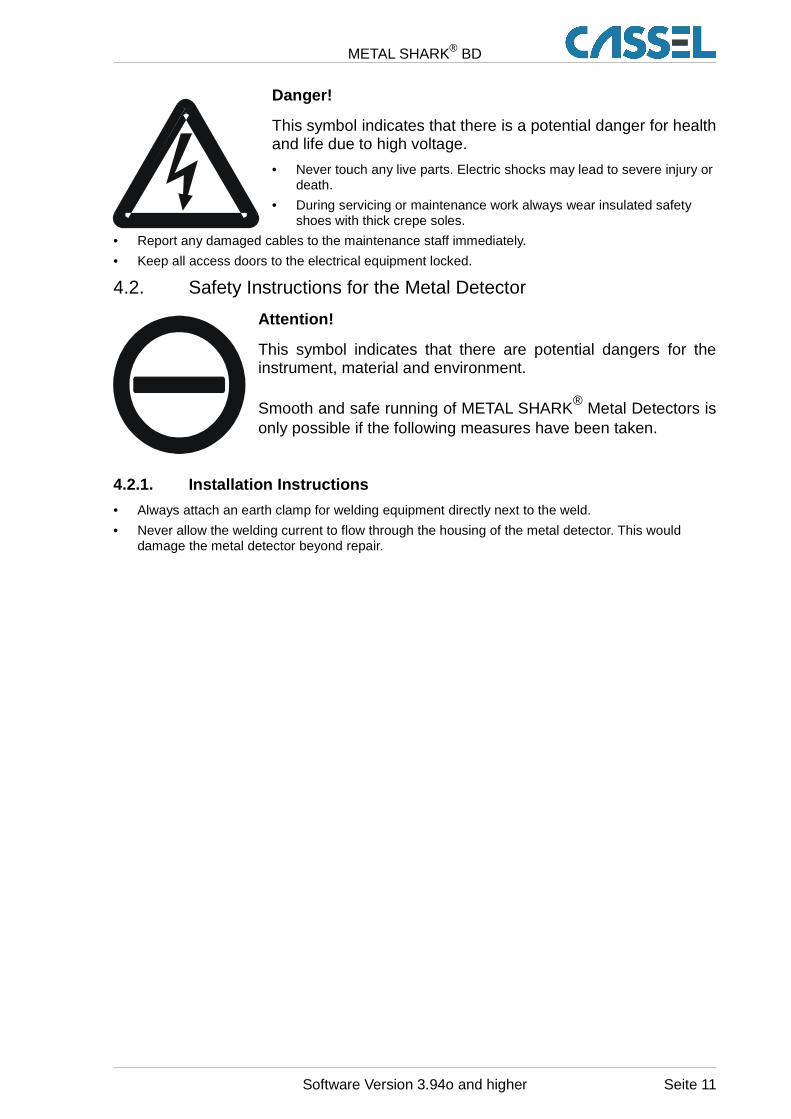
Danger!
This symbol indicates that there is a potential danger for healthand life due to high voltage.
• Never touch any live parts. Electric shocks may lead to severe injury ordeath.
• During servicing or maintenance work always wear insulated safetyshoes with thick crepe soles.
• Report any damaged cables to the maintenance staff immediately.
• Keep all access doors to the electrical equipment locked.
4.2. Safety Instructions for the Metal Detector
Attention!
This symbol indicates that there are potential dangers for theinstrument, material and environment.
Smooth and safe running of METAL SHARK® Metal Detectors isonly possible if the following measures have been taken.
4.2.1. Installation Instructions
• Always attach an earth clamp for welding equipment directly next to the weld.
• Never allow the welding current to flow through the housing of the metal detector. This woulddamage the metal detector beyond repair.
Software Version 3.94o and higher Seite 11
METAL SHARK® BD
4.2.2. Connecting Instructions
• Check to make sure the mains voltage is the same as that required for the equipment.
• Only trained staff is allowed to fit and connect the metal detector.
• Observe general installation regulations for setting up and operating electrical equipment (VDE0100).
• Consequently, never perform any work on the metal detector when it is switched on.
• Take precautions to protect human life and the machine in accordance with the local conditionsand regulations.
• The Metal Detector METAL SHARK® series is designed for permanent, steady-state installation.
• Never connect or disconnect control cables or coaxial cables whilst the metal detector is switchedon.
• Never connect mains cables, control cables or coaxial cables incorrectly.
• Observe the current-carrying capacity of the output contacts.
• Use screened/twisted-wire mains and control cables. Only connect the screening to the earth leadat the metal detector end.
• Never put the mains cable and control cable in the same cable run.
• Make sure the metal detector is properly earthed (neutral earth; avoid earth loops; use theshortest connection to the main earth).
4.2.3. Operating Instructions
To prevent the metal detector from ageing prematurely or being damaged beyond repair, pleaseobserve the following instructions:
• The metal detector should always remain switched on. This will maximise the service life of theelectronic circuitry.
• Only operate the metal detector under suitable conditions (refer to chapters above).
4.2.4. Protection Against Interference
The mains input of the metal detector is protected against interference.
A high level of operational reliability and additional protection against malfunctions is achieved by thefollowing measures:
• Use of mains filters if the mains voltage is affected by the switching-on of heavy-load appliances(compensation systems, welding equipment, HF furnaces, solenoid valves, etc.).
• Providing suppresser circuits for inductance appliances (solenoid valves, contactors,electromagnets) using RC elements (Resistor/Capacitor elements) in order to absorb the energybeing released by switching off.
Seite 12 Software Version 3.94o and higher
METAL SHARK® BD
5. Technical DescriptionThis section tells you about the design of your metal detector and how it operates. We are sure thatthe information will help you to use the metal detector to your full advantage.
5.1. Metal Detector METAL SHARK® BD
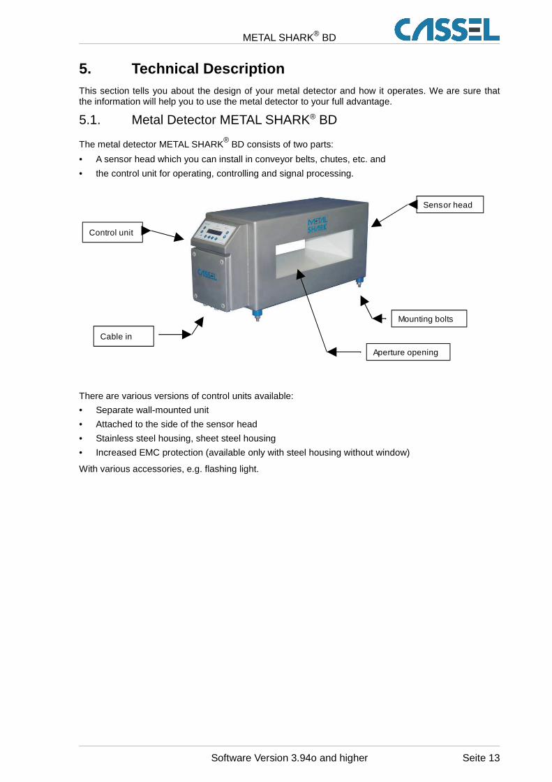
The metal detector METAL SHARK® BD consists of two parts:
• A sensor head which you can install in conveyor belts, chutes, etc. and
• the control unit for operating, controlling and signal processing.
There are various versions of control units available:
• Separate wall-mounted unit
• Attached to the side of the sensor head
• Stainless steel housing, sheet steel housing
• Increased EMC protection (available only with steel housing without window)
With various accessories, e.g. flashing light.
Software Version 3.94o and higher Seite 13
Control unit
Sensor head
Aperture opening
Mounting bolts
Cable in

METAL SHARK® BD
5.2. Method of Operation
METAL SHARK® Metal Detectors operate on the principle of inductance measurement, which is brieflydescribed below.
The sensor has two coils:
• the transmitter coil and
• the receiver coil.
The pair of coils must be balanced before measuring. They are balanced automatically after switchingon the metal detector. This is called "adjustment".
In the transmitter coil a generator is used to create a flow of electric current. This creates anelectromagnetic alternating field (magnetic field) in the sensor.
If a particle of metal now passes through the metal detector — and hence through the magnetic field— the magnetic field of the transmitter coil changes. As a result of the change in the magnetic field anelectric current is created in the receiver coil. This process is termed "electromagnetic induction".
The amount of current generated (induced) is directly proportional to the magnetic and electricalproperties of the metal piece:
• Large metal piece induce a higher current than small metal particles
• Magnetic metals (e.g. steel) induce a higher current than non-magnetic metals (e.g. aluminium)
The current thus induced is measured and then processed and analysed by the electronic circuitry.
Since this method of measurement responds to
• electrical conductivity and
• magnetism
all types of metal are detected. However, magnetic metals are detected more reliably than non-magnetic ones. This way of measuring also makes it possible to detect metal particles inside theproduct or in non-metal packaging.
The examined products are not harmed or changed in any way.
5.3. Operating Limits
Not only metals but also many other materials and raw materials are more or less electricallyconductive. The reasons for this can, for example, be that the products consist of
• salts,
• sugar,
• minerals,
• moisture or
• carbons.
This means that a current is constantly being induced in the receiver coil although there are no metalparticles in the material being examined. This effect is termed "product effect" or "material effect".
The product effect has a characteristic value for each material. Since this value is constant within acertain bandwidth, it can be taken into account by the metal detector and compensated.
The level of sensitivity which can be achieved in practice often depends on:
• How well the metal detector compensates the product effect.
• How carefully the metal detector has been installed (e.g. strong vibrations, moving metal directlynext to the sensor, electromagnetic interferences etc.).
Seite 14 Software Version 3.94o and higher

METAL SHARK® BD
6. Transport
6.1. Safety Instructions for Transport and Installation
To prevent damage to the machine and hazardous inju ries whentransporting and installing the machine it is absol utely essentialthat you keep in mind the following instructions:• Only qualified personnel considering safety instructions is allowed to transport
and install the metal detector.
• The machine may only be lifted using the frame provided.
• To transport the machine only the hoisting and sling gear specified here may be used.
• When selecting suitable hoisting equipment always take the following weights into account:depending on size and type, the metal detector can weigh up to 1,000 kg.
• A third person must secure the transport route.
• The transport routes must be cordoned off and secured so that no unauthorised persons mayenter the danger zone.
• Sharp edges may cause injuries.
• Suspended loads may drop. There is a risk of fatal injury – never stay under suspended loads.
• Live ends of electric cables and components may cause injuries due to electric shock.
• Parts lying unsecured on top of one another may slip and drop.
• During welding there is a risk of fire.
• Cables which have not been laid properly (e.g. radius of curvature too small) may causesmouldering fires and cable fires
• Also read chapter “4 General Safety Instructions”.
Software Version 3.94o and higher Seite 15
METAL SHARK® BD
6.2. Transporting
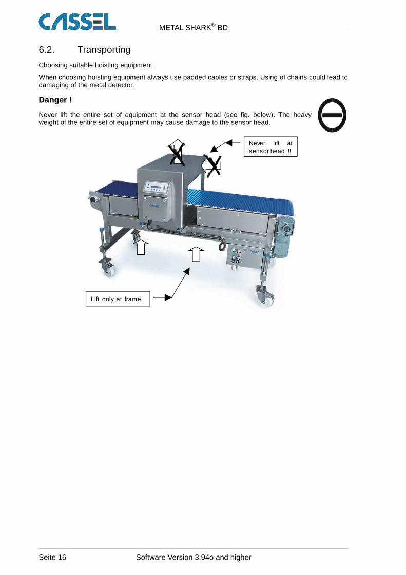
Choosing suitable hoisting equipment.
When choosing hoisting equipment always use padded cables or straps. Using of chains could lead todamaging of the metal detector.
Danger !
Never lift the entire set of equipment at the sensor head (see fig. below). The heavyweight of the entire set of equipment may cause damage to the sensor head.
Seite 16 Software Version 3.94o and higher
Never lift at sensor head !!!
Lift only at frame.
METAL SHARK® BD
7. Installation InstructionsThe following points require special attention during installation:
• Metal-free zone
• Vibration
• Feed of belt through sensor
• Mounting on conveyor / frame
• Keep conveyor belt clean
• Welding of transversal struts and contact points
• Installation of sensor head
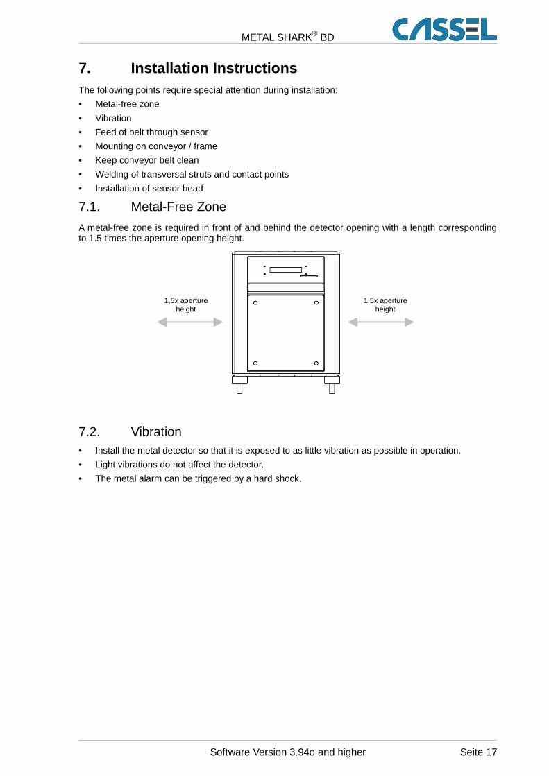
7.1. Metal-Free Zone
A metal-free zone is required in front of and behind the detector opening with a length correspondingto 1.5 times the aperture opening height.
7.2. Vibration• Install the metal detector so that it is exposed to as little vibration as possible in operation.
• Light vibrations do not affect the detector.
• The metal alarm can be triggered by a hard shock.
Software Version 3.94o and higher Seite 17
1,5x apertureheight
1,5x apertureheight
METAL SHARK® BD
7.3. Feed of Belt Through Sensor• The detector is installed in the upper run of a conveyor belt.
• The transport belt is fed through the detector on a non-metallic guide plate (such as a 16 mmplywood sheet) or tensioned to pass through the detector without contact.
• A minimum clearance of 5 mm must be maintained between the guide plate and the detector.
• The inside of the detector opening may not be touched by the guide plate, belt or fibre mat.
7.4. Mounting on Conveyor / Frame• Ensure even and stable contact between detector and mounting bracket.
• The metal detector must not be subjected to any mechanical stress or tension during theinstallation and during tightening of the mounting bolts.
• Before installing, scrape off paint from the conveyor or mounting frame around all of the mountingholes for the metal detector. All of the mounting bolts must have good electrical contact to theconveyor or mounting frame.
7.5. Keep Conveyor Belt Clean
The transport belt must be kept absolutely clean. Even small metal particles and contamination couldtrigger a metal alarm on cycle of the transport belt.
The conveyor must be cleaned of metal swarf and dus t before installation. Do not unpack the beltuntil immediately before installation.
• Do not walk on the conveyor belt without clean protective shoe covers or other protectivemeasures. Visible or invisible shoe prints may contain metal particles.
• Ensure that the belt is well-covered, e.g. with cardboard, before welding or grinding. Hot weldingslag or grinding sparks can embed themselves in the surface of the belt.
7.6. Installation of Sensor Head
Important! The sensor head must not be subjected to any mechan ical stressor tension during the installation and during tight ening of the mounting bolts.
Install sensor head with any support frame:
• Clients support holder construction must be made of stainless steel. Do not paint the construction(to ensure good electrical contact between all metal parts)!
• All of the welding points or mounting bolts in and around the installing frame must give very goodelectrical contact.
Caution! Always attach the grounding clamp of the welding un it directly nextto the welding spot. Do not allow welding current t o flow through the case ofthe metal detector under any circumstances. This wi ll lead to the destructionof the detector!
Seite 18 Software Version 3.94o and higher
METAL SHARK® BD
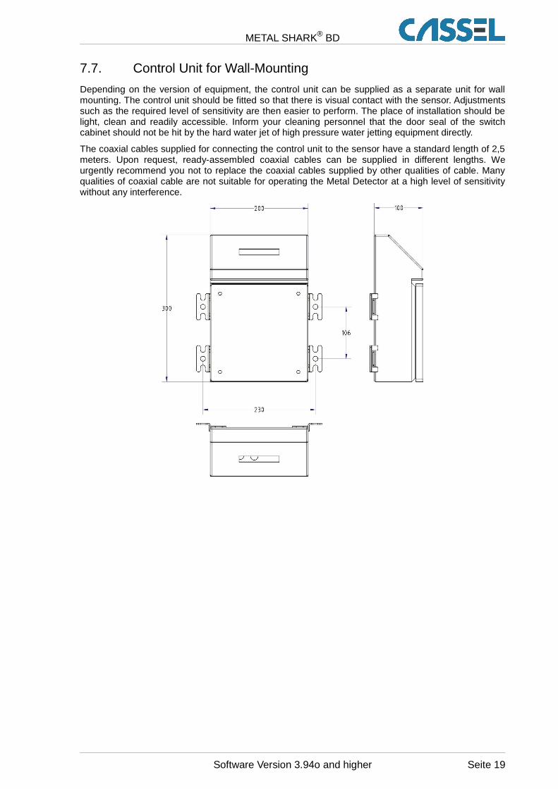
7.7. Control Unit for Wall-Mounting
Depending on the version of equipment, the control unit can be supplied as a separate unit for wallmounting. The control unit should be fitted so that there is visual contact with the sensor. Adjustmentssuch as the required level of sensitivity are then easier to perform. The place of installation should belight, clean and readily accessible. Inform your cleaning personnel that the door seal of the switchcabinet should not be hit by the hard water jet of high pressure water jetting equipment directly.
The coaxial cables supplied for connecting the control unit to the sensor have a standard length of 2,5meters. Upon request, ready-assembled coaxial cables can be supplied in different lengths. Weurgently recommend you not to replace the coaxial cables supplied by other qualities of cable. Manyqualities of coaxial cable are not suitable for operating the Metal Detector at a high level of sensitivitywithout any interference.
Software Version 3.94o and higher Seite 19
METAL SHARK® BD
8. Operating Instructions
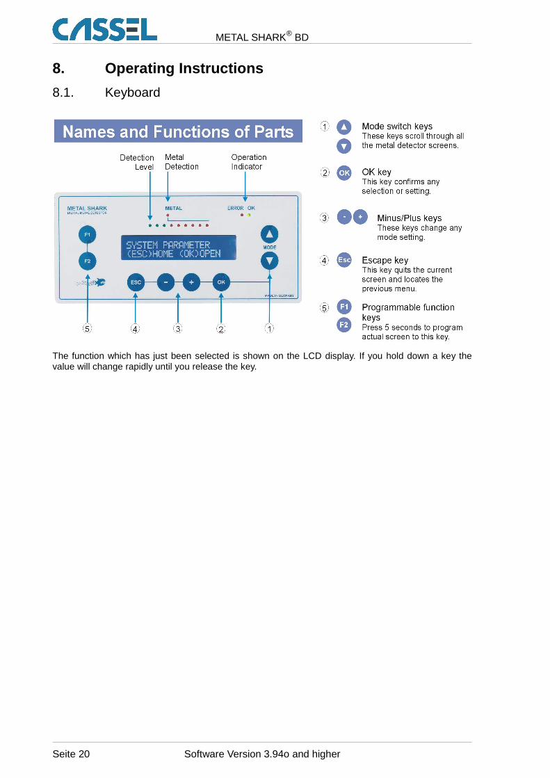
8.1. Keyboard
The function which has just been selected is shown on the LCD display. If you hold down a key thevalue will change rapidly until you release the key.
Seite 20 Software Version 3.94o and higher
METAL SHARK® BD
8.2. Menu Structure
The keys , and are used to navigate through the user interface.
Press several times to return to the main screen (the main screen is displayed after starting themetal detector).
When working with PRODUCT 1 – 120 you can press to go to the teach assistant (TEACHPRODUCT), as well as to change the product specific settings PRODUCT TOL and METAL SENSE
mV (only if EXPERT MODE = YES). When working with PRODUCT 000 you can press to see thesetting METAL SENSE mV.
The TEACH PRODUCT assistant allows you to choose the product characteristics. Then itautomatically adjusts the signal analysis of the metal detector to the products which are suppliedduring the teach process.
Teaching of products is described in detail in the sections “8.3 Product Effect Compensation:Background Information” and “8.4 Starting Up”.
The last menu entry is OPEN MENU. When you press you come to the main menu. Here you can
navigate through the other menus and sub-menus of the metal detector using the keys .
For a complete list of accessible menu-items, see the “Parameter List” at the end of this manual.
The Metal Detector’s Functions in Detail ”9 The Metal Detector’s Functions in Detail”.
REPORT MENU: Information, documentation, and commun ication• The counter for metal alerts (METAL COUNTER)• Characteristic data of the last metal alert (INFO LAST METAL)• Info on current product-related settings (INFO PRODUCT 0xx)• Info on the next performance validation (if activated) and the software version.• Settings for the print-out and data logging of metal alarms and related data (PRINT).• Settings to integrate several detectors into a network, or communicate with a PC (INTERFACE, BAUD,
SHARKNET UNIT #).• A list of the latest 50 metal alerts, providing signal magnitudes and time of alert, which can be printed
(REPORT TO PRINTER) or viewed in the display (REPORT TO LCD).
PRODUCT MENU: Settings which are specific to an ind ividual product• The taught product can be NAMEd in alphanumeric format to be easily memorized. • Settings as obtained after TEACH PRODUCT (PRODUCT IS, AMP X %, AMP Y %, PRODUCT X TOL,
PRODUCT Y TOL, PHASE, PHASE TRACK)• Automatic PHASE TRACKing for products with continuously changing properties• Transfer of settings to other product number (COPY PROD.)
TEACH MENU: General settings to control the TEACH P RODUCT – assistant• A minimum value of METAL SENSE which can be set by TEACH PRODUCT (SENSE MIN).• Settings for the duration and minimum product count during TEACH PRODUCT• Lock / unlock product number to 0 (no product teach possible – TEACH ENABLE NO)• Reject – behaviour during TEACH PRODUCT
VALIDATION MENU: Supervision of proper operation• Supervision of automatic reject devices (REJECT CONFIRM, BIN FULL, LOW AIR)• The PERFORMANCE VALIDATION SYSTEM menu to enforce periodical tests checking the metal sensitivity
SYSTEM MENU: General configuration of the metal det ector (several submenus)• Product SPEED, PASSWORD protection and REMOTE PRODUCT-number control.• Date and time (YY/MM/DD, HH:MM:SS)• Setup of the control signal to the reject device (DELAY, DURATION, METAL CONTACT)• Automatic belt-SPEED calibration of conveyors driven from frequency inverters• Clean In Place switching of the reject device for SHARK-Inline-Models• Setup of the Input and Output control lines (24Vdc switching)• Choice and setup of digital filters (NOISE LEVEL, FFT FILTER, FIR FILTER, GF MODE)• Individual factory settings for the delivered sensor head, which must not be changed by the user (FACTORY
SETUP).
Software Version 3.94o and higher Seite 21
METAL SHARK® BD
8.3. Product Effect Compensation: Background Information
Many products, especially in the food industry, generate an effect similar to metal parts when theyenter the electromagnetic field. This effect is caused by conductive components in the product (e.g.salt, sugar) and is called 'product effect'.
To enable the metal detector to recognize whether the signal coming from the sensor is caused by theproduct being monitored or by a metal part, you must teach the product effect to the metal detector.The product effect is learned on the basis of product samples which have to be passed through thesensor. The product effect may vary from one product sample to another. The better the samplesrepresent the product, the better the product effect will be learned.
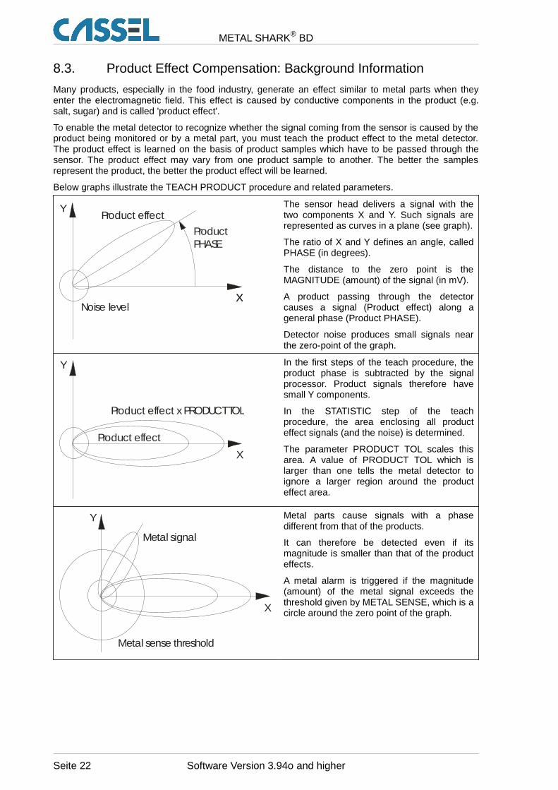
Below graphs illustrate the TEACH PRODUCT procedure and related parameters.
XX
Y
Noise level
Product effect
Product PHASE
The sensor head delivers a signal with thetwo components X and Y. Such signals arerepresented as curves in a plane (see graph).
The ratio of X and Y defines an angle, calledPHASE (in degrees).
The distance to the zero point is theMAGNITUDE (amount) of the signal (in mV).
A product passing through the detectorcauses a signal (Product effect) along ageneral phase (Product PHASE).
Detector noise produces small signals nearthe zero-point of the graph.
X
Y
Product effect x PRODUCT TOL
Product effect
In the first steps of the teach procedure, theproduct phase is subtracted by the signalprocessor. Product signals therefore havesmall Y components.
In the STATISTIC step of the teachprocedure, the area enclosing all producteffect signals (and the noise) is determined.
The parameter PRODUCT TOL scales thisarea. A value of PRODUCT TOL which islarger than one tells the metal detector toignore a larger region around the producteffect area.
X
Y
Metal sense threshold
Metal signal
Metal parts cause signals with a phasedifferent from that of the products.
It can therefore be detected even if itsmagnitude is smaller than that of the producteffects.
A metal alarm is triggered if the magnitude(amount) of the metal signal exceeds thethreshold given by METAL SENSE, which is acircle around the zero point of the graph.
Seite 22 Software Version 3.94o and higher
METAL SHARK® BD
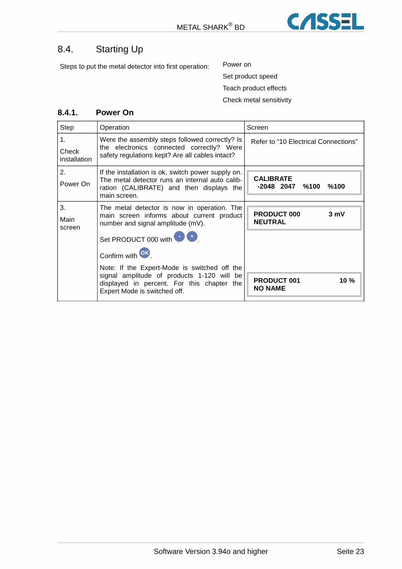
8.4. Starting Up
Steps to put the metal detector into first operation: Power on
Set product speed
Teach product effects
Check metal sensitivity
8.4.1. Power On
Step Operation Screen
1.
Checkinstallation
Were the assembly steps followed correctly? Isthe electronics connected correctly? Weresafety regulations kept? Are all cables intact?
Refer to “10 Electrical Connections”
2.
Power On
If the installation is ok, switch power supply on.The metal detector runs an internal auto calib-ration (CALIBRATE) and then displays themain screen.
CALIBRATE -2048 2047 %100 %100
3.
Mainscreen
The metal detector is now in operation. Themain screen informs about current productnumber and signal amplitude (mV).
Set PRODUCT 000 with .
Confirm with .
Note: If the Expert-Mode is switched off thesignal amplitude of products 1-120 will bedisplayed in percent. For this chapter theExpert Mode is switched off.
PRODUCT 000 3 mVNEUTRAL
PRODUCT 001 10 %NO NAME
Software Version 3.94o and higher Seite 23
METAL SHARK® BD
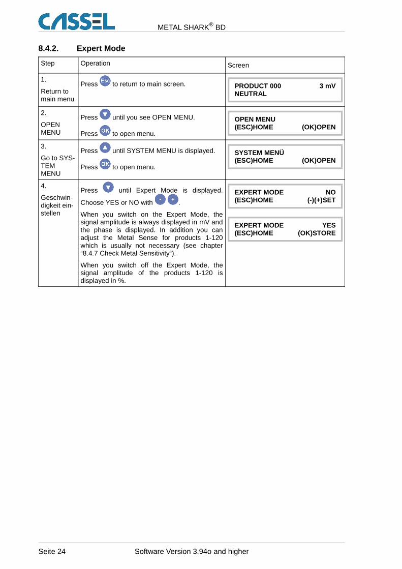
8.4.2. Expert Mode
Step Operation Screen
1.
Return tomain menu
Press to return to main screen. PRODUCT 000 3 mVNEUTRAL
2.
OPENMENU
Press until you see OPEN MENU.
Press to open menu.
OPEN MENU(ESC)HOME (OK)OPEN
3.
Go to SYS-TEMMENU
Press until SYSTEM MENU is displayed.
Press to open menu.
SYSTEM MENÜ(ESC)HOME (OK)OPEN
4.
Geschwin-digkeit ein-stellen
Press until Expert Mode is displayed.
Choose YES or NO with .
When you switch on the Expert Mode, thesignal amplitude is always displayed in mV andthe phase is displayed. In addition you canadjust the Metal Sense for products 1-120which is usually not necessary (see chapter“8.4.7 Check Metal Sensitivity“).
When you switch off the Expert Mode, thesignal amplitude of the products 1-120 isdisplayed in %.
EXPERT MODE NO(ESC)HOME (-)(+)SET
EXPERT MODE YES(ESC)HOME (OK)STORE
Seite 24 Software Version 3.94o and higher
METAL SHARK® BD
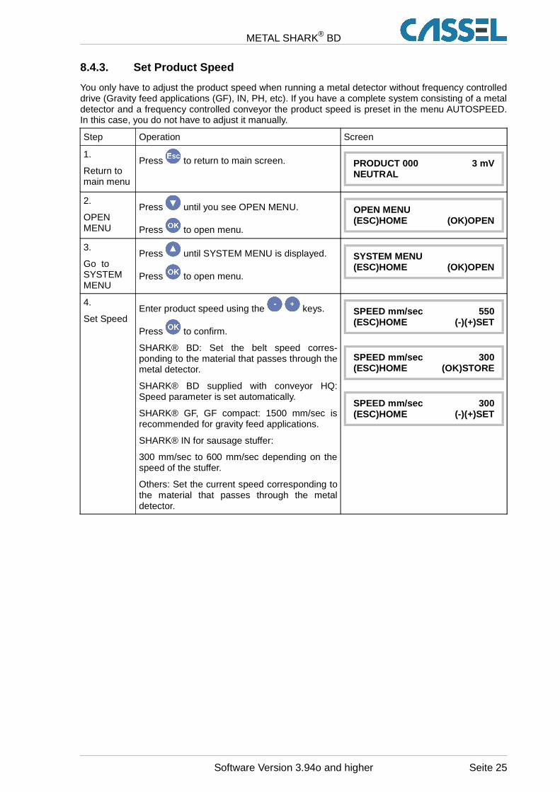
8.4.3. Set Product Speed
You only have to adjust the product speed when running a metal detector without frequency controlleddrive (Gravity feed applications (GF), IN, PH, etc). If you have a complete system consisting of a metaldetector and a frequency controlled conveyor the product speed is preset in the menu AUTOSPEED.In this case, you do not have to adjust it manually.
Step Operation Screen
1.
Return tomain menu
Press to return to main screen. PRODUCT 000 3 mVNEUTRAL
2.
OPENMENU
Press until you see OPEN MENU.
Press to open menu.
OPEN MENU(ESC)HOME (OK)OPEN
3.
Go toSYSTEMMENU
Press until SYSTEM MENU is displayed.
Press to open menu.
SYSTEM MENU(ESC)HOME (OK)OPEN
4.
Set SpeedEnter product speed using the keys.
Press to confirm.
SHARK® BD: Set the belt speed corres-ponding to the material that passes through themetal detector.
SHARK® BD supplied with conveyor HQ:Speed parameter is set automatically.
SHARK® GF, GF compact: 1500 mm/sec isrecommended for gravity feed applications.
SHARK® IN for sausage stuffer:
300 mm/sec to 600 mm/sec depending on thespeed of the stuffer.
Others: Set the current speed corresponding tothe material that passes through the metaldetector.
SPEED mm/sec 550(ESC)HOME (-)(+)SET
SPEED mm/sec 300(ESC)HOME (OK)STORE
SPEED mm/sec 300(ESC)HOME (-)(+)SET
Software Version 3.94o and higher Seite 25
METAL SHARK® BD
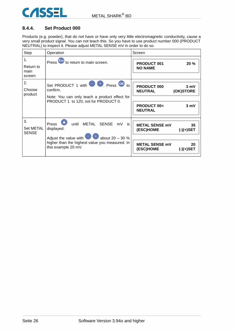
8.4.4. Set Product 000
Products (e.g. powder), that do not have or have only very little electromagnetic conductivity, cause avery small product signal. You can not teach this. So you have to use product number 000 (PRODUCTNEUTRAL) to inspect it. Please adjust METAL SENSE mV in order to do so.
Step Operation Screen
1.
Return tomainscreen
Press to return to main screen. PRODUCT 001 20 %NO NAME
2.
Chooseproduct
Set PRODUCT 1 with . Press toconfirm.
Note: You can only teach a product effect forPRODUCT 1 to 120, not for PRODUCT 0.
PRODUCT 000 3 mVNEUTRAL (OK)STORE
PRODUCT 00= 3 mVNEUTRAL
3.
Set METALSENSE
Press until METAL SENSE mV isdisplayed.
Adjust the value with about 20 – 30 %higher than the highest value you measured. Inthis example 20 mV.
METAL SENSE mV 35(ESC)HOME (-)(+)SET
METAL SENSE mV 20(ESC)HOME (-)(+)SET
Seite 26 Software Version 3.94o and higher
METAL SHARK® BD
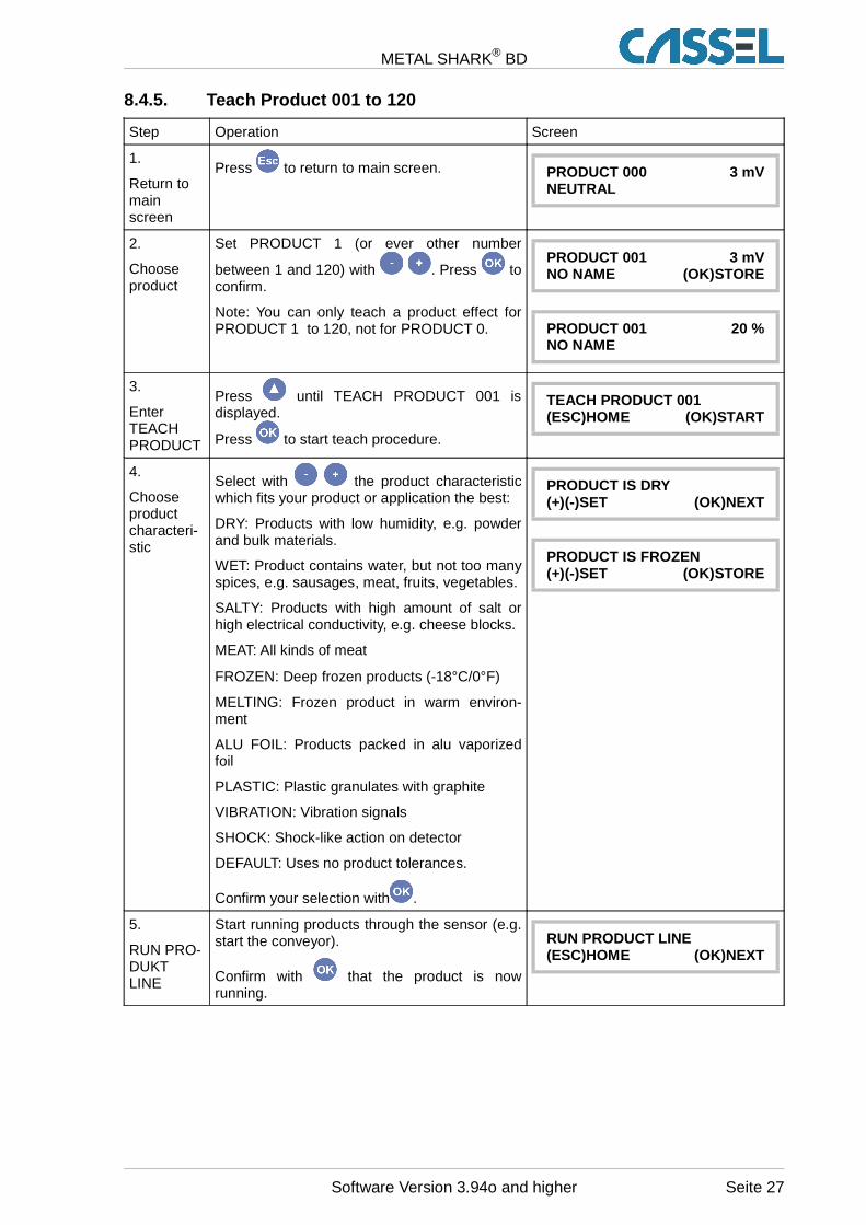
8.4.5. Teach Product 001 to 120
Step Operation Screen
1.
Return tomainscreen
Press to return to main screen. PRODUCT 000 3 mVNEUTRAL
2.
Chooseproduct
Set PRODUCT 1 (or ever other number
between 1 and 120) with . Press toconfirm.
Note: You can only teach a product effect forPRODUCT 1 to 120, not for PRODUCT 0.
PRODUCT 001 3 mVNO NAME (OK)STORE
PRODUCT 001 20 %NO NAME
3.
EnterTEACHPRODUCT
Press until TEACH PRODUCT 001 isdisplayed.
Press to start teach procedure.
TEACH PRODUCT 001(ESC)HOME (OK)START
4.
Chooseproductcharacteri-stic
Select with the product characteristicwhich fits your product or application the best:
DRY: Products with low humidity, e.g. powderand bulk materials.
WET: Product contains water, but not too manyspices, e.g. sausages, meat, fruits, vegetables.
SALTY: Products with high amount of salt orhigh electrical conductivity, e.g. cheese blocks.
MEAT: All kinds of meat
FROZEN: Deep frozen products (-18°C/0°F)
MELTING: Frozen product in warm environ-ment
ALU FOIL: Products packed in alu vaporizedfoil
PLASTIC: Plastic granulates with graphite
VIBRATION: Vibration signals
SHOCK: Shock-like action on detector
DEFAULT: Uses no product tolerances.
Confirm your selection with .
PRODUCT IS DRY(+)(-)SET (OK)NEXT
PRODUCT IS FROZEN(+)(-)SET (OK)STORE
5.
RUN PRO-DUKTLINE
Start running products through the sensor (e.g.start the conveyor).
Confirm with that the product is nowrunning.
RUN PRODUCT LINE(ESC)HOME (OK)NEXT
Software Version 3.94o and higher Seite 27
METAL SHARK® BD
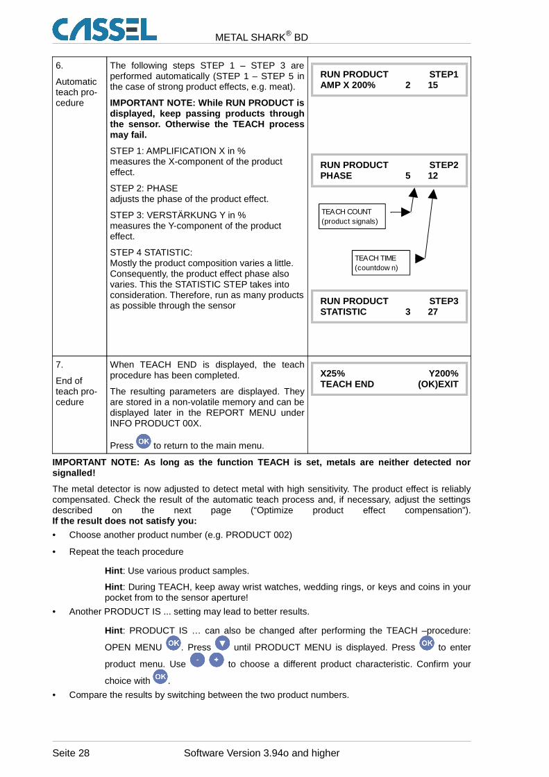
6.
Automaticteach pro-cedure
The following steps STEP 1 – STEP 3 areperformed automatically (STEP 1 – STEP 5 inthe case of strong product effects, e.g. meat).
IMPORTANT NOTE: While RUN PRODUCT isdisplayed, keep passing products throughthe sensor. Otherwise the TEACH processmay fail.
STEP 1: AMPLIFICATION X in %measures the X-component of the producteffect.
STEP 2: PHASEadjusts the phase of the product effect.
STEP 3: VERSTÄRKUNG Y in %measures the Y-component of the producteffect.
STEP 4 STATISTIC: Mostly the product composition varies a little.Consequently, the product effect phase alsovaries. This the STATISTIC STEP takes intoconsideration. Therefore, run as many productsas possible through the sensor
RUN PRODUCT STEP1AMP X 200% 2 15
RUN PRODUCT STEP2PHASE 5 12
RUN PRODUCT STEP3STATISTIC 3 27
7.
End ofteach pro-cedure
When TEACH END is displayed, the teachprocedure has been completed.
The resulting parameters are displayed. Theyare stored in a non-volatile memory and can bedisplayed later in the REPORT MENU underINFO PRODUCT 00X.
Press to return to the main menu.
X25% Y200%TEACH END (OK)EXIT
IMPORTANT NOTE: As long as the function TEACH is set, metals are ne ither detected norsignalled!
The metal detector is now adjusted to detect metal with high sensitivity. The product effect is reliablycompensated. Check the result of the automatic teach process and, if necessary, adjust the settingsdescribed on the next page (“Optimize product effect compensation”).If the result does not satisfy you:
• Choose another product number (e.g. PRODUCT 002)
• Repeat the teach procedure
Hint : Use various product samples.
Hint : During TEACH, keep away wrist watches, wedding rings, or keys and coins in yourpocket from to the sensor aperture!
• Another PRODUCT IS ... setting may lead to better results.
Hint : PRODUCT IS … can also be changed after performing the TEACH –procedure:
OPEN MENU . Press until PRODUCT MENU is displayed. Press to enter
product menu. Use to choose a different product characteristic. Confirm your
choice with .
• Compare the results by switching between the two product numbers.
Seite 28 Software Version 3.94o and higher
TEACH COUNT(product signals)
TEACH TIME(countdow n)
METAL SHARK® BD
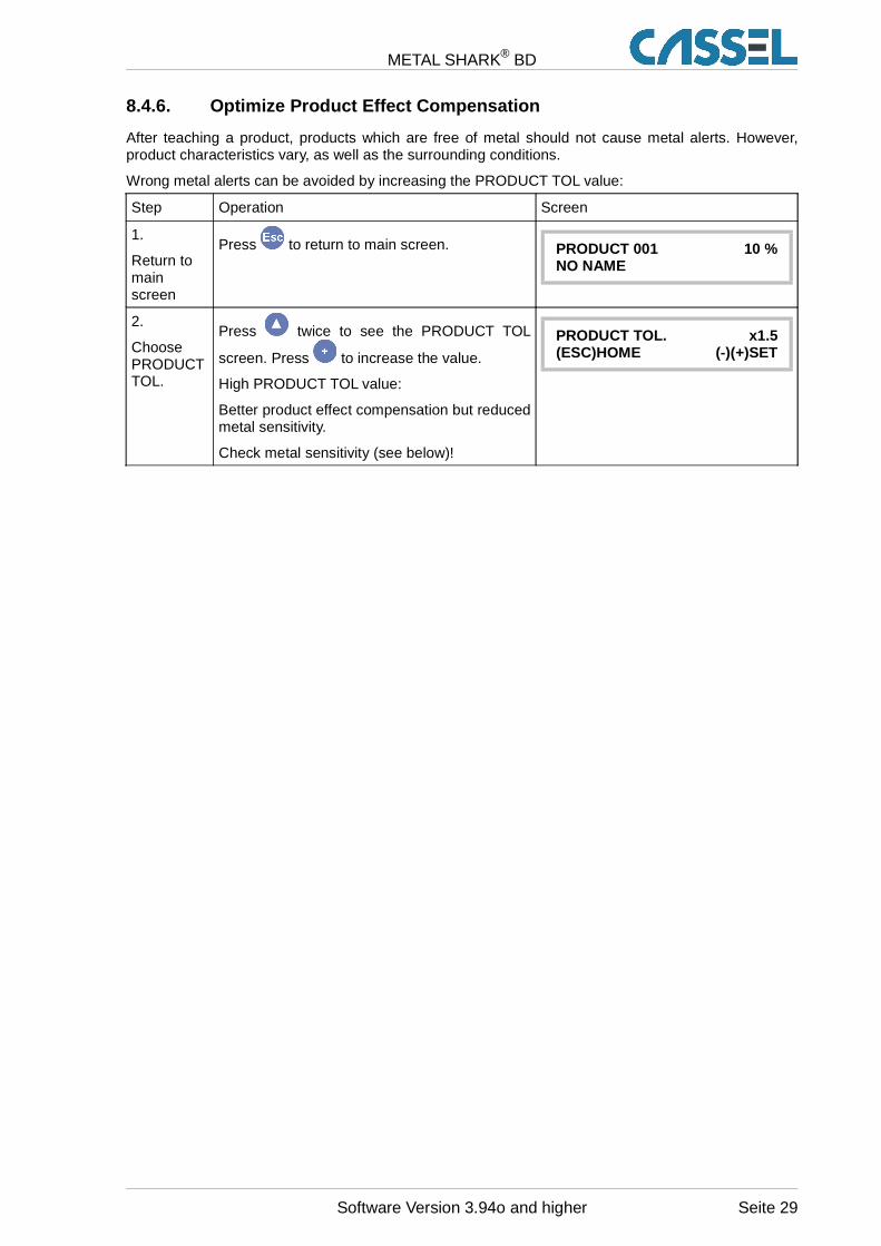
8.4.6. Optimize Product Effect Compensation
After teaching a product, products which are free of metal should not cause metal alerts. However,product characteristics vary, as well as the surrounding conditions.
Wrong metal alerts can be avoided by increasing the PRODUCT TOL value:
Step Operation Screen
1.
Return tomainscreen
Press to return to main screen. PRODUCT 001 10 %NO NAME
2.
ChoosePRODUCTTOL.
Press twice to see the PRODUCT TOL
screen. Press to increase the value.
High PRODUCT TOL value:
Better product effect compensation but reducedmetal sensitivity.
Check metal sensitivity (see below)!
PRODUCT TOL. x1.5(ESC)HOME (-)(+)SET
Software Version 3.94o and higher Seite 29
METAL SHARK® BD
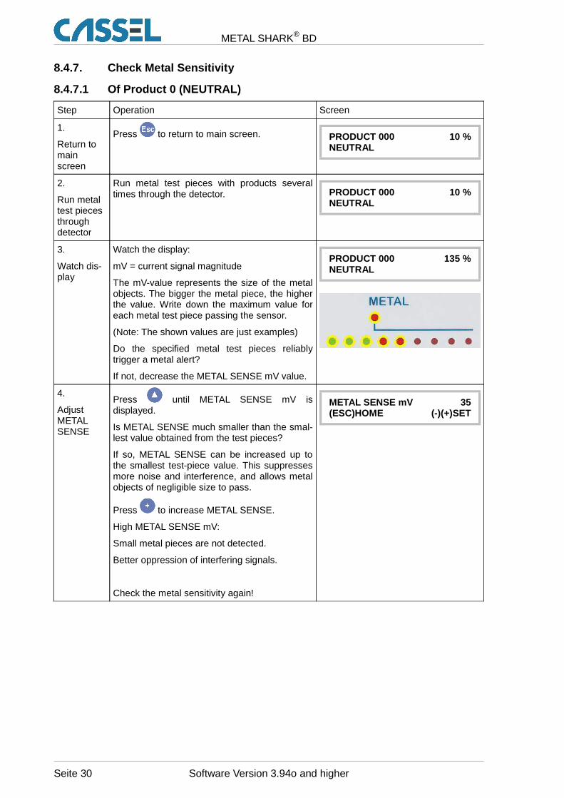
8.4.7. Check Metal Sensitivity
8.4.7.1 Of Product 0 (NEUTRAL)
Step Operation Screen
1.
Return tomainscreen
Press to return to main screen. PRODUCT 000 10 %NEUTRAL
2.
Run metaltest piecesthroughdetector
Run metal test pieces with products severaltimes through the detector. PRODUCT 000 10 %
NEUTRAL
3.
Watch dis-play
Watch the display:
mV = current signal magnitude
The mV-value represents the size of the metalobjects. The bigger the metal piece, the higherthe value. Write down the maximum value foreach metal test piece passing the sensor.
(Note: The shown values are just examples)
Do the specified metal test pieces reliablytrigger a metal alert?
If not, decrease the METAL SENSE mV value.
PRODUCT 000 135 %NEUTRAL
4.
AdjustMETALSENSE
Press until METAL SENSE mV isdisplayed.
Is METAL SENSE much smaller than the smal-lest value obtained from the test pieces?
If so, METAL SENSE can be increased up tothe smallest test-piece value. This suppressesmore noise and interference, and allows metalobjects of negligible size to pass.
Press to increase METAL SENSE.
High METAL SENSE mV:
Small metal pieces are not detected.
Better oppression of interfering signals.
Check the metal sensitivity again!
METAL SENSE mV 35(ESC)HOME (-)(+)SET
Seite 30 Software Version 3.94o and higher
METAL SHARK® BD
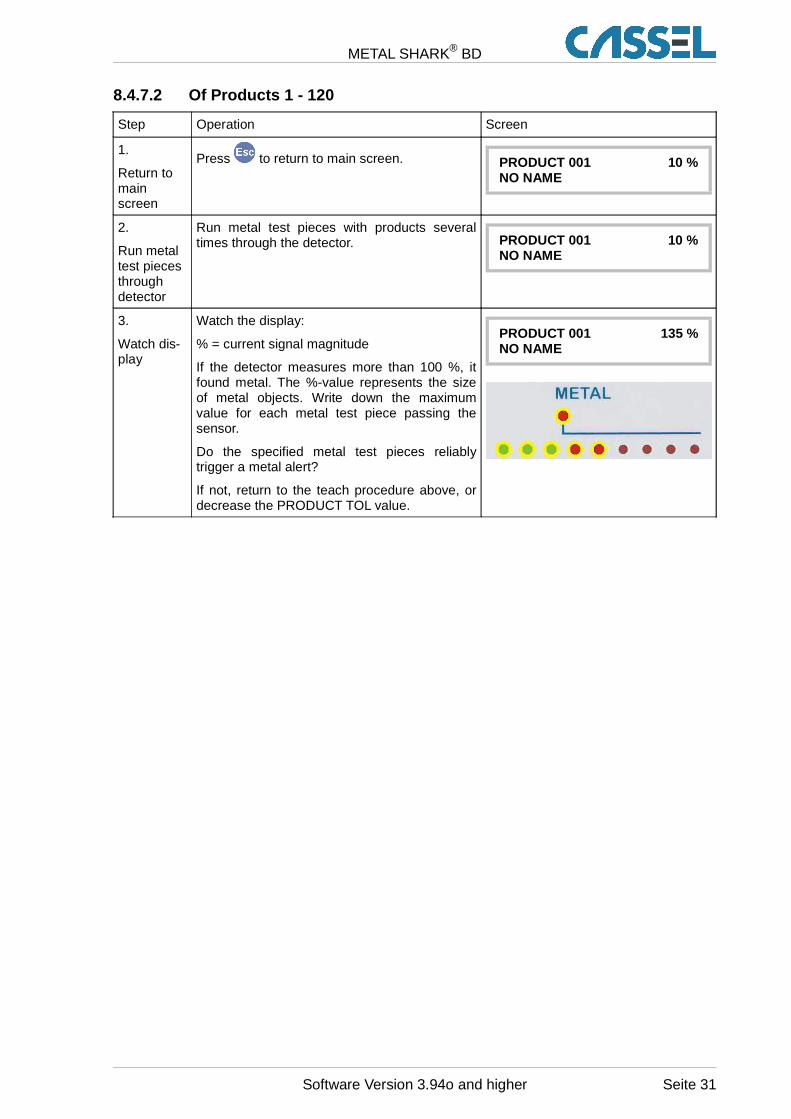
8.4.7.2 Of Products 1 - 120
Step Operation Screen
1.
Return tomainscreen
Press to return to main screen. PRODUCT 001 10 %NO NAME
2.
Run metaltest piecesthroughdetector
Run metal test pieces with products severaltimes through the detector. PRODUCT 001 10 %
NO NAME
3.
Watch dis-play
Watch the display:
% = current signal magnitude
If the detector measures more than 100 %, itfound metal. The %-value represents the sizeof metal objects. Write down the maximumvalue for each metal test piece passing thesensor.
Do the specified metal test pieces reliablytrigger a metal alert?
If not, return to the teach procedure above, ordecrease the PRODUCT TOL value.
PRODUCT 001 135 %NO NAME
Software Version 3.94o and higher Seite 31
METAL SHARK® BD
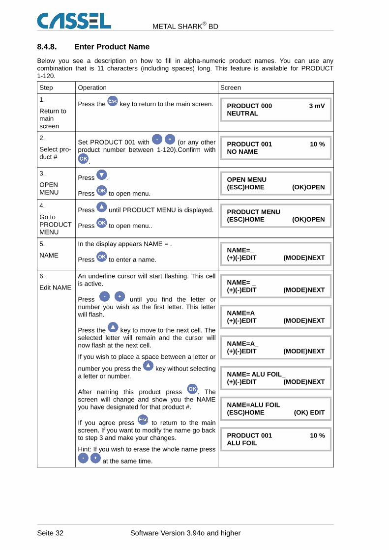
8.4.8. Enter Product Name
Below you see a description on how to fill in alpha-numeric product names. You can use anycombination that is 11 characters (including spaces) long. This feature is available for PRODUCT1-120.
Step Operation Screen
1.
Return tomainscreen
Press the key to return to the main screen. PRODUCT 000 3 mVNEUTRAL
2.
Select pro-duct #
Set PRODUCT 001 with (or any otherproduct number between 1-120).Confirm with
.
PRODUCT 001 10 %NO NAME
3.
OPENMENU
Press .
Press to open menu.
OPEN MENU(ESC)HOME (OK)OPEN
4.
Go toPRODUCTMENU
Press until PRODUCT MENU is displayed.
Press to open menu..
PRODUCT MENU(ESC)HOME (OK)OPEN
5.
NAME
In the display appears NAME = .
Press to enter a name.
NAME=_(+)(-)EDIT (MODE)NEXT
6.
Edit NAME
An underline cursor will start flashing. This cellis active.
Press until you find the letter ornumber you wish as the first letter. This letterwill flash.
Press the key to move to the next cell. Theselected letter will remain and the cursor willnow flash at the next cell.
If you wish to place a space between a letter or
number you press the key without selectinga letter or number.
After naming this product press . Thescreen will change and show you the NAMEyou have designated for that product #.
If you agree press to return to the mainscreen. If you want to modify the name go backto step 3 and make your changes.
Hint: If you wish to erase the whole name press
at the same time.
NAME= _(+)(-)EDIT (MODE)NEXT
NAME=A(+)(-)EDIT (MODE)NEXT
NAME=A_(+)(-)EDIT (MODE)NEXT
NAME= ALU FOIL_(+)(-)EDIT (MODE)NEXT
NAME=ALU FOIL(ESC)HOME (OK) EDIT
PRODUCT 001 10 %ALU FOIL
Seite 32 Software Version 3.94o and higher
METAL SHARK® BD
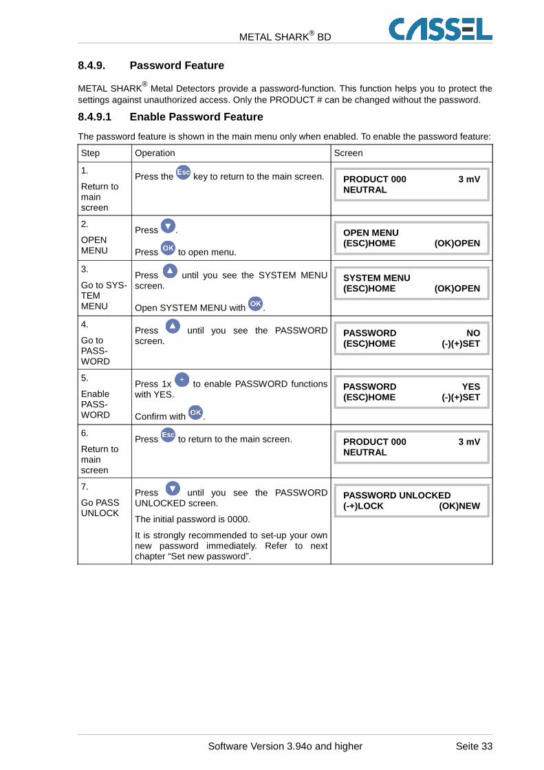
8.4.9. Password Feature
METAL SHARK® Metal Detectors provide a password-function. This function helps you to protect thesettings against unauthorized access. Only the PRODUCT # can be changed without the password.
8.4.9.1 Enable Password Feature
The password feature is shown in the main menu only when enabled. To enable the password feature:
Step Operation Screen
1.
Return tomainscreen
Press the key to return to the main screen. PRODUCT 000 3 mVNEUTRAL
2.
OPENMENU
Press .
Press to open menu.
OPEN MENU(ESC)HOME (OK)OPEN
3.
Go to SYS-TEMMENU
Press until you see the SYSTEM MENUscreen.
Open SYSTEM MENU with .
SYSTEM MENU(ESC)HOME (OK)OPEN
4.
Go toPASS-WORD
Press until you see the PASSWORDscreen.
PASSWORD NO(ESC)HOME (-)(+)SET
5.
EnablePASS-WORD
Press 1x to enable PASSWORD functionswith YES.
Confirm with .
PASSWORD YES(ESC)HOME (-)(+)SET
6.
Return tomainscreen
Press to return to the main screen. PRODUCT 000 3 mVNEUTRAL
7.
Go PASSUNLOCK
Press until you see the PASSWORDUNLOCKED screen.
The initial password is 0000.
It is strongly recommended to set-up your ownnew password immediately. Refer to nextchapter “Set new password”.
PASSWORD UNLOCKED(-+)LOCK (OK)NEW
Software Version 3.94o and higher Seite 33
METAL SHARK® BD
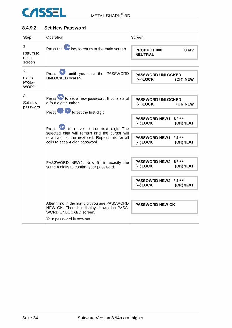
8.4.9.2 Set New Password
Step Operation Screen
1.
Return tomainscreen
Press the key to return to the main screen. PRODUCT 000 3 mVNEUTRAL
2.
Go toPASS-WORD
Press until you see the PASSWORDUNLOCKED screen.
PASSWORD UNLOCKED (-+)LOCK (OK) NEW
3.
Set newpassword
Press to set a new password. It consists ofa four digit number.
Press to set the first digit.
Press to move to the next digit. Theselected digit will remain and the cursor willnow flash at the next cell. Repeat this for allcells to set a 4 digit password.
PASSWORD NEW2: Now fill in exactly thesame 4 digits to confirm your password.
After filling in the last digit you see PASSWORDNEW OK. Then the display shows the PASS-WORD UNLOCKED screen.
Your password is now set.
PASSWORD UNLOCKED (-+)LOCK (OK)NEW
PASSWORD NEW1 8 * * *(-+)LOCK (OK)NEXT
PASSWORD NEW1 * 4 * *(-+)LOCK (OK)NEXT
PASSWORD NEW2 8 * * *(-+)LOCK (OK)NEXT
PASSOWRD NEW2 * 4 * *(-+)LOCK (OK)NEXT
PASSWORD NEW OK
Seite 34 Software Version 3.94o and higher
METAL SHARK® BD
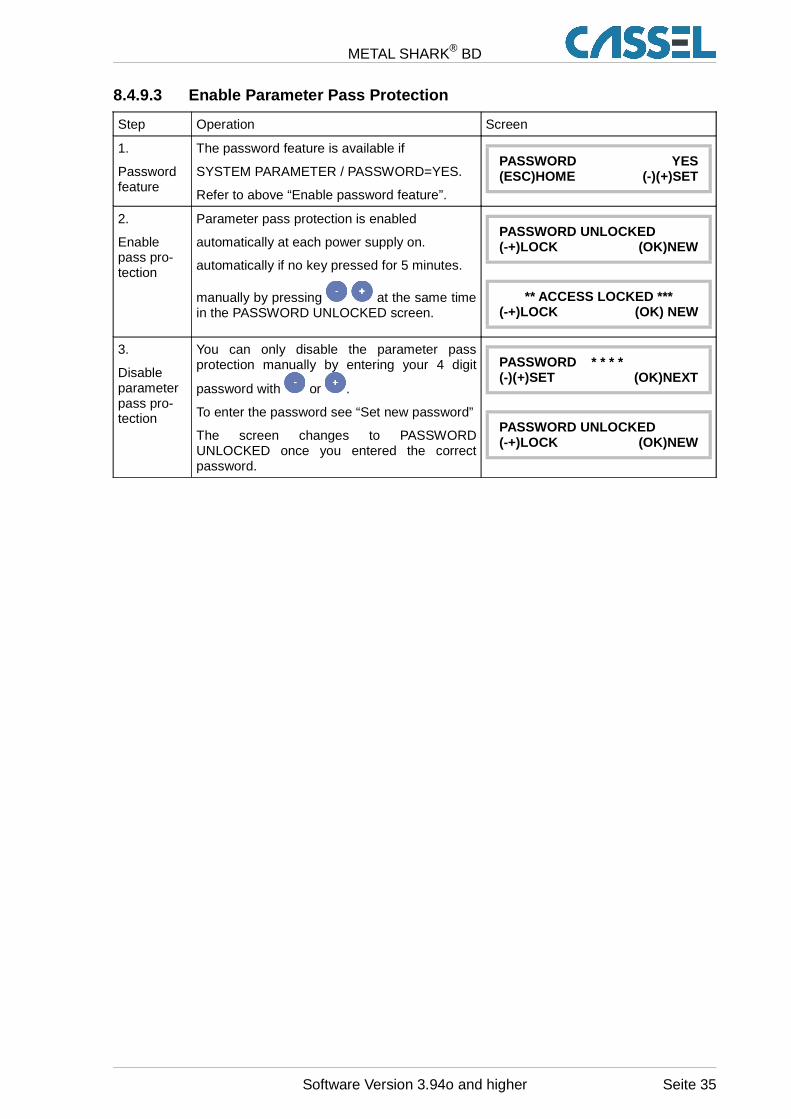
8.4.9.3 Enable Parameter Pass Protection
Step Operation Screen
1.
Passwordfeature
The password feature is available if
SYSTEM PARAMETER / PASSWORD=YES.
Refer to above “Enable password feature”.
PASSWORD YES(ESC)HOME (-)(+)SET
2.
Enablepass pro-tection
Parameter pass protection is enabled
automatically at each power supply on.
automatically if no key pressed for 5 minutes.
manually by pressing at the same timein the PASSWORD UNLOCKED screen.
PASSWORD UNLOCKED(-+)LOCK (OK)NEW
** ACCESS LOCKED ***(-+)LOCK (OK) NEW
3.
Disableparameterpass pro-tection
You can only disable the parameter passprotection manually by entering your 4 digit
password with or .
To enter the password see “Set new password”
The screen changes to PASSWORDUNLOCKED once you entered the correctpassword.
PASSWORD * * * *(-)(+)SET (OK)NEXT
PASSWORD UNLOCKED(-+)LOCK (OK)NEW
Software Version 3.94o and higher Seite 35
METAL SHARK® BD
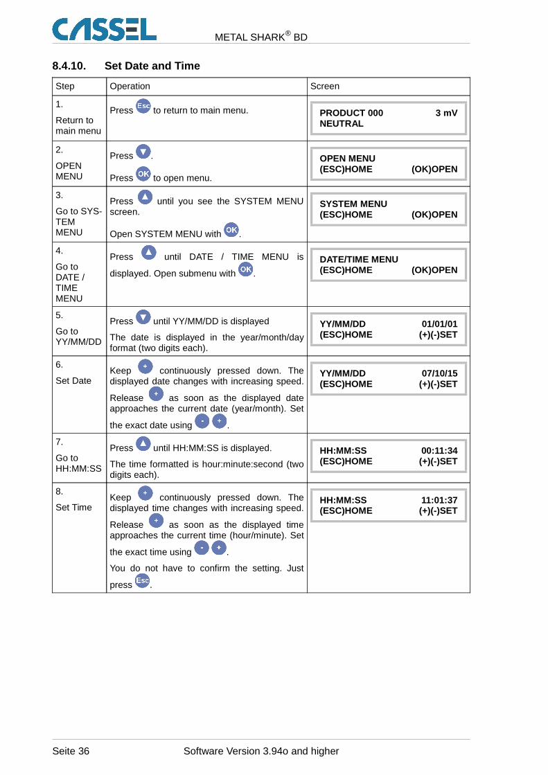
8.4.10. Set Date and Time
Step Operation Screen
1.
Return tomain menu
Press to return to main menu. PRODUCT 000 3 mVNEUTRAL
2.
OPENMENU
Press .
Press to open menu.
OPEN MENU(ESC)HOME (OK)OPEN
3.
Go to SYS-TEMMENU
Press until you see the SYSTEM MENUscreen.
Open SYSTEM MENU with .
SYSTEM MENU(ESC)HOME (OK)OPEN
4.
Go toDATE /TIMEMENU
Press until DATE / TIME MENU is
displayed. Open submenu with .
DATE/TIME MENU(ESC)HOME (OK)OPEN
5.
Go toYY/MM/DD
Press until YY/MM/DD is displayed
The date is displayed in the year/month/dayformat (two digits each).
YY/MM/DD 01/01/01(ESC)HOME (+)(-)SET
6.
Set DateKeep continuously pressed down. Thedisplayed date changes with increasing speed.
Release as soon as the displayed dateapproaches the current date (year/month). Set
the exact date using .
YY/MM/DD 07/10/15(ESC)HOME (+)(-)SET
7.
Go toHH:MM:SS
Press until HH:MM:SS is displayed.
The time formatted is hour:minute:second (twodigits each).
HH:MM:SS 00:11:34(ESC)HOME (+)(-)SET
8.
Set TimeKeep continuously pressed down. Thedisplayed time changes with increasing speed.
Release as soon as the displayed timeapproaches the current time (hour/minute). Set
the exact time using .
You do not have to confirm the setting. Just
press .
HH:MM:SS 11:01:37(ESC)HOME (+)(-)SET
Seite 36 Software Version 3.94o and higher
METAL SHARK® BD
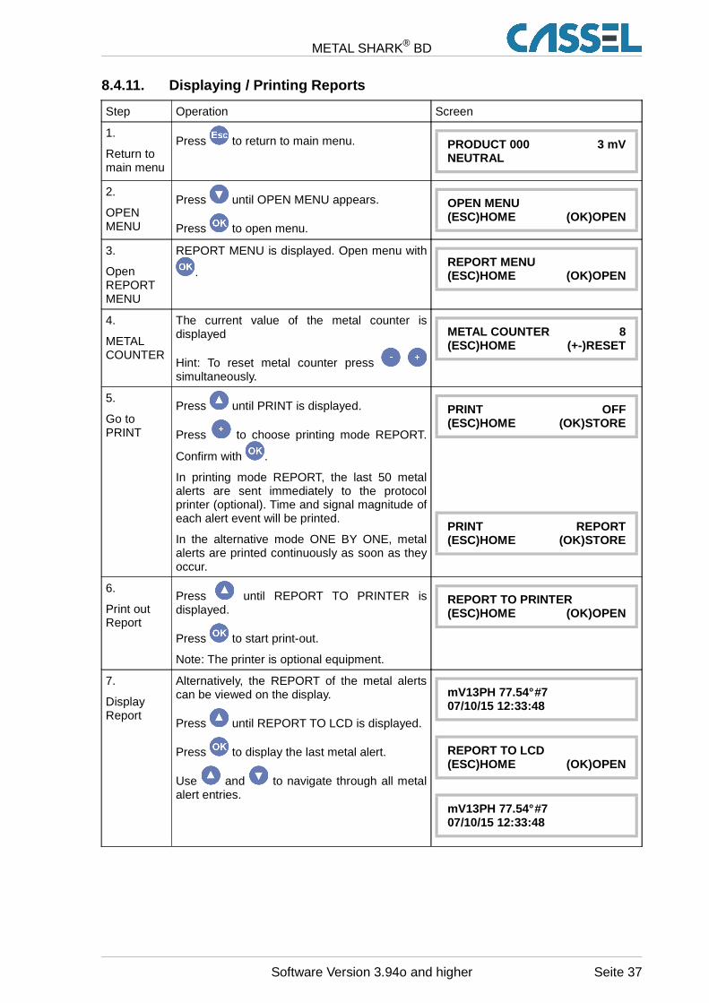
8.4.11. Displaying / Printing Reports
Step Operation Screen
1.
Return tomain menu
Press to return to main menu. PRODUCT 000 3 mVNEUTRAL
2.
OPENMENU
Press until OPEN MENU appears.
Press to open menu.
OPEN MENU(ESC)HOME (OK)OPEN
3.
OpenREPORTMENU
REPORT MENU is displayed. Open menu with
.REPORT MENU(ESC)HOME (OK)OPEN
4.
METALCOUNTER
The current value of the metal counter isdisplayed
Hint: To reset metal counter press simultaneously.
METAL COUNTER 8(ESC)HOME (+-)RESET
5.
Go toPRINT
Press until PRINT is displayed.
Press to choose printing mode REPORT.
Confirm with .
In printing mode REPORT, the last 50 metalalerts are sent immediately to the protocolprinter (optional). Time and signal magnitude ofeach alert event will be printed.
In the alternative mode ONE BY ONE, metalalerts are printed continuously as soon as theyoccur.
PRINT OFF(ESC)HOME (OK)STORE
PRINT REPORT(ESC)HOME (OK)STORE
6.
Print outReport
Press until REPORT TO PRINTER isdisplayed.
Press to start print-out.
Note: The printer is optional equipment.
REPORT TO PRINTER (ESC)HOME (OK)OPEN
7.
DisplayReport
Alternatively, the REPORT of the metal alertscan be viewed on the display.
Press until REPORT TO LCD is displayed.
Press to display the last metal alert.
Use and to navigate through all metalalert entries.
mV13PH 77.54° #707/10/15 12:33:48
REPORT TO LCD(ESC)HOME (OK)OPEN
mV13PH 77.54° #707/10/15 12:33:48
Software Version 3.94o and higher Seite 37
METAL SHARK® BD
9. The Metal Detector’s Functions in Detail
9.1. Main Menu
You always reach the main menu by returning to the main screen (pressing several times). Then
you press until OPEN MENU is displayed. Press to open the menu. Now you can choose
between the metal detector’s menus using .
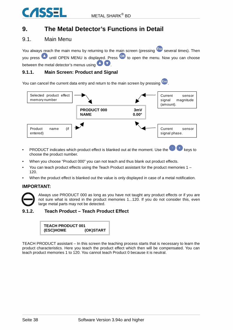
9.1.1. Main Screen: Product and Signal
You can cancel the current data entry and return to the main screen by pressing .
PRODUCT 000 3mVNAME 0.00°
• PRODUCT indicates which product effect is blanked out at the moment. Use the keys tochoose the product number.
• When you choose “Product 000” you can not teach and thus blank out product effects.
• You can teach product effects using the Teach Product assistant for the product memories 1 –120.
• When the product effect is blanked out the value is only displayed in case of a metal notification.
IMPORTANT:
Always use PRODUCT 000 as long as you have not taught any product effects or if you arenot sure what is stored in the product memories 1...120. If you do not consider this, evenlarge metal parts may not be detected.
9.1.2. Teach Product – Teach Product Effect
TEACH PRODUCT 001(ESC)HOME (OK)START
TEACH PRODUCT assistant – In this screen the teaching process starts that is necessary to learn theproduct characteristics. Here you teach the product effect which then will be compensated. You canteach product memories 1 to 120. You cannot teach Product 0 because it is neutral.
Seite 38 Software Version 3.94o and higher
Selected product effect memory number
Current sensor signal magnitude (amount).
Product name (if entered)
Current sensor signal phase.
METAL SHARK® BD
9.1.3. Product Tolerance
PRODUCT TOL x 1.3(ESC)HOME (-)(+)SET
This parameter scales the product effect area. Metal alerts due to variations of the product effect canbe suppressed by increasing PRODUCT TOL. The initial setting depends on the chosen productcharacteristic (PRODUCT IS …).
See chapter “8.3 Product Effect Compensation: Background Information”, “8.4.4 Set Product 000” and“8.4.5 Teach Product 001 to 120” for details.
9.1.4. Metal Sense mV
METAL SENSE mV 50 (ESC)HOME (-)(+)SET
This function allows the operator to specify the minimum signal amplitude of metal parts which have to
be signaled. The mV value can be adjusted in the range of 3 to 3,000 with the keys. WithMETAL SENSE mV 3 the smallest detectable metal parts are signaled. The sensitivity decreaseslinearly with increasing value of METAL SENSE. At 2,999 mV only very large metal parts are signaled.At 3,000 mV the sensor is set to NOT ACTIVE.
To determine which magnitude a particular metal part generates, refer to “9.2.2 Info Last Metal”. Bearin mind that non-spherical metal parts may generate different magnitudes depending on theirorientation. Magnetic metal parts produce a larger signal than non-magnetic metal parts.
IMPORTANT:
The METAL SENSE is preset by the product memory and must be set separately for eachproduct memory, if you work with different product memories 1...120 (mainly used in food-industries).
9.1.5. Info Next PV Test
03/08/27 17:52:06INFO NEXT PV TEST
Default: Not visible
Date and time of the next performance validation are displayed.
This screen is only visible if the performance validation system is activated. See PVS MENU in thechapter VALIDATION MENU below.
Software Version 3.94o and higher Seite 39
METAL SHARK® BD
9.1.6. Open Menu
OPEN MENU(ESC)HOME (OK)OPEN
Press to access the advanced parameter menus described below.
9.1.7. Password
PASSWORD ****(+)(-)SET (OK)NEXT
Default: Not visible.
Enter PASSWORD to make settings. To switch option PASSWORD on/off, go to submenu SYSTEMMENU. Set SYSTEM PARAMETER / PASSWORD = YES.
This screen is only visible if password protection is activated.
See chapter “8.4.9 Password Feature” for a step-by-step introduction.
9.2. Report Menu
The REPORT MENU provides
• information about metal alerts,
• information about the current product parameters and
• settings to control data logging, print-out and network integration.
REPORT MENU(ESC)HOME (OK)OPEN
Press to open the REPORT MENU.
Press at any time to abort your current data entry and return to main menu.
9.2.1. Metal Counter
METAL COUNTER 0(ESC)HOME (-+)RESET
With each metal signal the counter increases.
If the keys are pressed down simultaneously for approx. 2 seconds the counter is reset tozero. This also resets the report memory (see below).
Seite 40 Software Version 3.94o and higher
METAL SHARK® BD
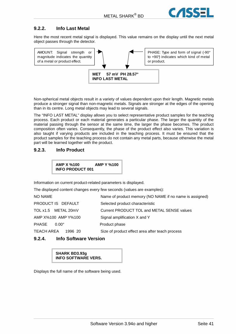
9.2.2. Info Last Metal
Here the most recent metal signal is displayed. This value remains on the display until the next metalobject passes through the detector.
MET 57 mV PH 28.57°INFO LAST METAL
Non-spherical metal objects result in a variety of values dependent upon their length. Magnetic metalsproduce a stronger signal than non-magnetic metals. Signals are stronger at the edges of the openingthan in its centre. Long metal objects may lead to several signals.
The “INFO LAST METAL” display allows you to select representative product samples for the teachingprocess. Each product or each material generates a particular phase. The larger the quantity of thematerial passing through the sensor at the same time, the larger the phase becomes. The productcomposition often varies. Consequently, the phase of the product effect also varies. This variation isalso taught if varying products are included in the teaching process. It must be ensured that theproduct samples for the teaching process do not contain any metal parts, because otherwise the metalpart will be learned together with the product.
9.2.3. Info Product
AMP X %100 AMP Y %100INFO PRODUCT 001
Information on current product-related parameters is displayed.
The displayed content changes every few seconds (values are examples):
NO NAME Name of product memory (NO NAME if no name is assigned)
PRODUCT IS DEFAULT Selected product characteristic
TOL x1.5 METAL 20mV Current PRODUCT TOL and METAL SENSE values
AMP X%100 AMP Y%100 Signal amplification X and Y
PHASE 0.00° Product phase
TEACH AREA 1996 20 Size of product effect area after teach process
9.2.4. Info Software Version
SHARK BD3.93gINFO SOFTWARE VERS.
Displays the full name of the software being used.
Software Version 3.94o and higher Seite 41
AMOUNT: Signal strength or magnitude indicates the quantity of a metal or product effect.
PHASE: Type and form of signal (-90° to +90°) indicates which kind of metal or product.
METAL SHARK® BD
9.2.5. Print
PRINT OFF(ESC)HOME (-)(+)SET
Default setting: OFF
Protocol mode of optional printer. Possible settings are:
PRINT OFF: No output to printer
PRINT ONE BY ONE: Each metal alert immediately makes the printer print a message indicating date,time, signal magnitude (as displayed in INFO: LAST METAL) and the current number of the METALCOUNTER.
PRINT REPORT: When you choose this option a report with all metal alerts that were recorded afterthe last reset of the METAL COUNTER. If more than 50 metal alerts have occurred, the last 50 arereported. Print-out is started by REPORT TO PRINTER (see below).
PRINT SERVICE enables you to transfer the current raw data on a connected laptop.
PRINT SHARKNET: All the protocol data is transmitted to an external PC via serial port.
PRINT READ PROD: The product number is transmitted as a digital number via the RS232 interface.
9.2.6. Interface
INTERFACE RS232(ESC)HOME (-)(+)SET
Default value: RS232
Choose the same interface for all instruments that are communicating with SHARKNET.
RS232 standard serial interface
RS485 serial interface, symmetrical data transmission for improved reliability
ETHERNET with optional Com-Server
9.2.7. BAUD
BAUD 9600(ESC)HOME (-)(+)SET
Default: 9600
Set data transfer rate of the interface for all instruments that are communicating with SHARKNET:
Possible values: 9600 / 14400 / 57600 / 115200 / 230400 Baud
Seite 42 Software Version 3.94o and higher
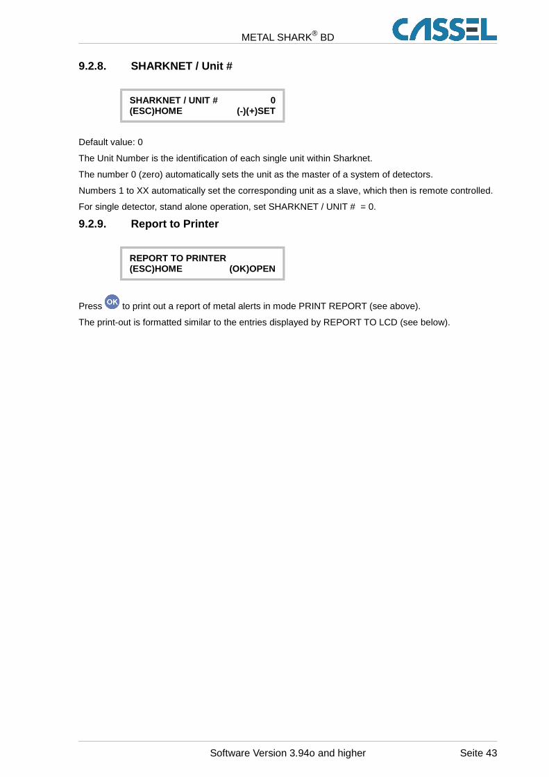
METAL SHARK® BD
9.2.8. SHARKNET / Unit #
SHARKNET / UNIT # 0(ESC)HOME (-)(+)SET
Default value: 0
The Unit Number is the identification of each single unit within Sharknet.
The number 0 (zero) automatically sets the unit as the master of a system of detectors.
Numbers 1 to XX automatically set the corresponding unit as a slave, which then is remote controlled.
For single detector, stand alone operation, set SHARKNET / UNIT # = 0.
9.2.9. Report to Printer
REPORT TO PRINTER(ESC)HOME (OK)OPEN
Press to print out a report of metal alerts in mode PRINT REPORT (see above).
The print-out is formatted similar to the entries displayed by REPORT TO LCD (see below).
Software Version 3.94o and higher Seite 43
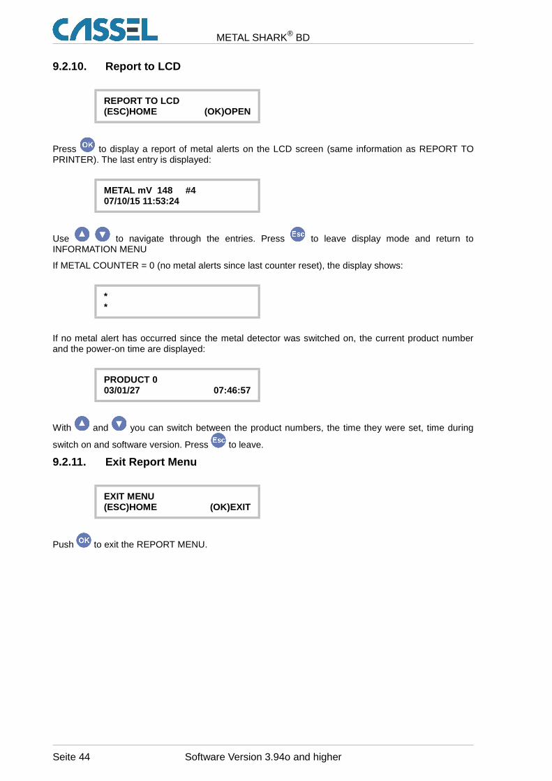
METAL SHARK® BD
9.2.10. Report to LCD
REPORT TO LCD(ESC)HOME (OK)OPEN
Press to display a report of metal alerts on the LCD screen (same information as REPORT TOPRINTER). The last entry is displayed:
METAL mV 148 #407/10/15 11:53:24
Use to navigate through the entries. Press to leave display mode and return toINFORMATION MENU
If METAL COUNTER = 0 (no metal alerts since last counter reset), the display shows:
**
If no metal alert has occurred since the metal detector was switched on, the current product numberand the power-on time are displayed:
PRODUCT 003/01/27 07:46:57
With and you can switch between the product numbers, the time they were set, time during
switch on and software version. Press to leave.
9.2.11. Exit Report Menu
EXIT MENU(ESC)HOME (OK)EXIT
Push to exit the REPORT MENU.
Seite 44 Software Version 3.94o and higher
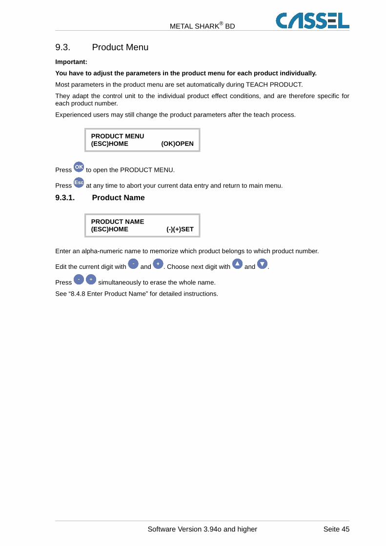
METAL SHARK® BD
9.3. Product Menu
Important:
You have to adjust the parameters in the product me nu for each product individually.
Most parameters in the product menu are set automatically during TEACH PRODUCT.
They adapt the control unit to the individual product effect conditions, and are therefore specific foreach product number.
Experienced users may still change the product parameters after the teach process.
PRODUCT MENU(ESC)HOME (OK)OPEN
Press to open the PRODUCT MENU.
Press at any time to abort your current data entry and return to main menu.
9.3.1. Product Name
PRODUCT NAME(ESC)HOME (-)(+)SET
Enter an alpha-numeric name to memorize which product belongs to which product number.
Edit the current digit with and . Choose next digit with and .
Press simultaneously to erase the whole name.
See “8.4.8 Enter Product Name” for detailed instructions.
Software Version 3.94o and higher Seite 45

METAL SHARK® BD
9.3.2. Product is ...
PRODUCT IS DRY(ESC)HOME (-)(+)SET
Choose a product characteristic which characterizes your current product. According to thischaracteristic, the product compensation will be adjusted to suit your application (see chapter “Teachproduct effects ”).
Here you can still change the product characteristic after finishing TEACH PRODUCT. The resultwould be the same as if TEACH PRODUCT had been performed with the currently set productcharacteristic. Therefore, you can try different product characteristics without repeating TEACHPRODUCT every time.
You can choose one of the following characteristics:
DRY: Products with low humidity, e.g. powder and bulk materials.
WET: Products that contain water, but not too many spices, e.g. sausages, meat, fruits, vegetables.
SALTY: Products with a high amount of salt or high electrical conductivity, e.g. cheese blocks.
MEAT: Products like bloody raw meat.
FROZEN: Deep frozen products (-18°C/0°F)
MELTING: Frozen products in warm environment
ALU FOIL: Products packed in alu vaporized foil
PLASTIC: Plastic granulates with graphite
VIBRATION: Vibration signals
SHOCK: Shock-like action on detector
DEFAULT: No product-specific adjustments are preset. Adjust PRODUCT TOL and related parametersby hand.
9.3.3. Product X TOL
PRODUCT X TOL 1.0(ESC)HOME (-)(+)SET
Setting range: 0.0 .... 9.9 Default: 1.0
Scales the product effect area along the X-axis.
PRODUCT X TOL is multiplied by PRODUCT TOL.
Refer to chapter “8.3 Product Effect Compensation: Background Information” and “9.1.3 ProductTolerance” for details.
Seite 46 Software Version 3.94o and higher
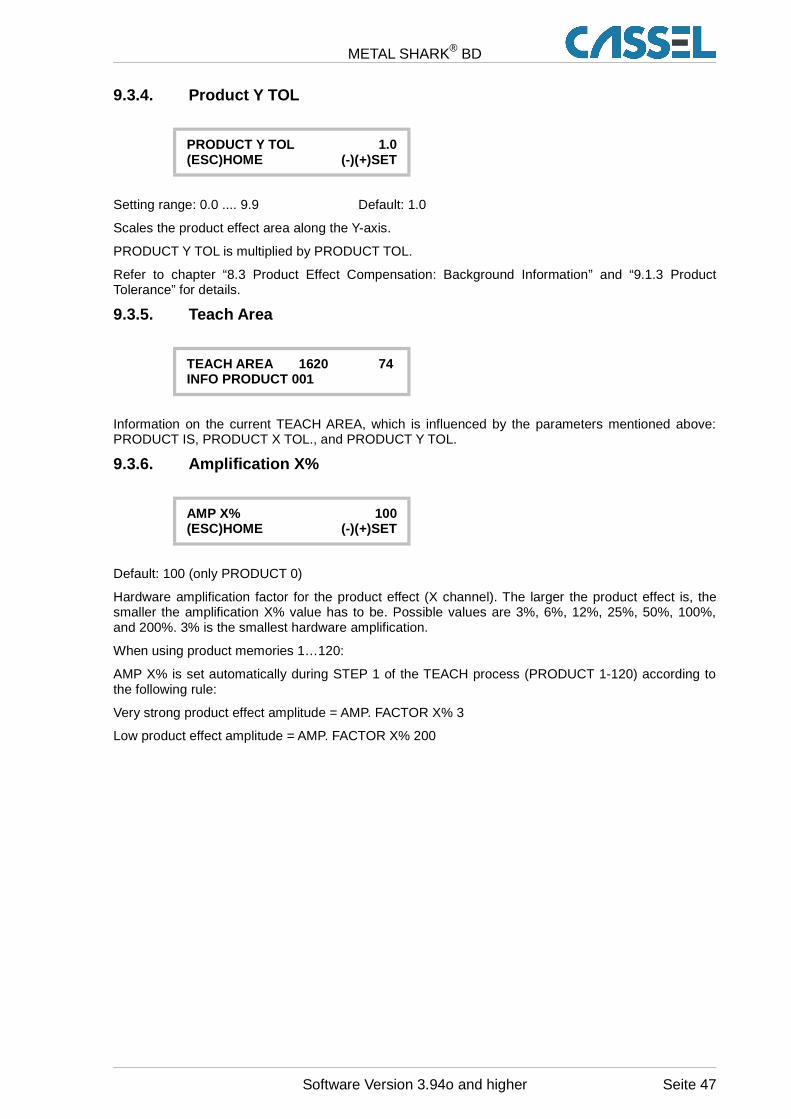
METAL SHARK® BD
9.3.4. Product Y TOL
PRODUCT Y TOL 1.0(ESC)HOME (-)(+)SET
Setting range: 0.0 .... 9.9 Default: 1.0
Scales the product effect area along the Y-axis.
PRODUCT Y TOL is multiplied by PRODUCT TOL.
Refer to chapter “8.3 Product Effect Compensation: Background Information” and “9.1.3 ProductTolerance” for details.
9.3.5. Teach Area
TEACH AREA 1620 74 INFO PRODUCT 001
Information on the current TEACH AREA, which is influenced by the parameters mentioned above:PRODUCT IS, PRODUCT X TOL., and PRODUCT Y TOL.
9.3.6. Amplification X%
AMP X% 100(ESC)HOME (-)(+)SET
Default: 100 (only PRODUCT 0)
Hardware amplification factor for the product effect (X channel). The larger the product effect is, thesmaller the amplification X% value has to be. Possible values are 3%, 6%, 12%, 25%, 50%, 100%,and 200%. 3% is the smallest hardware amplification.
When using product memories 1…120:
AMP X% is set automatically during STEP 1 of the TEACH process (PRODUCT 1-120) according tothe following rule:
Very strong product effect amplitude = AMP. FACTOR X% 3
Low product effect amplitude = AMP. FACTOR X% 200
Software Version 3.94o and higher Seite 47

METAL SHARK® BD
9.3.7. Amplification Y%
AMP Y% 100(ESC)HOME (-)(+)SET
Default: 100 (only PRODUCT 0)
Hardware amplification factor for the metal signals (Y channel). The larger the product effect crosstalkis, the smaller the amplification Y% value has to be. Possible values are 3%, 6%, 12%, 25%, 50%,100%, and 200%. 3% is the smallest hardware amplification.
When using product memories 1…120:
AMP Y% is set automatically during STEP 3 of the TEACH process (PRODUCT 1-120) according tothe following rule:
Very strong product effect crosstalk in metal channel = AMP. FACTOR Y% 3
Low product effect crosstalk in metal channel = AMP. FACTOR Y% 200
9.3.8. Phase
PHASE -179.55°(ESC)HOME (-)(+)SET
Default: 0.00°
The setting of the product phase helps to blank out any product effect. PHASE is set automaticallyduring the TEACH process.
PHASE is available with product 1…120, not with PRODUCT 000.
9.3.9. Phase Track
PHASE TRACK 0.00°(ESC)HOME (-)(+)SET
Setting range: 0.00° … 10.00° Default: 0.00°
When working with products 1-120 the product phase determined in the teach process can beadjusted during the operation to compensate slow changes of the products. The product effect phasemay change depending on product temperature and composition.
The parameter PHASETRACK indicates the increment with that the phase is adjusted:
The higher this value the stronger the phase tracking.
E.g. a 0.10° means 0.10 degree tracking with each p roduct or metal signal.
Seite 48 Software Version 3.94o and higher
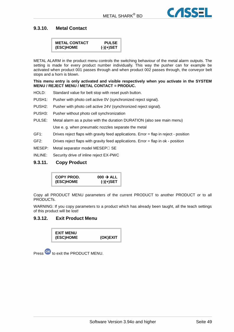
METAL SHARK® BD
9.3.10. Metal Contact
METAL CONTACT PULSE(ESC)HOME (-)(+)SET
METAL ALARM in the product menu controls the switching behaviour of the metal alarm outputs. Thesetting is made for every product number individually. This way the pusher can for example beactivated when product 001 passes through and when product 002 passes through, the conveyor beltstops and a horn is blown.
This menu entry is only activated and visible respe ctively when you activate in the SYSTEMMENU / REJECT MENU / METAL CONTACT = PRODUC.
HOLD: Standard value for belt stop with reset push button.
PUSH1: Pusher with photo cell active 0V (synchronized reject signal).
PUSH2: Pusher with photo cell active 24V (synchronized reject signal).
PUSH3: Pusher without photo cell synchronization
PULSE: Metal alarm as a pulse with the duration DURATION (also see main menu)
Use e. g. when pneumatic nozzles separate the metal
GF1: Drives reject flaps with gravity feed applications. Error = flap in reject - position
GF2: Drives reject flaps with gravity feed applications. Error = flap in ok - position
MESEP: Metal separator model MESEP SE
INLINE: Security drive of inline reject EX-PWC
9.3.11. Copy Product
COPY PROD. 000 ���� ALL(ESC)HOME (-)(+)SET
Copy all PRODUCT MENU parameters of the current PRODUCT to another PRODUCT or to allPRODUCTs.
WARNING: If you copy parameters to a product which has already been taught, all the teach settingsof this product will be lost!
9.3.12. Exit Product Menu
EXIT MENU(ESC)HOME (OK)EXIT
Press to exit the PRODUCT MENU.
Software Version 3.94o and higher Seite 49
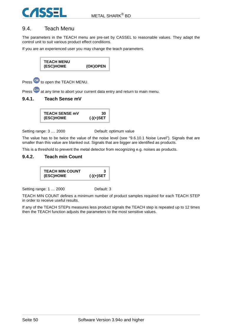
METAL SHARK® BD
9.4. Teach Menu
The parameters in the TEACH menu are pre-set by CASSEL to reasonable values. They adapt thecontrol unit to suit various product effect conditions.
If you are an experienced user you may change the teach parameters.
TEACH MENU(ESC)HOME (OK)OPEN
Press to open the TEACH MENU.
Press at any time to abort your current data entry and return to main menu.
9.4.1. Teach Sense mV
TEACH SENSE mV 30(ESC)HOME (-)(+)SET
Setting range: 3 .... 2000 Default: optimum value
The value has to be twice the value of the noise level (see “9.6.10.1 Noise Level”). Signals that aresmaller than this value are blanked out. Signals that are bigger are identified as products.
This is a threshold to prevent the metal detector from recognizing e.g. noises as products.
9.4.2. Teach min Count
TEACH MIN COUNT 3(ESC)HOME (-)(+)SET
Setting range: 1 … 2000 Default: 3
TEACH MIN COUNT defines a minimum number of product samples required for each TEACH STEPin order to receive useful results.
If any of the TEACH STEPs measures less product signals the TEACH step is repeated up to 12 timesthen the TEACH function adjusts the parameters to the most sensitive values.
Seite 50 Software Version 3.94o and higher
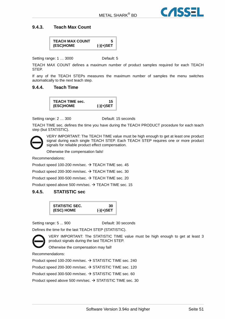
METAL SHARK® BD
9.4.3. Teach Max Count
TEACH MAX COUNT 5(ESC)HOME (-)(+)SET
Setting range: 1 … 3000 Default: 5
TEACH MAX COUNT defines a maximum number of product samples required for each TEACHSTEP.
If any of the TEACH STEPs measures the maximum number of samples the menu switchesautomatically to the next teach step.
9.4.4. Teach Time
TEACH TIME sec. 15(ESC)HOME (-)(+)SET
Setting range: 2 … 300 Default: 15 seconds
TEACH TIME sec. defines the time you have during the TEACH PRODUCT procedure for each teachstep (but STATISTIC).
VERY IMPORTANT: The TEACH TIME value must be high enough to get at least one productsignal during each single TEACH STEP. Each TEACH STEP requires one or more productsignals for reliable product effect compensation.
Otherwise the compensation fails!
Recommendations:
Product speed 100-200 mm/sec. � TEACH TIME sec. 45
Product speed 200-300 mm/sec. � TEACH TIME sec. 30
Product speed 300-500 mm/sec. � TEACH TIME sec. 20
Product speed above 500 mm/sec. � TEACH TIME sec. 15
9.4.5. STATISTIC sec
STATISTIC SEC. 30(ESC) HOME (-)(+)SET
Setting range: 5 ... 900 Default: 30 seconds
Defines the time for the last TEACH STEP (STATISTIC).
VERY IMPORTANT: The STATISTIC TIME value must be high enough to get at least 3product signals during the last TEACH STEP.
Otherwise the compensation may fail!
Recommendations:
Product speed 100-200 mm/sec. � STATISTIC TIME sec. 240
Product speed 200-300 mm/sec. � STATISTIC TIME sec. 120
Product speed 300-500 mm/sec. � STATISTIC TIME sec. 60
Product speed above 500 mm/sec. � STATISTIC TIME sec. 30
Software Version 3.94o and higher Seite 51
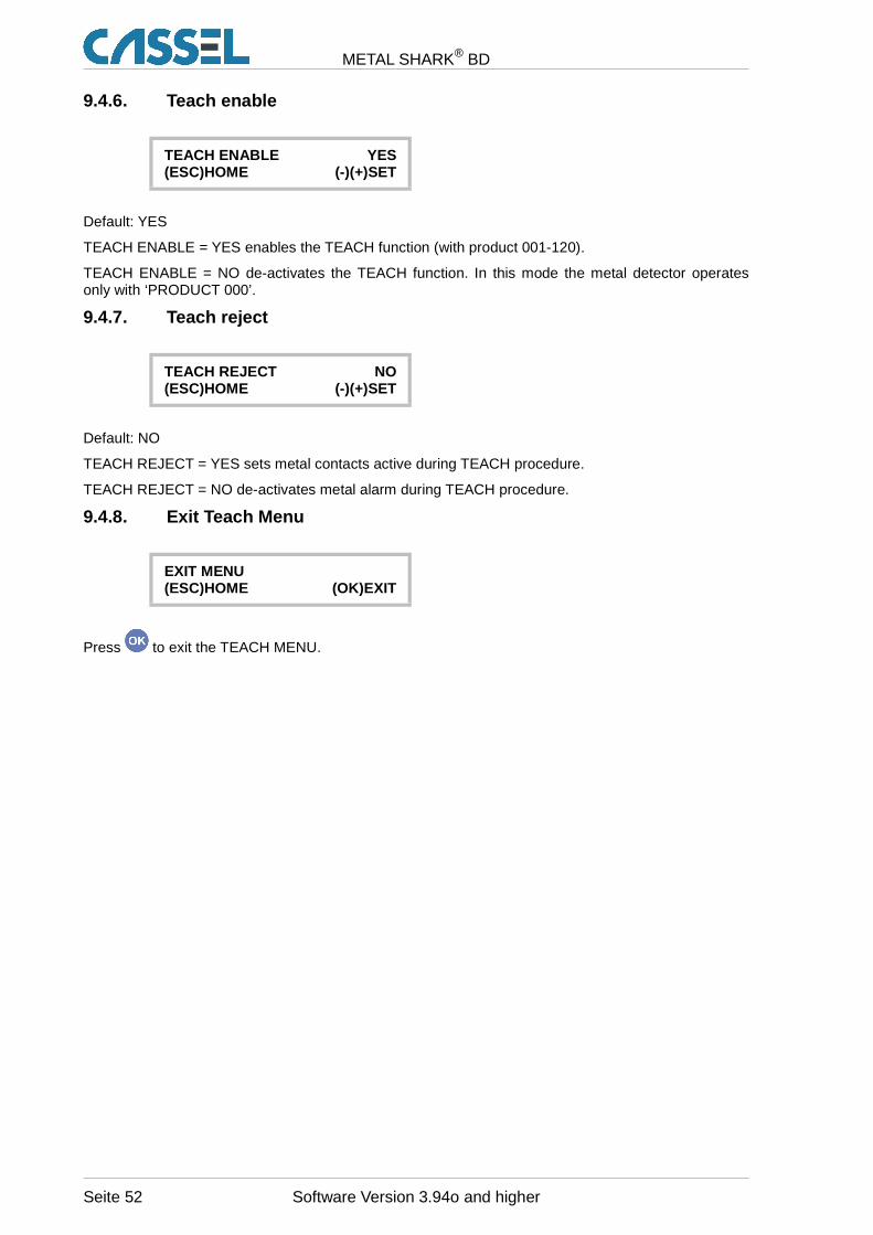
METAL SHARK® BD
9.4.6. Teach enable
TEACH ENABLE YES(ESC)HOME (-)(+)SET
Default: YES
TEACH ENABLE = YES enables the TEACH function (with product 001-120).
TEACH ENABLE = NO de-activates the TEACH function. In this mode the metal detector operatesonly with ‘PRODUCT 000’.
9.4.7. Teach reject
TEACH REJECT NO(ESC)HOME (-)(+)SET
Default: NO
TEACH REJECT = YES sets metal contacts active during TEACH procedure.
TEACH REJECT = NO de-activates metal alarm during TEACH procedure.
9.4.8. Exit Teach Menu
EXIT MENU(ESC)HOME (OK)EXIT
Press to exit the TEACH MENU.
Seite 52 Software Version 3.94o and higher
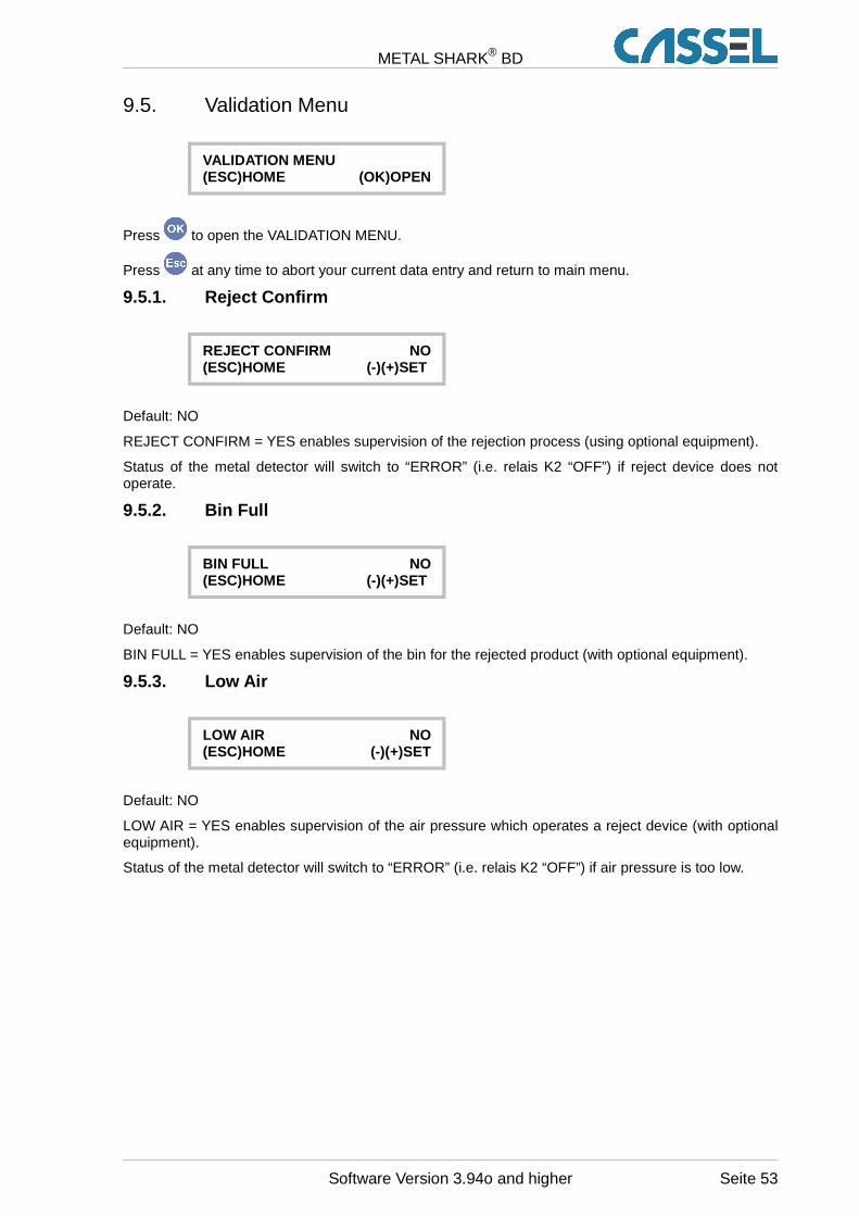
METAL SHARK® BD
9.5. Validation Menu
VALIDATION MENU(ESC)HOME (OK)OPEN
Press to open the VALIDATION MENU.
Press at any time to abort your current data entry and return to main menu.
9.5.1. Reject Confirm
REJECT CONFIRM NO(ESC)HOME (-)(+)SET
Default: NO
REJECT CONFIRM = YES enables supervision of the rejection process (using optional equipment).
Status of the metal detector will switch to “ERROR” (i.e. relais K2 “OFF”) if reject device does notoperate.
9.5.2. Bin Full
BIN FULL NO(ESC)HOME (-)(+)SET
Default: NO
BIN FULL = YES enables supervision of the bin for the rejected product (with optional equipment).
9.5.3. Low Air
LOW AIR NO(ESC)HOME (-)(+)SET
Default: NO
LOW AIR = YES enables supervision of the air pressure which operates a reject device (with optionalequipment).
Status of the metal detector will switch to “ERROR” (i.e. relais K2 “OFF”) if air pressure is too low.
Software Version 3.94o and higher Seite 53
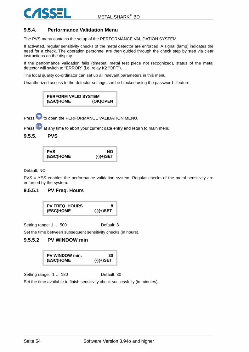
METAL SHARK® BD
9.5.4. Performance Validation Menu
The PVS menu contains the setup of the PERFORMANCE VALIDATION SYSTEM.
If activated, regular sensitivity checks of the metal detector are enforced. A signal (lamp) indicates theneed for a check. The operation personnel are then guided through the check step by step via clearinstructions on the display.
If the performance validation fails (timeout, metal test piece not recognized), status of the metaldetector will switch to “ERROR” (i.e. relay K2 “OFF”).
The local quality co-ordinator can set up all relevant parameters in this menu.
Unauthorized access to the detector settings can be blocked using the password –feature.
PERFORM VALID SYSTEM(ESC)HOME (OK)OPEN
Press to open the PERFORMANCE VALIDATION MENU.
Press at any time to abort your current data entry and return to main menu.
9.5.5. PVS
PVS NO(ESC)HOME (-)(+)SET
Default: NO
PVS = YES enables the performance validation system. Regular checks of the metal sensitivity areenforced by the system.
9.5.5.1 PV Freq. Hours
PV FREQ. HOURS 8(ESC)HOME (-)(+)SET
Setting range: 1 … 500 Default: 8
Set the time between subsequent sensitivity checks (in hours).
9.5.5.2 PV WINDOW min
PV WINDOW min. 30(ESC)HOME (-)(+)SET
Setting range: 1 … 180 Default: 30
Set the time available to finish sensitivity check successfully (in minutes).
Seite 54 Software Version 3.94o and higher
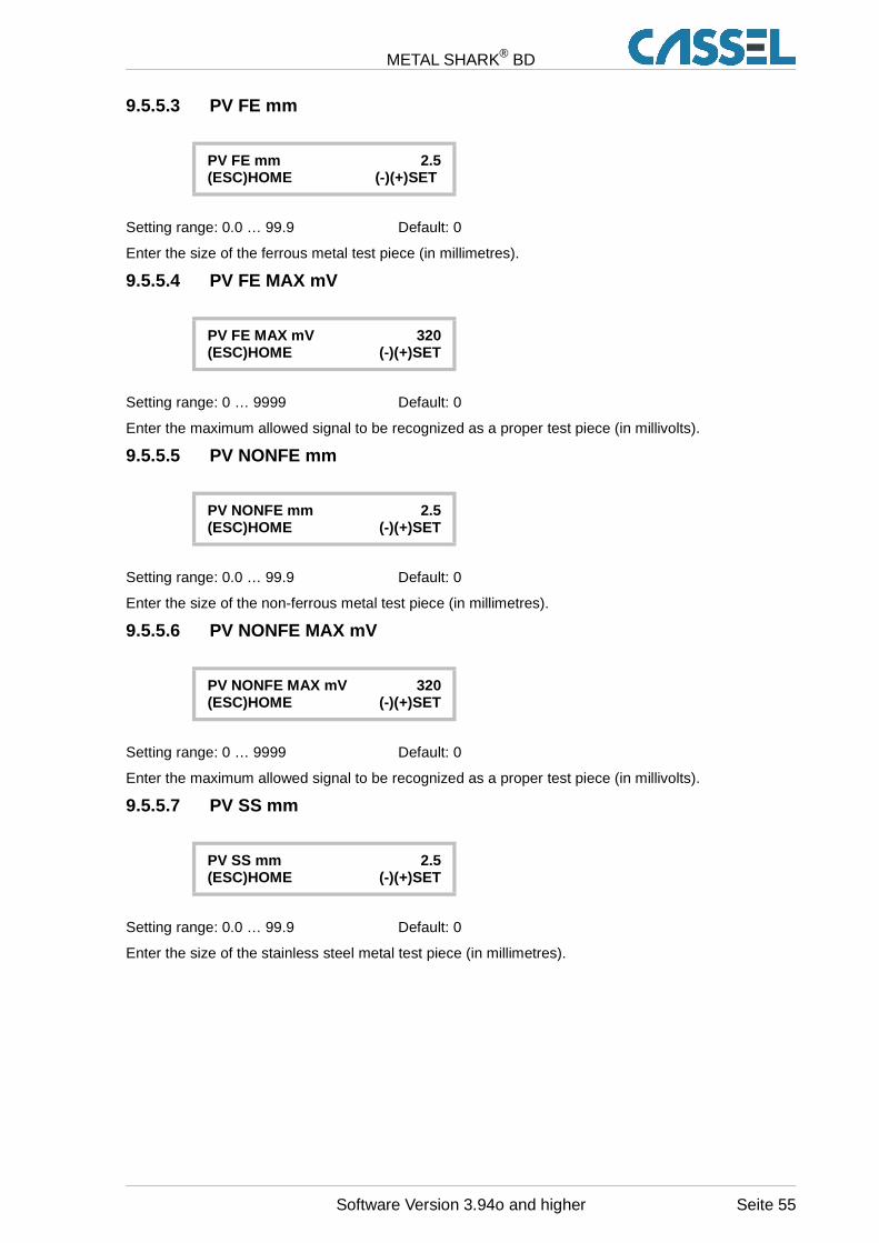
METAL SHARK® BD
9.5.5.3 PV FE mm
PV FE mm 2.5(ESC)HOME (-)(+)SET
Setting range: 0.0 … 99.9 Default: 0
Enter the size of the ferrous metal test piece (in millimetres).
9.5.5.4 PV FE MAX mV
PV FE MAX mV 320(ESC)HOME (-)(+)SET
Setting range: 0 … 9999 Default: 0
Enter the maximum allowed signal to be recognized as a proper test piece (in millivolts).
9.5.5.5 PV NONFE mm
PV NONFE mm 2.5(ESC)HOME (-)(+)SET
Setting range: 0.0 … 99.9 Default: 0
Enter the size of the non-ferrous metal test piece (in millimetres).
9.5.5.6 PV NONFE MAX mV
PV NONFE MAX mV 320(ESC)HOME (-)(+)SET
Setting range: 0 … 9999 Default: 0
Enter the maximum allowed signal to be recognized as a proper test piece (in millivolts).
9.5.5.7 PV SS mm
PV SS mm 2.5(ESC)HOME (-)(+)SET
Setting range: 0.0 … 99.9 Default: 0
Enter the size of the stainless steel metal test piece (in millimetres).
Software Version 3.94o and higher Seite 55
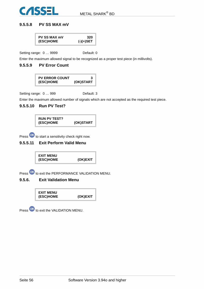
METAL SHARK® BD
9.5.5.8 PV SS MAX mV
PV SS MAX mV 320(ESC)HOME (-)(+)SET
Setting range: 0 … 9999 Default: 0
Enter the maximum allowed signal to be recognized as a proper test piece (in millivolts).
9.5.5.9 PV Error Count
PV ERROR COUNT 3(ESC)HOME (OK)START
Setting range: 0 … 999 Default: 3
Enter the maximum allowed number of signals which are not accepted as the required test piece.
9.5.5.10 Run PV Test?
RUN PV TEST?(ESC)HOME (OK)START
Press to start a sensitivity check right now.
9.5.5.11 Exit Perform Valid Menu
EXIT MENU(ESC)HOME (OK)EXIT
Press to exit the PERFORMANCE VALIDATION MENU.
9.5.6. Exit Validation Menu
EXIT MENU(ESC)HOME (OK)EXIT
Press to exit the VALIDATION MENU.
Seite 56 Software Version 3.94o and higher
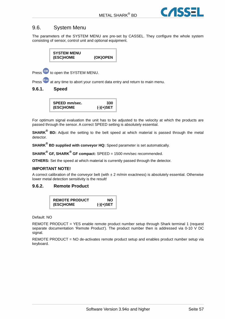
METAL SHARK® BD
9.6. System Menu
The parameters of the SYSTEM MENU are pre-set by CASSEL. They configure the whole systemconsisting of sensor, control unit and optional equipment.
SYSTEM MENU(ESC)HOME (OK)OPEN
Press to open the SYSTEM MENU.
Press at any time to abort your current data entry and return to main menu.
9.6.1. Speed
SPEED mm/sec. 330(ESC)HOME (-)(+)SET
For optimum signal evaluation the unit has to be adjusted to the velocity at which the products arepassed through the sensor. A correct SPEED setting is absolutely essential.
SHARK® BD: Adjust the setting to the belt speed at which material is passed through the metaldetector.
SHARK® BD supplied with conveyor HQ: Speed parameter is set automatically.
SHARK® GF, SHARK ® GF compact: SPEED = 1500 mm/sec recommended.
OTHERS: Set the speed at which material is currently passed through the detector.
IMPORTANT NOTE!A correct calibration of the conveyor belt (with ± 2 m/min exactness) is absolutely essential. Otherwiselower metal detection sensitivity is the result!
9.6.2. Remote Product
REMOTE PRODUCT NO(ESC)HOME (-)(+)SET
Default: NO
REMOTE PRODUCT = YES enable remote product number setup through Shark terminal 1 (requestseparate documentation ‘Remote Product’). The product number then is addressed via 0-10 V DCsignal.
REMOTE PRODUCT = NO de-activates remote product setup and enables product number setup viakeyboard.
Software Version 3.94o and higher Seite 57
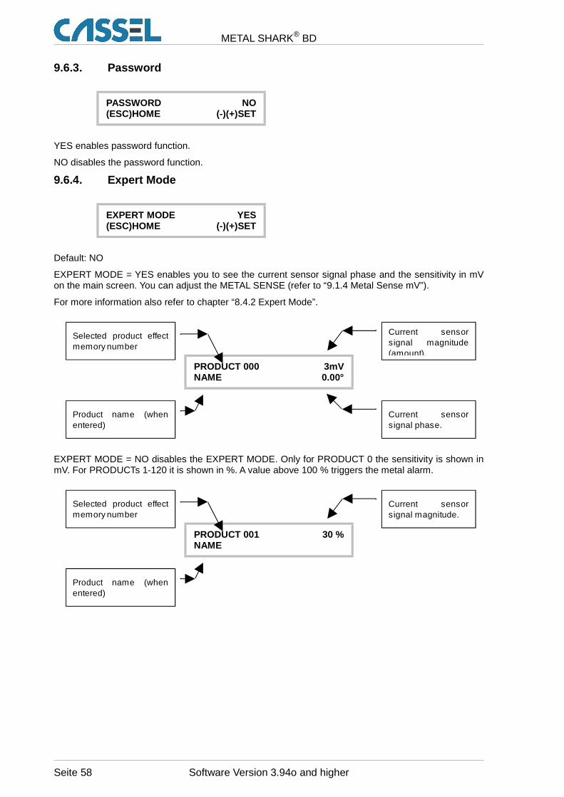
METAL SHARK® BD
9.6.3. Password
PASSWORD NO(ESC)HOME (-)(+)SET
YES enables password function.
NO disables the password function.
9.6.4. Expert Mode
EXPERT MODE YES(ESC)HOME (-)(+)SET
Default: NO
EXPERT MODE = YES enables you to see the current sensor signal phase and the sensitivity in mVon the main screen. You can adjust the METAL SENSE (refer to “9.1.4 Metal Sense mV”).
For more information also refer to chapter “8.4.2 Expert Mode”.
PRODUCT 000 3mVNAME 0.00°
EXPERT MODE = NO disables the EXPERT MODE. Only for PRODUCT 0 the sensitivity is shown inmV. For PRODUCTs 1-120 it is shown in %. A value above 100 % triggers the metal alarm.
PRODUCT 001 30 %NAME
Seite 58 Software Version 3.94o and higher
Selected product effect memory number
Current sensor signal magnitude (amount).
Current sensor signal phase.
Product name (when entered)
Selected product effect memory number
Current sensor signal magnitude.
Product name (when entered)
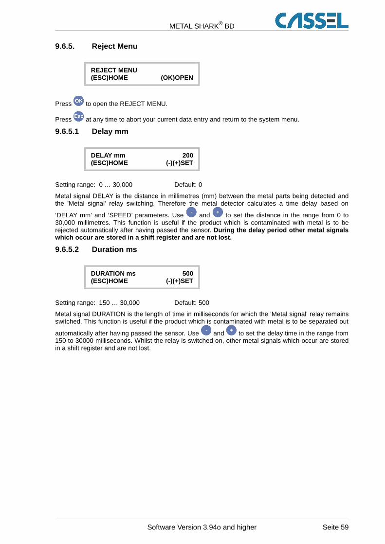
METAL SHARK® BD
9.6.5. Reject Menu
REJECT MENU(ESC)HOME (OK)OPEN
Press to open the REJECT MENU.
Press at any time to abort your current data entry and return to the system menu.
9.6.5.1 Delay mm
DELAY mm 200(ESC)HOME (-)(+)SET
Setting range: 0 … 30,000 Default: 0
Metal signal DELAY is the distance in millimetres (mm) between the metal parts being detected andthe 'Metal signal' relay switching. Therefore the metal detector calculates a time delay based on
‘DELAY mm’ and ‘SPEED’ parameters. Use and to set the distance in the range from 0 to30,000 millimetres. This function is useful if the product which is contaminated with metal is to berejected automatically after having passed the sensor. During the delay period other metal signalswhich occur are stored in a shift register and are not lost.
9.6.5.2 Duration ms
DURATION ms 500(ESC)HOME (-)(+)SET
Setting range: 150 … 30,000 Default: 500
Metal signal DURATION is the length of time in milliseconds for which the 'Metal signal' relay remainsswitched. This function is useful if the product which is contaminated with metal is to be separated out
automatically after having passed the sensor. Use and to set the delay time in the range from150 to 30000 milliseconds. Whilst the relay is switched on, other metal signals which occur are storedin a shift register and are not lost.
Software Version 3.94o and higher Seite 59
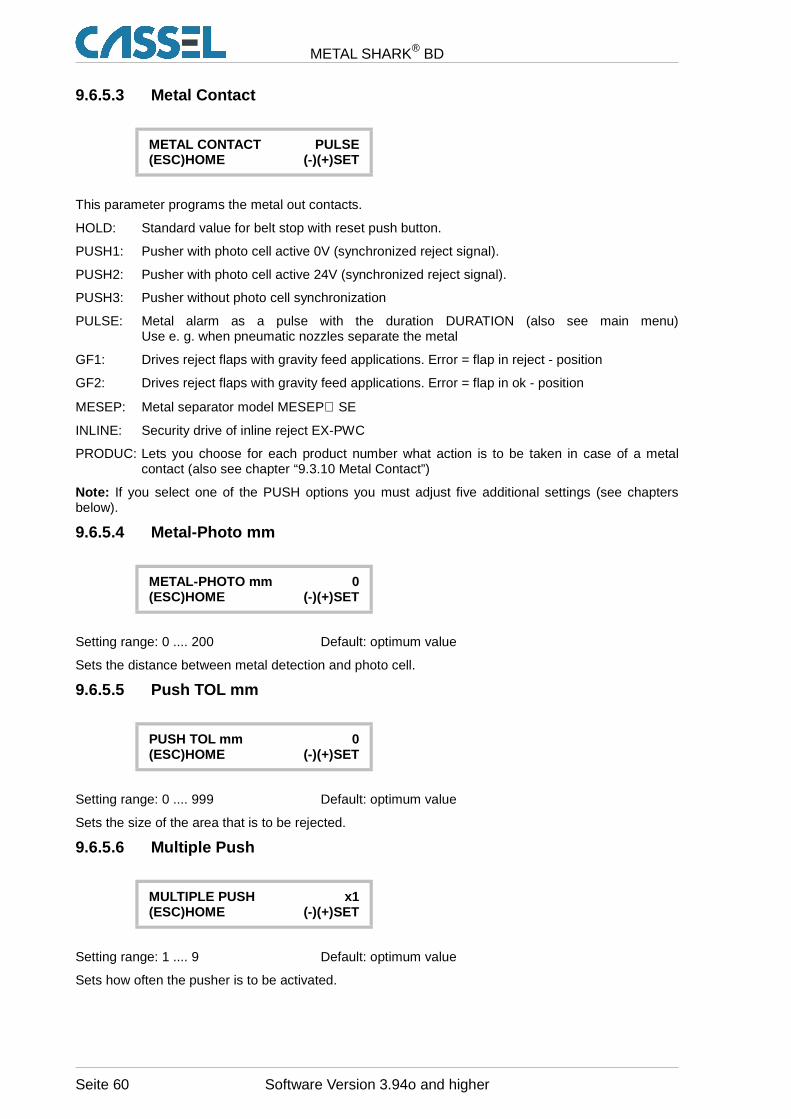
METAL SHARK® BD
9.6.5.3 Metal Contact
METAL CONTACT PULSE(ESC)HOME (-)(+)SET
This parameter programs the metal out contacts.
HOLD: Standard value for belt stop with reset push button.
PUSH1: Pusher with photo cell active 0V (synchronized reject signal).
PUSH2: Pusher with photo cell active 24V (synchronized reject signal).
PUSH3: Pusher without photo cell synchronization
PULSE: Metal alarm as a pulse with the duration DURATION (also see main menu)Use e. g. when pneumatic nozzles separate the metal
GF1: Drives reject flaps with gravity feed applications. Error = flap in reject - position
GF2: Drives reject flaps with gravity feed applications. Error = flap in ok - position
MESEP: Metal separator model MESEP SE
INLINE: Security drive of inline reject EX-PWC
PRODUC: Lets you choose for each product number what action is to be taken in case of a metalcontact (also see chapter “9.3.10 Metal Contact”)
Note: If you select one of the PUSH options you must adjust five additional settings (see chaptersbelow).
9.6.5.4 Metal-Photo mm
METAL-PHOTO mm 0(ESC)HOME (-)(+)SET
Setting range: 0 .... 200 Default: optimum value
Sets the distance between metal detection and photo cell.
9.6.5.5 Push TOL mm
PUSH TOL mm 0(ESC)HOME (-)(+)SET
Setting range: 0 .... 999 Default: optimum value
Sets the size of the area that is to be rejected.
9.6.5.6 Multiple Push
MULTIPLE PUSH x1(ESC)HOME (-)(+)SET
Setting range: 1 .... 9 Default: optimum value
Sets how often the pusher is to be activated.
Seite 60 Software Version 3.94o and higher
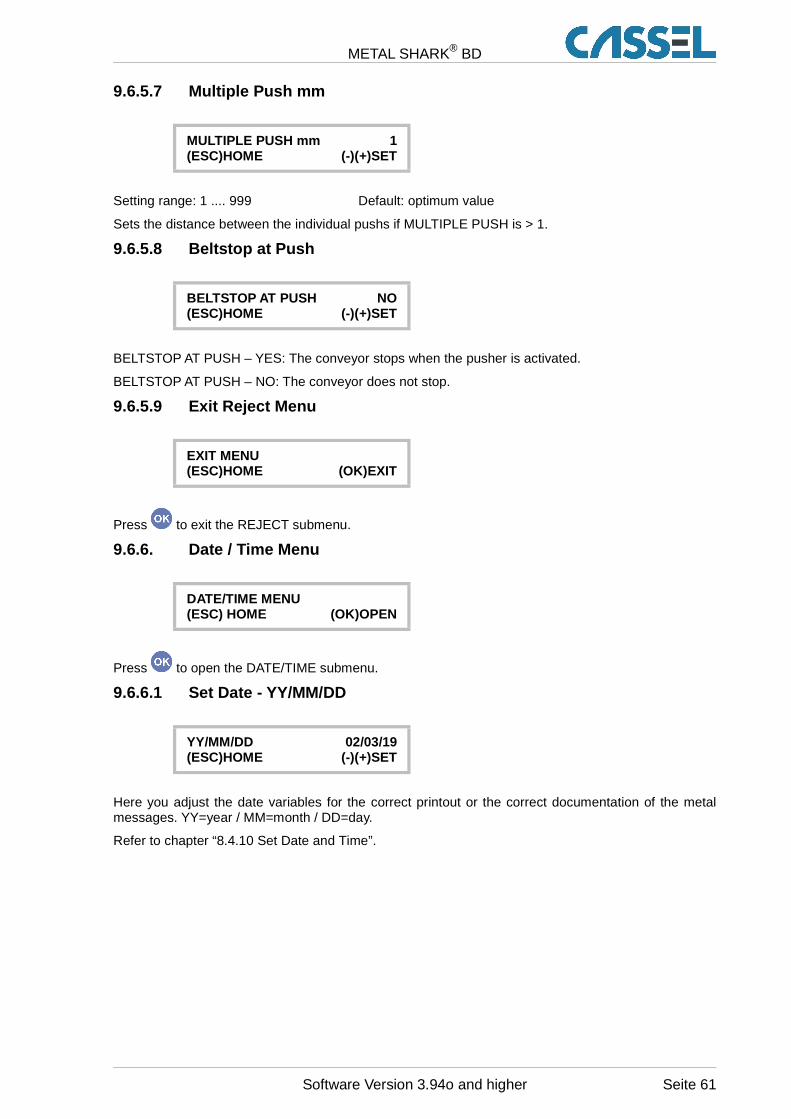
METAL SHARK® BD
9.6.5.7 Multiple Push mm
MULTIPLE PUSH mm 1(ESC)HOME (-)(+)SET
Setting range: 1 .... 999 Default: optimum value
Sets the distance between the individual pushs if MULTIPLE PUSH is > 1.
9.6.5.8 Beltstop at Push
BELTSTOP AT PUSH NO(ESC)HOME (-)(+)SET
BELTSTOP AT PUSH – YES: The conveyor stops when the pusher is activated.
BELTSTOP AT PUSH – NO: The conveyor does not stop.
9.6.5.9 Exit Reject Menu
EXIT MENU(ESC)HOME (OK)EXIT
Press to exit the REJECT submenu.
9.6.6. Date / Time Menu
DATE/TIME MENU(ESC) HOME (OK)OPEN
Press to open the DATE/TIME submenu.
9.6.6.1 Set Date - YY/MM/DD
YY/MM/DD 02/03/19(ESC)HOME (-)(+)SET
Here you adjust the date variables for the correct printout or the correct documentation of the metalmessages. YY=year / MM=month / DD=day.
Refer to chapter “8.4.10 Set Date and Time”.
Software Version 3.94o and higher Seite 61
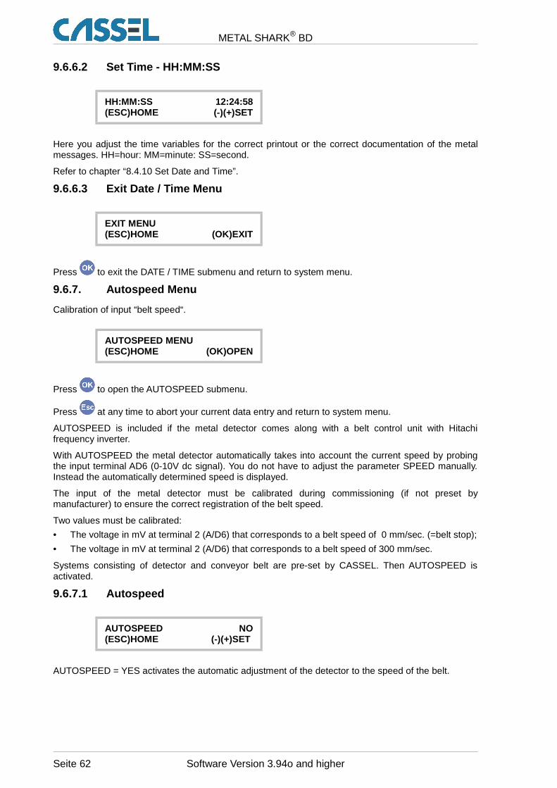
METAL SHARK® BD
9.6.6.2 Set Time - HH:MM:SS
HH:MM:SS 12:24:58(ESC)HOME (-)(+)SET
Here you adjust the time variables for the correct printout or the correct documentation of the metalmessages. HH=hour: MM=minute: SS=second.
Refer to chapter “8.4.10 Set Date and Time”.
9.6.6.3 Exit Date / Time Menu
EXIT MENU(ESC)HOME (OK)EXIT
Press to exit the DATE / TIME submenu and return to system menu.
9.6.7. Autospeed Menu
Calibration of input “belt speed“.
AUTOSPEED MENU(ESC)HOME (OK)OPEN
Press to open the AUTOSPEED submenu.
Press at any time to abort your current data entry and return to system menu.
AUTOSPEED is included if the metal detector comes along with a belt control unit with Hitachifrequency inverter.
With AUTOSPEED the metal detector automatically takes into account the current speed by probingthe input terminal AD6 (0-10V dc signal). You do not have to adjust the parameter SPEED manually.Instead the automatically determined speed is displayed.
The input of the metal detector must be calibrated during commissioning (if not preset bymanufacturer) to ensure the correct registration of the belt speed.
Two values must be calibrated:
• The voltage in mV at terminal 2 (A/D6) that corresponds to a belt speed of 0 mm/sec. (=belt stop);
• The voltage in mV at terminal 2 (A/D6) that corresponds to a belt speed of 300 mm/sec.
Systems consisting of detector and conveyor belt are pre-set by CASSEL. Then AUTOSPEED isactivated.
9.6.7.1 Autospeed
AUTOSPEED NO(ESC)HOME (-)(+)SET
AUTOSPEED = YES activates the automatic adjustment of the detector to the speed of the belt.
Seite 62 Software Version 3.94o and higher
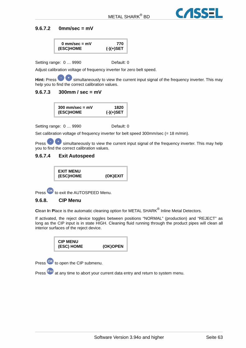
METAL SHARK® BD
9.6.7.2 0mm/sec = mV
0 mm/sec = mV 770(ESC)HOME (-)(+)SET
Setting range: 0 … 9990 Default: 0
Adjust calibration voltage of frequency inverter for zero belt speed.
Hint: Press simultaneously to view the current input signal of the frequency inverter. This mayhelp you to find the correct calibration values.
9.6.7.3 300mm / sec = mV
300 mm/sec = mV 1820(ESC)HOME (-)(+)SET
Setting range: 0 … 9990 Default: 0
Set calibration voltage of frequency inverter for belt speed 300mm/sec (= 18 m/min).
Press simultaneously to view the current input signal of the frequency inverter. This may helpyou to find the correct calibration values.
9.6.7.4 Exit Autospeed
EXIT MENU(ESC)HOME (OK)EXIT
Press to exit the AUTOSPEED Menu.
9.6.8. CIP Menu
Clean In Place is the automatic cleaning option for METAL SHARK® Inline Metal Detectors.
If activated, the reject device toggles between positions “NORMAL” (production) and “REJECT” aslong as the CIP input is in state HIGH. Cleaning fluid running through the product pipes will clean allinterior surfaces of the reject device.
CIP MENU(ESC) HOME (OK)OPEN
Press to open the CIP submenu.
Press at any time to abort your current data entry and return to system menu.
Software Version 3.94o and higher Seite 63
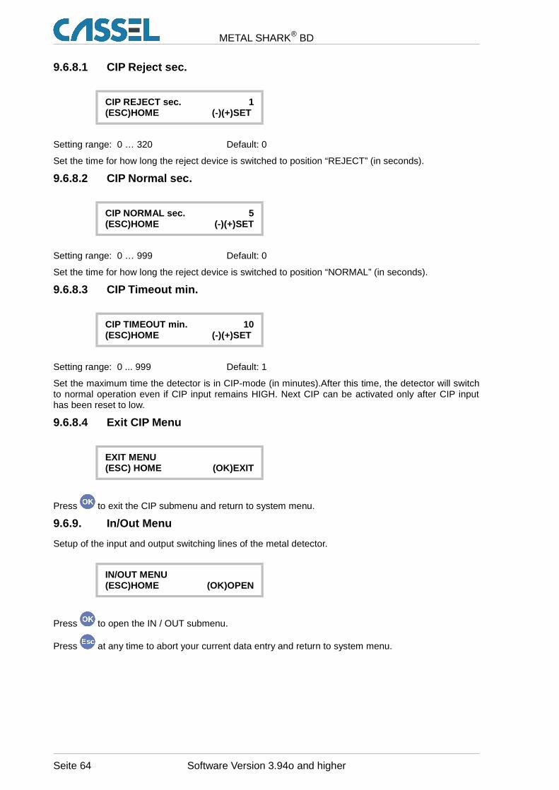
METAL SHARK® BD
9.6.8.1 CIP Reject sec.
CIP REJECT sec. 1(ESC)HOME (-)(+)SET
Setting range: 0 … 320 Default: 0
Set the time for how long the reject device is switched to position “REJECT” (in seconds).
9.6.8.2 CIP Normal sec.
CIP NORMAL sec. 5(ESC)HOME (-)(+)SET
Setting range: 0 … 999 Default: 0
Set the time for how long the reject device is switched to position “NORMAL” (in seconds).
9.6.8.3 CIP Timeout min.
CIP TIMEOUT min. 10(ESC)HOME (-)(+)SET
Setting range: 0 ... 999 Default: 1
Set the maximum time the detector is in CIP-mode (in minutes).After this time, the detector will switchto normal operation even if CIP input remains HIGH. Next CIP can be activated only after CIP inputhas been reset to low.
9.6.8.4 Exit CIP Menu
EXIT MENU(ESC) HOME (OK)EXIT
Press to exit the CIP submenu and return to system menu.
9.6.9. In/Out Menu
Setup of the input and output switching lines of the metal detector.
IN/OUT MENU(ESC)HOME (OK)OPEN
Press to open the IN / OUT submenu.
Press at any time to abort your current data entry and return to system menu.
Seite 64 Software Version 3.94o and higher
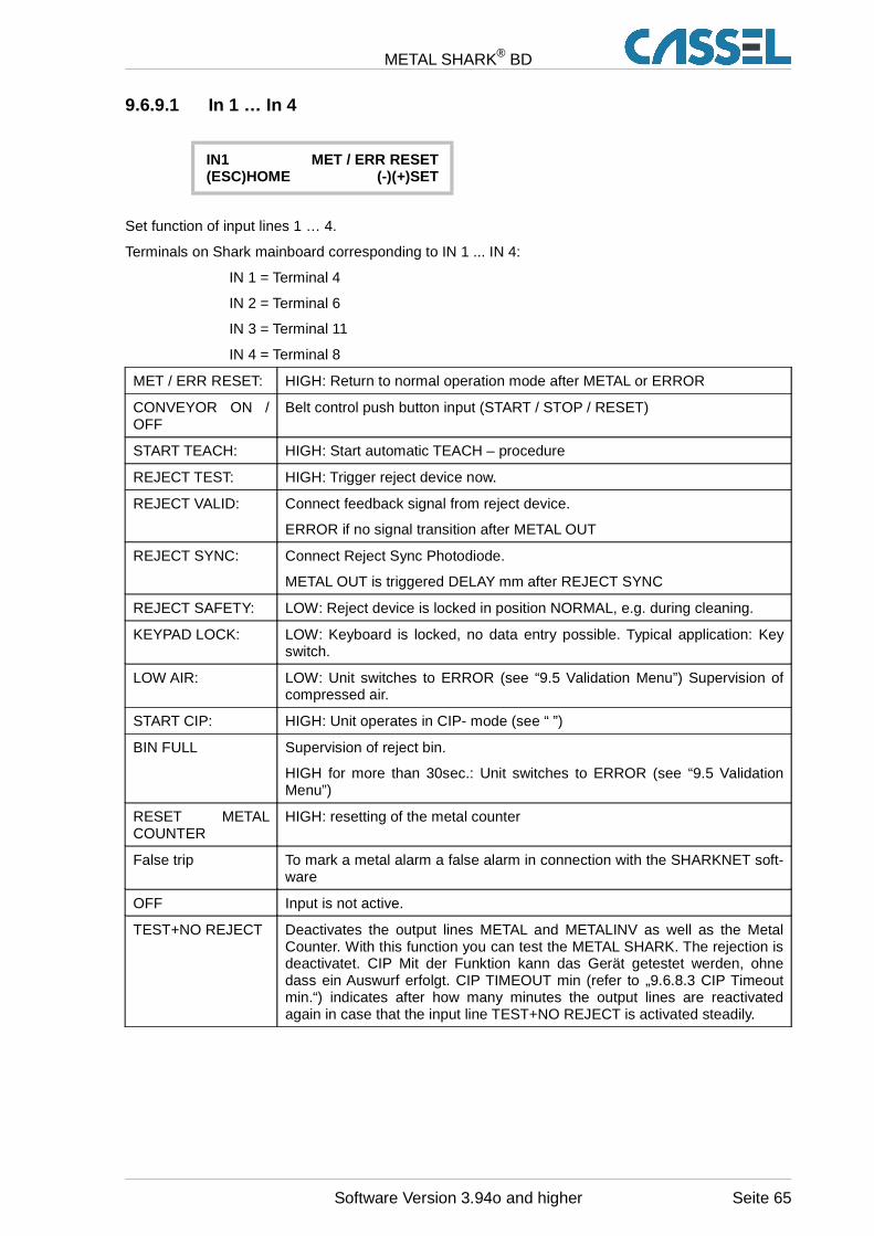
METAL SHARK® BD
9.6.9.1 In 1 … In 4
IN1 MET / ERR RESET(ESC)HOME (-)(+)SET
Set function of input lines 1 … 4.
Terminals on Shark mainboard corresponding to IN 1 ... IN 4:
IN 1 = Terminal 4
IN 2 = Terminal 6
IN 3 = Terminal 11
IN 4 = Terminal 8
MET / ERR RESET: HIGH: Return to normal operation mode after METAL or ERROR
CONVEYOR ON /OFF
Belt control push button input (START / STOP / RESET)
START TEACH: HIGH: Start automatic TEACH – procedure
REJECT TEST: HIGH: Trigger reject device now.
REJECT VALID: Connect feedback signal from reject device.
ERROR if no signal transition after METAL OUT
REJECT SYNC: Connect Reject Sync Photodiode.
METAL OUT is triggered DELAY mm after REJECT SYNC
REJECT SAFETY: LOW: Reject device is locked in position NORMAL, e.g. during cleaning.
KEYPAD LOCK: LOW: Keyboard is locked, no data entry possible. Typical application: Keyswitch.
LOW AIR: LOW: Unit switches to ERROR (see “9.5 Validation Menu”) Supervision ofcompressed air.
START CIP: HIGH: Unit operates in CIP- mode (see “ ”)
BIN FULL Supervision of reject bin.
HIGH for more than 30sec.: Unit switches to ERROR (see “9.5 ValidationMenu”)
RESET METALCOUNTER
HIGH: resetting of the metal counter
False trip To mark a metal alarm a false alarm in connection with the SHARKNET soft-ware
OFF Input is not active.
TEST+NO REJECT Deactivates the output lines METAL and METALINV as well as the MetalCounter. With this function you can test the METAL SHARK. The rejection isdeactivatet. CIP Mit der Funktion kann das Gerät getestet werden, ohnedass ein Auswurf erfolgt. CIP TIMEOUT min (refer to „9.6.8.3 CIP Timeoutmin.“) indicates after how many minutes the output lines are reactivatedagain in case that the input line TEST+NO REJECT is activated steadily.
Software Version 3.94o and higher Seite 65
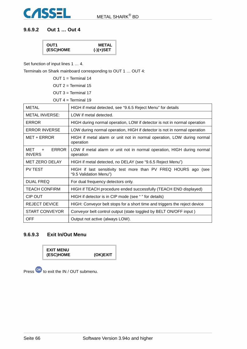
METAL SHARK® BD
9.6.9.2 Out 1 … Out 4
OUT1 METAL(ESC)HOME (-)(+)SET
Set function of input lines 1 … 4.
Terminals on Shark mainboard corresponding to OUT 1 … OUT 4:
OUT 1 = Terminal 14
OUT 2 = Terminal 15
OUT 3 = Terminal 17
OUT 4 = Terminal 19
METAL HIGH if metal detected, see “9.6.5 Reject Menu” for details
METAL INVERSE: LOW if metal detected.
ERROR HIGH during normal operation, LOW if detector is not in normal operation
ERROR INVERSE LOW during normal operation, HIGH if detector is not in normal operation
MET + ERROR HIGH if metal alarm or unit not in normal operation, LOW during normaloperation
MET + ERRORINVERS
LOW if metal alarm or unit not in normal operation, HIGH during normaloperation
MET ZERO DELAY HIGH if metal detected, no DELAY (see “9.6.5 Reject Menu”)
PV TEST HIGH if last sensitivity test more than PV FREQ HOURS ago (see“9.5 Validation Menu”)
DUAL FREQ For dual frequency detectors only.
TEACH CONFIRM HIGH if TEACH procedure ended successfully (TEACH END displayed)
CIP OUT HIGH if detector is in CIP mode (see “ ” for details)
REJECT DEVICE HIGH: Conveyor belt stops for a short time and triggers the reject device
START CONVEYOR Conveyor belt control output (state toggled by BELT ON/OFF input )
OFF Output not active (always LOW).
9.6.9.3 Exit In/Out Menu
EXIT MENU(ESC)HOME (OK)EXIT
Press to exit the IN / OUT submenu.
Seite 66 Software Version 3.94o and higher
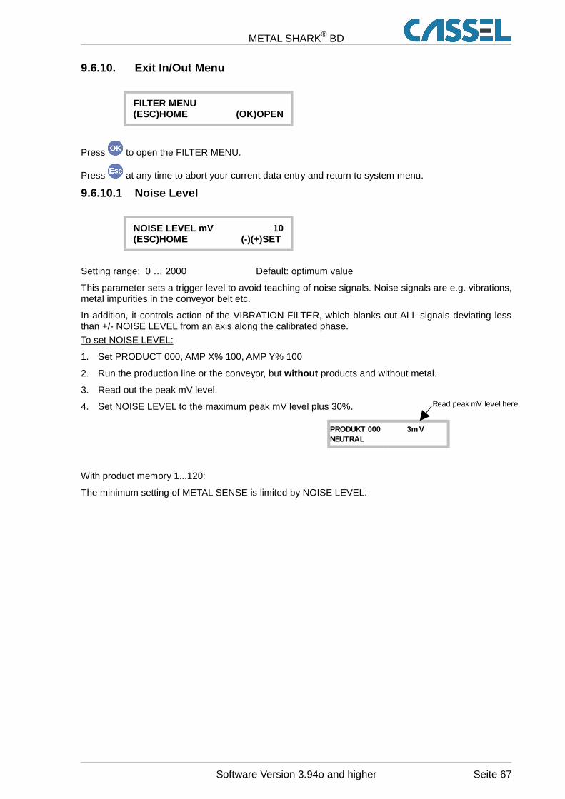
METAL SHARK® BD
9.6.10. Exit In/Out Menu
FILTER MENU(ESC)HOME (OK)OPEN
Press to open the FILTER MENU.
Press at any time to abort your current data entry and return to system menu.
9.6.10.1 Noise Level
NOISE LEVEL mV 10(ESC)HOME (-)(+)SET
Setting range: 0 … 2000 Default: optimum value
This parameter sets a trigger level to avoid teaching of noise signals. Noise signals are e.g. vibrations,metal impurities in the conveyor belt etc.
In addition, it controls action of the VIBRATION FILTER, which blanks out ALL signals deviating lessthan +/- NOISE LEVEL from an axis along the calibrated phase.
To set NOISE LEVEL:
1. Set PRODUCT 000, AMP X% 100, AMP Y% 100
2. Run the production line or the conveyor, but without products and without metal.
3. Read out the peak mV level.
4. Set NOISE LEVEL to the maximum peak mV level plus 30%.
With product memory 1...120:
The minimum setting of METAL SENSE is limited by NOISE LEVEL.
Software Version 3.94o and higher Seite 67
PRODUKT 000 3m VNEUTRAL
Read peak mV level here.
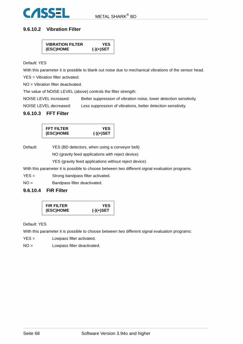
METAL SHARK® BD
9.6.10.2 Vibration Filter
VIBRATION FILTER YES(ESC)HOME (-)(+)SET
Default: YES
With this parameter it is possible to blank out noise due to mechanical vibrations of the sensor head.
YES = Vibration filter activated.
NO = Vibration filter deactivated.
The value of NOISE LEVEL (above) controls the filter strength:
NOISE LEVEL increased: Better suppression of vibration noise, lower detection sensitivity.
NOISE LEVEL decreased: Less suppression of vibrations, better detection sensitivity.
9.6.10.3 FFT Filter
FFT FILTER YES(ESC)HOME (-)(+)SET
Default: YES (BD detectors, when using a conveyor belt)
NO (gravity feed applications with reject device)
YES (gravity feed applications without reject device)
With this parameter it is possible to choose between two different signal evaluation programs.
YES = Strong bandpass filter activated.
NO = Bandpass filter deactivated.
9.6.10.4 FIR Filter
FIR FILTER YES(ESC)HOME (-)(+)SET
Default: YES
With this parameter it is possible to choose between two different signal evaluation programs:
YES = Lowpass filter activated.
NO = Lowpass filter deactivated.
Seite 68 Software Version 3.94o and higher
METAL SHARK® BD
9.6.10.5 GF Mode
GF MODE YES(ESC)HOME (-)(+)SET
Default: NO (BD type, conveyor applications with defined belt speed)
YES (BD type, applications with non-defined speed, e.g. chutes, rollers) YES (all gravity feed applications)
With this parameter it is possible to choose between two different signal evaluation programs:
YES = FFT bandpass filter is set to a wide characteristic.
NO = FFT bandpass filter is set to a very narrow characteristic.
9.6.10.6 Exit Filter Menu
EXIT MENU(ESC)HOME (OK)EXIT
Press to exit the FILTER submenu and return to system menu.
9.6.11. Sensor Menu
Sensor calibration is done by CASSEL to adapt the control unit to the specific sensor settings. Thismenu is only to be opened by the user when CASSEL tells him to check the settings.
VERY IMPORTANT: Never change any value in the facto ry set-up without clear advicefrom Cassel! This would lead to malfunction or dama ge the electronic board.
SENSOR CALIBRATION(ESC)HOME (OK)OPEN
Push to open the submenu SENSOR CALIBRATION.
9.6.11.1 Sensor Field
SENSOR FIELD mm 300(+)(-)SET (ESC)HOME
Setting range: 10 … 999 Default value: refer to LIST OF PARAMETER SET-UP. Do not change default value.
This parameter calibrates the control unit to the dimensions of the sensor. The value is specified byCASSEL. The original value is written on the inside of the control box lid.
Software Version 3.94o and higher Seite 69

METAL SHARK® BD
9.6.11.2 Frequency
FREQUENCY HZ 299600(+)(-)SET (ESC)HOME
Setting range: 290000 … 310000 Default value: refer to LIST OF PARAMETER SET-UP. Do not change default value.
This parameter calibrates the control unit to the sensor resonance frequency. The value is specified byCASSEL. The original value is written on the inside of the control box lid.
9.6.11.3 Balance Factor
BALANCE FACTOR 3(ESC)HOME (-)(+)SET
Setting range: 0 … 110 Default: 6 (BD type, conveyor applications)20 (Gravity feed applications, MESEP SE)
This parameter sets up the regulation speed for the automatic temperature drift compensation circuitof the sensor. Do not change this value.
When BALANCE FACTOR high :
• High changes of temperature and similar noises are compensated.
• The signal of slow moving products and metal parts is also compensated.
9.6.11.4 Phase Calib.
PHASE CALIB. -79.50°(ESC)HOME (-)(+)SET
Default value: refer to LIST OF PARAMETER SET-UP. Do not change this value.
This parameter calibrates the measured product effect phases. The value is specified by CASSEL.The original value is written on the inside of the control box lid.
9.6.11.5 Analog PH
ANALOG PH -12,09°(ESC)HOME (-)(+)SET
Default value: None / Auto Calibrated
This parameter calibrates the measured product effect phases of the main board (pcb). The value isautomatically measured and set when pushing PLUS and MINUS keys simultaneously. During autocalibration process make sure that no metal is inside the sensor head.
9.6.11.6 Exit System Menu
EXIT MENU(ESC)HOME (OK)EXIT
Press to exit the SYSTEM MENU.
Seite 70 Software Version 3.94o and higher
METAL SHARK® BD
9.7. Exit Menu
EXIT MENU(ESC)HOME (OK)EXIT
Press to exit the MENU and return to the main screen.
Software Version 3.94o and higher Seite 71

METAL SHARK® BD
10. Electrical Connections
Only qualified electricians are allowed to perform work inside of electrical cabinets.
10.1. Terminals of Power Supply Board
The connectors are on the left side of the power supply in the main controller box.
GROUND +24V DC relais K2 and K1 Fuse 85-265V AC 45-440Hz
26-28 29-31 32-34 35-37 SI T 1A L1 N PE PE
Terminal # Function Description
26, 27, 28 Ground Ground potential for internal power supply
29, 30, 31 + 24 V DC OUT
Internal Power supply source (max. 100mA)
Relais K232, 33, 34
Error alarmOUT Closed line, potential free, switching capacity 230V AC at 2 A
Relais K135, 36, 37
Metal alarmOUT Closed line, potential free, switching capacity 230V AC at 2 A
L1, N, PE AC Power supplyIN
Mains power supply85 – 265 V AC / 45 – 440 Hz / 100 Watt
10.2. Relais K1, K2 - Function
Relais # Terminal # Power supplyOFF
Error or adjustmode
Operational okmode
Metal alarm
K2
Error
32
33
34
K1
Metal
35
36
37
Seite 72 Software Version 3.94o and higher
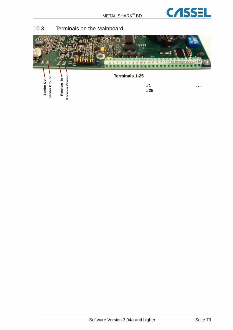
METAL SHARK® BD
10.3. Terminals on the Mainboard
Terminals 1-25
#1 . . .#25
Software Version 3.94o and higher Seite 73
Sen
der
Out
Sen
der
Gro
und
Rec
eive
r In
Rec
eive
r G
roun
d
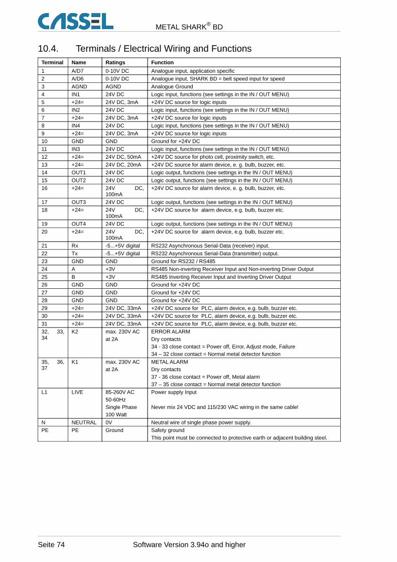
METAL SHARK® BD
10.4. Terminals / Electrical Wiring and FunctionsTerminal Name Ratings Function
1 A/D7 0-10V DC Analogue input, application specific
2 A/D6 0-10V DC Analogue input, SHARK BD = belt speed input for speed
3 AGND AGND Analogue Ground
4 IN1 24V DC Logic input, functions (see settings in the IN / OUT MENU)
5 +24= 24V DC, 3mA +24V DC source for logic inputs
6 IN2 24V DC Logic input, functions (see settings in the IN / OUT MENU)
7 +24= 24V DC, 3mA +24V DC source for logic inputs
8 IN4 24V DC Logic input, functions (see settings in the IN / OUT MENU)
9 +24= 24V DC, 3mA +24V DC source for logic inputs
10 GND GND Ground for +24V DC
11 IN3 24V DC Logic input, functions (see settings in the IN / OUT MENU)
12 +24= 24V DC, 50mA +24V DC source for photo cell, proximity switch, etc.
13 +24= 24V DC, 20mA +24V DC source for alarm device, e. g. bulb, buzzer, etc.
14 OUT1 24V DC Logic output, functions (see settings in the IN / OUT MENU)
15 OUT2 24V DC Logic output, functions (see settings in the IN / OUT MENU)
16 +24= 24V DC,100mA
+24V DC source for alarm device, e. g. bulb, buzzer, etc.
17 OUT3 24V DC Logic output, functions (see settings in the IN / OUT MENU)
18 +24= 24V DC,100mA
+24V DC source for alarm device, e.g. bulb, buzzer etc.
19 OUT4 24V DC Logic output, functions (see settings in the IN / OUT MENU)
20 +24= 24V DC,100mA
+24V DC source for alarm device, e.g. bulb, buzzer etc.
21 Rx -5...+5V digital RS232 Asynchronous Serial-Data (receiver) input.
22 Tx -5...+5V digital RS232 Asynchronous Serial-Data (transmitter) output.
23 GND GND Ground for RS232 / RS485
24 A +3V RS485 Non-inverting Receiver Input and Non-inverting Driver Output
25 B +3V RS485 Inverting Receiver Input and Inverting Driver Output
26 GND GND Ground for +24V DC
27 GND GND Ground for +24V DC
28 GND GND Ground for +24V DC
29 +24= 24V DC, 33mA +24V DC source for PLC, alarm device, e.g. bulb, buzzer etc.
30 +24= 24V DC, 33mA +24V DC source for PLC, alarm device, e.g. bulb, buzzer etc.
31 +24= 24V DC, 33mA +24V DC source for PLC, alarm device, e.g. bulb, buzzer etc.
32, 33,34
K2 max. 230V AC at 2A
ERROR ALARMDry contacts34 - 33 close contact = Power off, Error, Adjust mode, Failure34 – 32 close contact = Normal metal detector function
35, 36,37
K1 max. 230V AC at 2A
METAL ALARMDry contacts37 - 36 close contact = Power off, Metal alarm37 – 35 close contact = Normal metal detector function
L1 LIVE 85-260V AC50-60HzSingle Phase100 Watt
Power supply Input
Never mix 24 VDC and 115/230 VAC wiring in the same cable!
N NEUTRAL 0V Neutral wire of single phase power supply.
PE PE Ground Safety groundThis point must be connected to protective earth or adjacent building steel.
Seite 74 Software Version 3.94o and higher
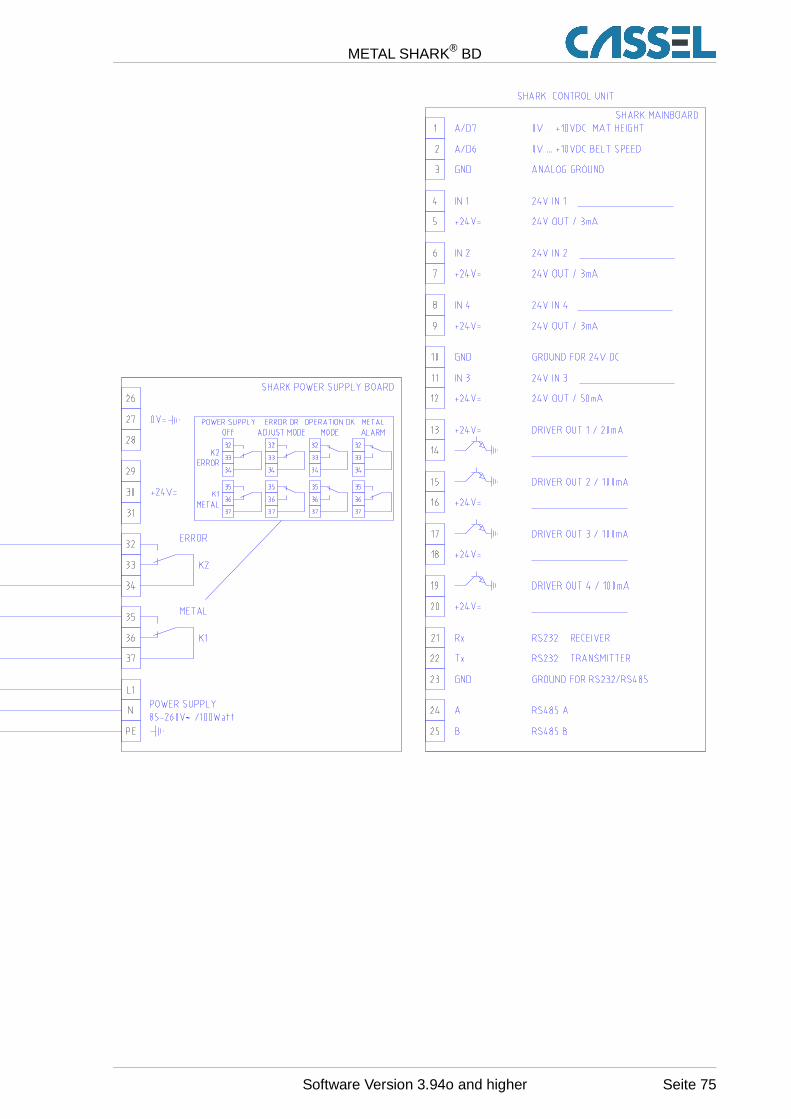
METAL SHARK® BD
~
Software Version 3.94o and higher Seite 75
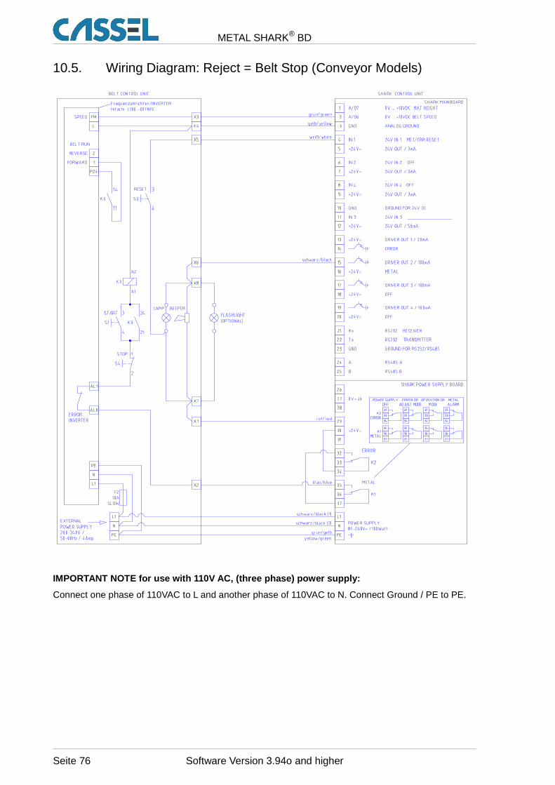
METAL SHARK® BD
10.5. Wiring Diagram: Reject = Belt Stop (Conveyor Models)
~
IMPORTANT NOTE for use with 110V AC, (three phase) power supply:
Connect one phase of 110VAC to L and another phase of 110VAC to N. Connect Ground / PE to PE.
Seite 76 Software Version 3.94o and higher
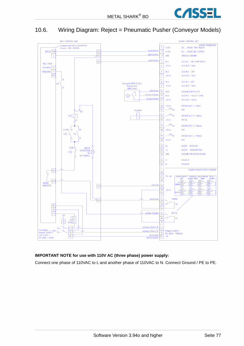
METAL SHARK® BD
10.6. Wiring Diagram: Reject = Pneumatic Pusher (Conveyor Models)
~
IMPORTANT NOTE for use with 110V AC (three phase) p ower supply:
Connect one phase of 110VAC to L and another phase of 110VAC to N. Connect Ground / PE to PE.
Software Version 3.94o and higher Seite 77
METAL SHARK® BD
11. Maintenance and Regular Inspections
11.1. Maintenance
The metal detector is a sensitive measuring device which serves to protect other machinery fromdamage, thus preventing expensive, unscheduled interruptions of production. This manual describeshow to install, operate and adjust the sensitivity. The conveyor belt upon which the metal detector ismounted is designed to ensure that the detector works accurately. The metal detector will generallywork safely and reliably without having to make additional adjustments after the initial commissioning.
11.2. Regular Inspections
Regular tests of the metal detector's functions are very important to ensure safe operations. Thedetector must be tested at least on a weekly basis. Additionally, it has to be tested after eachmaintenance stop or after works have been performed near the detector. If the detector does notfunction appropriately eliminate the malfunctions immediately; if not, machines protected by thedetector must be stopped.
It is recommended to regularly test the metal detector with standardised test objects and to keeprecords of these tests in a log book. Metal testing spheres are generally supplied with the detector.
A suitable metal testing object and a testing schedule should be established for the examination:
• The testing object should be a sphere of the smallest diameter which detection is required. Thesphere can be glued to a piece of plastic or may be cast in. The sphere is passed through thedetector together with the product in order to observe whether a metal detection signal is issued.
• The testing schedule should state when the detector is to be tested and by whom. Example: Theelectrician on duty on a given shift has to test the detector using the testing object one hour afterthe start of each shift. The test results are recorded in the log book with the date, time andsignature. Example: Test object recognised, 24 August 2007, 08.30, signed, Smith.
11.3. Notes
Normally, Cassel adjusts the metal detector to find the smallest metal pieces possible. Thereforeplease consider the following notes:
Keep the conveyor belt clean: Fingermarks and shoe prints, visible or not, may contain metalparticles.
Do not melt or grind near the detector or the conve yor without having covered the conveyor beltwith e.g. Cartboard. Sparks may burn the surface of the conveyor.
Do not change the conveyor belt construction without having asked the manufacturer of detectorand belt.
Seite 78 Software Version 3.94o and higher
METAL SHARK® BD
12. Conveyor Belt System
This chapter is only valid if the metal detector METAL SHARK® was supplied with a conveyor belt as acomplete system.
12.1. Conveyor Belt Maintenance
Please maintain the conveyor belt frequently to to achieve a long service life. We therefore suggestyou to perform inspections on a monthly (1 shift operation) or weekly (2/3 shift operation) basisdepending on operating conditions. During the running-in period the conveyor belt may have to bereadjusted.
1. Check belt tension: The conveyor belt must only be tensioned so that it is just moved by thedriving drum. IMPORTANT: If belt tension is too strong, the roller bearing may be damaged orsubjected to premature wear.
2. Check belt run: If the conveyor belt is to run at the side, the drums will have to be readjusted.The belt always runs to the side which is tensioned less.
3. Clean belt: Never use aggressive detergents.
4. Check belt for damage: Replace the belt if it is considerably damaged.
5. Check bearing of the drive and deflection drum: The bearings are equipped withmaintenance-free tension bearings. The filling of grease is generally adequate for the servicelife of the bearing.
6. Check deflection rollers: The deflection rollers are equipped with maintenance-free bearingsand require no lubrication whatsoever. If you discover any wear, the rollers must be replaced.
7. Check electrical connections and cable entries fo r damage: If you discover damage,repairs must be carried out immediately by expert personnel.
Software Version 3.94o and higher Seite 79
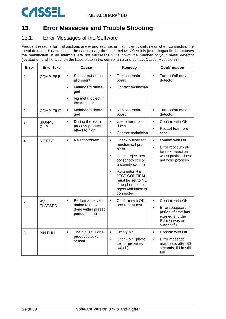
METAL SHARK® BD
13. Error Messages and Trouble Shooting
13.1. Error Messages of the Software
Frequent reasons for malfunctions are wrong settings or insufficient carefulness when connecting themetal detector. Please isolate the cause using the index below. Often it is just a bagatelle that causesthe malfunction. If all attempts are not successful write down the number of your metal detector(located on a white label on the base plate in the control unit) and contact Cassel Messtechnik.
Error Error text Cause Remedy Confirmation
1 COMP. PRE • Sensor out of thealignment
• Mainboard dama-ged
• big metal object inthe detector
• Replace main-board
• Contact technician
• Turn on/off metaldetector
2 COMP. FINE • Mainboard dama-ged
• Replace main-board
• Turn on/off metaldetector
3 SIGNALCLIP
• During the learnprocess producteffect to high
• Use other pro-ducts
• Contact technician
• Confirm with OK
• Restart learn pro-cess
4 REJECT • Reject problem • Check pusher formechanical pro-blem
• Check reject sen-sor (photo cell orproximity switch)
• Parameter RE-JECT CONFIRMmust be set to NO,if no photo cell forreject validation isconnected.
• confirm with OK
• Error reoccurs af-ter next rejectionwhen pusher doesnot work properly
5 PVELAPSED
• Performance vali-dation test notdone within presetperiod of time
• Confirm with OKand repeat test
• Confirm with OK
• Error reappears, ifperiod of time hasexpired and thePV test was un-successful
6 BIN FULL • The bin is full or aproduct blockssensor
• Empty bin
• Check bin (photocell or proximityswitch)
• Confirm with OK
• Error messagereappears after 30seconds, if bin stillfull
Seite 80 Software Version 3.94o and higher
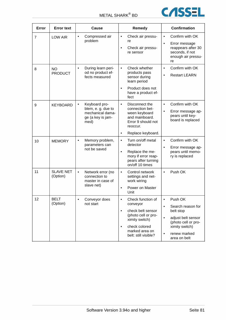
METAL SHARK® BD
Error Error text Cause Remedy Confirmation
7 LOW AIR • Compressed airproblem
• Check air pressu-re
• Check air pressu-re sensor
• Confirm with OK
• Error messagereappears after 30seconds, if notenough air pressu-re
8 NOPRODUCT
• During learn peri-od no product ef-fects measured
• Check whetherproducts passsensor duringlearn period
• Product does nothave a product ef-fect
• Confirm with OK
• Restart LEARN
9 KEYBOARD • Keyboard pro-blem, e. g. due tomechanical dama-ge (a key is jam-med)
• Disconnect theconnection bet-ween keyboardand mainboard.Error 9 should notreoccur.
• Replace keyboard.
• Confirm with OK
• Error message ap-pears until key-board is replaced
10 MEMORY • Memory problem,parameters cannot be saved
• Turn on/off metaldetector
• Replace the me-mory if error reap-pears after turningon/off 10 times
• Confirm with OK
• Error message ap-pears until memo-ry is replaced
11 SLAVE NET(Option)
• Network error (noconnection tomaster in case ofslave net)
• Control networksettings and net-work wiring
• Power on MasterUnit
• Push OK
12 BELT(Option)
• Conveyor doesnot start
• Check function ofconveyor
• check belt sensor(photo cell or pro-ximity switch)
• check coloredmarked area onbelt: still visible?
• Push OK
• Search reason forbelt stop
• adjust belt sensor(photo cell or pro-ximity switch)
• renew markedarea on belt
Software Version 3.94o and higher Seite 81

METAL SHARK® BD
14. Instruction Sheet
14.1. General Function
Target group for this manual: quality checking personnel, HACCP-agent
Start of work:
• Turn on the metal detector and wait about 1 min (alignment time) until the message PRODUCT xxappears on the display and the green LED goes on.
• Retrieve the product relevant product number .
Metal detection:
• Pass numerous metal free samples through the metal detector.
• No metal alarm is to occur.
• Pass a sample with a metal sphere through the metal detector.
• A metal alarm is to occur!
The test intervals must be specified in a way that when an irregularity occurs all products can bechecked again that have run through the metal detector since the last test. Furthermore a test shouldbe made every time a new shift begins and a new product is running through the metal detector.
Production:
You must secure that the metal detector is checking all products systematically and steadily.
Metalliferous product:
You must secure that all metalliferous products are not accidentally reused or delivered to a customer.These products are to be removed from the production and labelled clearly , e. g. with a red label“Locked/metal”.
Seite 82 Software Version 3.94o and higher
METAL SHARK® BD
14.2. General Metal Detector Manual
Target group for this manual: HACCP-agent, ISO9000-manual
ISO 9000:
The metal detector is installed to protect our customers from metallic impurity in their products.
HACCP:
The metal detector is a crucial “physical” control point against the danger of a metal impurity. It ispossible that when you do not have this control a health risk occurs.
Method of operation:
The metal detector establishes an electro magnetic field in the search coil. This field changes when ametal passes through. Then a metal alarm is set off.
A metal detector reacts on magnetism and electric conductivity.
Operating instructions:
• In order to minimize interferences do not install any mobile metal parts near the search coil.
• The search coil must be free from vibrations. Do not put any objects on the search coil.
• The settings in the specific operating instructions of our products must be made.
• Always take metal alarms seriously. You have to look for the source of the metal impurity.
• Most food is conductive. Therefore the metal detector has to learn the product effect and blank itout.
Additional hints:
Withdraw the regular metal detector check from the specific operating instructions.
Inform the HACCP-agent about irregularities and error messages.
Software Version 3.94o and higher Seite 83
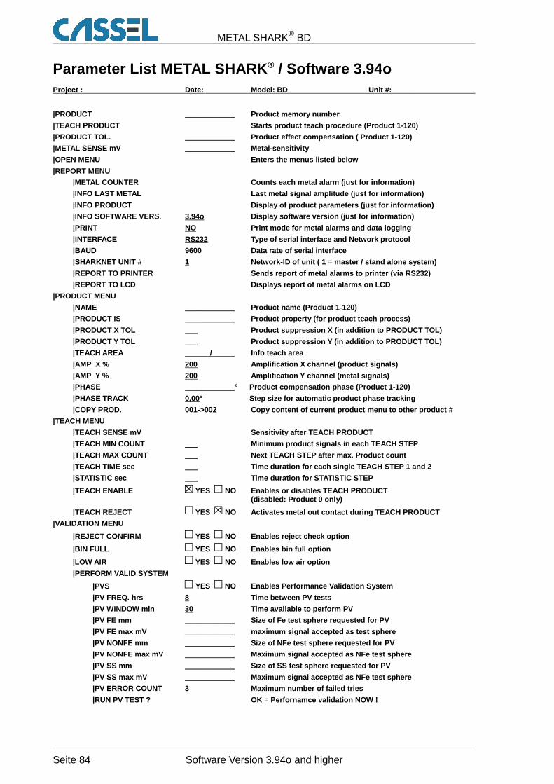
METAL SHARK® BD
Parameter List METAL SHARK ® / Software 3.94oProject : Date: Model: BD Unit #:
|PRODUCT ____________ Product memory number
|TEACH PRODUCT Starts product teach procedure (Product 1-120)
|PRODUCT TOL. ____________ Product effect compensation ( Product 1-120)
|METAL SENSE mV ____________ Metal-sensitivity
|OPEN MENU Enters the menus listed below
|REPORT MENU
|METAL COUNTER Counts each metal alarm (just for inf ormation)
|INFO LAST METAL Last metal signal amplitude (just f or information)
|INFO PRODUCT Display of product parameters (just for information)
|INFO SOFTWARE VERS. 3.94o Display software version (just for information)
|PRINT NO Print mode for metal alarms and data logging
|INTERFACE RS232 Type of serial interface and Network protocol
|BAUD 9600 Data rate of serial interface
|SHARKNET UNIT # 1 Network-ID of unit ( 1 = master / stand alone syste m)
|REPORT TO PRINTER Sends report of metal alarms to p rinter (via RS232)
|REPORT TO LCD Displays report of metal alarms on LC D
|PRODUCT MENU
|NAME ____________ Product name (Product 1-120)
|PRODUCT IS ____________ Product property (for product teach process)
|PRODUCT X TOL ___ Product suppression X (in addition to PRODUCT TOL)
|PRODUCT Y TOL ___ Product suppression Y (in addition to PRODUCT TOL)
|TEACH AREA / Info teach area
|AMP X % 200 Amplification X channel (product signals)
|AMP Y % 200 Amplification Y channel (metal signals)
|PHASE ____________° Product compensation phase (Product 1-120)
|PHASE TRACK 0,00 ° Step size for automatic product phase tracking
|COPY PROD. 001->002 Copy content of current product menu to other product #
|TEACH MENU
|TEACH SENSE mV Sensitivity after TEACH PRODUCT
|TEACH MIN COUNT ___ Minimum product signals in each TEACH STEP
|TEACH MAX COUNT ___ Next TEACH STEP after max. Product count
|TEACH TIME sec ___ Time duration for each single TEACH STEP 1 and 2
|STATISTIC sec ___ Time duration for STATISTIC STEP
|TEACH ENABLE YES NO Enables or disables TEACH PRO DUCT(disabled: Product 0 only)
|TEACH REJECT YES NO Activates metal out contact d uring TEACH PRODUCT
|VALIDATION MENU
|REJECT CONFIRM YES NO Enables reject check option
|BIN FULL YES NO Enables bin full option
|LOW AIR YES NO Enables low air option
|PERFORM VALID SYSTEM
|PVS YES NO Enables Performance Validation System
|PV FREQ. hrs 8 Time between PV tests
|PV WINDOW min 30 Time available to perform PV
|PV FE mm ____________ Size of Fe test sphere requested for PV
|PV FE max mV ____________ maximum signal accepted as test sphere
|PV NONFE mm ____________ Size of NFe test sphere requested for PV
|PV NONFE max mV ____________ Maximum signal accepted as NFe test sphere
|PV SS mm ____________ Size of SS test sphere requested for PV
|PV SS max mV ____________ Maximum signal accepted as NFe test sphere
|PV ERROR COUNT 3 Maximum number of failed tries
|RUN PV TEST ? OK = Perfornamce validation NOW !
Seite 84 Software Version 3.94o and higher
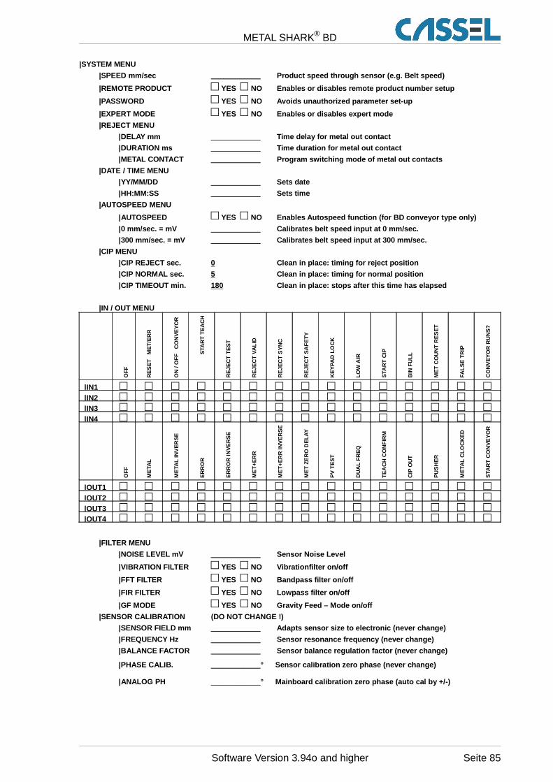
METAL SHARK® BD
|SYSTEM MENU
|SPEED mm/sec ____________ Product speed through sensor (e.g. Belt speed)
|REMOTE PRODUCT YES NO Enables or disables remote product number setup
|PASSWORD YES NO Avoids unauthorized parameter set -up
|EXPERT MODE YES NO Enables or disables expert mod e
|REJECT MENU
|DELAY mm ____________ Time delay for metal out contact
|DURATION ms ____________ Time duration for metal out contact
|METAL CONTACT ____________ Program switching mode of metal out contacts
|DATE / TIME MENU
|YY/MM/DD ____________ Sets date
|HH:MM:SS ____________ Sets time
|AUTOSPEED MENU
|AUTOSPEED YES NO Enables Autospeed function (for BD conveyor type only)
|0 mm/sec. = mV ____________ Calibrates belt speed input at 0 mm/sec.
|300 mm/sec. = mV ____________ Calibrates belt speed input at 300 mm/sec.
|CIP MENU
|CIP REJECT sec. 0 Clean in place: timing for reject position
|CIP NORMAL sec. 5 Clean in place: timing for normal position
|CIP TIMEOUT min. 180 Clean in place: stops after this time has elapsed
|IN / OUT MENU
OF
F
ME
T/E
RR
RE
SE
T
CO
NV
EY
OR
O
N /
OF
F STA
RT
TE
AC
H
RE
JEC
T T
ES
T
RE
JEC
T V
ALI
D
RE
JEC
T S
YN
C
RE
JEC
T S
AF
ET
Y
KE
YPA
D L
OC
K
LOW
AIR
STA
RT
CIP
BIN
FU
LL
ME
T C
OU
NT
RE
SE
T
FALS
E T
RIP
CO
NV
EY
OR
RU
NS
?
|IN1|IN2|IN3|IN4
OF
F
ME
TAL
ME
TAL
INV
ER
SE
ER
RO
R
ER
RO
R IN
VE
RS
E
ME
T+E
RR
ME
T+
ER
R IN
VE
RS
E
ME
T Z
ER
O D
ELA
Y
PV
TE
ST
DU
AL
FR
EQ
TE
AC
H C
ON
FIR
M
CIP
OU
T
PU
SH
ER
ME
TAL
CLO
CK
ED
STA
RT
CO
NV
EY
OR
|OUT1|OUT2|OUT3|OUT4
|FILTER MENU
|NOISE LEVEL mV ____________ Sensor Noise Level
|VIBRATION FILTER YES NO Vibrationfilter on/off
|FFT FILTER YES NO Bandpass filter on/off
|FIR FILTER YES NO Lowpass filter on/off
|GF MODE YES NO Gravity Feed – Mode on/off
|SENSOR CALIBRATION (DO NOT CHANGE !)
|SENSOR FIELD mm ____________ Adapts sensor size to electronic (never change)
|FREQUENCY Hz ____________ Sensor resonance frequency (never change)
|BALANCE FACTOR ____________ Sensor balance regulation factor (never change)
|PHASE CALIB. ____________ ° Sensor calibration zero phase (never change)
|ANALOG PH ____________ ° Mainboard calibration zero phase (auto cal by +/-)
Software Version 3.94o and higher Seite 85
METAL SHARK® BD
Cassel Messtechnik GmbH
In der Dehne 10
37127 Dransfeld - Germany
Tel.: +49-5502-91150
Fax.: +49-5502-911532
Internet: www.cassel.de
Email: [email protected]
Original Manual / Documentation for Metal Detector METAL SHARK® BD
Updated: 8 December 2008
Seite 86 Software Version 3.94o and higher


![l>lf·· E ·B; -I,:,C-·-1·1V · cat. no.i bd lj.657 bd lj.6]5 bd 4630 bd 4·627 bd 4628 bd 4886 bd 4546 bd 4·545 bd 4544 bd 4542 bd lj,588 bd lj.593 bd 0102 bd 4636 bd 4632 bd](https://static.fdocuments.net/doc/165x107/5f7c69bb7d840d18665ab1e6/llf-e-b-ic-11v-cat-noi-bd-lj657-bd-lj65-bd-4630-bd-4627-bd-4628-bd.jpg)