Met Strut 2009
88
Metstrut cable management www.metsec.com CI/SfB April 2009 (6-) Hh2
description
tray
Transcript of Met Strut 2009

Metsec plcBroadwell Road, Oldbury, West Midlands, B69 4HFTel: 44+ (0) 121 601 6085Fax: 44+ (0) 121 601 6177email: [email protected]
Metstrut DivisionCable Management and Channel Systems for M&E SupportTel: +44(0) 121 601 6085Fax: +44(0) 121 601 [email protected]
Purlin DivisionZ and C-Sections for Building Shell ApplicationsC-Sections for Mezzanine FloorsTel: +44(0) 121 601 6000Fax: +44(0) 121 601 [email protected]
Lattice Joist DivisionLightweight Lattice Joists and TrussesTel: +44(0) 121 601 6000Fax: +44(0) 121 601 [email protected]
Framing DivisionFast-Track Steel Building SystemsTel: +44(0) 121 601 6000Fax: +44(0) 121 601 [email protected]
Hepsec DivisionDry Linings, Partitioning and Ceiling SupportSystemsTel: +44(0) 2476 585600Fax: +44(0) 2476 [email protected]
Metsec plc is a member of the Profilform Divisionof the voestalpine group with companies inAustria, Belgium, Brazil, Czech Republic, France,Germany, Russia and the U.S.A.
© Copyright METSEC plc 2008
In the interests of a policy of continuous research and development,
Metsec Building Products Ltd reserve the right to change the
specifications in this publication without prior notice.
Metstrut cablemanagement
www.metsec.com
CI/SfBApril 2009
(6-) Hh2
Mets
trut c
ab
le m
anag
em
ent
CI/S
fB(6-)
Hh2
486.5 Metstrut Cover:Layout 1 17/4/09 10:38 Page 1

486.5 Metstrut final-04:Layout 1 17/4/09 10:35 Page 2

3
Product range summary 6-7
Cable ladder systems 8-31
Cable tray systems 32-49
Cable trunking systems 50-63
Metal framing system 64-77
Metsec: investing in quality and service 4-5
Product description 8-11Technical and standards 12-13Product footprints 14Products and accessories 15-31
Product description 32-35Technical and Standards 36-37Product footprints 38Products and accessories 39-49
Product description 50-53Technical and standards 54-55Standard distribution trunking and accessories 56-61Lighting trunking and accessories 62-63
Product description 64-65Technical and Standards 66-67Channel profiles and load tables 68-73Cantilever arms and load tables 74Channels 75Channel nuts 75Brackets 76-77
Rapid installation system 78-84
Product description 78-79Technical and standards 80Channel profiles and load tables 81Cantilever arms and load tables 82Channels 83Accessories 83Brackets 84
Pre fabrication service 86-87
Cut to length serviceTwo dimensional framesThree dimensional framesPre installed cable management
Contents
Fasteners 85
486.5 Metstrut final-04:Layout 1 17/4/09 10:35 Page 3

Investing in quality and serviceThe CompanyMetsec plc is the UK’s largest specialist cold roll-forming company, providing structural steelcomponents for the UK construction andmanufacturing industries. We have beenestablished for over 75 years and are based inOldbury in the West Midlands.
Today, Metsec are part of the Profilform Divisionof voestalpine - the world’s largest manufacturerof cold roll-formed sections, with a globalnetwork producing over 800,000 tonnes of coldrolled steel per annum.
We focus on adding value through expert design,precision manufacturing and on-time, in-fullproduct delivery. Our aim is to provide excellentservice and quality products that offer ourcustomers cost effective solutions.
Metstrut systemsMetstrut enjoys the technical expertise of over60 years of cold roll forming and structural designassociated with the market leader status of theMetsec Building Products Division. This has ledto the development of fully integrated productsand systems for use within the constructionindustry that provide innovative and costeffective solutions for the support of mechanicaland electrical services within an increasinglydemanding market.
Metstrut cable management systems includecable ladder, cable tray, cable trunking fordistribution and lighting, as well as acomprehensive metal framing system thatincludes rapid installation components that cansave some 50% of installation time on site.
Metstrut also offers a prefabrication service foroff site modules, both bolted and weldedconstruction including pre-installed Metstrutcable management components if required.
QualityMetsec operates strict design and qualityprocedures through a Quality ManagementSystem accredited to BS EN ISO 9001:2008 which covers both our design and manufacturingoperations.
This commitment to quality ensures that weprovide the highest levels of performancethroughout our operations, ensuring the highestlevel of customer satisfaction.
4
Introduction
486.5 Metstrut final-04:Layout 1 17/4/09 10:35 Page 4

5
Introduction and components
SustainabilityCertification
Metsec and voestalpine both regard the issue ofsustainability as a core social, as well ascorporate, responsibility.
This has been recognised by the award of BS EN ISO 14001:2004 for our EnvironmentalManagement System.
Metsec were the first cold roll-forming companyto be awarded the prestigious gold standardunder the Steel Construction SustainabilityCharter.
Additionally, Metsec recognise thatenvironmental responsibility is both a local aswell as a global issue. We were therefore pleasedto be awarded the Sandwell Borough PlatinumEnvironmental Charter Award following an auditof our Environmental management proceduresand award of BS EN ISO 14001:2004.
Design
Our market-leading Metstrut DesignSPEC designsoftware provides cost effective solutions tomaximise the design efficiency of installations.Comprehensive technical support is provided byour design office.
The latest version of Metstrut DesignSPEC offersthe unique advantage of being able to substitutelighter gauge profiles to value engineer thedesign of support systems into cost effectivesolutions.
For full details on our technical support service orto obtain a free copy of Metstrut DesignSPECplease contact us on 0121 601 6085.
5
“The baseline SPeAR® diagram shows a well balanced performance in terms of sustainability, and that Metsec is already meeting legislation or best practice in the large majority of areas. In some cases Metsec is starting to move beyond best practice.”
Re-use and recycling
Steel is one of the World’s most recycledmaterials. According to the British ConstructionalSteelwork Association (BCSA), recovery rates forsteel components from building demolition sitesare 84% for recycling and 10% for re-use*. This gives a total potential recovery and re-use factor of steel from buildings of anincredible 94%.
* BCSA publication no. 35/03
SPeAR®
Independently, as well as with voestalpine,Metsec will continue to pursue sustainability as akey business objective. The cornerstone of this isthe very thorough and detailed societal, economicand environmental sustainability review of ouroperations carried out in the SPeAR® (SustainableProject Appraisal Routine) Report from Arup.This report gives us both an assessment of ourcurrent environmental position as well asidentifying key areas for improvement in thefuture.
To quote from the report:
486.5 Metstrut final-04:Layout 1 17/4/09 10:35 Page 5
6
Product range summary
Introduction
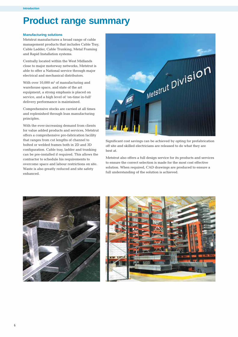
Manufacturing solutionsMetstrut manufactures a broad range of cablemanagement products that includes Cable Tray,Cable Ladder, Cable Trunking, Metal Framingand Rapid Installation systems.
Centrally located within the West Midlandsclose to major motorway networks, Metstrut isable to offer a National service through majorelectrical and mechanical distributors.
With over 10,000 m2 of manufacturing andwarehouse space, and state of the artequipment, a strong emphasis is placed onservice, and a high level of ‘on-time in-full’delivery performance is maintained.
Comprehensive stocks are carried at all timesand replenished through lean manufacturingprinciples.
With the ever-increasing demand from clientsfor value added products and services, Metstrutoffers a comprehensive pre-fabrication facilitythat ranges from cut lengths of channel tobolted or welded frames both in 2D and 3Dconfiguration. Cable tray, ladder and trunkingcan be pre-installed if required. This allows thecontractor to schedule his requirements toovercome space and labour restrictions on site.Waste is also greatly reduced and site safetyenhanced.
Significant cost savings can be achieved by opting for prefabricationoff site and skilled electricians are released to do what they are best at.
Metstrut also offers a full design service for its products and servicesto ensure the correct selection is made for the most cost effectivesolution. When required, CAD drawings are produced to ensure afull understanding of the solution is achieved.
486.5 Metstrut final-04:Layout 1 17/4/09 10:35 Page 6

7
“
Product range summary
Product rangeCable ladder systems
Metstrut cable ladder systems are widelyaccepted due to their strength to weight ratioand simplicity of design. Easily installed andwith a comprehensive range of accessories,Metstrut cable ladder systems can be found inapplications throughout the UK, Ireland andmainland Europe.
Cable tray systems
Metstrut cable tray systems have been designedafter considerable consultation with end usersand installers to arrive at a final design thatsatisfies all of their requirements. Each cabletray range features a unique slotting pattern inthe base and the return flange ranges haveslotted sides. Additionally, each tray range hasthe same footprint to aid setting out when finalloadings are not yet available.
Cable trunking systems
Metstrut cable trunking systems are availableas standard distribution trunking and also aslighting trunking. Manufactured on state ofthe art computer controlled equipment with ahigh level of automation, Metstrut cabletrunking is of economic design to providecompetitive solutions.
Metal framing systems
Metstrut offers the traditional channel system ina variety of profiles and gauges with a largerange of fittings and fasteners. The fully testedsystem can be reliably used for a wideapplication base for the support of mechanicaland electrical services.
A Rapid Installation version is also availablewith a unique channel profile and pre-assembled fittings with integral fixings. By using this product range, installation timesare drastically reduced.
Both systems can be fully integrated for totalflexibility.
486.5 Metstrut final-04:Layout 1 17/4/09 10:35 Page 7

Cable ladder systems
Cable ladder systems
8
These sectors include:* Commercial* Education* Health* Oil and Gas* Petrochemical* Power Generation* Retail* Telecoms* Tunnels
The comprehensive Metstrut cable ladder rangeconsists of four systems commencing with the50mm deep light duty, up to the150mm deepextra heavy duty, all with a wide offering ofaccessories.
Slotted side rails whilst allowing easyconnection to each other also allows site cutladders to be connected generally without theneed to drill. Additionally, Metstrut cableladders have an excellent strength to weightratio providing a versatile approach to thesupport of cables.
For projects requiring long, straight runs ofcable ladder, Metstrut manufactures to order 6mlengths of straight ladder that speeds up theinstallation process and reduces the number ofsplice plates required for an even more costeffective solution. This would be particularlyapplicable to tunnel projects and large powerstations or petrochemical installations.
Metstrut is a leading manufacturer of cableladder for not only the UK market, but alsomanufactures for export. European widths ofcable ladder are available in increments of100mm up to 900mm wide.
Rung configurations are traditionally with openfaces alternately positioned up and down at300mm centres. Cable ladders with rungsfacing all down or all up are also available toorder.
Offering comprehensive design solutions andflexible production through lean manufacturingprinciples, and with a very high on-time and in-full delivery performance, Metstrut has earnedthe reputation for its high level of service.
Development and testingMetstrut cable ladder systems have beendeveloped in house and fully supported byindependent testing in the Department ofMechanical Engineering at the University ofStrathclyde.
Further verification testing has also beencarried out under the requirements ofBS EN 61537:2007 - cable management -cable tray systems and cable ladder systems.These tests include: impact resistance,marking, connection of re-usable components,safe working load tests, electrical continuity,and performance of steel at extremetemperature ranges.
Metstrut cable ladder systems have beendeveloped to provide cost effectivesolutions for the support of cables in awide range of market sectors.
486.5 Metstrut final-04:Layout 1 17/4/09 10:35 Page 8

9
Load tablesSafe load tables areprovided in a uniqueformat for easy comparisonand cost optimisation.Load tables assume aneven distribution of loadacross the width of theladder fixed in a horizontalplane, and that the loadingis similar on at least two ormore continuous spans.For non-uniform loads orspans/loadings outside thescope of the tables, pleasecontact Metstrut for advice.
Cable ladder systems
Example:-Load required = 100kg per linear metreOptions available:-1. 50mm deep ladder will span up to a maximum of 2.396m with a deflection of 10.9mm2. 100mm deep ladder will span up to a maximum of 3.952m with a deflection of 14.8mm3. 125mm deep ladder will span up to a maximum of 5.321m with a deflection of 21.4mm4. 150mm deep ladder will span up to a maximum of 6.000m with a deflection of 21.8mm
Ladder table
LOAD TYPE
w 50mm deep 100mm deep 125mm deep 150mm deep
kg/m s d dp s d dp s d dp s d dp
25 3.931 19.7 19.7 6.000 19.6 30.0 6.000 8.7 30.0 6.000 5.4 30.0
50 3.120 15.6 15.6 5.487 27.4 27.4 6.000 17.3 30.0 6.000 10.9 30.0
75 2.725 13.6 13.6 4.564 19.7 22.8 6.000 26.0 30.0 6.000 16.3 30.0
100 2.396 10.9 12.0 3.952 14.8 19.8 5.321 21.4 26.6 6.000 21.8 30.0
125 2.143 8.7 10.7 3.535 11.8 17.7 4.760 17.1 23.8 5.476 18.9 27.4
150 1.956 7.2 9.8 3.227 9.8 16.1 4.345 14.3 21.7 4.999 15.7 25.0
175 1.811 6.2 9.1 2.988 8.4 14.9 4.023 12.2 20.1 4.628 13.5 23.1
200 1.694 5.4 8.5 2.795 7.4 14.0 3.763 10.7 18.8 4.329 11.8 21.6
225 1.597 4.8 8.0 2.635 6.6 13.2 3.548 9.5 17.7 4.081 10.5 20.4
250 1.515 4.3 7.6 2.500 5.9 12.5 3.366 8.6 16.8 3.872 9.4 19.4
275 1.445 3.9 7.2 2.383 5.4 11.9 3.209 7.8 16.0 3.692 8.6 18.5
300 1.383 3.6 6.9 2.282 4.9 11.4 3.072 7.1 15.4 3.535 7.9 17.7
‘s’– maximum spacing of supports in metres‘d’– maximum deflection in end span in mm‘dp’– allowable deflection (span/200) in mm‘w’– safe working load in kg per linear metre
486.5 Metstrut final-04:Layout 1 17/4/09 10:35 Page 9

10
System configuration and supportMetstrut cable ladders are designedas a complete system with simpleaccessories for ease of installation.Splice plates are supplied completewith M10 cup square bolts, shakeproof washers, and nuts with a hightolerance fit for optimum structuralperformance.
When installing Metstrut cableladders, care should be taken toensure the support is within 600mmof a joint. Accessories (e.g. bends,tees, crossovers etc.) should haveadequate support with additionalsupports for larger components.
Technical construction detailsWhilst rungs are alternatelyreversed as standard, other rungorientations can be produced toorder. Additionally alternativewidths are also available to meetthe requirements of the Europeanmarkets.
28
15
41
21
11.0mm x 38mm long slot holesat 60mm centres in side rails
Rungs alternatelyreversed as standard at300mm max. centres
Cable ladder systems
Rung types
Straight length
Splice plates
Straight length
Crossover
Splice plate
Equal tee
Straight ladder
22mm x 11mm slots at 25mm crs30mm x 11mm slots at 50mm crs
100, 125 & 150mm deep ladder rangesrung type: 41mm x 21mm channel
50mm deep ladder rangerung type: 28mm x 15mm channel
Left hand reducer
Cable ladder systems
486.5 Metstrut final-04:Layout 1 17/4/09 10:35 Page 10

11
50
21
31
50mm deep range(1.5mm thick side rails)
100
21
100mm deep range(1.5mm thick side rails)
70
125
150
21
21
95
150mm deep range(2.0mm thick side rails)
125mm deep range(2.0mm thick side rails)
120
Ladder profiles
Cable ladder systems
Cable ladder systems
Splice plate
Straight reducer
90° Flat bend
External riser
Splice plates
Splice plates
Splice plates
Splice plates
Splice plates
External riser
90° flat bend
Internal riser
Materials and finishesMaterials and finishes available aremild steel hot dip galvanised aftermanufacture as standard and stainlesssteel grade 316 to order.
Mild steel hot dip galvanised:manufactured from steel complyingwith BS EN 10025-2:2004 and hot dipgalvanised after manufacture to BS EN 1461:1999.
Stainless steel: manufactured fromstainless steel grade 316L complyingwith BS EN 10088-2:2005 (picklingand passivating on request).
Light duty
Medium duty
Heavy duty
Extra heavy duty
Splice plates
Splice plates
486.5 Metstrut final-04:Layout 1 17/4/09 10:35 Page 11

Standards
12
Cable ladder systems
Metstrut Cable Ladder Systems generally conform to BS EN 61537:2007 Cable management - cable traysystems and cable ladder systems
Information relating to compliance is detailed/highlightedwithin the following sections of the standard:
6 Classification6.1 According to material6.1.1 Metstrut cable ladder systems are metallic systemcomponents
6.2 According to resistance to flame propagation6.6.2 Metstrut cable ladder systems are non - flamepropagating system components
6.3 According to electrical continuity characteristics6.3.2 Metstrut cable ladder systems have electricalcontinuity characteristics
6.4 According to electrical conductivity6.4.1 Metstrut cable ladder systems are electricallyconductive system components
6.5 According to resistance against corrosion6.5.2 Metstrut cable ladder systems are made of steel withmetallic finishes or stainless steel
(Resistance to corrosion is classified according toTable 1. and follow the relevant specification inTable 8, with compliance according to Table 7.)
Table 1 - classification for resistance against corrosion
Class Reference - material and finish
0 (a) None
1 Electroplated to a minimum thickness of 5 µm
2 Electroplated to a minimum thickness of 12 µm
3 Pre - galvanised to grade 275 to EN 10327 and EN 10326
4 Pre - galvanised to grade 350 to EN 10327 and EN 10326
5 Post - galvanised to a zinc mean coating thickness (minimum) of 45 µm according to ISO 1461 for zinc thickness only
6 Post - galvanised to a zinc mean coating thickness (minimum) of 55 µm according to ISO 1461 for zinc thickness only
7 Post - galvanised to a zinc mean coating thickness (minimum) of 70 µm according to ISO 1461 for zinc thickness only
8 Post - galvanised to a zinc mean coating thickness (minimum) of 85 µm according to ISO 1461 for zinc thickness only
9A Stainless steel manufactured to ASTM: A 240/A 240M - 95a designation S30400 or EN 10088 grade 1 - 4301 without a post treatment (b)
9B Stainless steel manufactured to ASTM: A 240/A 240M - 95a designation S31603 or EN 10088 grade 1 - 4404 without a post treatment (b)
9C Stainless steel manufactured to ASTM: A 240/A 240M - 95a designation S30400 or EN 10088 grade 1 - 4301 with a post treatment (b)
9D Stainless steel manufactured to ASTM: A 240/A 240M - 95a designation S31603 or EN 10088 grade 1 - 4404 with a post treatment (b)
(a) For materials which have no declared corrosion resistance classification
(b) The post - treatment process is used to improve the protection against crevice crack corrosion and the contamination by other steels
Table 7 - System component compliance and classification forresistance against corrosionSystem component Classification Compliance Subclause forMaterial and finishes according to compliance check
Non - metallic 6.5.1 Declaration 14.2.1
Reference - 6.5.2 Table 1 Declaration 14.2.2zinc coating classes 1 to 8 or measurementas in Table 1.
Non - referenced zinc 6.5.2 Table 1 By neutral salt 14.2.3coating classes 1 to 8 spray test NSS
Reference - stainless 6.5.2 Table 1 Declaration 14.2.2steel as in Table 1. Class 9A to 9D
Non-referenced Not classified Declaration Nonestainless steel
Other metallic coatings 6.5.2 Table 1 By neutral salt 14.2.3Column 1 classes spray test NSS1 to 8
Aluminium alloys or other 6.5.3 Under Under 14.2.4metals consideration consideration
Organic coatings 6.5.4 Under Under 14.2.5consideration consideration
Table 8 - Zinc coating thickness of referencematerialsClass Minimum Minimum coating Mean coating
thickness thickness as given in thickness (minimum)EN 10327 or EN 10326 to ISO 1461
µm µm µm0 (a) - - -1 5 - -2 12 - -3 - 15 -4 - 19 -5 - - 456 - - 557 - - 708 - - 85
(a) As declared by the manufacturer or responsible vendor
486.5 Metstrut final-04:Layout 1 17/4/09 10:35 Page 12

13
Cable ladder systems
6.6 According to temperature6.6.1 Minimum temperature for the system components isgiven in Table 2.6.6.2 Maximum temperature for the system components isgiven in Table 3.
6.8 According to the free base area of the cable ladderlength as given in Table 5.
Table 2 - Minimumtemperature classification
Minimum transport, storage
installation and application
temperature °C
+5
- 5
- 15
- 20
- 40
- 50
Table 5 - Free base area classificationClassification Perforation in the free base area
X Up to 80 %Y Over 80 % and up to 90 %Z More than 90 %
Note Classification Z relates to IEC 60364 - 5 - 52Subclause A.52.6.2 third paragraph
Table 3 - Maximumtemperature classification
Maximum transport, storage
installation and application
temperature °C
+40
+60
+90
+105
+120
+150
6.9 According to impact resistance6.9.5 System component offering impact resistance up to50 J (as verified by testing in accordance with 10.9 Test forimpact resistance.)
7 Marking and documentation7.1 Each system component is marked by a label. Labelsused fully comply with the rubbing test. Boxed items arelabelled on the packaging
8 Dimensions
Key cross sectional dimensions for straight cable laddersPart No. External Internal External Internal X-sectional
depth mm depth mm width mm width mm area mm2
(Internal)
LSL050/0150# 50 31.0 192 150 4650LSL050/0300# 50 31.0 342 300 9300LSL050/0450# 50 31.0 492 450 13950
LSL100/0150# 100 70.0 192 150 10500LSL100/0300# 100 70.0 342 300 21000LSL100/0450# 100 70.0 492 450 31500LSL100/0600# 100 70.0 642 600 42000LSL100/0750# 100 70.0 792 750 52500LSL100/0900# 100 70.0 942 900 63000
LSL125/0150# 125 95.0 192 150 14250LSL125/0300# 125 95.0 342 300 28500LSL125/0450# 125 95.0 492 450 42750LSL125/0600# 125 95.0 642 600 57000LSL125/0750# 125 95.0 792 750 71250LSL125/0900# 125 95.0 942 900 85500
LSL150/0150# 150 120.0 192 150 18000LSL150/0300# 150 120.0 342 300 36000LSL150/0450# 150 120.0 492 450 54000LSL150/0600# 150 120.0 642 600 72000LSL150/0750# 150 120.0 792 750 90000LSL150/0900# 150 120.0 942 900 108000
Minimum internal radius of fittingsMinimal internal radius of fittings available for theaccommodation of cables is 300 mm.
9 Construction9.1 Surfaces of system components which are likely tocome into contact with cables during installation areinspected to ensure they shall not cause damage to thecables when installed correctly.
9.2 As with all metallic system components, care should beexercised that handling is in accordance with the relativeCOSHH regulations and gloves should be worn.
9.3 Screwed connections have been designed to withstandthe mechanical stresses occurring during installations andnormal use and will not cause damage to cables whencorrectly inserted. Screwed connections are in general ISOmetric threads fully compliant to tests in accordance with9.3.1 and 9.3.2 of the standard. Metstrut Cable LadderSystems are usually assembled using M10 cup squarebolts and hex nuts with lock washers for couplers etctightened to a torque of 45N/m. Other connections requireM10 hex bolts for clamps etc tightened to a torque of25N/m.
10 Mechanical propertiesCable ladder lengths have been tested generally inaccordance with the standard under 10.2 and 10.3 forverification of the loading graphs. It should be noted thatindependent testing has been carried out to verify thestructural performance of the cable ladders at theminimum and maximum temperature classifications fortest conditions under 10.2.2.
All accessories eg bends, tees etc should be directlysupported by a suitable support device or devices atappropriate positions.
486.5 Metstrut final-04:Layout 1 17/4/09 10:35 Page 13

Accessory footprint
Cable ladder systems
Cable ladder systems
Length = 150mm + radius + width
90 Deg flat bend
Equal tee Unequal tee
90 Deg riser Straight or right/left hand reducer
Crossover
Radius
Radius
Radius
Radius
Radius
Radius
RadiusRadius
Radius
Radius
150Width
Length = 80mm + (Radius-30)
(Radius-30)
(Radius-30)Length = 80+ (Radius-30)
80
80
Length = 300mm + 2 x radius + width
Length = 300mm+ 2 x radius + width
Radius
Radius
Radius
Radius150
150
150
150Width
Length = 300mm + 2 x radius + width
Radius Radius150 150Width
Length = 300mm + 2 x radius + width 2
Radius Radius150 150
500200200
500200200
Width 2
WidthLength = 150mm+ radius + width
Radius
150
Width
Length = 150mm+ radius + width
Radius
150
Width
Length = 150mm+ radius + width 1
Radius
150
Width 1
Width 2
Width 2
Width 1
Width 1
Straight or right/left hand reducer
500200200
500200200
Width 2
Width 2
Width 1
Width 1
14
Cable ladder — accessory foot printstandard radius is 300mm
Footprints are identical for all ranges
486.5 Metstrut final-04:Layout 1 17/4/09 10:35 Page 14

Straight lengths
Cable ladder systems
Unequal tee
Straight or right/left hand reducer
Crossover
Radius
Radius
Radius
RadiusRadius
)
Length = 300mm + 2 x radius + width
Length = 300mm+ 2 x radius + width
Radius
Radius
Radius
Radius150
150
150
150Width
Length = 300mm + 2 x radius + width 2
Radius Radius150 150
500200200
500200200
Width 2
WidthLength = 150mm+ radius + width
us
h
Length = 150mm+ radius + width
Radius
150
Width
Length = 150mm+ radius + width 1
Radius
150
Width 1
Width 2
Width 2
Width 1
Width 1
Straight length - light duty - 50mm deep
Finish: hot dip galvanised = HDG, substitute SS within part number for stainless steel grade 316
Width 50mm deep Weight 50mm deep Weightmm 3m long kg 6m long kg
150 LSL050/0150HDG/3 9.0 N/A N/A
300 LSL050/0300HDG/3 10.3 N/A N/A
450 LSL050/0450HDG/3 11.6 N/A N/A
Straight length - medium duty - 100mm deep
Finish: hot dip galvanised = HDG, substitute SS within part number for stainless steel grade 316
Width 100mm deep Weight 100mm deep Weightmm 3m long kg 6m long kg
150 LSL100/0150HDG/3 12.7 LSL100/0150HDG/6 25.4
300 LSL100/0300HDG/3 14.4 LSL100/0300HDG/6 28.8
450 LSL100/0450HDG/3 16.1 LSL100/0450HDG/6 32.2
600 LSL100/0600HDG/3 17.9 LSL100/0600HDG/6 35.8
750 LSL100/0750HDG/3 19.6 LSL100/0750HDG/6 39.2
900 LSL100/0900HDG/3 21.3 LSL100/0900HDG/6 42.6
Straight length - heavy duty - 125mm deep
Finish: hot dip galvanised = HDG, substitute SS within part number for stainless steel grade 316
Width 125mm deep Weight 125mm deep Weightmm 3m long kg 6m long kg
150 LSL125/0150HDG/3 19.1 LSL125/0150HDG/6 38.2
300 LSL125/0300HDG/3 20.8 LSL125/0300HDG/6 41.6
450 LSL125/0450HDG/3 22.5 LSL125/0450HDG/6 45.0
600 LSL125/0600HDG/3 24.2 LSL125/0600HDG/6 48.4
750 LSL125/0750HDG/3 26.0 LSL125/0750HDG/6 52.0
900 LSL125/0900HDG/3 27.7 LSL125/0900HDG/6 55.4
Straight length - extra heavy duty - 150mm deep
Finish: hot dip galvanised = HDG, substitute SS within part number for stainless steel grade 316
Width 150mm deep Weight 150mm deep Weightmm 3m long kg 6m long kg
150 LSL150/0150HDG/3 21.4 LSL150/0150HDG/6 42.8
300 LSL150/0300HDG/3 23.1 LSL150/0300HDG/6 46.2
450 LSL150/0450HDG/3 24.9 LSL150/0450HDG/6 49.8
600 LSL150/0600HDG/3 26.6 LSL150/0600HDG/6 53.2
750 LSL150/0750HDG/3 28.3 LSL150/0750HDG/6 56.6
900 LSL150/0900HDG/3 30.0 LSL150/0900HDG/6 60.0
15
486.5 Metstrut final-04:Layout 1 17/4/09 10:35 Page 15

16
Cable ladder systems
Cable ladder systems
90° Flat bend
Standard radius 300mm = R300, other radii R450, R600, R750 and R900 (made to order).Finish: hot dip galvanised = HDG, substitute SS within part number for stainless steel grade 316
Width Light duty Medium duty Heavy duty Extra heavy dutymm 50mm deep 100mm deep 125mm deep 150mm deep
150 LFB050/0150HDG/90R300 LFB100/0150HDG/90R300 LFB125/0150HDG/90R300 LFB150/0150HDG/90R300
300 LFB050/0300HDG/90R300 LFB100/0300HDG/90R300 LFB125/0300HDG/90R300 LFB150/0300HDG/90R300
450 LFB050/0450HDG/90R300 LFB100/0450HDG/90R300 LFB125/0450HDG/90R300 LFB150/0450HDG/90R300
600 N/A LFB100/0600HDG/90R300 LFB125/0600HDG/90R300 LFB150/0600HDG/90R300
750 N/A LFB100/0750HDG/90R300 LFB125/0750HDG/90R300 LFB150/0750HDG/90R300
900 N/A LFB100/0900HDG/90R300 LFB125/0900HDG/90R300 LFB150/0900HDG/90R300
60 º Flat bend
Standard radius 300mm = R300, other radii R450, R600, R750 and R900 (made to order).Finish: hot dip galvanised = HDG, substitute SS within part number for stainless steel grade 316
Width Light duty Medium duty Heavy duty Extra heavy dutymm 50mm deep 100mm deep 125mm deep 150mm deep
150 LFB050/0150HDG/60R300 LFB100/0150HDG/60R300 LFB125/0150HDG/60R300 LFB150/0150HDG/60R300
300 LFB050/0300HDG/60R300 LFB100/0300HDG/60R300 LFB125/0300HDG/60R300 LFB150/0300HDG/60R300
450 LFB050/0450HDG/60R300 LFB100/0450HDG/60R300 LFB125/0450HDG/60R300 LFB150/0450HDG/60R300
600 N/A LFB100/0600HDG/60R300 LFB125/0600HDG/60R300 LFB150/0600HDG/60R300
750 N/A LFB100/0750HDG/60R300 LFB125/0750HDG/60R300 LFB150/0750HDG/60R300
900 N/A LFB100/0900HDG/60R300 LFB125/0900HDG/60R300 LFB150/0900HDG/60R300
45 º Flat bend
Standard radius 300mm = R300, other radii R450, R600, R750 and R900 (made to order).Finish: hot dip galvanised = HDG, substitute SS within part number for stainless steel grade 316
Width Light duty Medium duty Heavy duty Extra heavy dutymm 50mm deep 100mm deep 125mm deep 150mm deep
150 LFB050/0150HDG/45R300 LFB100/0150HDG/45R300 LFB125/0150HDG/45R300 LFB150/0150HDG/45R300
300 LFB050/0300HDG/45R300 LFB100/0300HDG/45R300 LFB125/0300HDG/45R300 LFB150/0300HDG/45R300
450 LFB050/0450HDG/45R300 LFB100/0450HDG/45R300 LFB125/0450HDG/45R300 LFB150/0450HDG/45R300
600 N/A LFB100/0600HDG/45R300 LFB125/0600HDG/45R300 LFB150/0600HDG/45R300
750 N/A LFB100/0750HDG/45R300 LFB125/0750HDG/45R300 LFB150/0750HDG/45R300
900 N/A LFB100/0900HDG/45R300 LFB125/0900HDG/45R300 LFB150/0900HDG/45R300
30º Flat bend
Standard radius 300mm = R300, other radii R450, R600, R750 and R900 (made to order).Finish: hot dip galvanised = HDG, substitute SS within part number for stainless steel grade 316
Width Light duty Medium duty Heavy duty Extra heavy dutymm 50mm deep 100mm deep 125mm deep 150mm deep
150 LFB050/0150HDG/30R300 LFB100/0150HDG/30R300 LFB125/0150HDG/30R300 LFB150/0150HDG/30R300
300 LFB050/0300HDG/30R300 LFB100/0300HDG/30R300 LFB125/0300HDG/30R300 LFB150/0300HDG/30R300
450 LFB050/0450HDG/30R300 LFB100/0450HDG/30R300 LFB125/0450HDG/30R300 LFB150/0450HDG/30R300
600 N/A LFB100/0600HDG/30R300 LFB125/0600HDG/30R300 LFB150/0600HDG/30R300
750 N/A LFB100/0750HDG/30R300 LFB125/0750HDG/30R300 LFB150/0750HDG/30R300
900 N/A LFB100/0900HDG/30R300 LFB125/0900HDG/30R300 LFB150/0900HDG/30R300
Flat bends
486.5 Metstrut final-04:Layout 1 17/4/09 10:35 Page 16

17
Cable ladder systems
Equal tee
Standard radius 300mm = R300, other radii R450, R600, R750 and R900 (made to order).Finish: hot dip galvanised = HDG, substitute SS within part number for stainless steel grade 316
Width Light duty Medium duty Heavy duty Extra heavy dutymm 50mm deep 100mm deep 125mm deep 150mm deep
150 LET050/0150HDGR300 LET100/0150HDGR300 LET125/0150HDGR300 LET150/0150HDGR300
300 LET050/0300HDGR300 LET100/0300HDGR300 LET125/0300HDGR300 LET150/0300HDGR300
450 LET050/0450HDGR300 LET100/0450HDGR300 LET125/0450HDGR300 LET150/0450HDGR300
600 N/A LET100/0600HDGR300 LET125/0600HDGR300 LET150/0600HDGR300
750 N/A LET100/0750HDGR300 LET125/0750HDGR300 LET150/0750HDGR300
900 N/A LET100/0900HDGR300 LET125/0900HDGR300 LET150/0900HDGR300
Crossover
Standard radius 300mm = R300, other radii R450, R600, R750 and R900 (made to order).Finish: hot dip galvanised = HDG, substitute SS within part number for stainless steel grade 316
Width Light duty Medium duty Heavy duty Extra heavy dutymm 50mm deep 100mm deep 125mm deep 150mm deep
150 LCO050/0150HDGR300 LCO100/0150HDGR300 LCO125/0150HDGR300 LCO150/0150HDGR300
300 LCO050/0300HDGR300 LCO100/0300HDGR300 LCO125/0300HDGR300 LCO150/0300HDGR300
450 LCO050/0450HDGR300 LCO100/0450HDGR300 LCO125/0450HDGR300 LCO150/0450HDGR300
600 N/A LCO100/0600HDGR300 LCO125/0600HDGR300 LCO150/0600HDGR300
750 N/A LCO100/0750HDGR300 LCO125/0750HDGR300 LCO150/0750HDGR300
900 N/A LCO100/0900HDGR300 LCO125/0900HDGR300 LCO150/0900HDGR300
How to generate the part number - LUT (depth)/W1/W2(finish) (radius)Example - LUT100/300/150/HDGR300Table below shows a complete list of W1 and W2 combinations.
W1 W2 W1 W2 W1 W2 W1 W2
150 300 300 750 600 300 750 900
150 450 300 900 600 450 900 150
150 600 450 150 600 750 900 300
150 750 450 300 600 900 900 450
150 900 450 600 750 150 900 600
300 150 450 750 750 300 900 750
300 450 450 900 750 450
300 600 600 150 750 600
Unequal tee (made to order)
Standard radius 300mm = R300, other radii R450, R600, R750 and R900.Finish: Hot Dip Galvanised = HDG, substitute SS within part number for stainless steel grade 316
W1
W2
486.5 Metstrut final-04:Layout 1 17/4/09 10:35 Page 17

Cable ladder systems
Cable ladder systems
18
Straight reducer
Finish: hot dip galvanised = HDG, substitute SS within part number for stainless steel grade 316
Width Light duty Medium duty Heavy duty Extra heavy dutymm 50mm deep 100mm deep 125mm deep 150mm deepW1 W2
300 150 LSR050/0300/0150HDG LSR100/0300/0150HDG LSR125/0300/0150HDG LSR150/0300/0150HDG
450 150 LSR050/0450/0150HDG LSR100/0450/0150HDG LSR125/0450/0150HDG LSR150/0450/0150HDG
600 150 LSR050/0600/0150HDG LSR100/0600/0150HDG LSR125/0600/0150HDG LSR150/0600/0150HDG
750 150 N/A LSR100/0750/0150HDG LSR125/0750/0150HDG LSR150/0750/0150HDG
900 150 N/A LSR100/0900/0150HDG LSR125/0900/0150HDG LSR150/0900/0150HDG
450 300 LSR050/0450/0300HDG LSR100/0450/0300HDG LSR125/0450/0300HDG LSR150/0450/0300HDG
600 300 LSR050/0600/0300HDG LSR100/0600/0300HDG LSR125/0600/0300HDG LSR150/0600/0300HDG
750 300 N/A LSR100/0750/0300HDG LSR125/0750/0300HDG LSR150/0750/0300HDG
900 300 N/A LSR100/0900/0300HDG LSR125/0900/0300HDG LSR150/0900/0300HDG
600 450 LSR050/0600/0450HDG LSR100/0600/0450HDG LSR125/0600/0450HDG LSR150/0600/0450HDG
750 450 N/A LSR100/0750/0450HDG LSR125/0750/0450HDG LSR150/0750/0450HDG
900 450 N/A LSR100/0900/0450HDG LSR125/0900/0450HDG LSR150/0900/0450HDG
750 600 N/A LSR100/0750/0600HDG LSR125/0750/0600HDG LSR150/0750/0600HDG
900 600 N/A LSR100/0900/0600HDG LSR125/0900/0600HDG LSR150/0900/0600HDG
900 750 N/A LSR100/0900/0750HDG LSR125/0900/0750HDG LSR150/0900/0750HDG
Left hand reducer
Finish: hot dip galvanised = HDG, substitute SS within part number for stainless steel grade 316
Width Light duty Medium duty Heavy duty Extra heavy dutymm 50mm deep 100mm deep 125mm deep 150mm deepW1 W2
300 150 LLR050/0300/0150HDG LLR100/0300/0150HDG LLR125/0300/0150HDG LLR150/0300/0150HDG
450 150 LLR050/0450/0150HDG LLR100/0450/0150HDG LLR125/0450/0150HDG LLR150/0450/0150HDG
600 150 LLR050/0600/0150HDG LLR100/0600/0150HDG LLR125/0600/0150HDG LLR150/0600/0150HDG
750 150 N/A LLR100/0750/0150HDG LLR125/0750/0150HDG LLR150/0750/0150HDG
900 150 N/A LLR100/0900/0150HDG LLR125/0900/0150HDG LLR150/0900/0150HDG
450 300 LLR050/0450/0300HDG LLR100/0450/0300HDG LLR125/0450/0300HDG LLR150/0450/0300HDG
600 300 LLR050/0600/0300HDG LLR100/0600/0300HDG LLR125/0600/0300HDG LLR150/0600/0300HDG
750 300 N/A LLR100/0750/0300HDG LLR125/0750/0300HDG LLR150/0750/0300HDG
900 300 N/A LLR100/0900/0300HDG LLR125/0900/0300HDG LLR150/0900/0300HDG
600 450 LLR050/0600/0450HDG LLR100/0600/0450HDG LLR125/0600/0450HDG LLR150/0600/0450HDG
750 450 N/A LLR100/0750/0450HDG LLR125/0750/0450HDG LLR150/0750/0450HDG
900 450 N/A LLR100/0900/0450HDG LLR125/0900/0450HDG LLR150/0900/0450HDG
750 600 N/A LLR100/0750/0600HDG LLR125/0750/0600HDG LLR150/0750/0600HDG
900 600 N/A LLR100/0900/0600HDG LLR125/0900/0600HDG LLR150/0900/0600HDG
900 750 N/A LLR100/0900/0750HDG LLR125/0900/0750HDG LLR150/0900/0750HDG
W1
W2
W1
W2
486.5 Metstrut final-04:Layout 1 17/4/09 10:35 Page 18

19
Cable ladder systems
Right hand reducer
Finish: hot dip galvanised = HDG, substitute SS within part number for stainless steel grade 316
Width Light duty Medium duty Heavy duty Extra heavy dutymm 50mm deep 100mm deep 125mm deep 150mm deepW1 W2
300 150 LRR050/0300/0150HDG LRR100/0300/0150HDG LRR125/0300/0150HDG LRR150/0300/0150HDG
450 150 LRR050/0450/0150HDG LRR100/0450/0150HDG LRR125/0450/0150HDG LRR150/0450/0150HDG
600 150 LRR050/0600/0150HDG LRR100/0600/0150HDG LRR125/0600/0150HDG LRR150/0600/0150HDG
750 150 N/A LRR100/0750/0150HDG LRR125/0750/0150HDG LRR150/0750/0150HDG
900 150 N/A LRR100/0900/0150HDG LRR125/0900/0150HDG LRR150/0900/0150HDG
450 300 LRR050/0450/0300HDG LRR100/0450/0300HDG LRR125/0450/0300HDG LRR150/0450/0300HDG
600 300 LRR050/0600/0300HDG LRR100/0600/0300HDG LRR125/0600/0300HDG LRR150/0600/0300HDG
750 300 N/A LRR100/0750/0300HDG LRR125/0750/0300HDG LRR150/0750/0300HDG
900 300 N/A LRR100/0900/0300HDG LRR125/0900/0300HDG LRR150/0900/0300HDG
600 450 LRR050/0600/0450HDG LRR100/0600/0450HDG LRR125/0600/0450HDG LRR150/0600/0450HDG
750 450 N/A LRR100/0750/0450HDG LRR125/0750/0450HDG LRR150/0750/0450HDG
900 450 N/A LRR100/0900/0450HDG LRR125/0900/0450HDG LRR150/0900/0450HDG
750 600 N/A LRR100/0750/0600HDG LRR125/0750/0600HDG LRR150/0750/0600HDG
900 600 N/A LRR100/0900/0600HDG LRR125/0900/0600HDG LRR150/0900/0600HDG
900 750 N/A LRR100/0900/0750HDG LRR125/0900/0750HDG LRR150/0900/0750HDG
90º External riser
Standard radius 300mm = R300, other radii R450, R600, R750 and R900 (made to order).Finish: hot dip galvanised = HDG, substitute SS within part number for stainless steel grade 316
Width Light duty Medium duty Heavy duty Extra heavy dutymm 50mm deep 100mm deep 125mm deep 150mm deep
150 LER050/0150HDG/90R300 LER100/0150HDG/90R300 LER125/0150HDG/90R300 LER150/0150HDG/90R300
300 LER050/0300HDG/90R300 LER100/0300HDG/90R300 LER125/0300HDG/90R300 LER150/0300HDG/90R300
450 LER050/0450HDG/90R300 LER100/0450HDG/90R300 LER125/0450HDG/90R300 LER150/0450HDG/90R300
600 N/A LER100/0600HDG/90R300 LER125/0600HDG/90R300 LER150/0600HDG/90R300
750 N/A LER100/0750HDG/90R300 LER125/0750HDG/90R300 LER150/0750HDG/90R300
900 N/A LER100/0900HDG/90R300 LER125/0900HDG/90R300 LER150/0900HDG/90R300
60º External riser
Standard radius 300mm = R300, other radii R450, R600, R750 and R900 (made to order).Finish: hot dip galvanised = HDG, substitute SS within part number for stainless steel grade 316
Width Light duty Medium duty Heavy duty Extra heavy dutymm 50mm deep 100mm deep 125mm deep 150mm deep
150 LER050/0150HDG/60R300 LER100/0150HDG/60R300 LER125/0150HDG/60R300 LER150/0150HDG/60R300
300 LER050/0300HDG/60R300 LER100/0300HDG/60R300 LER125/0300HDG/60R300 LER150/0300HDG/60R300
450 LER050/0450HDG/60R300 LER100/0450HDG/60R300 LER125/0450HDG/60R300 LER150/0450HDG/60R300
600 N/A LER100/0600HDG/60R300 LER125/0600HDG/60R300 LER150/0600HDG/60R300
750 N/A LER100/0750HDG/60R300 LER125/0750HDG/60R300 LER150/0750HDG/60R300
900 N/A LER100/0900HDG/60R300 LER125/0900HDG/60R300 LER150/0900HDG/60R300
W1
W2
486.5 Metstrut final-04:Layout 1 17/4/09 10:35 Page 19

Cable ladder systems
Cable ladder systems
20
45º External riser
Standard radius 300mm = R300, other radii R450, R600, R750 and R900 (made to order).Finish: hot dip galvanised = HDG, substitute SS within part number for stainless steel grade 316
Width Light duty Medium duty Heavy duty Extra heavy dutymm 50mm deep 100mm deep 125mm deep 150mm deep
150 LER050/0150HDG/45R300 LER100/0150HDG/45R300 LER125/0150HDG/45R300 LER150/0150HDG/45R300
300 LER050/0300HDG/45R300 LER100/0300HDG/45R300 LER125/0300HDG/45R300 LER150/0300HDG/45R300
450 LER050/0450HDG/45R300 LER100/0450HDG/45R300 LER125/0450HDG/45R300 LER150/0450HDG/45R300
600 N/A LER100/0600HDG/45R300 LER125/0600HDG/45R300 LER150/0600HDG/45R300
750 N/A LER100/0750HDG/45R300 LER125/0750HDG/45R300 LER150/0750HDG/45R300
900 N/A LER100/0900HDG/45R300 LER125/0900HDG/45R300 LER150/0900HDG/45R300
30º External riser
Standard radius 300mm = R300, other radii R450, R600, R750 and R900 (made to order).Finish: hot dip galvanised = HDG, substitute SS within part number for stainless steel grade 316
Width Light duty Medium duty Heavy duty Extra heavy dutymm 50mm deep 100mm deep 125mm deep 150mm deep
150 LER050/0150HDG/30R300 LER100/0150HDG/30R300 LER125/0150HDG/30R300 LER150/0150HDG/30R300
300 LER050/0300HDG/30R300 LER100/0300HDG/30R300 LER125/0300HDG/30R300 LER150/0300HDG/30R300
450 LER050/0450HDG/30R300 LER100/0450HDG/30R300 LER125/0450HDG/30R300 LER150/0450HDG/30R300
600 N/A LER100/0600HDG/30R300 LER125/0600HDG/30R300 LER150/0600HDG/30R300
750 N/A LER100/0750HDG/30R300 LER125/0750HDG/30R300 LER150/0750HDG/30R300
900 N/A LER100/0900HDG/30R300 LER125/0900HDG/30R300 LER150/0900HDG/30R300
90º Internal riser
Standard radius 300mm = R300, other radii R450, R600, R750 and R900 (made to order).Finish: hot dip galvanised = HDG, substitute SS within part number for stainless steel grade 316
Width Light duty Medium duty Heavy duty Extra heavy dutymm 50mm deep 100mm deep 125mm deep 150mm deep
150 LIR050/0150HDG/90R300 LIR100/0150HDG/90R300 LIR125/0150HDG/90R300 LIR150/0150HDG/90R300
300 LIR050/0300HDG/90R300 LIR100/0300HDG/90R300 LIR125/0300HDG/90R300 LIR150/0300HDG/90R300
450 LIR050/0450HDG/90R300 LIR100/0450HDG/90R300 LIR125/0450HDG/90R300 LIR150/0450HDG/90R300
600 N/A LIR100/0600HDG/90R300 LIR125/0600HDG/90R300 LIR150/0600HDG/90R300
750 N/A LIR100/0750HDG/90R300 LIR125/0750HDG/90R300 LIR150/0750HDG/90R300
900 N/A LIR100/0900HDG/90R300 LIR125/0900HDG/90R300 LIR150/0900HDG/90R300
60º Internal riser
Standard radius 300mm = R300, other radii R450, R600, R750 and R900 (made to order).Finish: hot dip galvanised = HDG, substitute SS within part number for stainless steel grade 316
Width Light duty Medium duty Heavy duty Extra heavy dutymm 50mm deep 100mm deep 125mm deep 150mm deep
150 LIR050/0150HDG/60R300 LIR100/0150HDG/60R300 LIR125/0150HDG/60R300 LIR150/0150HDG/60R300
300 LIR050/0300HDG/60R300 LIR100/0300HDG/60R300 LIR125/0300HDG/60R300 LIR150/0300HDG/60R300
450 LIR050/0450HDG/60R300 LIR100/0450HDG/60R300 LIR125/0450HDG/60R300 LIR150/0450HDG/60R300
600 N/A LIR100/0600HDG/60R300 LIR125/0600HDG/60R300 LIR150/0600HDG/60R300
750 N/A LIR100/0750HDG/60R300 LIR125/0750HDG/60R300 LIR150/0750HDG/60R300
900 N/A LIR100/0900HDG/60R300 LIR125/0900HDG/60R300 LIR150/0900HDG/60R300
486.5 Metstrut final-04:Layout 1 17/4/09 10:35 Page 20

21
Cable ladder systems
45º Internal riser
Standard radius 300mm = R300, other radii R450, R600, R750 and R900 (made to order).Finish: hot dip galvanised = HDG, substitute SS within part number for stainless steel grade 316
Width Light duty Medium duty Heavy duty Extra heavy dutymm 50mm deep 100mm deep 125mm deep 150mm deep
150 LIR050/0150HDG/45R300 LIR100/0150HDG/45R300 LIR125/0150HDG/45R300 LIR150/0150HDG/45R300
300 LIR050/0300HDG/45R300 LIR100/0300HDG/45R300 LIR125/0300HDG/45R300 LIR150/0300HDG/45R300
450 LIR050/0450HDG/45R300 LIR100/0450HDG/45R300 LIR125/0450HDG/45R300 LIR150/0450HDG/45R300
600 N/A LIR100/0600HDG/45R300 LIR125/0600HDG/45R300 LIR150/0600HDG/45R300
750 N/A LIR100/0750HDG/45R300 LIR125/0750HDG/45R300 LIR150/0750HDG/45R300
900 N/A LIR100/0900HDG/45R300 LIR125/0900HDG/45R300 LIR150/0900HDG/45R300
30º Internal riser
Standard radius 300mm = R300, other radii R450, R600, R750 and R900 (made to order).Finish: hot dip galvanised = HDG, substitute SS within part number for stainless steel grade 316
Width Light duty Medium duty Heavy duty Extra heavy dutymm 50mm deep 100mm deep 125mm deep 150mm deep
150 LIR050/0150HDG/30R300 LIR100/0150HDG/30R300 LIR125/0150HDG/30R300 LIR150/0150HDG/30R300
300 LIR050/0300HDG/30R300 LIR100/0300HDG/30R300 LIR125/0300HDG/30R300 LIR150/0300HDG/30R300
450 LIR050/0450HDG/30R300 LIR100/0450HDG/30R300 LIR125/0450HDG/30R300 LIR150/0450HDG/30R300
600 N/A LIR100/0600HDG/30R300 LIR125/0600HDG/30R300 LIR150/0600HDG/30R300
750 N/A LIR100/0750HDG/30R300 LIR125/0750HDG/30R300 LIR150/0750HDG/30R300
900 N/A LIR100/0900HDG/30R300 LIR125/0900HDG/30R300 LIR150/0900HDG/30R300
Articulated riser
Finish: hot dip galvanised = HDG, substitute SS within part number for stainless steel grade 316
Width Light duty Medium duty Heavy duty Extra heavy dutymm 50mm deep 100mm deep 125mm deep 150mm deep
150 N/A L/AR100/0150HDG L/AR125/0150HDG L/AR150/0150HDG
300 N/A L/AR100/0300HDG L/AR125/0300HDG L/AR150/0300HDG
450 N/A L/AR100/0450HDG L/AR125/0450HDG L/AR150/0450HDG
600 N/A L/AR100/0600HDG L/AR125/0600HDG L/AR150/0600HDG
750 N/A L/AR100/0750HDG L/AR125/0750HDG L/AR150/0750HDG
900 N/A L/AR100/0900HDG L/AR125/0900HDG L/AR150/0900HDG
486.5 Metstrut final-04:Layout 1 17/4/09 10:35 Page 21

Cable ladder systems
Cable ladder systems
22
Widthmm
150 LSLC/0150HDG/1.5
300 LSLC/0300HDG/1.5
450 LSLC/0450HDG/1.5
600 LSLC/0600HDG/1.5
750 LSLC/0750HDG/1.5
900 LSLC/0900HDG/1.5
Extra fixing clampsPack of 10 (includes fasteners)
Standard cover clip
L/CCC
Ventilated cover clip
L/CCV
Cover - 90º flat bend
Standard radius 300mm = R300, other radii R450, R600, R750 and R900 (made to order). Finish: hot dip galvanised = HDG, substitute SS within part number for stainless steel grade 316 Standard closed covers = C, ventilated cover = CVIncludes 4 fixing clamps and fasteners
Widthmm
150 LFBC/0150HDG/90R300
300 LFBC/0300HDG/90R300
450 LFBC/0450HDG/90R300
600 LFBC/0600HDG/90R300
750 LFBC/0750HDG/90R300
900 LFBC/0900HDG/90R300
Cover - 60º flat bend
Standard radius 300mm = R300, other radii R450, R600, R750 and R900 (made to order). Finish: hot dip galvanised = HDG, substitute SS within part number for stainless steel grade 316 Standard closed covers = C, ventilated cover = CVIncludes 4 fixing clamps and fasteners
Widthmm
150 LFBC/0150HDG/60R300
300 LFBC/0300HDG/60R300
450 LFBC/0450HDG/60R300
600 LFBC/0600HDG/60R300
750 LFBC/0750HDG/60R300
900 LFBC/0900HDG/60R300
Cover - 45º flat bend
Standard radius 300mm = R300, other radii R450, R600, R750 and R900 (made to order). Finish: hot dip galvanised = HDG, substitute SS within part number for stainless steel grade 316 Standard closed covers = C, ventilated cover = CVIncludes 4 fixing clamps and fasteners
Widthmm
150 LFBC/0150HDG/45R300
300 LFBC/0300HDG/45R300
450 LFBC/0450HDG/45R300
600 LFBC/0600HDG/45R300
750 LFBC/0750HDG/45R300
900 LFBC/0900HDG/45R300
Cover - straight length - 1.5m long (and fixing clamps)
Finish: hot dip galvanised = HDG, substitute SS within part number for stainless steel grade 316 Standard closed covers = C, ventilated cover = CVIncludes 4 fixing clamps and fasteners, 2 covers required for 3m ladder, 4 covers for 6m ladder
486.5 Metstrut final-04:Layout 1 17/4/09 10:35 Page 22

23
Cable ladder systems
Cover - 30º flat bend
Standard radius 300mm = R300, other radii R450, R600, R750 and R900 (made to order). Finish: hot dip galvanised = HDG, substitute SS within part number for stainless steel grade 316 Standard closed covers = C, ventilated cover = CVIncludes 4 fixing clamps and fasteners
Widthmm
150 LFBC/0150HDG/30R300
300 LFBC/0300HDG/30R300
450 LFBC/0450HDG/30R300
600 LFBC/0600HDG/30R300
750 LFBC/0750HDG/30R300
900 LFBC/0900HDG/30R300
Cover - equal tee
Standard radius 300mm = R300, other radii R450, R600, R750 and R900 (made to order).Finish: hot dip galvanised = HDG, substitute SS within part number for stainless steel grade 316 Standard closed covers = C, ventilated cover = CVIncludes 6 fixing clamps and fasteners
Widthmm
150 LETC/0150HDGR300
300 LETC/0300HDGR300
450 LETC/0450HDGR300
600 LETC/0600HDGR300
750 LETC/0750HDGR300
900 LETC/0900HDGR300
Cover - crossover
Standard radius 300mm = R300, other radii R450, R600, R750 and R900 (made to order).Finish: hot dip galvanised = HDG, substitute SS within part number for stainless steel grade 316 Standard closed covers = C, ventilated cover = CVIncludes 8 fixing clamps and fasteners
Widthmm
150 LCOC/0150HDGR300
300 LCOC/0300HDGR300
450 LCOC/0450HDGR300
600 LCOC/0600HDGR300
750 LCOC/0750HDGR300
900 LCOC/0900HDGR300
Cover - unequal tee (made to order)
Standard radius 300mm = R300, other radii R450, R600, R750 and R900. Finish: hot dip galvanised = HDG, substitute SS within part number for stainless steel grade 316Standard closed covers = C, ventilated cover = CVIncludes 6 fixing clamps and fasteners
W1W2
How to generate the part number - LUT (cover type)/W1/W2(finish) (radius)Example - LUTC/300/150/HDGR300Table below shows a complete list of W1 and W2 combinations.
W1 W2 W1 W2 W1 W2 W1 W2
150 300 300 750 600 300 750 900
150 450 300 900 600 450 900 150
150 600 450 150 600 750 900 300
150 750 450 300 600 900 900 450
150 900 450 600 750 150 900 600
300 150 450 750 750 300 900 750
300 450 450 900 750 450
300 600 600 150 750 600
486.5 Metstrut final-04:Layout 1 17/4/09 10:35 Page 23

Cable ladder systems
Cable ladder systems
24
Cover - straight reducer
Finish: hot dip galvanised = HDG, substitute SS within part number for stainless steel grade 316 Standard closed covers = C, ventilated cover = CVIncludes 4 fixing clamps and fasteners
Widthmm
W1 W2
300 150 LSRC/0300/0150HDG
450 150 LSRC/0450/0150HDG
600 150 LSRC/0600/0150HDG
750 150 LSRC/0750/0150HDG
900 150 LSRC/0900/0150HDG
450 300 LSRC/0450/0300HDG
600 300 LSRC/0600/0300HDG
750 300 LSRC/0750/0300HDG
900 300 LSRC/0900/0300HDG
600 450 LSRC/0600/0450HDG
750 450 LSRC/0750/0450HDG
900 450 LSRC/0900/0450HDG
750 600 LSRC/0750/0600HDG
900 600 LSRC/0900/0600HDG
900 750 LSRC/0900/0750HDG
Cover - left hand reducer
Finish: hot dip galvanised = HDG, substitute SS within part number for stainless steel grade 316 Standard closed covers = C, ventilated cover = CVIncludes 4 fixing clamps and fasteners
Widthmm
W1 W2
300 150 LLRC/0300/0150HDG
450 150 LLRC/0450/0150HDG
600 150 LLRC/0600/0150HDG
750 150 LLRC/0750/0150HDG
900 150 LLRC/0900/0150HDG
450 300 LLRC/0450/0300HDG
600 300 LLRC/0600/0300HDG
750 300 LLRC/0750/0300HDG
900 300 LLRC/0900/0300HDG
600 450 LLRC/0600/0450HDG
750 450 LLRC/0750/0450HDG
900 450 LLRC/0900/0450HDG
750 600 LLRC/0750/0600HDG
900 600 LLRC/0900/0600HDG
900 750 LLRC/0900/0750HDG
W1
W2
W1
W2
486.5 Metstrut final-04:Layout 1 17/4/09 10:35 Page 24

25
Cable ladder systems
Cover - right hand reducer
Finish: hot dip galvanised = HDG, substitute SS within part number for stainless steel grade 316Standard closed covers = C, ventilated cover = CVIncludes 4 fixing clamps and fasteners
Widthmm
W1 W2
300 150 LRRC/0300/0150HDG
450 150 LRRC/0450/0150HDG
600 150 LRRC/0600/0150HDG
750 150 LRRC/0750/0150HDG
900 150 LRRC/0900/0150HDG
450 300 LRRC/0450/0300HDG
600 300 LRRC/0600/0300HDG
750 300 LRRC/0750/0300HDG
900 300 LRRC/0900/0300HDG
600 450 LRRC/0600/0450HDG
750 450 LRRC/0750/0450HDG
900 450 LRRC/0900/0450HDG
750 600 LRRC/0750/0600HDG
900 600 LRRC/0900/0600HDG
900 750 LRRC/0900/0750HDG
Cover - 90º external riser
Standard radius 300mm = R300, other radii R450, R600, R750 and R900 (Made to order)Finish: hot dip galvanised = HDG, substitute SS within part number for stainless steel grade 316 Standard closed covers = C, ventilated cover = CVIncludes 4 fixing clamps and fasteners
Width Light duty Medium duty Heavy duty Extra heavy dutymm 50mm deep 100mm deep 125mm deep 150mm deep
150 LERC050/0150HDG/90R300 LERC100/0150HDG/90R300 LERC125/0150HDG/90R300 LERC150/0150HDG/90R300
300 LERC050/0300HDG/90R300 LERC100/0300HDG/90R300 LERC125/0300HDG/90R300 LERC150/0300HDG/90R300
450 LERC050/0450HDG/90R300 LERC100/0450HDG/90R300 LERC125/0450HDG/90R300 LERC150/0450HDG/90R300
600 N/A LERC100/0600HDG/90R300 LERC125/0600HDG/90R300 LERC150/0600HDG/90R300
750 N/A LERC100/0750HDG/90R300 LERC125/0750HDG/90R300 LERC150/0750HDG/90R300
900 N/A LERC100/0900HDG/90R300 LERC125/0900HDG/90R300 LERC150/0900HDG/90R300
Cover - 60º external riser
Standard radius 300mm = R300, other radii R450, R600, R750 and R900 (Made to order)Finish: hot dip galvanised = HDG, substitute SS within part number for stainless steel grade 316 Standard closed covers = C, ventilated cover = CVIncludes 4 fixing clamps and fasteners
Width Light duty Medium duty Heavy duty Extra heavy dutymm 50mm deep 100mm deep 125mm deep 150mm deep
150 LERC050/0150HDG/60R300 LERC100/0150HDG/60R300 LERC125/0150HDG/60R300 LERC150/0150HDG/60R300
300 LERC050/0300HDG/60R300 LERC100/0300HDG/60R300 LERC125/0300HDG/60R300 LERC150/0300HDG/60R300
450 LERC050/0450HDG/60R300 LERC100/0450HDG/60R300 LERC125/0450HDG/60R300 LERC150/0450HDG/60R300
600 N/A LERC100/0600HDG/60R300 LERC125/0600HDG/60R300 LERC150/0600HDG/60R300
750 N/A LERC100/0750HDG/60R300 LERC125/0750HDG/60R300 LERC150/0750HDG/60R300
900 N/A LERC100/0900HDG/60R300 LERC125/0900HDG/60R300 LERC150/0900HDG/60R300
W1
W2
486.5 Metstrut final-04:Layout 1 17/4/09 10:35 Page 25

Cable ladder systems
Cable ladder systems
26
Cover - 45º external riser
Standard radius 300mm = R300, other radii R450, R600, R750 and R900 (made to order)Finish: hot dip galvanised = HDG, substitute SS within part number for stainless steel grade 316 Standard closed covers = C, ventilated cover = CVIncludes 4 fixing clamps and fasteners
Width Light duty Medium duty Heavy duty Extra heavy dutymm 50mm deep 100mm deep 125mm deep 150mm deep
150 LERC050/0150HDG/45R300 LERC100/0150HDG/45R300 LERC125/0150HDG/45R300 LERC150/0150HDG/45R300
300 LERC050/0300HDG/45R300 LERC100/0300HDG/45R300 LERC125/0300HDG/45R300 LERC150/0300HDG/45R300
450 LERC050/0450HDG/45R300 LERC100/0450HDG/45R300 LERC125/0450HDG/45R300 LERC150/0450HDG/45R300
600 N/A LERC100/0600HDG/45R300 LERC125/0600HDG/45R300 LERC150/0600HDG/45R300
750 N/A LERC100/0750HDG/45R300 LERC125/0750HDG/45R300 LERC150/0750HDG/45R300
900 N/A LERC100/0900HDG/45R300 LERC125/0900HDG/45R300 LERC150/0900HDG/45R300
Cover - 30º external riser
Standard radius 300mm = R300, other radii R450, R600, R750 and R900 (made to order)Finish: hot dip galvanised = HDG, substitute SS within part number for stainless steel grade 316 Standard closed covers = C, ventilated cover = CVIncludes 4 fixing clamps and fasteners
Width Light duty Medium duty Heavy duty Extra heavy dutymm 50mm deep 100mm deep 125mm deep 150mm deep
150 LERC050/0150HDG/30R300 LERC100/0150HDG/30R300 LERC125/0150HDG/30R300 LERC150/0150HDG/30R300
300 LERC050/0300HDG/30R300 LERC100/0300HDG/30R300 LERC125/0300HDG/30R300 LERC150/0300HDG/30R300
450 LERC050/0450HDG/30R300 LERC100/0450HDG/30R300 LERC125/0450HDG/30R300 LERC150/0450HDG/30R300
600 N/A LERC100/0600HDG/30R300 LERC125/0600HDG/30R300 LERC150/0600HDG/30R300
750 N/A LERC100/0750HDG/30R300 LERC125/0750HDG/30R300 LERC150/0750HDG/30R300
900 N/A LERC100/0900HDG/30R300 LERC125/0900HDG/30R300 LERC150/0900HDG/30R300
Cover - 90º internal riser
Standard radius 300mm = R300, other radii R450, R600, R750 and R900 (made to order)Finish: hot dip galvanised = HDG, substitute SS within part number for stainless steel grade 316 Standard closed covers = C, ventilated cover = CVIncludes 4 fixing clamps and fasteners
Widthmm
150 LIRC/0150HDG/90R300
300 LIRC/0300HDG/90R300
450 LIRC/0450HDG/90R300
600 LIRC/0600HDG/90R300
750 LIRC/0750HDG/90R300
900 LIRC/0900HDG/90R300
486.5 Metstrut final-04:Layout 1 17/4/09 10:35 Page 26

27
Cable ladder systems
Cover - 45º internal riser
Standard radius 300mm = R300, other radii R450, R600, R750 and R900 (made to order)Finish: hot dip galvanised = HDG, substitute SS within part number for stainless steel grade 316 Standard closed covers = C, ventilated cover = CVIncludes 4 fixing clamps and fasteners
Widthmm
150 LIRC/0150HDG/45R300
300 LIRC/0300HDG/45R300
450 LIRC/0450HDG/45R300
600 LIRC/0600HDG/45R300
750 LIRC/0750HDG/45R300
900 LIRC/0900HDG/45R300
Cover - 30º internal riser
Standard radius 300mm = R300, other radii R450, R600, R750 and R900 (made to order)Finish: hot dip galvanised = HDG, substitute SS within part number for stainless steel grade 316 Standard closed covers = C, ventilated cover = CVIncludes 4 fixing clamps and fasteners
Widthmm
150 LIRC/0150HDG/30R300
300 LIRC/0300HDG/30R300
450 LIRC/0450HDG/30R300
600 LIRC/0600HDG/30R300
750 LIRC/0750HDG/30R300
900 LIRC/0900HDG/30R300
Cover - 60º internal riser
Standard radius 300mm = R300, other radii R450, R600, R750 and R900 (made to order)Finish: hot dip galvanised = HDG, substitute SS within part number for stainless steel grade 316 Standard closed covers = C, ventilated cover = CVIncludes 4 fixing clamps and fasteners
Widthmm
150 LIRC/0150HDG/60R300
300 LIRC/0300HDG/60R300
450 LIRC/0450HDG/60R300
600 LIRC/0600HDG/60R300
750 LIRC/0750HDG/60R300
900 LIRC/0900HDG/60R300
486.5 Metstrut final-04:Layout 1 17/4/09 10:35 Page 27

Cable ladder systems
Cable ladder systems
28
Splice plates
Finish: hot dip galvanised as standard. For stainless steel grade 316 add SS e.g. L/SSP100SSPR
Ladder depth Sold in pairsmm (includes 16 nuts, bolts and washers)
50 L/SSP50PR
100 L/SSP100PR
125 L/SSP125PR
150 L/SSP150PR
Vertical splice plates
Finish: hot dip galvanised as standard. For stainless steel grade 316 add SS e.g. L/VSP100SSPR
Ladder depth Sold in pairsmm (includes 16 nuts, bolts and washers)
50 L/VSP50PR
100 L/VSP100PR
125 L/VSP125PR
150 L/VSP150PR
Reducer plate
Finish: hot dip galvanised as standard. For stainless steel grade 316 add SS e.g. L/RSP100SS
Ladder depth Sold as single itemmm (includes 8 nuts, bolts and washers)
50 L/RSP50
100 L/RSP100
125 L/RSP125
150 L/RSP150
Hold down bracket
Finish: hot dip galvanised as standard. For stainless steel grade 316 add SS e.g. L/HDB100SS
Ladder depth Sold as single itemmm (fasteners excluded)
50 L/HDB50
100 L/HDB100
125 L/HDB125
150 L/HDB150
Horizontal splice plates
Finish: hot dip galvanised as standard. For stainless steel grade 316 add SS e.g. L/HSP100SSPR
Ladder depth Sold in pairsmm (includes 16 nuts, bolts and washers)
50 L/HSP50PR
100 L/HSP100PR
125 L/HSP125PR
150 L/HSP150PR
486.5 Metstrut final-04:Layout 1 17/4/09 10:35 Page 28

29
Cable ladder systems
Suspension clip
Finish: hot dip galvanised as standard. For stainless steel grade 316 add SS e.g. L/SC100SS
Ladder depth Sold as single itemdepth mm (Fasteners excluded)
50 L/SC50
100 L/SC100
125 L/SC125
150 L/SC150
Hold down clip
Finish: hot dip galvanised as standard. For stainless steel grade 316 add SS e.g. L/HDC/ASS
Sold as single item(Fasteners excluded)
L/HDC/A
Bolted hold down clip
Finish: hot dip galvanised as standard. For stainless steel grade 316 add SS e.g. L/HDC/BSS
Sold as single item(Fasteners excluded)
L/HDC/B
Side rail clamp
Finish: hot dip galvanised as standard. For stainless steel grade 316 add SS e.g. L/SRC/SS
Sold as single item(Fasteners excluded)
L/SRC
Expansion couplers
Finish: hot dip galvanised as standard. For stainless steel grade 316 add SS e.g. L/EC/100SSPR
Ladder depth Sold in pairsmm (includes 16 nuts, bolts and washers)
50 L/EC/50PR
100 L/EC/100PR
125 L/EC/125PR
150 L/EC/150PR
486.5 Metstrut final-04:Layout 1 17/4/09 10:35 Page 29

Cable ladder systems
30
Bendable splice plates
Finish: hot dip galvanised as standard. For stainless steel grade 316 add SS e.g. L/BSP100/SSPR
Ladder depth Sold in pairsmm (includes 16 nuts, bolts and washers)
50 L/BSP050/PR
100 L/BSP100/PR
125 L/BSP125/PR
150 L/BSP150/PR
End connectors
Finish: hot dip galvanised as standard. For stainless steel grade 316 add SS e.g. L/ECO100SSPR
Ladder depth Sold in pairsmm (fasteners excluded)
50 L/ECO50PR
100 L/ECO100PR
125 L/ECO125PR
150 L/ECO150PR
Stop ends
Finish: hot dip galvanised as standard. For stainless steel grade 316 add SS e.g. L/SE100/0300SS
Sold as single item (fasteners excluded)Width Light duty Medium duty Heavy duty Extra heavy dutymm 50mm deep 100mm deep 125mm deep 150mm deep
150 L/SE050/0150 L/SE100/0150 L/SE125/0150 L/SE150/0150
300 L/SE050/0300 L/SE100/0300 L/SE125/0300 L/SE150/0300
450 L/SE050/0450 L/SE100/0450 L/SE125/0450 L/SE150/0450
600 N/A L/SE100/0600 L/SE125/0600 L/SE150/0600
750 N/A L/SE100/0750 L/SE125/0750 L/SE150/0750
900 N/A L/SE100/0900 L/SE125/0900 L/SE150/0900
Drop out plates
Finish: hot dip galvanised as standard. For stainless steel grade 316 add SS e.g. L/DOP300SS
Ladder width Sold as single itemmm (fasteners excluded)
150 L/DOP150
300 L/DOP300
450 L/DOP450
600 L/DOP600
750 L/DOP750
900 L/DOP900
Cable ladder systems
486.5 Metstrut final-04:Layout 1 17/4/09 10:35 Page 30

31
Cable ladder systems
Drop out brackets
Finish: hot dip galvanised as standard. For stainless steel grade 316 add SS e.g. L/RTR100SS
Ladder depth Sold in pairsmm (fasteners excluded)
50 N/A
100 L/RTR100/PR
125 L/RTR125/PR
150 L/RTR150/PR
Wall brackets
Finish: hot dip galvanised as standard. For stainless steel grade 316 add SS e.g. L/WSB100SSPR
Ladder depth Sold in pairsdepth mm (fasteners excluded)
50 L/WSB050PR
100 L/WSB100PR
125 L/WSB125PR
150 L/WSB150PR
Straight divider – 3m long
Finish: hot dip galvanised as standard. For stainless steel grade 316 add SS e.g. LSD100/3SS
Ladder depth Sold as single itemmm (fasteners excluded)
50 LSD050/3
100 LSD100/3
125 LSD125/3
150 LSD150/3
Bendable divider – 1m long
Finish: Hot Dip Galvanised as standard. For stainless steel grade 316 add SS e.g. LBD100/SS
Ladder depth Sold as single itemdepth mm (fasteners excluded)
50 LBD050
100 LBD100
125 LBD125
150 LBD150
Earth straps
Finish: copper braid electrotinned – 16mm2
250mm long (fasteners excluded)
L/ES250
486.5 Metstrut final-04:Layout 1 17/4/09 10:35 Page 31

Cable tray systems
Cable tray systems
32
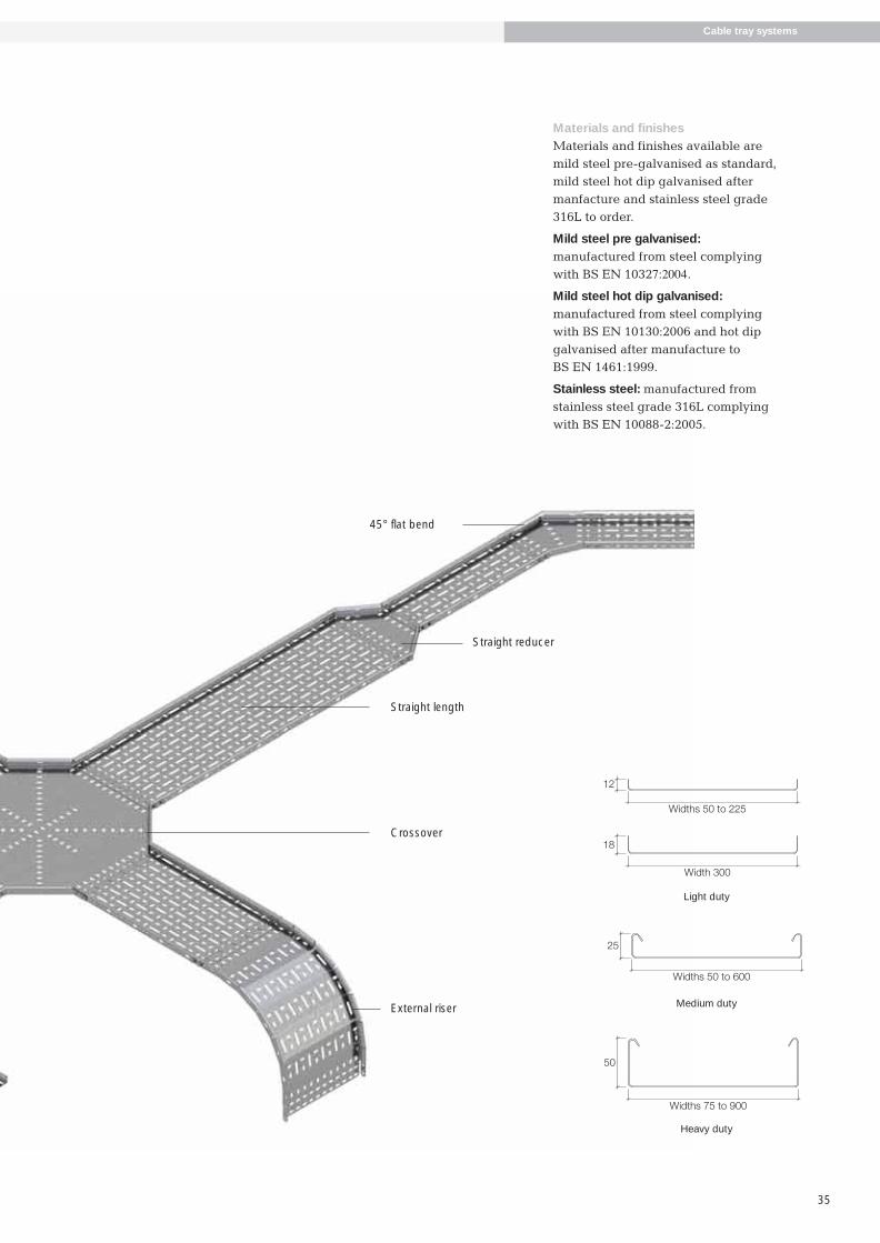
The comprehensive Metstrut cable tray rangeconsists of three systems ranging from the lightduty non-return flange cable tray to twosystems with cable-friendly return flange trays,medium duty 25mm deep and heavy duty50mm deep.
The unique perforation pattern allows ease ofattachment of cables with more than adequateventilation. The side walls of the medium andheavy duty ranges are also slotted as standard.
Light duty cable trays are available in widths of50, 75, 100, 150, 225 and 300mm. Medium dutytrays are available in widths of 50, 75, 100,150,225, 300, 450 and 600mm. Heavy duty trays areavailable in widths of 75, 100, 150, 225, 300,450, 600, 750 and 900mm wide.
Each type of tray is a total system with a wideselection of support accessories to providecomprehensive site installation solutions.
Metstrut cable trays are manufactured onsophisticated CNC equipment in a world classmanufacturing cell engaging a high level ofautomation for fast moving items.This allows Metstrut to maintain a very high level of on time in full delivery performance.
Comprehensive stocks of cable trays andaccessories in both pre-galvanised and post hotdip galvanised finish are carried at all times toensure timely delivery.
Development and testingMetstrut cable tray systems have been fullytested to develop accurate loading graphs.Further verification tests have also been doneunder the requirements of BS EN 61537:2007 –Cable management – cable tray systems andcable ladder systems. These tests includeimpact resistance, marking, connection of re-usable components, safe working load tests,electrical continuity, and performance of steel atextreme temperature ranges.
Metstrut cable tray systems have beendeveloped after significant consultation withmajor installers. This ensures the systems meetand surpass key requirements providinginnovative and cost effective solutions in anincreasingly demanding market
486.5 Metstrut final-04:Layout 1 17/4/09 10:35 Page 32

33
Cable tray systems
Loading graphsSafe working loads are represented graphically as shownand are based on the cable tray being continuous overfour spans or more. Deflection has been limited toSPAN/200 generally, based on the end span condition asthe worst case. Deflection will be less than this on internalspans. However, on wider trays, additional deflection willbe induced locally across the base of the tray, dependingon the width of the tray and the load distribution acrossthe width. This will not be detrimental to the structuralperformance of the tray but may need consideration ifappearance is of prime importance.
Bespoke systemsIn addition to standard cable tray systems, Metstrut hasthe ability to manufacture non standard cable tray systemsto order.
Due to sophisticated equipment and software, prototypescan be produced quickly for sample approval.
It is important for customers to issue the complete order atthe outset to allow full use of materials and avoidexpensive waste.
140
160
120
100
80
60
40
20
0
SPAN m 1.75 21 1.25 1.5
300/600 wide150/225 wide50/100 wide
SA
FE W
OR
KIN
G L
OA
D k
g.p
er m
.
Return flange - medium duty
SPAN m
180
140
160
120
100
80
60
40
20
02.25 2.51.5 1.75 2
450/600 wide225/300 wide75/150 wide
SA
FE W
OR
KIN
G L
OA
D k
g.p
er m
.
Return flange - heavy duty
SPAN m
300
250
200
150
100
50
00.5 0.75 1 1.25 1.5
300 wide50/225 wide
SA
FE W
OR
KIN
G L
OA
D k
g.p
er m
.
Non-return flange - light duty
486.5 Metstrut final-04:Layout 1 17/4/09 10:35 Page 33

Cable tray systems
34
System configuration and supportMetstrut cable trays are designed as a completesystem with simple accessories. Integralconnectors are included for bends tees etc. forall cable tray ranges.
When installing Metstrut cable trays careshould be taken to ensure accessories
Technical construction detailsMedium and heavy duty cable traysystems have cable-friendly returnflanges that are also slotted for allwidths as standard. The uniqueperforation pattern in the base of thecable trays allows ease of attachmentfor cables with more than adequateventilation. All Metstrut cable trayranges have the same plan footprintthat facilitates the set out of cable runsprior to finalisation of design.
DB illus here
39.0
8.0
15.0
15.039.0
8.0
8.0
Equal tee
Straight length
Internal riser
90° flat bend
90° flat bend
Straight length
Straight length
Straight length
Cable tray systems
(e.g. bends, tees, crossovers etc.) have adequatesupport with additional supports for largercomponents. Light duty cable tray straightshave one end swaged for easy connection to thenext tray. When light duty straight trays are cutto smaller lengths on site connection to the nexttray requires a fishplate.
486.5 Metstrut final-04:Layout 1 17/4/09 10:35 Page 34
35
Widths 50 to 225
12
Width 300
18
Widths 50 to 600
25
Widths 75 to 900
50
Straight reducer
45° flat bend
Straight length
External riser
Crossover
Cable tray systems
Materials and finishesMaterials and finishes available aremild steel pre-galvanised as standard,mild steel hot dip galvanised aftermanfacture and stainless steel grade316L to order.
Mild steel pre galvanised:manufactured from steel complyingwith BS EN 10327:2004.
Mild steel hot dip galvanised:manufactured from steel complyingwith BS EN 10130:2006 and hot dipgalvanised after manufacture to BS EN 1461:1999.
Stainless steel: manufactured fromstainless steel grade 316L complyingwith BS EN 10088-2:2005.
Light duty
Medium duty
Heavy duty
486.5 Metstrut final-04:Layout 1 17/4/09 10:35 Page 35

36
StandardsCable tray systems
Metstrut Cable Tray Systems generally conform to BS EN 61537:2007 Cable management - cable traysystems and cable ladder systems.
Information relating to compliance is detailed/highlightedwithin the following sections of the standard:
6 Classification6.1 According to material6.1.1 Metstrut cable tray systems are metallic systemcomponents
6.2 According to resistance to flame propagation6.2.2 Metstrut cable tray systems are non-flamepropagating system components
6.3 According to electrical continuity characteristics6.3.2 Metstrut cable tray systems have electrical continuitycharacteristics
6.4 According to electrical conductivity6.4.1 Metstrut cable tray systems are electricallyconductive system components
6.5 According to resistance against corrosion6.5.2 Metstrut cable tray systems are made of steel withmetallic finishes or stainless steel
(Resistance to corrosion is classified according to Table1 and follow the relevant specification in Table 8, withcompliance according to Table 7.)
Table 1 - classification for resistance against corrosionClass Reference - material and finish
0 (a) None
1 Electroplated to a minimum thickness of 5 µm
2 Electroplated to a minimum thickness of 12 µm
3 Pre - galvanised to grade 275 to EN 10327 and EN 10326
4 Pre - galvanised to grade 350 to EN 10327 and EN 10326
5 Post - galvanised to a zinc mean coating thickness (minimum) of 45 µm according to ISO 1461 for zinc thickness only
6 Post - galvanised to a zinc mean coating thickness (minimum) of 55 µm according to ISO 1461 for zinc thickness only
7 Post - galvanised to a zinc mean coating thickness (minimum) of 70 µm according to ISO 1461 for zinc thickness only
8 Post - galvanised to a zinc mean coating thickness (minimum) of 85 µm according to ISO 1461 for zinc thickness only
9A Stainless steel manufactured to ASTM: A 240/A 240M - 95a designation S30400 or EN 10088 grade 1 - 4301 without a post treatment (b)
9B Stainless steel manufactured to ASTM: A 240/A 240M - 95a designation S31603 or EN 10088 grade 1 - 4404 without a post treatment (b)
9C Stainless steel manufactured to ASTM: A 240/A 240M - 95a designation S30400 or EN 10088 grade 1 - 4301 with a post treatment (b)
9D Stainless steel manufactured to ASTM: A 240/A 240M - 95a designation S31603 or EN 10088 grade 1 - 4404 with a post treatment (b)
(a) For materials which have no declared corrosion resistance classification
(b) The post-treatment process is used to improve the protection against crevice crack corrosion and the contamination by other steels
Table 7 - System component compliance and classification forresistance against corrosionSystem component Classification Compliance Subclause forMaterial and finishes according to compliance check
Non - metallic 6.5.1 Declaration 14.2.1
Reference - 6.5.2 Table 1 Declaration 14.2.2zinc coating classes 1 to 8 or measurementas in Table 1.
Non - referenced zinc 6.5.2 Table 1 By neutral salt 14.2.3coating classes 1 to 8 spray test NSS
Reference - stainless 6.5.2 Table 1 Declaration 14.2.2steel as in Table 1. Class 9A to 9D
Non-referenced Not classified Declaration Nonestainless steel
Other metallic coatings 6.5.2 Table 1 By neutral salt 14.2.3Column 1 classes spray test NSS1 to 8
Aluminium alloys or other 6.5.3 Under Under 14.2.4metals consideration consideration
Organic coatings 6.5.4 Under Under 14.2.5consideration consideration
Table 8 - Zinc coating thickness of referencematerialsClass Minimum Minimum coating Mean coating
Thickness thickness as given in thickness (minimum)EN 10327 or EN 10326 to ISO 1461
µm µm µm
0 (a) - - -1 5 - -2 12 - -3 - 15 -4 - 19 -5 - - 456 - - 557 - - 708 - - 85
(a) As declared by the manufacturer or responsible vendor
486.5 Metstrut final-04:Layout 1 17/4/09 10:35 Page 36

37
Cable tray systems
6.6 According to temperature6.6.1 Minimum temperature for the system components isgiven in Table 2.6.6.2 Maximum temperature for the system components isgiven in Table 3.
6.7 According to the free base area of the cable tray lengthas given in Table 4.
Table 2 - Minimum
temperature classificationMinimum transport, storageinstallation and applicationtemperature °C
+5- 5
- 15- 20- 40- 50
Table 4 - Perforation base classificationClassification Perforation in the base area
A Up to 2%B Over 2% and up to 15%C Over 15% and up to 30%D More than 30%
Note: Classification D relates to IEC 60364 - 5 - 52 Subclause A.52.6.2second paragraph
Table 3 - Maximum
temperature classificationMaximum transport, storageinstallation and applicationtemperature °C
+40+60+90
+105+120+150
6.9 According to impact resistance6.9.4 System component offering impact resistance up to20 J (as verified by testing in accordance with 10.9 Test forimpact resistance.)
7 Marking and documentation7.1 Each system component is marked by a label. Labelsused fully comply with the rubbing test. Boxed items arelabelled on the packaging
8 Dimensions
Key cross sectional dimensions for straight cable trays
Part No. External Internal External Internal X-sectional Gaugedepth mm depth mm width mm width mm area mm2 mm
(Internal)
CTSL12/0050# 12 11.1 50 48.2 535 0.9CTSL12/0075# 12 11.1 75 73.2 813 0.9CTSL12/0100# 12 11.1 100 98.2 1090 0.9CTSL12/0150# 12 11.1 150 148.2 1645 0.9CTSL12/0225# 12 11.1 225 223.2 2478 0.9CTSL18/0300# 18 16.8 300 297.6 5000 1.2CTSL25/0050# 25 24.3 50 48.6 1181 0.7CTSL25/0075# 25 24.3 75 73.6 1788 0.7CTSL25/0100# 25 24.3 100 98.6 2396 0.7CTSL25/0150# 25 24.1 150 148.2 3572 0.9CTSL25/0225# 25 24.1 225 223.2 5379 0.9CTSL25/0300# 25 24.0 300 298.0 7152 1.0CTSL25/0450# 25 23.8 450 447.6 10653 1.2CTSL25/0600# 25 23.8 600 597.6 14223 1.2CTSL50/0075# 50 49.2 75 73.4 3611 0.8CTSL50/0100# 50 49.2 100 98.4 4841 0.8CTSL50/0150# 50 49.1 150 148.2 7277 0.9CTSL50/0225# 50 48.8 225 222.6 10863 1.2CTSL50/0300# 50 48.8 300 297.6 14523 1.2CTSL50/0450# 50 48.5 450 447.0 21680 1.5CTSL50/0600# 50 48.5 600 597.0 28955 1.5CTSL50/0750# 50 48.0 750 746.0 35808 2.0CTSL50/0900# 50 48.0 900 896.0 43008 2.0
Minimum internal radius of fittingsMinimal internal radius of fittings available for theaccommodation of cables is 125mm.
9 Construction9.1 Surfaces of system components which are likely tocome into contact with cables during installation areinspected to ensure they shall not cause damage to thecables when installed correctly.9.2 As with all metallic system components, care should beexercised that handling is in accordance with the relativeCOSHH regulations and gloves should be worn.9.3 Screwed connections have been designed to withstandthe mechanical stresses occurring during installations andnormal use and will not cause damage to cables whencorrectly inserted. Screwed connections are in general ISOmetric threads fully compliant to tests in accordance with9.3.1 and 9.3.2 of the standard. Metstrut cable tray systemsare usually assembled using M6 roofing bolts particularlyfor couplers, fishplates and connection to supportingframework. These bolts should be tightened to a torque of12N/m.
10 Mechanical propertiesCable tray lengths have been tested generally inaccordance with the standard under 10.2 and 10.3 forverification of the loading graphs. It should be noted thatindependent testing has been carried out to verify thestructural performance of the cable trays at the minimumand maximum temperature classifications for testconditions under 10.2.2.
All accessories eg bends, tees etc should be directlysupported by a suitable support device or devices atappropriate positions.
486.5 Metstrut final-04:Layout 1 17/4/09 10:35 Page 37

Cable tray systems
38
Product footprint
Length 1 = Width + radius
Radius
Radius
Radius
100
Width
Width 1 Width 2
Radius250mm
Radius
Length 2 = width + 2 x radius
Width Radius
Width
Radius
Width
Radius
Length 1 = width 1 + radius
Width 2
Radius
250m
m
Radius
Radius
Radius
Length 2 = width 2 + 2 x radius
Length = width + 2 x radius
Width
Length = width + 2 x radius
Radius
Width
Width 1
Radius
Radius
Radius
100
width 2Width 1
Length = width+ radius
Length = width + radius
Radius
RadiusRadius
Radius
90º flat bend Crossover
Equal tee Unequal tee
90º riser Straight or right / left hand reducer
Cable tray systems
Footprints are identical for all ranges
Cable tray — accessory foot printStandard radius is 125mm
486.5 Metstrut final-04:Layout 1 17/4/09 10:35 Page 38

39
Length 1 = Width + radius
Radius
100
Width 1 Width 2
Radius
Width
Radius
Width
Radius
Length 1 = width 1 + radius
Width 2Radius
Radius
Radius
Length 2 = width 2 + 2 x radius
Length = width + 2 x radius
Width
Length = width + 2 x radius
Radius
Width
Width 1
Radius
Radius
Radius
100
width 2Width 1
Length = width+ radius
RadiusRadius
Crossover
Unequal tee
Straight or right / left hand reducer
Straight length
Finish: pre galvanised = PG, post galvanised = HDG, stainless steel grade 316 = SS
Width Light duty Medium duty Heavy dutymm
50 CTSL12/0050PG3 CTSL25/0050PG3 N/A
75 CTSL12/0075PG3 CTSL25/0075PG3 CTSL50/0075PG3
100 CTSL12/0100PG3 CTSL25/0100PG3 CTSL50/0100PG3
150 CTSL12/0150PG3 CTSL25/0150PG3 CTSL50/0150PG3
225 CTSL12/0225PG3 CTSL25/0225PG3 CTSL50/0225PG3
300 CTSL18/0300PG3 CTSL25/0300PG3 CTSL50/0300PG3
450 N/A CTSL25/0450PG3 CTSL50/0450PG3
600 N/A CTSL25/0600PG3 CTSL50/0600PG3
750 N/A N/A CTSL50/0750PG3
900 N/A N/A CTSL50/0900PG3
Medium duty straight couplers
Only required for straight tray to straight tray connection – medium duty rangeFinish: post galvanised = HDG, stainless steel grade 316 = SS
Sold in pairs (fasteners excluded)
CTSC25HDGPR
Not available in pre galvanised
Medium duty wrap over couplers
Only required for straight tray to straight tray connection – medium duty rangeFinish: pre galvanised = PG, post galvanised = HDG, stainless steel grade 316 = SS
Sold in pairs (fasteners excluded)
CTC25PGPR
Heavy duty straight couplers
Only required for straight tray to straight tray connection – heavy duty rangeFinish: post galvanised = HDG, stainless steel grade 316 = SS
Sold in pairs (fasteners excluded)
CTSC50HDGPR
Not available in pre galvanised
Heavy duty wrap over couplers
Only required for straight tray to straight tray connection – heavy duty rangeFinish: pre galvanised = PG, post galvanised = HDG, stainless steel grade 316 = SS
Sold in pairs (fasteners excluded)
CTC50PGPR
Cable tray systems
486.5 Metstrut final-04:Layout 1 17/4/09 10:35 Page 39

Cable tray systems
40
90º flat bends
Finish: pre galvanised = PG, post galvanised = HDG, stainless steel grade 316 = SS
Width Light duty Medium duty Heavy dutymm
50 CTFB12/0050PG90 CTFB25/0050PG90 N/A
75 CTFB12/0075PG90 CTFB25/0075PG90 CTFB50/0075PG90
100 CTFB12/0100PG90 CTFB25/0100PG90 CTFB50/0100PG90
150 CTFB12/0150PG90 CTFB25/0150PG90 CTFB50/0150PG90
225 CTFB12/0225PG90 CTFB25/0225PG90 CTFB50/0225PG90
300 CTFB18/0300PG90 CTFB25/0300PG90 CTFB50/0300PG90
450 N/A CTFB25/0450PG90 CTFB50/0450PG90
600 N/A CTFB25/0600PG90 CTFB50/0600PG90
750 N/A N/A CTFB50/0750PG90
900 N/A N/A CTFB50/0900PG90
45º flat bends
Finish: pre galvanised = PG, post galvanised = HDG, stainless steel grade 316 = SS
Width Light duty Medium duty Heavy dutymm
50 CTFB12/0050PG45 CTFB25/0050PG45 N/A
75 CTFB12/0075PG45 CTFB25/0075PG45 CTFB50/0075PG45
100 CTFB12/0100PG45 CTFB25/0100PG45 CTFB50/0100PG45
150 CTFB12/0150PG45 CTFB25/0150PG45 CTFB50/0150PG45
225 CTFB12/0225PG45 CTFB25/0225PG45 CTFB50/0225PG45
300 CTFB18/0300PG45 CTFB25/0300PG45 CTFB50/0300PG45
450 N/A CTFB25/0450PG45 CTFB50/0450PG45
600 N/A CTFB25/0600PG45 CTFB50/0600PG45
750 N/A N/A CTFB50/0750PG45
900 N/A N/A CTFB50/0900PG45
Adjustable flat bends
(Not available for light duty cable tray)Finish: pre galvanised = PG, post galvanised = HDG, stainless steel grade 316 = SS
Width Medium duty Heavy dutymm
50 CTAB25/0050PG N/A
75 CTAB25/0075PG CTAB50/0075PG
100 CTAB25/0100PG CTAB50/0100PG
150 CTAB25/0150PG CTAB50/0150PG
225 CTAB25/0225PG CTAB50/0225PG
300 CTAB25/0300PG CTAB50/0300PG
Equal tee
Finish: pre galvanised = PG, post galvanised = HDG, stainless steel grade 316 = SS
Width Light duty Medium duty Heavy dutymm
50 CTET12/0050PG CTET25/0050PG N/A
75 CTET12/0075PG CTET25/0075PG CTET50/0075PG
100 CTET12/0100PG CTET25/0100PG CTET50/0100PG
150 CTET12/0150PG CTET25/0150PG CTET50/0150PG
225 CTET12/0225PG CTET25/0225PG CTET50/0225PG
300 CTET18/0300PG CTET25/0300PG CTET50/0300PG
450 N/A CTET25/0450PG CTET50/0450PG
600 N/A CTET25/0600PG CTET50/0600PG
750 N/A N/A CTET50/0750PG
900 N/A N/A CTET50/0900PG
Cable tray systems
486.5 Metstrut final-04:Layout 1 17/4/09 10:35 Page 40

41
Unequal tee (made to order)
Finish: pre galvanised = PG, post galvanised = HDG, stainless steel grade 316 = SS
Cable tray systems
W1
W2
How to generate the part number - CTUT (depth)/W1/W2(finish)Example - CTUT 25/0300/0150/PGTable below shows a complete list of W1 and W2 combinations.
W1 W2 W1 W2 W1 W2 W1 W2
50 75 100 450 300 75 600 450
50 100 100 600 300 100 600 750
50 150 100 750 300 150 600 900
50 225 100 900 300 225 750 50
50 300 150 50 300 450 750 75
50 450 150 75 300 600 750 100
50 600 150 100 300 750 750 150
50 750 150 225 300 900 750 225
50 900 150 300 450 50 750 300
75 50 150 450 450 75 750 450
75 100 150 600 450 100 750 600
75 150 150 750 450 150 750 900
75 225 150 900 450 225 900 50
75 300 225 50 450 300 900 75
75 450 225 75 450 600 900 100
75 600 225 100 450 750 900 150
75 750 225 150 450 900 900 225
75 900 225 300 600 50 900 300
100 50 225 450 600 75 900 450
100 75 225 600 600 100 900 600
100 150 225 750 600 150 900 750
100 225 225 900 600 225
100 300 300 50 600 300
486.5 Metstrut final-04:Layout 1 17/4/09 10:35 Page 41

Cable tray systems
42
Crossovers
Finish: pre galvanised = PG, post galvanised = HDG, stainless steel grade 316 = SS
Width Light duty Medium duty Heavy dutymm
50 CTCO12/0050PG CTCO25/0050PG N/A
75 CTCO12/0075PG CTCO25/0075PG CTCO50/0075PG
100 CTCO12/0100PG CTCO25/0100PG CTCO50/0100PG
150 CTCO12/0150PG CTCO25/0150PG CTCO50/0150PG
225 CTCO12/0225PG CTCO25/0225PG CTCO50/0225PG
300 CTCO18/0300PG CTCO25/0300PG CTCO50/0300PG
450 N/A CTCO25/0450PG CTCO50/0450PG
600 N/A CTCO25/0600PG CTCO50/0600PG
750 N/A N/A CTCO50/0750PG
900 N/A N/A CTCO50/0900PG
Internal riser - flexible
Finish: pre galvanised = PG, post galvanised = HDG, stainless steel grade 316 = SSCTFR = Flexible risers are supplied flat and folded on site to suit angle.CTIR = Internal risers are folded to suit stated angle. 90 = 90°, 60 = 60°, 45 = 45°, 30 = 30°Eg: CTIR50/0900PG90
Width Light duty Medium duty Heavy dutymm
50 CTFR12/0050PG CTFR25/0050PG N/A
75 CTFR12/0075PG CTFR25/0075PG CTFR50/0075PG
100 CTFR12/0100PG CTFR25/0100PG CTFR50/0100PG
150 CTFR12/0150PG CTFR25/0150PG CTFR50/0150PG
225 CTFR12/0225PG CTFR25/0225PG CTFR50/0225PG
300 CTFR18/0300PG CTFR25/0300PG CTFR50/0300PG
450 N/A CTFR25/0450PG CTFR50/0450PG
600 N/A CTFR25/0600PG CTFR50/0600PG
750 N/A N/A CTIR50/0750PG90 (only available pre-folded)
900 N/A N/A CTIR50/0900PG90 (only available pre-folded)
External riser - flexible
Finish: pre galvanised = PG, post galvanised = HDG, stainless steel grade 316 = SSCTFR = Flexible risers are supplied flat and folded on site to suit angle.CTER = External risers are folded to suit stated angle. 90 = 90°, 60 = 60°, 45 = 45°, 30 = 30°Eg: CTER50/0900PG90
Width Light duty Medium duty Heavy dutymm
50 CTFR12/0050PG CTFR25/0050PG N/A
75 CTFR12/0075PG CTFR25/0075PG CTFR50/0075PG
100 CTFR12/0100PG CTFR25/0100PG CTFR50/0100PG
150 CTFR12/0150PG CTFR25/0150PG CTFR50/0150PG
225 CTFR12/0225PG CTFR25/0225PG CTFR50/0225PG
300 CTFR18/0300PG CTFR25/0300PG CTFR50/0300PG
450 N/A CTFR25/0450PG CTFR50/0450PG
600 N/A CTFR25/0600PG CTFR50/0600PG
750 N/A N/A CTER50/0750PG90 (only available pre-folded)
900 N/A N/A CTER50/0900PG90 (only available pre-folded)
Cable tray systems
486.5 Metstrut final-04:Layout 1 17/4/09 10:35 Page 42

43
Reducers
Finish: pre galvanised = PG, post galvanised = HDG, stainless steel grade 316 = SS
Width Light duty Medium duty Heavy dutymmW1 W2
75 50 CTSR12/0075/0050PG CTSR25/0075/0050PG N/A
100 50 CTSR12/0100/0050PG CTSR25/0100/0050PG N/A
150 50 CTSR12/0150/0050PG CTSR25/0150/0050PG N/A
225 50 CTSR12/0225/0050PG CTSR25/0225/0050PG N/A
300 50 CTSR18/0300/0050PG CTSR25/0300/0050PG N/A
450 50 N/A CTSR25/0450/0050PG N/A
600 50 N/A CTSR25/0600/0050PG N/A
750 50 N/A N/A N/A
900 50 N/A N/A N/A
100 75 CTSR12/0100/0075PG CTSR25/0100/0075PG CTSR50/0100/0075PG
150 75 CTSR12/0150/0075PG CTSR25/0150/0075PG CTSR50/0150/0075PG
225 75 CTSR12/0225/0075PG CTSR25/0225/0075PG CTSR50/0225/0075PG
300 75 CTSR18/0300/0075PG CTSR25/0300/0075PG CTSR50/0300/0075PG
450 75 N/A CTSR25/0450/0075PG CTSR50/0450/0075PG
600 75 N/A CTSR25/0600/0075PG CTSR50/0600/0075PG
750 75 N/A N/A CTSR50/0750/0075PG
900 75 N/A N/A CTSR50/0900/0075PG
150 100 CTSR12/0150/0100PG CTSR25/0150/0100PG CTSR50/0150/0100PG
225 100 CTSR12/0225/0100PG CTSR25/0225/0100PG CTSR50/0225/0100PG
300 100 CTSR18/0300/0100PG CTSR25/0300/0100PG CTSR50/0300/0100PG
450 100 N/A CTSR25/0450/0100PG CTSR50/0450/0100PG
600 100 N/A CTSR25/0600/0100PG CTSR50/0600/0100PG
750 100 N/A N/A CTSR50/0750/0100PG
900 100 N/A N/A CTSR50/0900/0100PG
225 150 CTSR12/0225/0150PG CTSR25/0225/0150PG CTSR50/0225/0150PG
300 150 CTSR18/0300/0150PG CTSR25/0300/0150PG CTSR50/0300/0150PG
450 150 N/A CTSR25/0450/0150PG CTSR50/0450/0150PG
600 150 N/A CTSR25/0600/0150PG CTSR50/0600/0150PG
750 150 N/A N/A CTSR50/0750/0150PG
900 150 N/A N/A CTSR50/0900/0150PG
300 225 CTSR18/0300/0225PG CTSR25/0300/0225PG CTSR50/0300/0225PG
450 225 N/A CTSR25/0450/0225PG CTSR50/0450/0225PG
600 225 N/A CTSR25/0600/0225PG CTSR50/0600/0225PG
750 225 N/A N/A CTSR50/0750/0225PG
900 225 N/A N/A CTSR50/0900/0225PG
450 300 N/A CTSR25/0450/0300PG CTSR50/0450/0300PG
600 300 N/A CTSR25/0600/0300PG CTSR50/0600/0300PG
750 300 N/A N/A CTSR50/0750/0300PG
900 300 N/A N/A CTSR50/0900/0300PG
600 450 N/A CTSR25/0600/0450PG CTSR50/0600/0450PG
750 450 N/A N/A CTSR50/0750/0450PG
900 450 N/A N/A CTSR50/0900/0450PG
750 600 N/A N/A CTSR50/0750/0600PG
900 600 N/A N/A CTSR50/0900/0600PG
900 750 N/A N/A CTSR50/0900/0750PG
Cable tray systems
W1
W2
486.5 Metstrut final-04:Layout 1 17/4/09 10:35 Page 43

Cable tray systems
44
Fishplate couplers
Finish: pre galvanised = PG, post galvanised = HDG, stainless steel grade 316 = SS
Widthmm (always required for cut lengths of light duty tray)
50 CTFP1PG
75 CTFP1PG
100 CTFP1PG
150 CTFP1PG
225 CTFP2PG
300 CTFP2PG
450 CTFP2PG
600 CTFP2PG
750 CTFP2PG
900 CTFP2PG
Cover - straight length - 3m long
Finish: pre galvanised = PG, post galvanised = HDG, stainless steel grade 316 = SSStandard closed covers = CC, ventilated cover = CVIncludes 6 fixing clamps and fasteners
Width Light duty Medium duty Heavy duty
50 CTSL12CV/050PG CTSL25CC/050PG N/A
75 CTSL12CV/075PG CTSL25CC/075PG CTSL50CC/075PG
100 CTSL12CV/100PG CTSL25CC/100PG CTSL50CC/100PG
150 CTSL12CV/150PG CTSL25CC/150PG CTSL50CC/150PG
225 CTSL12CV/225PG CTSL25CC/225PG CTSL50CC/225PG
300 CTSL18CV/300PG CTSL25CC/300PG CTSL50CC/300PG
450 N/A CTSL25CC/450PG CTSL50CC/450PG
600 N/A CTSL25CC/600PG CTSL50CC/600PG
750 N/A N/A CTSL50CC/750PG
900 N/A N/A CTSL50CC/900PG
*NB. Closed cover not available for 12mm and 18mm deep cable tray.
Cover - 90º flat bends
Finish: pre galvanised = PG, post galvanised = HDG, stainless steel grade 316 = SSStandard closed covers = CC, ventilated cover = CVIncludes 5 fixing clamps and fasteners
Width Light duty Medium duty Heavy duty
50 CTFB12CV/050PG90 CTFB25CC/050PG90 N/A
75 CTFB12CV/075PG90 CTFB25CC/075PG90 CTFB50CC/075PG90
100 CTFB12CV/100PG90 CTFB25CC/100PG90 CTFB50CC/100PG90
150 CTFB12CV/150PG90 CTFB25CC/150PG90 CTFB50CC/150PG90
225 CTFB12CV/225PG90 CTFB25CC/225PG90 CTFB50CC/225PG90
300 CTFB18CV/300PG90 CTFB25CC/300PG90 CTFB50CC/300PG90
450 N/A CTFB25CC/450PG90 CTFB50CC/450PG90
600 N/A CTFB25CC/600PG90 CTFB50CC/600PG90
750 N/A N/A CTFB50CC/750PG90
900 N/A N/A CTFB50CC/900PG90
*NB. Closed cover not available for 12mm and 18mm deep cable tray.
Extra cover clips
Finish: pre galvanised = PG, post galvanised = HDG, stainless steel grade 316 = SSStandard closed covers = CC, ventilated cover = CV
Duty Standard Ventilated
Light N/A CTCCV18HDG
Medium CTCCC25HDG CTCCV25HDG
Heavy CTCCC50HDG CTCCV50HDG
Cable tray systems
486.5 Metstrut final-04:Layout 1 17/4/09 10:35 Page 44

45
Cover - 45º flat bends
Finish: pre galvanised = PG, post galvanised = HDG, stainless steel grade 316 = SSStandard closed covers = CC, ventilated cover = CVIncludes 5 fixing clamps and fasteners
Width Light duty Medium duty Heavy duty
50 CTFB12CV/050PG45 CTFB25CC/050PG45 N/A
75 CTFB12CV/075PG45 CTFB25CC/075PG45 CTFB50CC/075PG45
100 CTFB12CV/100PG45 CTFB25CC/100PG45 CTFB50CC/100PG45
150 CTFB12CV/150PG45 CTFB25CC/150PG45 CTFB50CC/150PG45
225 CTFB12CV/225PG45 CTFB25CC/225PG45 CTFB50CC/225PG45
300 CTFB18CV/300PG45 CTFB25CC/300PG45 CTFB50CC/300PG45
450 N/A CTFB25CC/450PG45 CTFB50CC/450PG45
600 N/A CTFB25CC/600PG45 CTFB50CC/600PG45
750 N/A N/A CTFB50CC/750PG45
900 N/A N/A CTFB50CC/900PG45
*NB. Closed cover not available for 12mm and 18mm deep cable tray.
Cover - crossover
Finish: pre galvanised = PG, post galvanised = HDG, stainless steel grade 316 = SSStandard closed covers = CC, ventilated cover = CVIncludes 4 fixing clamps and fasteners
Width Light duty Medium duty Heavy duty
50 CTCO12CV/050PG CTCO25CC/050PG N/A
75 CTCO12CV/075PG CTCO25CC/075PG CTCO50CC/075PG
100 CTCO12CV/100PG CTCO25CC/100PG CTCO50CC/100PG
150 CTCO12CV/150PG CTCO25CC/150PG CTCO50CC/150PG
225 CTCO12CV/225PG CTCO25CC/225PG CTCO50CC/225PG
300 CTCO18CV/300PG CTCO25CC/300PG CTCO50CC/300PG
450 N/A CTCO25CC/450PG CTCO50CC/450PG
600 N/A CTCO25CC/600PG CTCO50CC/600PG
750 N/A N/A CTCO50CC/750PG
900 N/A N/A CTCO50CC/900PG
*NB. Closed cover not available for 12mm and 18mm deep cable tray.
Cover - equal tee
Finish: pre galvanised = PG, post galvanised = HDG, stainless steel grade 316 = SSStandard closed covers = CC, ventilated cover = CVIncludes 5 fixing clamps and fasteners
Width Light duty Medium duty Heavy duty
50 CTET12CV/050PG CTET25CC/050PG N/A
75 CTET12CV/075PG CTET25CC/075PG CTET50CC/075PG
100 CTET12CV/100PG CTET25CC/100PG CTET50CC/100PG
150 CTET12CV/150PG CTET25CC/150PG CTET50CC/150PG
225 CTET12CV/225PG CTET25CC/225PG CTET50CC/225PG
300 CTET18CV/300PG CTET25CC/300PG CTET50CC/300PG
450 N/A CTET25CC/450PG CTET50CC/450PG
600 N/A CTET25CC/600PG CTET50CC/600PG
750 N/A N/A CTET50CC/750PG
900 N/A N/A CTET50CC/900PG
*NB. Closed cover not available for 12mm and 18mm deep cable tray.
Cable tray systems
486.5 Metstrut final-04:Layout 1 17/4/09 10:35 Page 45

Cable tray systems
46
Cover - unequal tee (made to order)
Finish: pre galvanised = PG, post galvanised = HDG, stainless steel grade 316 = SSStandard closed covers = CC, ventilated cover = CVIncludes 5 fixing clamps and fasteners
Cable tray systems
W1W2
How to generate the part number - CTUT (cover type) (depth)/W1/W2(finish)Example - CTUT CC 25/300/150PGTable below shows a complete list of W1 and W2 combinations.
W1 W2 W1 W2 W1 W2 W1 W2
50 75 100 450 300 75 600 450
50 100 100 600 300 100 600 750
50 150 100 750 300 150 600 900
50 225 100 900 300 225 750 50
50 300 150 50 300 450 750 75
50 450 150 75 300 600 750 100
50 600 150 100 300 750 750 150
50 750 150 225 300 900 750 225
50 900 150 300 450 50 750 300
75 50 150 450 450 75 750 450
75 100 150 600 450 100 750 600
75 150 150 750 450 150 750 900
75 225 150 900 450 225 900 50
75 300 225 50 450 300 900 75
75 450 225 75 450 600 900 100
75 600 225 100 450 750 900 150
75 750 225 150 450 900 900 225
75 900 225 300 600 50 900 300
100 50 225 450 600 75 900 450
100 75 225 600 600 100 900 600
100 150 225 750 600 150 900 750
100 225 225 900 600 225
100 300 300 50 600 300
*NB. Closed cover not available for 12mm and 18mm deep cable tray.
486.5 Metstrut final-04:Layout 1 17/4/09 10:36 Page 46

47
Cover - reducer
Finish: pre galvanised = PG, post galvanised = HDG, stainless steel grade 316 = SSStandard closed covers = CC, ventilated cover = CVIncludes 4 fixing clamps and fasteners
Width Light duty Medium duty Heavy duty mmW1 W2
75 50 CTSRCV12/0075/0050PG CTSRCC25/0075/0050PG N/A
100 50 CTSRCV12/0100/0050PG CTSRCC25/0100/0050PG N/A
150 50 CTSRCV12/0150/0050PG CTSRCC25/0150/0050PG N/A
225 50 CTSRCV12/0225/0050PG CTSRCC25/0225/0050PG N/A
300 50 N/A CTSRCC25/0300/0050PG N/A
450 50 N/A CTSRCC25/0450/0050PG N/A
600 50 N/A CTSRCC25/0600/0050PG N/A
750 50 N/A N/A N/A
900 50 N/A N/A N/A
100 75 CTSRCV12/0100/0075PG CTSRCC25/0100/0075PG CTSRCC50/0100/0075PG
150 75 CTSRCV12/0150/0075PG CTSRCC25/0150/0075PG CTSRCC50/0150/0075PG
225 75 CTSRCV12/0225/0075PG CTSRCC25/0225/0075PG CTSRCC50/0225/0075PG
300 75 CTSRCV18/0300/0075PG CTSRCC25/0300/0075PG CTSRCC50/0300/0075PG
450 75 N/A CTSRCC25/0450/0075PG CTSRCC50/0450/0075PG
600 75 N/A CTSRCC25/0600/0075PG CTSRCC50/0600/0075PG
750 75 N/A N/A CTSRCC50/0750/0075PG
900 75 N/A N/A CTSRCC50/0900/0075PG
150 100 CTSRCV12/0150/0100PG CTSRCC25/0150/0100PG CTSRCC50/0150/0100PG
225 100 CTSRCV12/0225/0100PG CTSRCC25/0225/0100PG CTSRCC50/0225/0100PG
300 100 CTSRCV18/0300/0100PG CTSRCC25/0300/0100PG CTSRCC50/0300/0100PG
450 100 N/A CTSRCC25/0450/0100PG CTSRCC50/0450/0100PG
600 100 N/A CTSRCC25/0600/0100PG CTSRCC50/0600/0100PG
750 100 N/A N/A CTSRCC50/0750/0100PG
900 100 N/A N/A CTSRCC50/0900/0100PG
225 150 CTSRCV12/0225/0150PG CTSRCC25/0225/0150PG CTSRCC50/0225/0150PG
300 150 CTSRCV18/0300/0150PG CTSRCC25/0300/0150PG CTSRCC50/0300/0150PG
450 150 N/A CTSRCC25/0450/0150PG CTSRCC50/0450/0150PG
600 150 N/A CTSRCC25/0600/0150PG CTSRCC50/0600/0150PG
750 150 N/A N/A CTSRCC50/0750/0150PG
900 150 N/A N/A CTSRCC50/0900/0150PG
300 225 CTSRCV18/0300/0225PG CTSRCC25/0300/0225PG CTSRCC50/0300/0225PG
450 225 N/A CTSRCC25/0450/0225PG CTSRCC50/0450/0225PG
600 225 N/A CTSRCC25/0600/0225PG CTSRCC50/0600/0225PG
750 225 N/A N/A CTSRCC50/0750/0225PG
900 225 N/A N/A CTSRCC50/0900/0225PG
450 300 N/A CTSRCC25/0450/0300PG CTSRCC50/0450/0300PG
600 300 N/A CTSRCC25/0600/0300PG CTSRCC50/0600/0300PG
750 300 N/A N/A CTSRCC50/0750/0300PG
900 300 N/A N/A CTSRCC50/0900/0300PG
600 450 N/A CTSRCC25/0600/0450PG CTSRCC50/0600/0450PG
750 450 N/A N/A CTSRCC50/0750/0450PG
900 450 N/A N/A CTSRCC50/0900/0450PG
750 600 N/A N/A CTSRCC50/0750/0600PG
900 600 N/A N/A CTSRCC50/0900/0600PG
900 750 N/A N/A CTSRCC50/0900/0750PG
*NB. Closed cover not available for 12mm and 18mm deep cable tray.
Cable tray systems
W1
W2
486.5 Metstrut final-04:Layout 1 17/4/09 10:36 Page 47

Cable tray systems
48
Cover - 90º internal riser
Finish: pre galvanised = PG, post galvanised = HDG, stainless steel grade 316 = SSStandard closed covers = CC, ventilated cover = CVIncludes 8 fixing clamps and fasteners
Width Light duty Medium duty Heavy dutymm
50 CTIR12CV/0050PG90 CTIR25CC/0050PG90 N/A
75 CTIR12CV/0075PG90 CTIR25CC/0075PG90 CTIR50CC/0075PG90
100 CTIR12CV/0100PG90 CTIR25CC/0100PG90 CTIR50CC/0100PG90
150 CTIR12CV/0150PG90 CTIR25CC/0150PG90 CTIR50CC/0150PG90
225 CTIR12CV/0225PG90 CTIR25CC/0225PG90 CTIR50CC/0225PG90
300 CTIR18CV/0300PG90 CTIR25CC/0300PG90 CTIR50CC/0300PG90
450 N/A CTIR25CC/0450PG90 CTIR50CC/0450PG90
600 N/A CTIR25CC/0600PG90 CTIR50CC/0600PG90
750 N/A N/A CTIR50CC/0750PG90
900 N/A N/A CTIR50CC/0900PG90
*NB. Closed cover not available for 12mm and 18mm deep cable tray.
Cover - 90º external riser
Finish: pre galvanised = PG, post galvanised = HDG, stainless steel grade 316 = SSStandard closed covers = CC, ventilated cover = CVIncludes 8 fixing clamps and fasteners
Width Light duty Medium duty Heavy dutymm
50 CTER12CV/0050PG90 CTER25CC/0050PG90 N/A
75 CTER12CV/0075PG90 CTER25CC/0075PG90 CTER50CC/0075PG90
100 CTER12CV/0100PG90 CTER25CC/0100PG90 CTER50CC/0100PG90
150 CTER12CV/0150PG90 CTER25CC/0150PG90 CTER50CC/0150PG90
225 CTER12CV/0225PG90 CTER25CC/0225PG90 CTER50CC/0225PG90
300 CTER18CV/0300PG90 CTER25CC/0300PG90 CTER50CC/0300PG90
450 N/A CTER25CC/0450PG90 CTER50CC/0450PG90
600 N/A CTER25CC/0600PG90 CTER50CC/0600PG90
750 N/A N/A CTER50CC/0750PG90
900 N/A N/A CTER50CC/0900PG90
*NB. Closed cover not available for 12mm and 18mm deep cable tray.
Stand off brackets
Finish: pre galvanised = PG, post galvanised = HDG, stainless steel grade 316 = SS
Widthmm
50 CTSO050PG
75 CTSO075PG
100 CTSO100PG
150 CTSO150PG
225 CTSO225PG
300 CTSO300PG
450 CTSO450PG
600 CTSO600PG
750 CTSO750PG
900 CTSO900PG
Cable tray systems
486.5 Metstrut final-04:Layout 1 17/4/09 10:36 Page 48
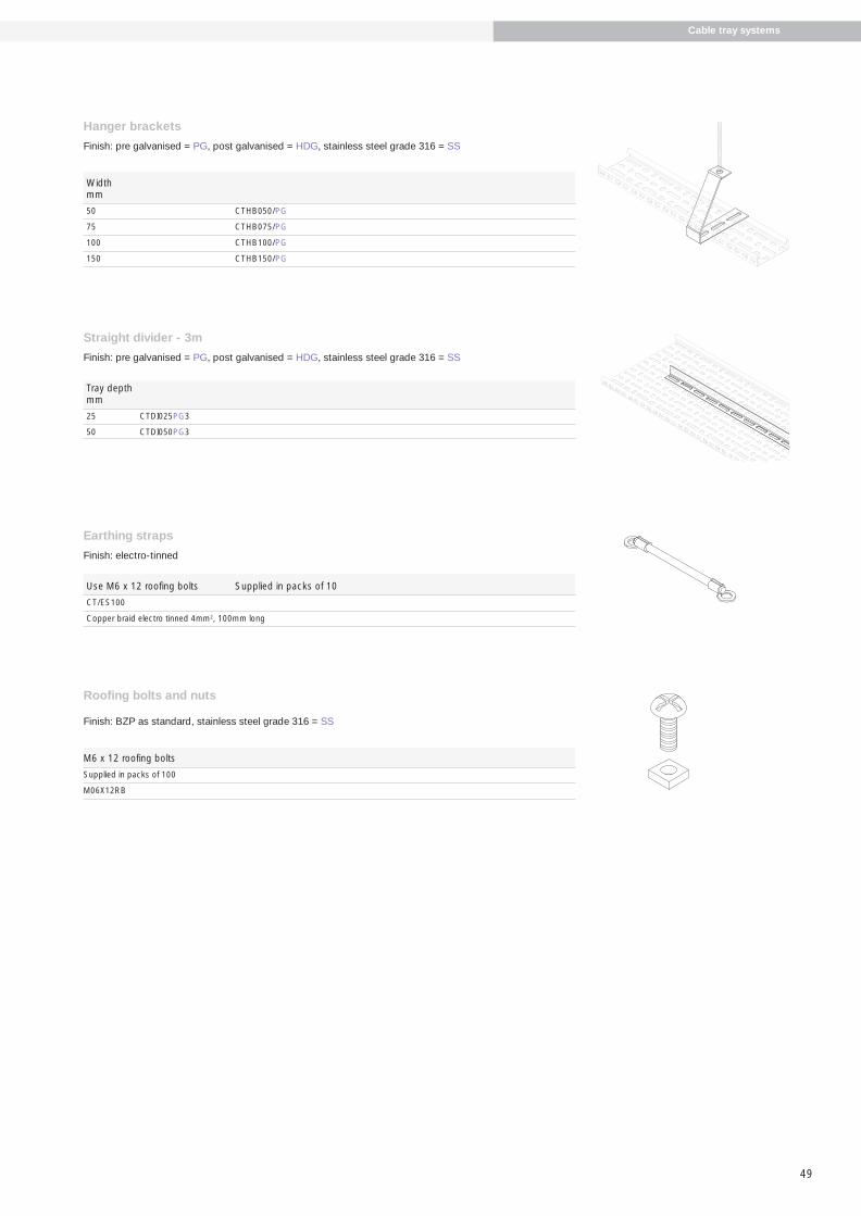
49
Hanger brackets
Finish: pre galvanised = PG, post galvanised = HDG, stainless steel grade 316 = SS
Widthmm
50 CTHB050/PG
75 CTHB075/PG
100 CTHB100/PG
150 CTHB150/PG
Straight divider - 3m
Finish: pre galvanised = PG, post galvanised = HDG, stainless steel grade 316 = SS
Tray depthmm
25 CTDI025PG3
50 CTDI050PG3
Earthing straps
Finish: electro-tinned
Use M6 x 12 roofing bolts Supplied in packs of 10
CT/ES100
Copper braid electro tinned 4mm2, 100mm long
Roofing bolts and nuts
Finish: BZP as standard, stainless steel grade 316 = SS
M6 x 12 roofing bolts
Supplied in packs of 100
M06X12RB
Cable tray systems
486.5 Metstrut final-04:Layout 1 17/4/09 10:36 Page 49

Trunking systems
Cable trunking systems
50
The comprehensive Metstrut cable trunkingranges consist of standard distribution trunkingand lighting trunking.
Standard distribution trunking is available inwidths and depths up to 225mm as standard.Lids are attached by turnbuckle fixings, withScrewfix and tamperproof fixings also available.
Lighting trunking is available in 50mm x 50mmwith straights in various length configurations.This range utilises the Standard distributiontrunking components but with snap on lidsavailable in pre galvanised steel or whiteplastic. This allows flexibility on site whenusing both systems.
Metstrut cable trunking systems aremanufactured on sophisticated CNC equipmentwith a high level of automation for fast movingitems. The fully integrated production processensures Metstrut is able to offer a high level ofservice.
Metstrut cable trunking systems meet therequirements of a demanding electricalinstallations market. Utilising world classproduction methods Metstrut are able tooffer competitive solutions to a high level of service.
Development and testingMetstrut trunking systems have been developed to meet the requirements of BS EN 50085-1: 2005 and BS EN 50085-2-1:2006 Cable trunking systemsand cable ducting systems for electricalinstallations.
486.5 Metstrut final-04:Layout 1 17/4/09 10:36 Page 50

51
Trunking systems
Comprehensive stock, rapid deliveryMetstrut manufactures to lean principles on aKanban system for stock control. This ensures ahigh level of delivery performance is achievedto meet the demanding service requirementsneeded to meet the needs of end users.
Comprehensive stocks are available at all timesand Metstrut has the ability to turn around non-standard applications quickly due to thesophisticated manufacturing processesemployed. The virtual factory software used inthe manufacturing process provides acontinuous monitoring tool for stocks, work inprogress and replenishment times.
486.5 Metstrut final-04:Layout 1 17/4/09 10:36 Page 51

Cable trunking systems
52
System configuration and supportMetstrut cable trunking systems aredesigned as a complete system with a rangeof easy fit accessories. Integral connectors areincluded for all fittings as well as fixing bolts.These connectors include pre tapped holesavoiding the need for nuts and washers.Trunking straight lengths come completewith coupler and fixing screws.
Metstrut lighting trunking utilises the sameaccessories as the standard trunking range,but straight bodies are available in numerouslength configurations. Clip on lids areavailable for this range in both metalgalvanised or white plastic.
Technical construction detailsMetstrut standard trunking systemsincorporate lids connected by turnbucklefasteners pre assembled. This almost flushfixing with its cross head allows easyinstallation or removal with conventionalcross/flat blade screwdrivers. Alternativefixings are available to order includingscrewfix and tamperproof screws
Flared coupler
90° top lid bend square
Straight length
Straight length
Tee top lid
Trunking systems
Turnbuckle typee.g. TTT/100/100/PG/G
Screwfix type - add “S” after the first Te.g. TSTT/100/100/PG/G
Tamperproof type - add “M” after the first Te.g. TMTT/100/100/PG/G
486.5 Metstrut final-04:Layout 1 17/4/09 10:36 Page 52

53
Straight length
90° inside lid bend
90° top lid bend
45° inside lid bend
Reducer
Crossover
Trunking systems
Materials and finishesMaterials and finishes available are mildsteel pre galvanised as standard and powdercoated to order.
Mild steel pre galvanised: manufactured fromsteel complying with BS EN 10327:2004.
486.5 Metstrut final-04:Layout 1 17/4/09 10:36 Page 53

54
StandardsTrunking systems
Metstrut Cable Trunking Systems generally conform to BS EN 50085-1:2005 Cable trunking systems and cableducting systems for electrical installations-Part 1: Generalrequirements, and BS EN 50085-2-1:2006 Cable trunkingsystems and cable ducting systems for electricalinstallations-Part 2-1: Cable trunking systems and cableducting systems intended for mounting on walls andceilings.
The above supercedes BS 4678, now withdrawn.
This European Standard specifies requirements and testsfor cable trunking systems and cable ducting systemsintended for the accommodation, and where necessary, forthe electrically protective separation, of insulatedconductors, cables and possibly other electrical equipmentin electrical and/or communication systems installations.The maximum voltage of these installations is 1000V a.c.and 1500V d.c.
This standard does not apply to conduit systems, cabletray systems, cable ladder systems, power track systems orequipment covered by other standards.
3 DefinitionsFor the purpose of this European Standard the followingdefinitions apply.
3.1 Cable trunking systemAssembly comprising a trunking length and possibly othersystem components to provide an enclosure for theaccommodation and laying in of insulated conductors andcables and possibly the accommodation of other electricalequipment.
3.3 System componentPart of the system which includes:
a) trunking length
b) trunking fitting
c) fixing device
d) apparatus mounting device
e) system accessory
NB a system does not necessarily include all systemcomponents a) to e). Different combinations of systemcomponents may be used.
3.4 Trunking lengthMain component of a cable trunking system comprising abase with one or more access covers which may beopened or removed.
3.6 FittingSystem component to connect, change direction orterminate trunking lengths
3.7 Fixing deviceSystem component to secure other system components tothe wall, ceiling, floor or other structure.
3.8 Apparatus mounting deviceSystem component to accommodate electrical apparatus,(switches, socket outlets, circuit breakers, telephoneoutlets, etc.) which can be an integral part of electricalapparatus.
3.9 System accessorySystem component which provides a supplementaryfunction.
3.10 Metallic system componentSystem component which consists of metal only.
3.12 Composite system componentSystem component comprising both metallic and non-metallic materials.
4 General requirementsMetstrut Cable trunking systems have been designed andconstructed so that, where required, they provide reliablemechanical protection to the insulated conductors, cablesand possibly other electrical equipment. Where requiredthe system provides adequate electrical protection.
The system components meet the classifications asdetailed/highlighted in Section 6.
6 Classifications6.2 According to resistance to impact for installation andapplication
6.2.3 Metstrut cable trunking systems offer impactresistance of 2 J
6.3 According to temperatures as given in Tables 1,2 & 3
Table 1 – Minimum temperatureMinimum transport and storage temperature °C
-45 -25-15-5
Table 2 - Minimum temperatureMinimum installation and applicationtemperature °C
-25-15-55+5
+15
Table 3 - Maximum temperatureMaximum application temperature °C
+60+90+105+120
486.5 Metstrut final-04:Layout 1 17/4/09 10:36 Page 54

55
Trunking systems
6.4 According to resistance to flame propagation6.4.2 Metstrut cable trunking systems are non flamepropagating.
6.5 According to electrical continuity characteristic6.5.1 Metstrut cable trunking systems have electricalcontinuity characteristic.
6.6 According to electrical insulating characteristic6.6.1 Metstrut cable trunking is without electricalinsulating characteristic.
6.7 According to degrees of protection provided byenclosure according to EN60529:19916.7.1 Metstrut cable trunking is IP30.
6.9 According to system access cover retention6.9.2 Metstrut cable trunking access cover can only beopened with a tool.
6.10 According to electrically protective separation 6.10.1 Metstrut cable trunking system without internalprotective partition.
6.101 According to intended installation positions.
6.101.3.1 Surface mounted on wall.
6.101.3.2 Surface mounted on ceiling.
6.103 According to type.
6.103.2 Type 2 cable trunking system – distribution.
7 Marking and documentation7.1 Each system component is marked by label. Labelsused fully comply with the rubbing test. Boxed items arelabelled on the packaging.
8 DimensionsThere are no dimensions requirements.
9 Construction9.1 Sharp edgesSurfaces of system components which are likely to comeinto contact with cables during installation are inspectedto ensure they shall not cause damage to the cables wheninstalled correctly.
9.4 Mechanical connectionsScrewed connections have been designed to withstand the mechanical stresses occurring during installation andnormal use and will not cause damage to cables whencorrectly inserted. Screwed connections are generallyisometric threads fully compliant with tests in accordancewith 9.4.1 of the standard. Screws intended to betightened by means of a screwdriver should be to a torqueof 2Nm per Table 4 – Torque values for the test of screwedconnections.
Mechanical connections intended for re-use other thanscrewed connections have been tested in accordance with9.4.2, i.e. fitted and removed 10 times. After the test, therewas no damage to impair the further use of themechanical connection i.e. turnbuckle connectors.
9.6 Equipotential bonding9.6.1 Metstrut cable trunking systems should not be usedfor equipotential bonding.
9.7 Access to live parts9.7.1 Metstrut cable trunking systems are designed thatwhen they are installed correctly as in normal use, liveparts are not accessible.
9.7.4 knockouts meet the requirements of EN 61032:1998
9.101 Assembling
Metstrut system components fit correctly generally usingintegral couplers with plunged and tapped holes.
10 Mechanical propertiesMetstrut cable trunking systems have been tested to verifythe classifications stated particularly relating tomechanical strength, impact resistance, system accesscover retention etc.
15 Electromagnetic compatibilityMetstrut cable trunking systems are in normal use, passivein respect of electromagnetic influences (emission andimmunity).
Note: When products covered by this standard areinstalled as part of a wiring installation, the installationmay emit or may be influenced by electromagneticsignals. The degree of influence will depend on the natureof the installation within its operating environment andthe apparatus connected by the wiring.
486.5 Metstrut final-04:Layout 1 17/4/09 10:36 Page 55

Standard distribution trunking
56
Length 3m long with lid and coupler
Width 50mm deep 75mm deep 100mm deep 150mm deep 225mm deepmm
50 TSL/050/050/PG3 N/A N/A N/A N/A
75 TSL/075/050/PG3 TSL/075/075/PG3 N/A N/A N/A
100 TSL/100/050/PG3 TSL/100/075/PG3 TSL/100/100/PG3 N/A N/A
150 TSL/150/050/PG3 TSL/150/075/PG3 TSL/150/100/PG3 TSL/150/150/PG3 N/A
225 TSL/225/050/PG3 TSL/225/075/PG3 TSL/225/100/PG3 TSL/225/150/PG3 TSL/225/225/PG3
90º Bend with top lid and gusset
Width 50mm deep 75mm deep 100mm deep 150mm deep 225mm deepmm
50 TTB/050/050/PG/G90 N/A N/A N/A N/A
75 TTB/075/050/PG/G90 TTB/075/075/PG/G90 N/A N/A N/A
100 TTB/100/050/PG/G90 TTB/100/075/PG/G90 TTB/100/100/PG/G90 N/A N/A
150 TTB/150/050/PG/G90 TTB/150/075/PG/G90 TTB/150/100/PG/G90 TTB/150/150/PG/G90 N/A
225 TTB/225/050/PG/G90 TTB/225/075/PG/G90 TTB/225/100/PG/G90 TTB/225/150/PG/G90 TTB/225/225/PG/G90
90º Bend with top lid and square
Width 50mm deep 75mm deep 100mm deep 150mm deep 225mm deepmm
50 TTB/050/050/PG/S90 N/A N/A N/A N/A
75 TTB/075/050/PG/S90 TTB/075/075/PG/S90 N/A N/A N/A
100 TTB/100/050/PG/S90 TTB/100/075/PG/S90 TTB/100/100/PG/S90 N/A N/A
150 TTB/150/050/PG/S90 TTB/150/075/PG/S90 TTB/150/100/PG/S90 TTB/150/150/PG/S90 N/A
225 TTB/225/050/PG/S90 TTB/225/075/PG/S90 TTB/225/100/PG/S90 TTB/225/150/PG/S90 TTB/225/225/PG/S90
90º Bend with inside lid and gusset
Width 50mm deep 75mm deep 100mm deep 150mm deep 225mm deepmm
50 TIB/050/050/PG/G90 N/A N/A N/A N/A
75 TIB/075/050/PG/G90 TIB/075/075/PG/G90 N/A N/A N/A
100 TIB/100/050/PG/G90 TIB/100/075/PG/G90 TIB/100/100/PG/G90 N/A N/A
150 TIB/150/050/PG/G90 TIB/150/075/PG/G90 TIB/150/100/PG/G90 TIB/150/150/PG/G90 N/A
225 TIB/225/050/PG/G90 TIB/225/075/PG/G90 TIB/225/100/PG/G90 TIB/225/150/PG/G90 TIB/225/225/PG/G90
90º Bend with inside lid and square
Width 50mm deep 75mm deep 100mm deep 150mm deep 225mm deepmm
50 TIB/050/050/PG/S90 N/A N/A N/A N/A
75 TIB/075/050/PG/S90 TIB/075/075/PG/S90 N/A N/A N/A
100 TIB/100/050/PG/S90 TIB/100/075/PG/S90 TIB/100/100/PG/S90 N/A N/A
150 TIB/150/050/PG/S90 TIB/150/075/PG/S90 TIB/150/100/PG/S90 TIB/150/150/PG/S90 N/A
225 TIB/225/050/PG/S90 TIB/225/075/PG/S90 TIB/225/100/PG/S90 TIB/225/150/PG/S90 TIB/225/225/PG/S90
90º Bend with outside lid and gusset
Width 50mm deep 75mm deep 100mm deep 150mm deep 225mm deepmm
50 TOB/050/050/PG/G90 N/A N/A N/A N/A
75 TOB/075/050/PG/G90 TOB/075/075/PG/G90 N/A N/A N/A
100 TOB/100/050/PG/G90 TOB/100/075/PG/G90 TOB/100/100/PG/G90 N/A N/A
150 TOB/150/050/PG/G90 TOB/150/075/PG/G90 TOB/150/100/PG/G90 TOB/150/150/PG/G90 N/A
225 TOB/225/050/PG/G90 TOB/225/075/PG/G90 TOB/225/100/PG/G90 TOB/225/150/PG/G90 TOB/225/225/PG/G90
Trunking systems
486.5 Metstrut final-04:Layout 1 17/4/09 10:36 Page 56

57
90º Bend with outside lid and square
Width 50mm deep 75mm deep 100mm deep 150mm deep 225mm deepmm
50 TOB/050/050/PG/S90 N/A N/A N/A N/A
75 TOB/075/050/PG/S90 TOB/075/075/PG/S90 N/A N/A N/A
100 TOB/100/050/PG/S90 TOB/100/075/PG/S90 TOB/100/100/PG/S90 N/A N/A
150 TOB/150/050/PG/S90 TOB/150/075/PG/S90 TOB/150/100/PG/S90 TOB/150/150/PG/S90 N/A
225 TOB/225/050/PG/S90 TOB/225/075/PG/S90 TOB/225/100/PG/S90 TOB/225/150/PG/S90 TOB/225/225/PG/S90
45º Bend with top lid and gusset
Width 50mm deep 75mm deep 100mm deep 150mm deep 225mm deepmm
50 TTB/050/050/PG/G45 N/A N/A N/A N/A
75 TTB/075/050/PG/G45 TTB/075/075/PG/G45 N/A N/A N/A
100 TTB/100/050/PG/G45 TTB/100/075/PG/G45 TTB/100/100/PG/G45 N/A N/A
150 TTB/150/050/PG/G45 TTB/150/075/PG/G45 TTB/150/100/PG/G45 TTB/150/150/PG/G45 N/A
225 TTB/225/050/PG/G45 TTB/225/075/PG/G45 TTB/225/100/PG/G45 TTB/225/150/PG/G45 TTB/225/225/PG/G45
45º Bend with inside lid and gusset
Width 50mm deep 75mm deep 100mm deep 150mm deep 225mm deepmm
50 TIB/050/050/PG/G45 N/A N/A N/A N/A
75 TIB/075/050/PG/G45 TIB/075/075/PG/G45 N/A N/A N/A
100 TIB/100/050/PG/G45 TIB/100/075/PG/G45 TIB/100/100/PG/G45 N/A N/A
150 TIB/150/050/PG/G45 TIB/150/075/PG/G45 TIB/150/100/PG/G45 TIB/150/150/PG/G45 N/A
225 TIB/225/050/PG/G45 TIB/225/075/PG/G45 TIB/225/100/PG/G45 TIB/225/150/PG/G45 TIB/225/225/PG/G45
45º Bend with outside lid and gusset
Width 50mm deep 75mm deep 100mm deep 150mm deep 225mm deepmm
50 TOB/050/050/PG/G45 N/A N/A N/A N/A
75 TOB/075/050/PG/G45 TOB/075/075/PG/G45 N/A N/A N/A
100 TOB/100/050/PG/G45 TOB/100/075/PG/G45 TOB/100/100/PG/G45 N/A N/A
150 TOB/150/050/PG/G45 TOB/150/075/PG/G45 TOB/150/100/PG/G45 TOB/150/150/PG/G45 N/A
225 TOB/225/050/PG/G45 TOB/225/075/PG/G45 TOB/225/100/PG/G45 TOB/225/150/PG/G45 TOB/225/225/PG/G45
Tee with top lid and gusset
Width 50mm deep 75mm deep 100mm deep 150mm deep 225mm deepmm
50 TTT/050/050/PG/G N/A N/A N/A N/A
75 TTT/075/050/PG/G TTT/075/075/PG/G N/A N/A N/A
100 TTT/100/050/PG/G TTT/100/075/PG/G TTT/100/100/PG/G N/A N/A
150 TTT/150/050/PG/G TTT/150/075/PG/G TTT/150/100/PG/G TTT/150/150/PG/G N/A
225 TTT/225/050/PG/G TTT/225/075/PG/G TTT/225/100/PG/G TTT/225/150/PG/G TTT/225/225/PG/G
Trunking systems
486.5 Metstrut final-04:Layout 1 17/4/09 10:36 Page 57

Standard distribution trunking
58
Tee with inside lid and gusset
Width 50mm deep 75mm deep 100mm deep 150mm deep 225mm deepmm
50 TIT/050/050/PG/G N/A N/A N/A N/A
75 TIT/075/050/PG/G TIT/075/075/PG/G N/A N/A N/A
100 TIT/100/050/PG/G TIT/100/075/PG/G TIT/100/100/PG/G N/A N/A
150 TIT/150/050/PG/G TIT/150/075/PG/G TIT/150/100/PG/G TIT/150/150/PG/G N/A
225 TIT/225/050/PG/G TIT/225/075/PG/G TIT/225/100/PG/G TIT/225/150/PG/G TIT/225/225/PG/G
Tee with outside lid and gusset
Width 50mm deep 75mm deep 100mm deep 150mm deep 225mm deepmm
50 TOT/050/050/PG/G N/A N/A N/A N/A
75 TOT/075/050/PG/G TOT/075/075/PG/G N/A N/A N/A
100 TOT/100/050/PG/G TOT/100/075/PG/G TOT/100/100/PG/G N/A N/A
150 TOT/150/050/PG/G TOT/150/075/PG/G TOT/150/100/PG/G TOT/150/150/PG/G N/A
225 TOT/225/050/PG/G TOT/225/075/PG/G TOT/225/100/PG/G TOT/225/150/PG/G TOT/225/225/PG/G
Crossover
Width 50mm deep 75mm deep 100mm deep 150mm deep 225mm deepmm
50 TCO/050/050/PG/G N/A N/A N/A N/A
75 TCO/075/050/PG/G TCO/075/075/PG/G N/A N/A N/A
100 TCO/100/050/PG/G TCO/100/075/PG/G TCO/100/100/PG/G N/A N/A
150 TCO/150/050/PG/G TCO/150/075/PG/G TCO/150/100/PG/G TCO/150/150/PG/G N/A
225 TCO/225/050/PG/G TCO/225/075/PG/G TCO/225/100/PG/G TCO/225/150/PG/G TCO/225/225/PG/G
Reducer
Width 1 Width 2 (mm)(mm) 50 x 50mm 75 x 75mm 100 x 100mm 150 x 150mm
75 x 75 TTR/075/075/TO/050/050/PG N/A N/A N/A
100 x 100 TTR/100/100/TO/050/050/PG TTR/100/100/TO/075/075/PG N/A N/A
150 x 150 TTR/150/150/TO/050/050/PG TTR/150/150/TO/075/075/PG TTR/150/150/TO/100/100/PG N/A
225 x 225 TTR/225/225/TO/050/050/PG TTR/225/225/TO/075/075/PG TTR/225/225/TO/100/100/PG TTR/225/225/TO/150/150/PG
Tee with top lid and square
Width 50mm deep 75mm deep 100mm deep 150mm deep 225mm deepmm
50 TTT/050/050/PG/S N/A N/A N/A N/A
75 TTT/075/050/PG/S TTT/075/075/PG/S N/A N/A N/A
100 TTT/100/050/PG/S TTT/100/075/PG/S TTT/100/100/PG/S N/A N/A
150 TTT/150/050/PG/S TTT/150/075/PG/S TTT/150/100/PG/S TTT/150/150/PG/S N/A
225 TTT/225/050/PG/S TTT/225/075/PG/S TTT/225/100/PG/S TTT/225/150/PG/S TTT/225/225/PG/S
Trunking systems
W 1
W2
486.5 Metstrut final-04:Layout 1 17/4/09 10:36 Page 58

59
Fitting to fitting connector
Width 50mm deep 75mm deep 100mm deep 150mm deep 225mm deepmm
50 TAC/050/050/PG N/A N/A N/A N/A
75 TAC/075/050/PG TAC/075/075/PG N/A N/A N/A
100 TAC/100/050/PG TAC/100/075/PG TAC/100/100/PG N/A N/A
150 TAC/150/050/PG TAC/150/075/PG TAC/150/100/PG TAC/150/150/PG N/A
225 TAC/225/050/PG TAC/225/075/PG TAC/225/100/PG TAC/225/150/PG TAC/225/225/PG
Stop end
Width 50mm deep 75mm deep 100mm deep 150mm deep 225mm deepmm
50 TSE/050/050/PG N/A N/A N/A N/A
75 TSE/075/050/PG TSE/075/075/PG N/A N/A N/A
100 TSE/100/050/PG TSE/100/075/PG TSE/100/100/PG N/A N/A
150 TSE/150/050/PG TSE/150/075/PG TSE/150/100/PG TSE/150/150/PG N/A
225 TSE/225/050/PG TSE/225/075/PG TSE/225/100/PG TSE/225/150/PG TSE/225/225/PG
Flange bracket
Width 50mm deep 75mm deep 100mm deep 150mm deep 225mm deepmm
50 TFL/050/050/PG N/A N/A N/A N/A
75 TFL/075/050/PG TFL/075/075/PG N/A N/A N/A
100 TFL/100/050/PG TFL/100/075/PG TFL/100/100/PG N/A N/A
150 TFL/150/050/PG TFL/150/075/PG TFL/150/100/PG TFL/150/150/PG N/A
225 TFL/225/050/PG TFL/225/075/PG TFL/225/100/PG TFL/225/150/PG TFL/225/225/PG
Trunking connector
Width 50mm deep 75mm deep 100mm deep 150mm deep 225mm deepmm
50 TC/050/050/PG N/A N/A N/A N/A
75 TC/075/050/PG TC/075/075/PG N/A N/A N/A
100 TC/100/050/PG TC/100/075/PG TC/100/100/PG N/A N/A
150 TC/150/050/PG TC/150/075/PG TC/150/100/PG TC/150/150/PG N/A
225 TC/225/050/PG TC/225/075/PG TC/225/100/PG TC/225/150/PG TC/225/225/PG
Flared connector
Width 50mm deep 75mm deep 100mm deep 150mm deep 225mm deepmm
50 TFC/050/050/PG N/A N/A N/A N/A
75 TFC/075/050/PG TFC/075/075/PG N/A N/A N/A
100 TFC/100/050/PG TFC/100/075/PG TFC/100/100/PG N/A N/A
150 TFC/150/050/PG TFC/150/075/PG TFC/150/100/PG TFC/150/150/PG N/A
225 TFC/225/050/PG TFC/225/075/PG TFC/225/100/PG TFC/225/150/PG TFC/225/225/PG
Trunking systems
486.5 Metstrut final-04:Layout 1 17/4/09 10:36 Page 59

Standard distribution trunking
60
Divider 3m length
Depth Fasteners not includedmm
50 TDI/050/PG/3
75 TDI/075/PG/3
100 TDI/100/PG/3
150 TDI/150/PG/3
225 TDI/225/PG/3
Hanger bracket
Widthmm
50 THB/050/PG
75 THB/075/PG
100 THB/100/PG
150 THB/150/PG
225 THB/225/PG
Cable retainer
Widthmm
50 TCR/050/PG Pack of 10
75 TCR/075/PG Pack of 10
100 TCR/100/PG Pack of 10
150 TCR150/PG Pack of 10
225 TCR/225/PG Pack of 10
Earth link
TES Pack of 10
Turnbuckle lid 3m long
Widthmm
50 TSC/050/PG/3
75 TSC/075/PG/3
100 TSC/100/PG/3
150 TSC/150/PG/3
225 TSC/225/PG/3
Screw fix lid 3m long
Width Fasteners not includedmm
50 TSSC/050/PG/3
75 TSSC/075/PG/3
100 TSSC/100/PG/3
150 TSSC/150/PG/3
225 TSSC/225/PG/3
Turnbuckles
Pack of 10 TB2
M5 screw fixings
Pack of 4 M05x5CS/4
Pack of 8 M05x5CS/8
M5 security screws fixings
Pack of 4 M05x5SF/4
Pack of 8 M05X5SF/8
Pin rack
Widthmm
50 TPR/050
75 TPR/075
100 TPR/100
150 TPR/150
Trunking systems
486.5 Metstrut final-04:Layout 1 17/4/09 10:36 Page 60

3-compartment (C3)
61
Trunking systems
Compartmentalised productsFor 2 compartments:Add’C2’ after part number, e.g. TTB/100/100/PG/G90/C2
For 3 compartments:Add’C3’ after part number, e.g. TTB/100/100/PG/G90/C3.
Unless otherwise stated, all compartments will be of equalsize.
Set outs for top lid tees
2-compartment (C2)
2 compartment 3 compartment
Set outs for crossovers
2 compartment 3 compartment
A
B
B
B
B
B
BB
B
B
B
C
C
C
C
C
C
C
B
B
A
A
A
A
A
A A
A
A
A
A
A
A
= = = = =
B
B
486.5 Metstrut final-04:Layout 1 17/4/09 10:36 Page 61

62
Crossover
Trunkingsizemm
50 x 50 TLCO/050/050/PG/S
Tee outside lid
Trunkingsizemm
50 x 50 TLOT/050/050/PG/G
Straight length
Trunking 3m long 4m long 5m long 6m longsizemm
50x50 TLSL/050/050/PG3 TLSL/050/050/PG4 TLSL/050/050/PG5 TLSL/050/050/PG6
Lighting trunking
Galvanised snap-in lid
Trunking 2m longsizemm
50 x 50 TLSL/050/C
Plastic snap-in lid
Trunking 2m longsize colour white mm
50 x 50 TLSL/050/CPVC
90º Bend top lid
Trunkingsizemm
50 x 50 TLTB/050/050/PG/S90
90º Bend inside lid
TrunkingSizemm
50 x 50 TLIB/050/050/PG/S90
90º Bend outside lid
TrunkingSizemm
50 x 50 TLOB/050/050/PG/S90
45º Bend top lid
Trunkingsizemm
50 x 50 TLTB/050/050/PG/G45
45º Bend inside lid
Trunkingsizemm
50 x 50 TLIB/050/050/PG/G45
45º Bend outside lid
Trunkingsizemm
50 x 50 TLOB/050/050/PG/G45
Tee top lid
Trunkingsizemm
50 x 50 TLTT/050/050/PG/S
Tee inside lid
Trunkingsizemm
50 x 50 TLIT/050/050/PG/G
Trunking systems
486.5 Metstrut final-04:Layout 1 17/4/09 10:36 Page 62
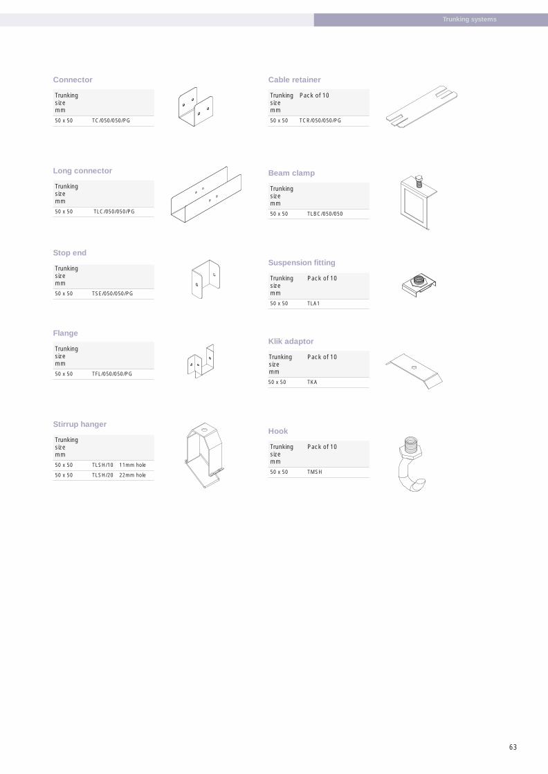
63
Cable retainer
Trunking Pack of 10 sizemm
50 x 50 TCR/050/050/PG
Klik adaptor
Trunking Pack of 10sizemm
50 x 50 TKA
Hook
Trunking Pack of 10sizemm
50 x 50 TMSH
Stirrup hanger
Trunkingsizemm
50 x 50 TLSH/10 11mm hole
50 x 50 TLSH/20 22mm hole
Flange
Trunkingsizemm
50 x 50 TFL/050/050/PG
Beam clamp
Trunkingsizemm
50 x 50 TLBC/050/050
Suspension fitting
Trunking Pack of 10sizemm
50 x 50 TLA1
Long connector
Trunkingsizemm
50 x 50 TLC/050/050/PG
Connector
Trunkingsizemm
50 x 50 TC/050/050/PG
Stop end
Trunkingsize mm
50 x 50 TSE/050/050/PG
Trunking systems
486.5 Metstrut final-04:Layout 1 17/4/09 10:36 Page 63

Metal framing systems
Metal framing systems
64
Four channel profiles are available as plainback or slotted back variants and each can beassembled into multiple configurations whenadditional load carrying capacity is needed.This is further complimented with a wide rangeof brackets and fasteners to achieve almost anyframework assembly and configuration.
Metal framing systems can be found in almostall building sectors and in a wide range ofapplications.
Often used as a first fix component, Metstrutsystems are used to support cable trays, cableladders and other items of capital equipment.
Cut-to-length serviceMetstrut offers a competitive cut-to-lengthservice. By cutting in process the integrity of thepre galvanised coating is maintained on the cutend.
This service reduces the potential for wastewhen cut on site and provides substantiallabour savings.
Pre fabrication serviceConsiderable savings can be made on site byprefabrication modules and bracketry. Metstrutoffers this service see page 86.
The Metstrut metal framing systemprovides flexible and economicalsupport solutions for mechanical andelectrical services.
486.5 Metstrut final-04:Layout 1 17/4/09 10:36 Page 64

65
Metal framing systems
Always use thecomplete
Metstrut system
Metstrut bracket
Metstrut hex. headset screw
Metstrut channel nut
Metstrut channel
486.5 Metstrut final-04:Layout 1 17/4/09 10:36 Page 65

66
StandardsThe Metstrut metal framing system comprises of singleand combination channels, assembly brackets, channelnuts and fasteners. The integration of these items in theiruse, forms the basis of the system and as such should bepurchased as a complete system.
The Metstrut metal framing system conforms to BS 6946:1988, the British Standard Specification for Metalchannel cable support systems for electrical installations.
Independent testing has been carried out to verify theload tables for the various channels and to determine pullout and slip performance of the channel nuts when usedas a system.
It is this system integrity that needs to be maintained forall installations to meet site safety requirements.
The material used for the Metstrut channels meets andsurpasses the minimum yield strength of 250 N/mm2 andbrackets have a minimum yield strength of 170 N/mm2.
Sectional dimensionsThe Standard requires channel sections to meet thedimensional requirements stated when measured not lessthan 150mm from the end. Twist will not be greater than2.5 degrees per metre and bow shall not exceed 5mm forchannel 3m in length and 10mm for channel 6m in length, when measured at the centre of the length.
Metal framing systems
Safe working slip and pull-out loadsThese have been determined by carrying out the tests inaccordance with the method stated in section 8 of thestandard. It should be noted that the channel nuts are avital component within the system and the numerousimported products do not necessarily carry the same loadand should never be mixed with Metstrut systems.
MarkingMetstrut channels are marked at regular intervals alongtheir length in the production process. The standardrequires the name of the manufacturer and BS 6946:1988Brackets and other components are marked by labellingthe packaging.
Combination channelsChannels that are required in multiple configurations e.g.back to back channel, are supplied spot welded asstandard. These channels should always be fullysupported at each end under the bottom face and the loadshould never be hung from just the lips of the bottomchannel. Spot welding should never be loaded in tensionor the load applied as a bending moment.
Load Load
LoadLoad
22.3
41.3
20.6 7.5
+-
+ -
0.7
+- 0.4
+- 0.4
0.5X X
Y
Y
41.3
X X
Y
Y
22.3 +- 0.7
7.5 + -0.5
+- 0.4
41.3 +- 0.4
486.5 Metstrut final-04:Layout 1 17/4/09 10:36 Page 66

5. Alternative beam safe load tables are provided for auniformly distributed load or load concentrated near thecentre of the span.eg:
6. Beam loads and corresponding deflections arecalculated at a stress of 175N/mm2 i.e.: using a globalfactor of safety of 1.6 to determine safe working loads fromlimit state analysis (ultimate stress ÷ 1.6 = 175N/mm2).
Beam safe loads tabulated with corresponding deflectionsmay be used in the rare case where excessive deflectiondoes not impair the strength or efficiency of the structureor its components or cause damage to the supported work.
Alternative safe loads are tabulated with deflectionslimited to span/200 or span/360 at the discretion of thedesigner and recommended where deflections are critical.
It is easily recognisable from the tables whether thedesign of the beam is governed by deflection or stress on agiven span i.e.: the critical load is highlighted in colour.
7. Column effective lengths shall be determined by thedesigner in accordance with Table 9 of BS 5950: Part 5:1998.
8. Beam loads are generally applied at the column face viathe connection bracket. Therefore column safe load tablesare provided allowing for this eccentricity of load from thecentroid of the section.
Alternative combinations
For safe loads on alternative combinations not tabulatedplease refer to Metsec Technical Department.
Stainless steelThe mechanical properties of stainless steel aresignificantly different from those for carbon steel and safeload tables must not be used for sections in this material.Please consult Metsec Technical Department for advice.
Material specification1. Channels: manufactured from steel complying with BS EN 10326:2004 pre galvanised, BS EN 10025-2:2004mild steel hot dip galvanised after manufacture to BS EN 1461:1999 and BS EN 10088-2:2005 stainless steelgrade 316L.
2. Brackets: manufactured from steel complying with BS EN 10025-2:2004 mild steel hot dip galvanised aftermanufacture to BS EN 1461:1999 and BS EN 10088-2:2005stainless steel grade 316L.
3. Fixings: bolts, hexagon nuts, screws and washersmanufactured from steel complying with DIN938/8, DIN933/8.8, BS4320 and zinc plated and CR3 passivated orhot dip galvanised after manufacture to BS EN 1461:1999.Stainless steel to BS EN 10088-2:2005 grade 316L A4.
Dimensions and tolerancesIn accordance with BS 6946:1988 Metal Channel CableSupport Systems for Electrical Installations.
Channel notationMetsec channel references are serialised for easyrecognition and use, eg: channel series MS4125 comprisessingle channel or combinations of channel within the basicsection profile thus:
MS 41 25 (C2)
OR MS 41 15
Load tablesComprehensive load tables are provided for each channelseries:MS4125 series - page 68MS2125 series - pages 69MS4115 series - pages 70MS2115 series - pages 71Slotted sections - pages 72-3
Basis of design and formulation of load tables
1. Safe loads calculated in accordance with BS 5950:Part 5:1998 Code of Practice for Design of ColdFormed Sections.
2. Minimum Yield Stress (Ys) 280N/mm2 (Z 28 material).
3. Beams assumed simply supported and provided withadequate lateral restraint over the given span.
4. Beam loads are applied through the shear centre of thesection in the direction indicated in the tables.
67
Metsecstandard
prefix
Channelflange B
Signifiesmaterial
thicknesse.g. 2.5or 1.5
Suffixcombinationsusing 2-no.standard
sections in thisexample
Le
Beam span
Load uniformly distributed
Le
Beam span
Load concentrated near centre of span
B=21
D=41D=41
B=41
t=2.5mmt=1.5mm
(C2)
centroid
eccentricity
load
Metal framing systems
486.5 Metstrut final-04:Layout 1 17/4/09 10:36 Page 67

Metal framing systems
68
Metal framing systems
MS4125
7.5
22.2= =
= =
41.3
41.3
Beam load application
18.2
23.1
Eccentriccolumn loadapplication
X X
Y
Y
41.3
41.3
41.3
82.6
= =Eccentriccolumn loadapplication
Beam load application
X X
Y
Y
Area Wt Ixx Zxx Zxx rxx Iyy Zyy ryy
cm2 kg/m cm4 (top) (btm) cm cm4 cm3 cm
cm3 cm3
3.39 2.67 7.32 3.17 4.03 1.47 9.34 4.52 1.66
Safe load tables
Le (m)
Safe workingloads in kg
uniform
Def.limit
span/200(kg)
Def.limit
span/360(kg)
Safe workingloads in kg
concentrated
Def. limit
span/200(kg)
Def. limit
span/360(kg)
Safecolumnloadskg at
centroid
Safecolumnloadskg atface
(kg) (mm)Load Def.
Section properties
Area Wt Ixx Zxx Zxx rxx Iyy Zyy ryy
cm2 kg/m cm4 (top) (btm) cm cm4 cm3 cm
cm3 cm3
6.78 5.34 37.20 9.01 9.01 2.34 18.68 9.05 1.66
∝Le/ryy >180
0.6 754 1.39 754 754 377 1.11 377 377 5176 1557
0.7 646 1.88 646 646 324 1.51 324 324 4818 1496
0.8 566 2.46 566 510 283 1.98 283 283 4371 1424
0.9 503 3.11 503 403 252 2.50 252 252 3928 1351
1.0 452 3.85 452 327 226 3.08 226 204 3512 1280
1.1 411 4.66 411 270 206 3.72 206 169 3146 1211
1.2 377 5.54 377 227 189 4.43 189 142 2801 1142
1.3 348 6.51 348 193 175 5.21 175 121 2541 1084
1.4 324 7.54 300 167 162 6.04 162 104 2323 1033
1.5 301 8.66 261 145 151 6.92 151 91 2112 980
1.6 282 9.86 230 128 141 7.88 141 80 1961 939
1.7 267 11.12 203 113 133 8.91 127 71 1807 895
1.8 251 12.47 181 101 125 9.98 113 63 1675 855
1.9 239 13.89 163 91 120 11.11 102 57 1586 827
2.0 226 15.39 147 82 113 12.31 92 51 1486 795
2.1 215 16.97 133 74 108 13.58 83 46 1378 758
2.2 206 18.63 121 68 103 14.90 76 42 1304 731
2.3 197 20.36 111 62 99 16.28 69 39 1239 707
2.4 188 22.16 102 57 94 17.73 64 35
2.5 181 24.06 94 52 91 19.25 59 33
2.6 174 26.02 87 49 87 20.81 54 30
2.7 168 28.06 81 45 84 22.45 50 28
2.8 161 30.17 75 42 81 24.14 47 26
2.9 156 32.37 70 39 78 25.89 44 24
3.0 151 34.63 65 37 76 27.71 41 23
0.6 2143 0.77 2143 2143 1072 0.61 1072 1072 11636 2886
0.7 1837 1.05 1837 1837 918 0.84 918 918 11431 2863
0.8 1607 1.38 1607 1607 804 1.10 804 804 11193 2836
0.9 1429 1.75 1429 1429 714 1.40 714 714 10912 2805
1.0 1286 2.15 1286 1286 643 1.72 643 643 10574 2769
1.1 1169 2.61 1169 1169 584 2.09 584 584 10168 2726
1.2 1072 3.10 1072 1072 536 2.48 536 536 9685 2675
1.3 989 3.64 989 981 495 2.92 495 495 9129 2616
1.4 918 4.22 918 846 459 3.38 459 459 8518 2549
1.5 857 4.85 857 737 429 3.88 429 429 7882 2476
1.6 804 5.51 804 648 402 4.40 402 402 7253 2397
1.7 756 6.23 756 574 378 4.98 378 359 6653 2316
1.8 714 6.98 714 512 357 5.58 357 320 6096 2233
1.9 677 7.77 677 459 338 6.22 338 287 5588 2151
2.0 643 8.61 643 415 321 6.89 321 259 5129 2070
2.1 612 9.50 612 376 306 7.60 306 235 4717 1991
2.2 584 10.43 584 343 292 8.35 292 214 4347 1915
2.3 559 11.39 559 314 280 9.11 280 196 4016 1840
2.4 536 12.40 518 288 268 9.92 268 180 3718 1769
2.5 514 13.46 478 265 257 10.76 257 166 3451 1701
2.6 495 14.56 442 245 247 11.65 247 153 3210 1635
2.7 476 15.70 410 228 238 12.56 238 142 2993 1572
2.8 459 16.88 381 212 230 13.50 230 132 2797 1512
2.9 443 18.11 355 197 222 14.49 222 123 2619 1454
3.0 429 19.38 332 184 214 15.50 207 115
∝Le >180
rxx
MS4125-C2(Combination comprising 2 no. MS4125)
(kg) (kg)Load Def.
486.5 Metstrut final-04:Layout 1 17/4/09 10:36 Page 68

69
Metal framing systems
12.1
8.5
==
= =
22.2
41.3
20.6 7.5
Eccentriccolumn loadapplication
X X
Beam load application
Y
Y
= =
41.3
20.6
20.641.2
Eccentriccolumn loadapplication
Y
X X
Beam load application
Y
Area Wt Ixx Zxx Zxx rxx Iyy Zyy ryy
cm2 kg/m cm4 (top) (btm) cm cm4 cm3 cm
cm3 cm3
2.35 1.85 1.21 1.00 1.43 0.72 5.44 2.63 1.52
Safe load tables
Le (m)
Safe workingloads in kg
uniform
Def. limit
span/200(kg)
Def. limit
span/360(kg)
Safe workingloads in kg
concentrated
Def. limit
span/200(kg)
Def. limit
span/360(kg)
Safecolumnloadskg at
centroid
Safecolumnloadskg atface
Section properties
Area Wt Ixx Zxx Zxx rxx Iyy Zyy ryy
cm2 kg/m cm4 (top) (btm) cm cm4 cm3 cm
cm3 cm3
4.71 3.70 5.78 2.81 2.81 1.11 10.88 5.27 1.52
0.6 237 2.64 237 150 118 2.11 118 93 2978 894
0.7 203 3.59 198 110 101 2.87 101 69 2471 821
0.8 177 4.68 151 84 89 3.75 89 53 2019 747
0.9 158 5.94 120 66 79 4.75 75 42 1657 677
1.0 142 7.33 97 54 71 5.86 61 34 1375 613
1.1 129 8.87 80 44 65 7.09 50 28 1156 556
1.2 118 10.55 67 37 59 8.44 42 23 984 505
1.3 109 12.38 57 32 55 9.91 36 20
1.4 101 14.36 49 27 51 11.49 31 17
1.5 95 16.49 43 24 47 13.18 27 15
1.6 89 18.76 38 21 44 15.00 24 13
1.7 84 21.18 34 19 42 16.95 21 12
1.8 79 23.74 30 17 39 19.00 19 10
1.9 75 26.45 27 15 37 21.16 17 9
2.0 71 29.31 24 13 35 23.45 15 8
2.1 68 32.31 22 12 34 25.86 14 8
2.2 65 35.46 20 11 32 28.38 13 7
2.3 62 38.76 18 10 31 31.01 11 6
2.4 59 42.20 17 9 30 33.77 11 6
2.5 57 45.80 16 9 28 36.63 10 5
2.6 55 49.53 14 8 27 39.63 9 5
2.7 53 53.42 13 7 26 42.74 8 5
2.8 51 57.45 12 7 25 45.95 8 4
2.9 49 61.62 12 6 24 49.29 7 4
3.0 47 65.95 11 6 24 52.76 7 4
0.6 667 1.55 667 667 334 1.24 334 334 7582 1765
0.7 572 2.11 572 526 286 1.69 286 286 7214 1720
0.8 501 2.76 501 403 250 2.21 250 250 6733 1665
0.9 445 3.50 445 318 222 2.80 222 199 6140 1601
1.0 400 4.32 400 258 200 3.46 200 161 5484 1528
1.1 364 5.22 364 213 182 4.17 182 133 4835 1451
1.2 334 6.22 322 179 167 4.97 167 112 4243 1372
1.3 308 7.29 274 152 154 5.84 154 95 3726 1295
1.4 286 8.46 237 131 143 6.77 143 82 3284 1221
1.5 267 9.71 206 115 133 7.77 129 72 2908 1150
1.6 250 11.05 181 101 125 8.84 113 63 2589 1084
1.7 236 12.47 161 89 118 9.98 100 56 2317 1022
1.8 222 13.98 143 80 111 11.19 89 50 2084 964
1.9 211 15.58 129 71 105 12.47 80 45 1884 910
2.0 200 17.26 116 64 100 13.81 72 40
2.1 191 19.03 105 58 95 15.23 66 37
2.2 182 20.89 96 53 91 16.72 60 33
2.3 174 22.83 88 49 87 18.27 55 30
2.4 167 24.86 81 45 83 19.89 50 28
2.5 160 26.98 74 41 80 21.58 46 26
2.6 154 29.18 69 38 77 23.35 43 24
2.7 148 31.46 64 35 74 25.18 40 22
2.8 143 33.84 59 33 72 27.07 37 21
2.9 138 36.30 55 31 69 29.04 34 19
3.0 133 38.84 52 29 67 31.08 32 18
∝Le >180
rxx
∝Le >180
ryy
MS2125
MS2125-C2(Combination comprising two MS2125)
(kg) (mm)Load Def.
(kg) (kg)Load Def.
486.5 Metstrut final-04:Layout 1 17/4/09 10:36 Page 69

Metal framing systems
70
Metal framing systems
7.5
41.3
41.3
22.7
Y
XX
18.6
22.2 ==
= =
Eccentriccolumn loadapplication
Beam load application
Y
= =
82.6 41.3
41.3
41.3
X X
Y
Eccentriccolumn loadapplication
Beam load application
Y
Area Wt Ixx Zxx Zxx rxx Iyy Zyy ryy
cm2 kg/m cm4 (top) (btm) cm cm4 cm3 cm
cm3 cm3
2.14 1.69 4.99 2.20 2.68 1.53 6.14 2.97 1.69
Safe load tables
Le (m)
Safe workingloads in kg
uniform
Def.limit
span/200(kg)
Def. limit
span/360(kg)
Safe workingloads in kg
concentrated
Def. limit
span/200(kg)
Def. limit
span/360(kg)
Safecolumnloadskg at
centroid
Safecolumnloadskg atface
Section properties
Area Wt Ixx Zxx Zxx rxx Iyy Zyy ryy
cm2 kg/m cm4 (top) (btm) cm cm4 cm3 cm
cm3 cm3
4.29 3.38 24.82 6.01 6.01 2.41 12.27 5.94 1.69
∝Le >180
rxx
0.6 523 1.41 523 523 261 1.13 261 261 3297 1061
0.7 448 1.92 448 448 224 1.54 224 224 3057 1015
0.8 392 2.51 392 348 196 2.01 196 196 2743 957
0.9 349 3.17 349 275 174 2.53 174 172 2418 897
1.0 314 3.92 314 222 157 3.14 157 139 2109 836
1.1 285 4.74 285 184 143 3.79 143 115 1857 782
1.2 261 5.64 261 154 131 4.52 131 97 1625 727
1.3 241 6.62 237 132 121 5.30 121 82 1432 677
1.4 224 7.68 204 114 112 6.14 112 71 1270 631
1.5 209 8.81 178 99 105 7.05 105 62 1148 594
1.6 196 10.03 156 87 98 8.03 98 54 1033 556
1.7 185 11.32 139 77 92 9.05 87 48 934 522
1.8 174 12.69 124 69 87 10.15 77 43 862 495
1.9 165 14.14 111 62 83 11.32 69 39 788 466
2.0 157 15.67 100 56 78 12.53 63 35
2.1 149 17.27 91 50 75 13.82 57 32
2.2 143 18.96 83 46 71 15.17 52 29
2.3 136 20.72 76 42 68 16.58 47 26
2.4 131 22.56 70 39 65 18.05 43 24
2.5 125 24.48 64 36 63 19.58 40 22
2.6 121 26.48 59 33 60 21.18 37 21
2.7 116 28.55 55 31 58 22.85 34 19
2.8 112 30.71 51 28 56 24.56 32 18
2.9 108 32.94 48 26 54 26.36 30 17
3.0 105 35.25 44 25 52 28.20 28 15
0.6 1429 0.78 1429 1429 715 0.61 715 715 7370 1901
0.7 1225 1.06 1225 1225 613 0.84 613 613 7245 1886
0.8 1072 1.38 1072 1072 536 1.10 536 536 7100 1868
0.9 953 1.74 953 953 476 1.40 476 476 6931 1848
1.0 858 2.15 858 858 429 1.73 429 429 6729 1825
1.1 780 2.61 780 780 390 2.09 390 390 6486 1797
1.2 715 3.10 715 715 357 2.48 357 357 6197 1765
1.3 660 3.64 660 655 330 2.91 330 330 5862 1727
1.4 613 4.22 613 565 306 3.38 306 306 5490 1684
1.5 572 4.84 572 492 286 3.88 286 286 5099 1636
1.6 536 5.51 536 432 268 4.40 268 268 4705 1585
1.7 505 6.22 505 383 252 4.98 252 239 4326 1532
1.8 476 6.98 476 342 238 5.58 238 213 3971 1478
1.9 451 7.77 451 307 226 6.22 226 192 3646 1423
2.0 429 8.61 429 277 214 6.89 214 173 3350 1370
2.1 408 9.50 408 251 204 7.59 204 157 3083 1318
2.2 390 10.42 390 229 195 8.33 195 143 2843 1267
2.3 373 11.39 373 209 186 9.11 186 131 2628 1218
2.4 357 12.40 346 192 179 9.92 179 120 2434 1170
2.5 343 13.46 319 177 172 10.76 172 111 2260 1125
2.6 330 14.55 295 164 165 11.65 165 102 2103 1081
2.7 318 15.70 273 152 159 12.56 159 95 1961 1040
2.8 306 16.88 254 141 153 13.50 153 88 1833 1000
2.9 296 18.11 237 132 148 14.49 148 82 1717 962
3.0 286 19.38 221 123 143 15.50 138 77 1611 925
MS4115
MS4115-C2(Combination comprising 2 no. MS4115)
(kg) (mm)Load Def.
(kg) (kg)Load Def.
486.5 Metstrut final-04:Layout 1 17/4/09 10:36 Page 70

71
Metal framing systems
22.2Eccentriccolumn loadapplication
Y
XX
7.5 20.6
41.3
=
= =
12.1
8.5
=
Beam load application
Y
20.6
20.6
41.3
41.2
==Y
X X
Eccentriccolumn loadapplication
Beam load application
Y
Area Wt Ixx Zxx Zxx rxx Iyy Zyy ryy
cm2 kg/m cm4 (top) (btm) cm cm4 cm3 cm
cm3 cm3
1.52 1.20 0.89 0.75 1.03 0.77 3.68 1.78 1.55
Safe load tables
Le (m)
Safe workingloads in kg
uniform
Def. limit
span/200(kg)
Def. limit
span/360(kg)
Safe workingloads in kg
concentrated
Def. limit
span/200(kg)
Def. limit
span/360(kg)
Safecolumnloadskg at
centroid
Safecolumnloadskg atface
Section properties
Area Wt Ixx Zxx Zxx rxx Iyy Zyy ryy
cm2 kg/m cm4 (top) (btm) cm cm4 cm3 cm
cm3 cm3
3.03 2.40 4.08 1.98 1.98 1.16 7.35 3.56 1.56
∝Le >180
rxx
∝Le >180
ryy
MS2115
MS2115-C2(Combination comprising 2 no. MS2115)
0.6 179 2.69 179 111 89 2.15 89 69 2051 663
0.7 153 3.66 147 81 77 2.93 77 51 1748 612
0.8 134 4.78 112 62 67 3.83 67 39 1453 558
0.9 119 6.05 89 49 60 4.84 55 31 1203 506
1.0 107 7.46 72 40 54 5.98 45 25 1004 459
1.1 97 9.03 59 33 49 7.23 37 21 847 416
1.2 89 10.75 50 28 45 8.60 31 17 722 378
1.3 82 12.62 42 24 41 10.09 27 15 622 344
1.4 77 14.63 37 20 38 11.70 23 13
1.5 71 16.80 32 18 36 13.44 20 11
1.6 67 19.11 28 16 33 15.28 18 10
1.7 63 21.57 25 14 32 17.25 16 9
1.8 60 24.19 22 12 30 19.35 14 8
1.9 56 26.95 20 11 28 21.56 12 7
2.0 54 29.86 18 10 27 23.88 11 6
2.1 51 32.92 16 9 26 26.34 10 6
2.2 49 36.13 15 8 24 28.90 9 5
2.3 47 39.49 14 8 23 31.59 8 5
2.4 45 43.00 12 7 22 34.39 8 4
2.5 43 46.66 11 6 21 37.32 7 4
2.6 41 50.46 11 6 21 40.37 7 4
2.7 40 54.42 10 5 20 43.53 6 3
2.8 38 58.52 9 5 19 46.82 6 3
2.9 37 62.78 9 5 18 50.23 5 3
3.0 36 67.18 8 4 18 53.76 5 3
0.6 472 1.55 472 472 236 1.24 236 236 4938 1224
0.7 404 2.12 404 372 202 1.69 202 202 4729 1194
0.8 354 2.76 354 284 177 2.21 177 177 4458 1159
0.9 314 3.50 314 225 157 2.80 157 140 4117 1117
1.0 283 4.32 283 182 141 3.46 141 114 3725 1069
1.1 257 5.22 257 150 129 4.19 129 94 3319 1017
1.2 236 6.22 228 126 118 4.98 118 79 2934 963
1.3 218 7.30 194 108 109 5.84 109 67 2589 910
1.4 202 8.46 167 93 101 6.77 101 58 2290 859
1.5 189 9.71 146 81 94 7.77 91 51 2033 810
1.6 177 11.05 128 71 88 8.84 80 44 1813 763
1.7 166 12.48 113 63 83 9.98 71 39 1624 720
1.8 157 13.99 101 56 79 11.19 63 35 1463 679
1.9 149 15.59 91 50 74 12.47 57 32 1323 641
2.0 141 17.27 82 46 71 13.81 51 28 1202 606
2.1 135 19.04 74 41 67 15.23 46 26
2.2 129 20.90 68 38 64 16.72 42 24
2.3 123 22.84 62 34 62 18.27 39 22
2.4 118 24.87 57 32 59 19.89 36 20
2.5 113 26.98 52 29 57 21.59 33 18
2.6 109 29.19 48 27 54 23.35 30 17
2.7 105 31.47 45 25 52 25.18 28 16
2.8 101 33.85 42 23 51 27.08 26 15
2.9 98 36.31 39 22 49 29.04 24 14
3.0 94 38.86 36 20 47 31.09 23 13
(kg) (mm)Load Def.
(kg) (kg)Load Def.
486.5 Metstrut final-04:Layout 1 17/4/09 10:36 Page 71

Metal framing systems
72
Metal framing systems
MS4125 - slotted
7.5
22.2=
= =
=
41.3
41.3
20.2
14 x 28slots at 50 crs
21.1
Eccentriccolumn loadapplication
XX
Y
Beam load application
Y
=
= =
=
20.8
22.2
20.5
Y
X X
7.5
Eccentriccolumn loadapplication
41.3
41.3
Beam load application
Y
14 x 28slots at 50 crs
Area Wt Ixx Zxx Zxx rxx Iyy Zyy ryy
cm2 kg/m cm4 (top) (btm) cm cm4 cm3 cm
cm3 cm3
3.04 2.53 6.20 2.94 3.07 1.43 9.28 4.50 1.75
Safe load tables
Le (m)
Safe workingloads in kg
uniform
Def. limit
span/200(kg)
Def. limit
span/360(kg)
Safe workingloads in kg
concentrated
Def. limit
span/200(kg)
Def. limit
span/360(kg)
Safecolumnloadskg at
centroid
Safecolumnloadskg atface
Section properties
Area Wt Ixx Zxx Zxx rxx Iyy Zyy ryy
cm2 kg/m cm4 (top) (btm) cm cm4 cm3 cm
cm3 cm3
1.93 1.61 4.25 2.01 2.10 1.48 6.10 2.96 1.78
0.6 698 1.52 698 698 349 1.22 349 349 4541 1491
0.7 599 2.06 599 564 299 1.65 299 299 4151 1416
0.8 524 2.70 524 432 262 2.16 262 262 3701 1333
0.9 466 3.41 466 341 233 2.73 233 213 3250 1247
1.0 419 4.21 419 276 210 3.37 210 173 2842 1163
1.1 381 5.10 381 228 190 4.08 190 143 2521 1090
1.2 349 6.07 345 192 175 4.85 175 120 2229 1019
1.3 322 7.12 294 163 161 5.70 161 102 2011 960
1.4 299 8.26 254 141 150 6.60 150 88 1808 902
1.5 279 9.48 221 123 140 7.59 138 77 1637 849
1.6 262 10.78 194 108 131 8.63 121 67 1494 802
1.7 246 12.18 172 96 123 9.74 108 60 1391 767
1.8 233 13.65 153 85 116 10.92 96 53 1286 729
1.9 221 15.21 138 77 110 12.17 86 48 1196 695
2.0 210 16.86 124 69 105 13.48 78 43 1118 664
2.1 200 18.58 113 63 100 14.86 70 39
2.2 190 20.39 103 57 95 16.32 64 36
2.3 182 22.29 94 52 91 17.83 59 33
2.4 175 24.27 86 48 87 19.42 54 30
2.5 168 26.34 80 44 84 21.07 50 28
2.6 161 28.49 74 41 81 22.78 46 26
2.7 155 30.72 68 38 78 24.58 43 24
2.8 150 33.04 63 35 75 26.43 40 22
2.9 144 35.44 59 33 72 28.35 37 21
3.0 140 37.92 55 31 70 30.37 35 19
0.6 479 1.52 479 479 239 1.22 239 239 2930 1012
0.7 410 2.07 410 386 205 1.65 205 205 2691 961
0.8 359 2.70 359 296 180 2.16 180 180 2385 899
0.9 319 3.41 319 234 160 2.73 160 146 2082 836
1.0 287 4.21 287 189 144 3.37 144 118 1803 773
1.1 261 5.10 261 156 131 4.08 131 98 1564 714
1.2 239 6.07 237 131 120 4.81 120 82 1364 660
1.3 221 7.12 202 112 110 5.70 110 70 1199 611
1.4 205 8.26 174 97 103 6.60 103 60 1061 567
1.5 192 9.48 151 84 96 7.59 95 53 947 527
1.6 180 10.79 133 74 90 8.63 83 46 850 491
1.7 169 12.18 118 66 84 9.74 74 41 778 463
1.8 160 13.66 105 58 80 10.92 66 37 708 434
1.9 151 15.21 94 52 76 12.17 59 33
2.0 144 16.86 85 47 72 13.49 53 30
2.1 137 18.59 77 43 68 14.87 48 27
2.2 131 20.40 70 39 65 16.32 44 24
2.3 125 22.30 64 36 62 17.83 40 22
2.4 120 24.28 59 33 60 19.42 37 21
2.5 115 26.34 55 30 57 21.07 34 19
2.6 110 28.49 50 28 55 22.80 32 18
2.7 106 30.72 47 26 53 24.58 29 16
2.8 103 33.04 43 24 51 26.43 27 15
2.9 99 35.44 41 23 50 28.35 25 14
3.0 96 37.93 38 21 48 30.35 24 13
∝Le >180
rxx
∝Le >180
ryy
MS4115 - slotted
(kg) (mm)Load Def.
(kg) (kg)Load Def.
486.5 Metstrut final-04:Layout 1 17/4/09 10:36 Page 72

73
Metal framing systems
X
Y
X10.9
9.7
Eccentriccolumn loadapplication22.2= =
7.520.6
= =
41.3
Beam load application
Y
14 x 28slots at 50 crs
Eccentriccolumn loadapplication
XX10.6
10.0
22.2= =
Y
7.520.6
= =
41.3
Beam load application
Y
14 x 28slots at 50 crs
Area Wt Ixx Zxx Zxx rxx Iyy Zyy ryy
cm2 kg/m cm4 (top) (btm) cm cm4 cm3 cm
cm3 cm3
2.00 1.71 0.99 0.91 1.02 0.70 5.28 2.56 1.62
Safe load tables
Le (m)
Safe workingloads in kg
uniform
Def. limit
span/200(kg)
Def. limit
span/360(kg)
Safe workingloads in kg
concentrated
Def. limit
span/200(kg)
Def. limit
span/360(kg)
Safecolumnloadskg at
centroid
Safecolumnloadskg atface
Section properties
Area Wt Ixx Zxx Zxx rxx Iyy Zyy ryy
cm2 kg/m cm4 (top) (btm) cm cm4 cm3 cm
cm3 cm3
1.31 1.12 0.74 0.70 0.75 0.75 3.64 1.76 1.67
0.6 216 2.94 216 123 108 2.36 108 77 2490 841
0.7 186 4.00 162 90 93 3.20 93 56 2052 764
0.8 162 5.22 124 69 81 4.17 78 43 1671 688
0.9 144 6.61 98 55 72 5.29 61 34 1368 617
1.0 130 8.16 80 44 65 6.53 50 28 1134 555
1.1 118 9.87 66 37 59 7.90 41 23 953 499
1.2 108 11.74 55 31 54 9.40 35 19 810 451
1.3 100 13.78 47 26 50 11.02 29 16
1.4 93 15.98 41 23 46 12.79 25 14
1.5 87 18.35 35 20 43 14.68 22 12
1.6 81 20.88 31 17 41 16.70 19 11
1.7 76 23.57 28 15 38 18.85 17 10
1.8 72 26.42 25 14 36 21.15 15 9
1.9 68 29.44 22 12 34 23.55 14 8
2.0 65 32.62 20 11 32 26.10 12 7
2.1 62 35.97 18 10 31 28.77 11 6
2.2 59 39.47 16 9 30 31.58 10 6
2.3 56 43.14 15 8 28 34.51 9 5
2.4 54 46.98 14 8 27 37.58 9 5
2.5 52 50.97 13 7 26 40.78 8 4
2.6 50 55.13 12 7 25 44.11 7 4
2.7 48 59.45 11 6 24 47.56 7 4
2.8 46 63.94 10 6 23 51.15 6 4
2.9 45 68.59 9 5 22 54.87 6 3
3.0 43 73.40 9 5 22 58.73 6 3
0.6 166 3.01 165 92 83 2.41 83 57 1738 632
0.7 142 4.09 121 67 71 3.28 71 42 1469 577
0.8 124 5.35 93 52 62 4.28 58 32 1215 521
0.9 110 6.77 73 41 55 5.41 46 25 1003 468
1.0 99 8.35 59 33 50 6.68 37 21 836 420
1.1 90 10.11 49 27 45 8.09 31 17 704 378
1.2 83 12.03 41 23 41 9.63 26 14 600 341
1.3 76 14.12 35 20 38 11.29 22 12 516 309
1.4 71 16.37 30 17 35 13.09 19 11
1.5 66 18.79 26 15 33 15.04 17 9
1.6 62 21.38 23 13 31 17.10 15 8
1.7 58 24.14 21 11 29 19.32 13 7
1.8 55 27.06 18 10 28 21.64 11 6
1.9 52 30.15 16 9 26 24.12 10 6
2.0 50 33.41 15 8 25 26.73 9 5
2.1 47 36.83 13 7 24 29.47 8 5
2.2 45 40.42 12 7 23 32.35 8 4
2.3 43 44.18 11 6 22 35.34 7 4
2.4 41 48.11 10 6 21 38.49 6 4
2.5 40 52.20 10 5 20 41.77 6 3
2.6 38 56.46 9 5 19 45.17 5 3
2.7 37 60.89 8 5 18 48.70 5 3
2.8 35 65.48 8 4 18 52.39 5 3
2.9 34 70.24 7 4 17 56.19 4 2
3.0 33 75.17 7 4 17 60.13 4 2
∝Le >180
ryy
∝Le >180
rxx
MS2125 - slotted
MS2115 - slotted
(kg) (mm)Load Def.
(kg) (kg)Load Def.
486.5 Metstrut final-04:Layout 1 17/4/09 10:36 Page 73

Metal framing systems
74
Cantilever arm details
L (Standard Length)
L (Standard Length)
Cantilever arms - single
Finish: Post hot dip galvanised as standard, stainless steel grade 316, suffix SS
Ref L (mm) Wt (kg)
MS150A 150 0.77
MS300A 300 1.16
MS450A 450 1.56
MS600A 600 1.95
MS750A 750 2.35
Cantilever arms - double
Finish: Post hot dip galvanised as standard, stainless steel grade 316, suffix SS
Ref L (mm) Wt (kg)
MS150E 150 1.26
MS300E 300 2.05
MS450E 450 2.85
MS600E 600 3.64
MS750E 750 4.43
Recommended safe loads (kg.) for arm boltedto 2.5mm thick channel (M12 bolt torque 65Nm)
Total uniformly Concentrated X (m) distributed load load
0.10 684 542
0.15 608 377
0.20 542 283
0.25 452 226
0.30 377 188
0.35 323 162
0.40 283 141
0.45 251 126
0.50 226 113
0.55 206 103
0.60 188 94
0.65 174 87
0.70 162 81
0.75 151 75
NB: Arms have been independently tested (M12 bolt torque 65 Nm). Tabulatedsafe loads satisfy minimum factor of safety of 3 on continuous slip and limiteddesign stresses in channel arms and their fixings.
Recommended safe loads (kg.) for arm boltedto 2.5mm thick channel (M12 bolt torque 65Nm)
Total uniformly Concentrated X (m) distributed load load
0.10 684 643
0.15 684 552
0.20 643 484
0.25 594 430
0.30 552 388
0.35 516 353
0.40 484 324
0.45 455 299
0.50 430 277
0.55 408 259
0.60 387 243
0.65 369 229
0.70 353 216
0.75 337 205
NB: Arms have been independently tested (M12 bolt torque 65 Nm). Tabulatedsafe loads satisfy minimum factor of safety of 3 on continuous slip and limiteddesign stresses in channel arms and their fixings.
Metal framing systems
Le
x
Le
x
Le
x
Le
x
486.5 Metstrut final-04:Layout 1 17/4/09 10:36 Page 74

75
Channel - plain
Finish: pre galvanised = PG, post galvanised = HDG, stainless steel grade 316 = SS
Lengthm
3 MS4125PG3
6 MS4125PG6
3 MS4125PG3C2
6 MS4125PG6C2
3 MS2125PG3
6 MS2125PG6
3 MS2125PG3C2
6 MS2125PG6C2
3 MS4115PG3
6 MS4115PG6
3 MS4115PG3C2
6 MS4115PG6C2
3 MS2115PG3
6 MS2115PG6
3 MS2115PG3C2
6 MS2115PG6C2
Channel - slotted
Finish: pre galvanised = PG, post galvanised = HDG, stainless steel grade 316 = SS
Lengthm
3 MS4125PG3S11
6 MS4125PG6S11
3 MS4125PG3S14
6 MS4125PG6S14
3 MS2125PG3S11
6 MS2125PG6S11
3 MS2125PG3S14
6 MS2125PG6S14
3 MS4115PG3S11
6 MS4115PG6S11
3 MS4115PG3S14
6 MS4115PG6S14
3 MS2115PG3S11
6 MS2115PG6S11
3 MS2115PG3S14
6 MS2115PG6S14
Channel nuts
Finish: BZP as standard, post hot dip galvanised suffix HDG, stainless steel grade 316, suffix SS
Plain channel nuts
MPN06
MPN08
MPN10
MPN12
Short spring channel nuts
MSN06
MSN08
MSN10
MSN12
Long spring channel nuts
MLN06
MLN08
MLN10
MLN12
PVC end caps
Black = B, White = W
41mm deep channel
PVC41B
PVC41W
21mm deep channel
PVC21B
PVC21W
Closure strip - 3m long
PVC white = W, PVC black = B, pre galvanisedsteel = S
MS41CLW3
MS41CLB3
MS41CLS3
Slot sizes in channel
S11 = 11 x 22mm
S14 = 14 x 28mm
50mmcentres
Metal framing systems
Nut type
486.5 Metstrut final-04:Layout 1 17/4/09 10:36 Page 75

Brackets
Finish: Post hot dip galvanised as standard, stainless steel grade 316, suffix SS
MSF501/06 MSF502 MSF503
MSF501/08
MSF501/10
MSF501/12
MSF504 MSF505 MSF506
MSF507 MSA600 MSA601
MSA602 MSA603 MSA604
MSA605 MSA606 MSA607
MSA608 MSA609 MSA610
MSA611 MSA612 MSA614
MSA615 MSA616 MSA617
MSZ700 MSZ701 MSZ702
Metal framing systems
76
Metal framing systems
45°
SpecifySpecify 45°
486.5 Metstrut final-04:Layout 1 17/4/09 10:36 Page 76
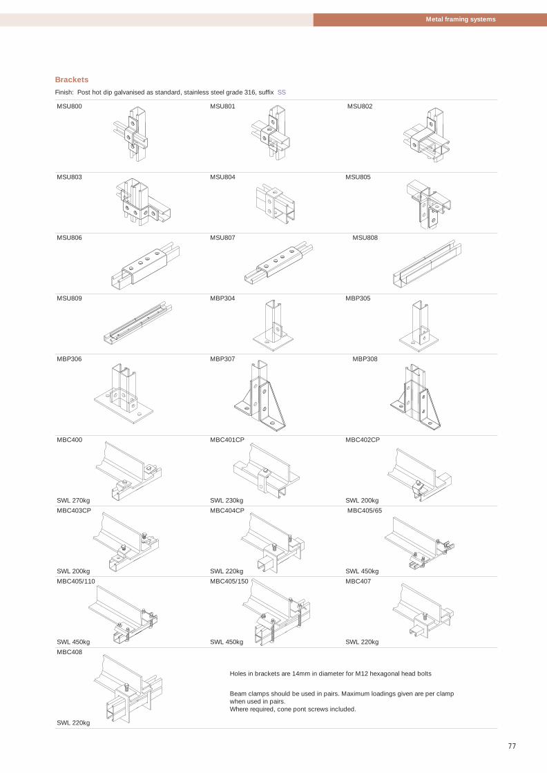
77
Metal framing systems
Holes in brackets are 14mm in diameter for M12 hexagonal head bolts
Beam clamps should be used in pairs. Maximum loadings given are per clampwhen used in pairs.Where required, cone pont screws included.
Brackets
Finish: Post hot dip galvanised as standard, stainless steel grade 316, suffix SS
MSU800 MSU801 MSU802
MSU803 MSU804 MSU805
MSU806 MSU807 MSU808
MSU809 MBP304 MBP305
MBP306 MBP307 MBP308
MBC400 MBC401CP MBC402CP
SWL 270kg SWL 230kg SWL 200kg
MBC403CP MBC404CP MBC405/65
SWL 200kg SWL 220kg SWL 450kg
MBC405/110 MBC405/150 MBC407
SWL 450kg SWL 450kg SWL 220kg
MBC408
SWL 220kg
486.5 Metstrut final-04:Layout 1 17/4/09 10:36 Page 77

Metstrut has developed a new rapid installationsystem that comprises of a unique 2mm thickribbed channel and a range of pre assembledbrackets.
The channel profile is available as standard inpre galvanised material, with post hot dipgalvanised to order, in 2m, 4m and 6m lengths.Alternative lengths are available to order andMetstrut also offers a cut-to-length service. TheMulti slot back allows for a flexible range offixings from M6 to M12, at 100mm centres, toeither the supporting structure or bracketry.
All components are fully compatible with otherMetstrut Channels and brackets for a fullyintegrated system.
The unique and patented “Rapid InstallationSystem” has pre assembled channel nutsincorporated into the bracket complete withM10 hex head bolt.
The brackets are quickly attached to thechannel by simply aligning the channel nut intothe open face of the channel. This is followed bydepressing the head of the bolt and twisting itthrough 90°, then releasing.
78
Rapid installation system
Rapid installation system
The Metstrut rapid installation systemoffers end users and installers asubstantial time saving during theinstallation process of up to 50%
The high tensile spring washer draws thechannel nut to engage the channel lips. Thebracket is then held in place ready for finalpositioning and tightening to the correct torque.
Stud connectors are inserted in exactly the sameway.
This process allows framework assemblies to besite built very quickly, to facilitate theimplementation of fast track programmes.On projects requiring a substantial amount ofbrackets, installation times can be reduced byover 50%.
Where the channel is used in situations thatrequire the fixing bolts to pass through the backof the channel from the inside, a thin wallsocket tool is available for M10 fixings
486.5 Metstrut final-04:Layout 1 17/4/09 10:36 Page 78

79
Rapid installation system
Reduceinstallation
time by up to50%
486.5 Metstrut final-04:Layout 1 17/4/09 10:37 Page 79

Rapid installation system
80
Le
Beam span
Load uniformly distributed
Le
Beam span
Load concentrated near centre of span
Introduction to load tablesComprehensive load tables are provided for each channelseries.
Basis of design and formulation of load tables1. Safe loads are calculated in accordance with
BS 5950 - 5:1998
2. Minimum Yield Stress (Ys) 280N/mm2
3. Beams are assumed simply supported and must beprovided with adequate restrain for lateral torsionalbuckling on the given span.
4. Beam loads are supplied through the shear centre of thesection in the direction indicated in the tables.Alternative beam safe loads are provided for a uniformlydistributed load concentrated near the centre of thespan.
5. Alternative column safe loads are provided for loadapplied at the centroid of the section or at the sectionface.
6. For greater eccentricities please consult Metstrut.
7. ‘Le’ is the beam span between supports or the columneffective length determined in accordance with Table 9,BS 5950 - 5:1998.
NB: Maximum slenderness ratio for columns permitted byBS 5950 - 5:1998 is 180. If this is exceeded, then provideadditional restraints or use a bigger section.
Example:
Beam loads and corresponding deflections are calculatedat a stress of 175N/mm2 i.e.: using a global factor of safetyof 1.6 to determine safe working loads from limit stateanalysis (ultimate stress/1.6 = 175N/mm2).
Beam safe loads tabulated with corresponding deflectionsmay be used in the rare case where excessive deflectiondoes not impair the strength or efficiency of the structureor its components, or cause damage to the supportedwork.
Alternative safe loads are tabulated with deflectionslimited to span/200 or span/360 at the discretion of thedesigner and recommended where deflections are critical.It is easily recognisable from the tables whether thedesign of the beam is governed by deflection or stress on agiven span i.e.: the critical load is highlighted in colour.
Beam loads are generally applied at the column face viathe connection bracket. Therefore column safe load tablesare provided allowing for this eccentricity of load from thecentroid of the section.
ConnectionsIntegral fittings
Pre-assembled nuts are designed to be rapidly insertedinto the channel and locked into position by a simple pushand twist action. They can then be easily adjusted to theirfinal position and tightened to the correct torque.
Channel sockets
To provide a totally flexible product range, speciallydesigned sockets can be used to fit between the internallips of the channel to facilitate tightening of bolts throughthe slotted back. This allows fixings to be used from bothsides of the channel quickly and efficiently.
M10CS1/21/2in drive
M10SCS3/83/8in drive
The sockets are available for M10 hex head bolts and withtwo drive sizes 1/2in and 3/8in.
Recommended maximum load 110Nm.
Rapid installation system
486.5 Metstrut final-04:Layout 1 17/4/09 10:37 Page 80

81
Rapid installation system
Y
= =
= =
40.0
40.0
40.0
XX
80.0
Beam load applicationY
Area Wt Ixx Zxx Zxx rxx Iyy Zyy ryy
cm2 kg/m cm4 (top) (btm) cm cm4 cm3 cm
cm3 cm3
2.50 1.95 5.06 2.23 2.41 1.42 6.67 3.34 1.64
40.0
40.0
= =
19.2
20.8
X X
22.0= =
Y
7.5
Beam load applicationY
Multi slotpattern
Safe load tables
Le (m)
Safe workingloads in kg
uniform
Def. limit
span/200(kg)
Def. limit
span/360(kg)
Safe workingloads in kg
concentrated
Def. limit
span/200(kg)
Def. limit
span/360(kg)
Safecolumnloadskg at
centroid
Safecolumnloadskg atface
Section properties
Area Wt Ixx Zxx Zxx rxx Iyy Zyy ryy
cm2 kg/m cm4 (top) (btm) cm cm4 cm3 cm
cm3 cm3
5.56 3.90 27.67 6.92 6.92 2.23 13.70 6.85 1.60
0.6 530 1.41 530 530 265 1.13 265 265 3635 1198
0.7 454 1.92 454 454 227 1.54 227 227 3275 1140
0.8 397 2.51 397 352 199 2.01 199 199 2883 1074
0.9 353 3.17 353 278 177 2.54 177 174 2514 1005
1.0 318 3.92 318 225 159 3.13 159 141 2196 938
1.1 289 4.74 289 186 144 3.79 144 116 1933 876
1.2 265 5.64 265 157 132 4.51 132 98 1716 819
1.3 245 6.62 240 133 122 5.30 122 83 1539 768
1.4 227 7.68 207 115 114 6.14 114 72 1392 721
1.5 212 8.82 180 100 106 7.05 106 63 1268 680
1.6 199 10.03 158 88 99 8.02 99 55 1164 642
1.7 187 11.32 140 78 93 9.06 88 49 1075 608
1.8 177 12.69 125 70 88 10.16 78 43 998 577
1.9 167 14.14 112 62 84 11.32 70 39 931 548
2.0 159 15.67 101 56 79 12.54 63 35
2.1 151 17.28 92 51 76 13.82 57 32
2.2 144 18.96 84 47 72 15.17 52 29
2.3 138 20.73 77 43 69 16.58 48 27
2.4 132 22.57 70 39 66 18.05 44 24
2.5 127 24.49 65 36 64 19.59 41 23
2.6 122 26.49 60 33 61 21.19 38 21
2.7 118 28.56 56 31 59 22.85 35 19
2.8 114 30.72 52 29 57 24.57 32 18
2.9 110 32.95 48 27 55 26.36 30 17
3.0 106 35.26 45 25 53 28.21 28 16
0.6 1645 0.80 1645 1645 823 0.64 823 823 9496 2288
0.7 1410 1.09 1410 1410 705 0.87 705 705 9308 2262
0.8 1234 1.42 1234 1234 617 1.14 617 617 9086 2233
0.9 1097 1.80 1097 1097 548 1.44 548 548 8819 2200
1.0 987 2.22 987 987 494 1.78 494 494 8494 2161
1.1 897 2.69 897 897 449 2.15 449 449 8101 2116
1.2 823 3.20 823 823 411 2.56 411 411 7638 2058
1.3 759 3.76 759 730 380 3.01 380 380 7118 1990
1.4 705 4.36 705 629 353 3.49 353 353 6569 1916
1.5 658 5.00 658 548 329 4.00 329 329 6020 1836
1.6 617 5.69 617 482 308 4.55 308 301 5495 1754
1.7 581 6.42 581 427 290 5.14 290 267 5010 1670
1.8 548 7.20 548 381 274 5.76 274 238 4569 1586
1.9 520 8.03 520 342 260 6.42 260 214 4174 1504
2.0 494 8.89 494 308 247 7.11 247 193 3821 1423
2.1 470 9.80 470 280 235 7.84 235 175 3506 1346
2.2 449 10.76 449 255 224 8.61 224 159 3226 1271
2.3 429 11.76 420 233 215 9.41 215 146 2976 1199
2.4 411 12.80 385 214 206 10.24 206 134 2753 1132
2.5 395 13.89 355 197 197 11.12 197 123 2553 1068
2.6 380 15.03 328 182 190 12.02 190 114 2373 1007
2.7 366 16.21 305 169 183 12.96 183 106 2211 951
2.8 353 17.43 283 157 176 13.94 176 98 2065 898
2.9 340 18.70 264 147 170 14.96 165 92
3.0 329 20.01 247 137 165 16.01 154 86
∝Le >180
rxx
∝Le >180
ryy
RS4020-S
RS4020-C2(Combination comprising 2 no RS4020)
(kg) (mm)Load Def.
(kg) (kg)Load Def.
486.5 Metstrut final-04:Layout 1 17/4/09 10:37 Page 81

Rapid installation system
82
Rapid cantilever arm details
L (Standard Length)
Cantilever arms - single
Finish: Post hot dip galvanised as standard
Ref L (mm) Wt (kg)
RS150A 150 0.69
RS300A 300 1.01
RS450A 450 1.33
RS600A 600 1.65
RS750A 750 1.97
Recommended safe loads (kg.) for arm bolted to 2.0mm thickchannel (M12 bolt torque 65Nm)
Total uniformly Concentrated X (m) distributed load load
0.10 412 361
0.15 385 265
0.20 361 199
0.25 318 159
0.30 265 133
0.35 227 114
0.40 199 99
0.45 177 88
0.50 159 80
0.55 145 72
0.60 133 66
0.65 122 61
0.70 114 57
0.75 106 53
NB: Arms have been independently tested (M12 bolt torque 65 Nm). Tabulatedsafe loads satisfy minimum factor of safety of 3 on continuous slip and limiteddesign stresses in channel arms and their fixings.
Recommended safe loads (kg.) for arm boltedto 2.0mm thick channel (M12 bolt torque 65Nm)
Total uniformly Concentrated X (m) distributed load load
0.10 412 361
0.15 385 322
0.20 361 290
0.25 340 264
0.30 322 242
0.35 305 224
0.40 290 208
0.45 276 194
0.50 264 182
0.55 253 171
0.60 242 162
0.65 233 153
0.70 224 146
0.75 215 139
NB: Arms have been independently tested (M12 bolt torque 65 Nm). Tabulatedsafe loads satisfy minimum factor of safety of 3 on continuous slip and limiteddesign stresses in channel arms and their fixings.
L (Standard Length)
Rapid installation system
Le
x
Le
x
Le
x
Le
x
Cantilever arms - double
Finish: Post hot dip galvanised as standard
Ref L (mm) Wt (kg)
RS150E 150 1.10
RS300E 300 1.75
RS450E 450 2.39
RS600E 600 3.04
RS750E 750 3.57
486.5 Metstrut final-04:Layout 1 17/4/09 10:37 Page 82

83
Channel - back to back
Finish: pre galvanised = PG, post galvanised = HDG
Length 40 x 40 x 2mm thickm Back to back
2 RS4020PG2C2
4 RS4020PG4C2
6 RS4020PG6C2
Channel - slotted
Finish: pre galvanised = PG, post galvanised = HDG
Length Multi slot configuration for M6, M8, M10 and M12 fixings m 40 x 40 x 2mm thick
2 RS4020PG2S
4 RS4020PG4S
6 RS4020PG6S
AccessoriesPVC end caps (white)
PVC41W
PVC closure strip (white) x 3m
MS41CLW3
1/2 inch drive
M10CS1/2
3/8 inch drive
M10CS3/8
Rapid installation system
Slot sizes in channel
11 x 25mm
8.5 x 14.mm
28 x 14mm
100.0mm pitch
31.2
29.3
39.5
486.5 Metstrut final-04:Layout 1 17/4/09 10:37 Page 83

Brackets
Finish: post hot dip galvanised as standard
RSF501 RSF502 RSF503
RSF504 RSF506 RSF507
RSF509 RSA600 RSA601
RSA602 RSA603 RSA604
RSA605 RSA607 RSA608
RSA609 RSA612 RSZ701
RSZ702 RBP304 RSU801
RSU802 RSU806
84
Rapid installation system
486.5 Metstrut final-04:Layout 1 17/4/09 10:37 Page 84

85
Hexagon head set screws
BZP finish as standard - sold in packs of 100
Size
M6 x 20 M06x20HS
M6 x 25 M06x25HS
M8 x 20 M08x20HS
M8 x 25 M08x25HS
M10 x 20 M10x20HS
M10 x 25 M10x25HS
M12 x 20 M12x20HS
M12 x 25 M12x25HS
Roofing bolt and nut
BZP finish as standard - sold in packs of 100
Size
M6 x 12 M06x12RB
M6 X 16 M06x16RB
Cone point set screws
BZP finish as standard - sold in packs of 100
Size
M10 x 40 M10x40CP
Hexagon nuts
BZP finish as standard - sold in packs of 100
Size
M06 M06HN
M08 M08HN
M10 M10HN
M12 M12HN
Flat washers
BZP finish as standard - sold in packs of 100
Size
M06 M06FW
M08 M08FW
M10 M10FW
M12 M12FW
Lock washers
BZP finish as standard - sold in packs of 100
Size
M06 M06LW
M08 M08LW
M10 M10LW
M12 M12LW
Penny washers
BZP finish as standard - sold in packs of 100
Size
M06 M06PW
M08 M08PW
M10 M10PW
M12 M12PW
Eye bolts
BZP finish as standard - sold in packs of 100
Size
M06 x 80 M06x80EB
M08 x 80 M08x80EB
M10 x 80 M10x80EB
M12 x 80 M12x80EB
Threaded rod x 3m long
BZP finish as standard
Size
M06 M06x3TR
M08 M08x3TR
M10 M10x3TR
Rod connector
BZP finish as standard
Size
M06 M06RC
M08 M08RC
M10 M10RC
M12 M12RC
Purlin clip
BZP finish as standard
Size
M10 M10PC
Flange clamp
BZP finish as standard
Size
M10 M10FC
M12 M12FC
Fasteners
Fasteners
486.5 Metstrut final-04:Layout 1 17/4/09 10:37 Page 85

Prefabrication
Prefabrication
86
Metstrut offers a comprehensive prefabrication serviceranging from simple cut lengths of channel to complexframes and brackets.
Cut-to-length serviceDedicated machine time is allowed daily for 41 x 41mmchannel for pre galvanised, post hot dip galvanised andstainless steel finishes.
The Metstrut sales office produces Kanbans and the workis scheduled at point of order without the need to consultwith production.
Other channel sizes can be scheduled into normalproduction cycles.
Prefabricated framesBoth flat frames and three dimensional frames can beprefabricated in either all bolted or all weldedconstruction. Part bolted and part welded frames can alsobe accommodated, particularly when parts need to beremoved to allow access for cable runs.
Metstrut can also build in cable tray, cable ladder andcable trunking within the frames for a complete modularsolution.
Prefabrication offsite allows the work to be produced tofactory tolerances with little to no waste leaving sites un-cluttered and a safer environment.
Prefabrication not only reduces wasteand contributes to site safety, but alsoprovides cost effective solutionsmanufactured to factory tolerances.
486.5 Metstrut final-04:Layout 1 17/4/09 10:37 Page 86

PROJECT
TITLE
DRAWN DATE
REVDWG No.
FILE LOCATION
A4
CHECKED DATE
PRE-FAB FRAMEWORK MSE/0038/B
METSTRUT PRE-FABFOR OUR FULL LIST OF MATERIALS AND FINISHES PLEASE REFER TO METSTRUT DOCUMENT "MATERIALS AND FINISHES" KEPT IN OUR QUALITY CONTROL DEPARTMENT.
Broadwell Road,Oldbury,West Midlands.B69 4HFT. +44 (0) 121 601 6085F. +44 (0) 121 601 6177E. [email protected]
5
M:\BRACKETS\DRAWINGS\.............
P.RICHARDS 23/09/2005
01
# Revision
Original26/04/2005
Date Name
P.Richards
SERRATED CHANNEL TO BE MS4125XPG757S14C2SPOT WELEDED(BACK TO BACK)
MSA612
MLN12Spring Nut
310
160
310
310
470
41
223
41470
41
670
41
757
M12x25Lg(Hex Screw)
MS160XACANTILEVER ARM
MS310XACANTILEVER ARM
P.RichardsChannel was stitch welded, was channel nut26/05/200502
M12X110HS HEX SCREW
M12HN FULL NUTM12FW WASHER
4167
0
160
PVC41BLSFLOW SMOKE & FUME `0` HALOGEN END CAP.
BRACKET MUST BE FLAT TO SECTION
P.RichardsExtra notes and weight added.22/06/200503
NOTE 2 !!!OVERALL FRAME TOLERANCE +/- 2.0mm.
NOTE 1 !!!ALL M12 FIXINGS ARE TO BE TORQUED UP TO A MIN OF 60 Nm (45Ib/ft) AND IDENTIFIED WITH AN INDELIBLE BLACK CROSS ON THE BOLT HEAD.
WEIGHT : 10.35 KG
NOTE 3 !!!IF SECTION IS CUT ON BANDSAW. CUT ENDS MUST BE PAINTED WITH GALV PAINT.
P.RichardsHidden views added to drawing28/06/200504
MATERIAL PG:-DX51D + Z275 N-A-C TO BS EN10142 : 2000HDG:-DD11 TO BS EN10111 : 1999 MIN YIELD OF 250 N/MM^2GALVANISED TO BS EN ISO 1461 : 1999
P.RichardsMaterial added to drawing23/09/200505
87
Prefabrication
Optimising design and assemblyBy providing basic drawings, M & E contractors canbenefit from Metstrut’s expertise in determining wheresupport systems can be pre fabricated. This is thenconverted to a CAD drawing identifying areas that can beprovided as a frame, with the balance in cut lengths tocomplete the kit.
Once an order is placed, Metstrut will attend a pre-commencement meeting to schedule the deliveryrequirements and agree any outstanding technical details,including vehicle restrictions and packing requirements.
For bolted frames, all connections are torqued to theappropriate level and passed off by the qualitydepartment.
Less complex assemblies can be supplied against anapproved drawing for manufacture and delivered againsta call off order scheduled to meet the projectrequirements. This can be particularly advantageouswhen there are space restrictions on site for both storageand installation
(BH)
FRAME TYPE 16 FRAMES PER BAYSEE DRAWING NO 303
SUB ASSEMBLEY FRAMES FOR TYPE 1
(BG)
NOTE 1 !!!ALL DIMENSIONS TO BE CONFIRMED BY CUSTOMER ON APPROVAL.
1DH1
1DH2
1DV11DV2
42
TYP BRACKET ASSEMBLEY
MS2125PGC2BACK TO BACKSPOT WELDED
M12 SHORT SPRINGCHANNEL NUT
M12x20 HEX HEAD
MSA601 BKT
2121
NOTE 2 !!!ALL DRAWINGS FOR QUOTATION PURPOSE ONLY.
SUB-ASSEMBLEY 1B SUB-ASSEMBLEY 1C SUB-ASSEMBLEY 1D
1AV1
1AH1
1AH2 1AH3
11/01/2005
Revision
Original
Date#
01 P.Richards
Name
02 18/01/2005 Framework altered to suit cust. drgs. P.Richards
SUB ASSEMBLEY NO 1B1BH11BH11BH1
1BV1
1246
500
1CH31CV31CV21CV1
1CH2
1CH2
1CH1
SUB ASSEMBLEY NO 1C SUB ASSEMBLEY NO 1D
700
1108
1553
206
350
350
350
139711
47
1191
1394
1150
128710
09
NOTE 3 !!!ALL M12 FIXINGS ARE TO BE TORQUED UP TO A MIN OF 60 Nm AND IDENTIFIED WITH AN INDELIBLE BLACK CROSS ON THE BOLT HEAD.
NOTE 4 !!!OVERALL FRAME TOLERANCE +/- 2.0mm.CUT LENGTH SECTION TOLERANCE BASED UPON BS6946:1998.
P.RichardsFrame 1B Altered and extra MSA601 Added19/01/200503
SUFFIX FOR MATERIAL & FINISHES
PROJECT
TITLE
DRAWN DATE
REVDWG No.
FILE LOCATION
A4
CHECKED DATE
PG = PRE GALVHDG = HDGPM = MILL FINISHSS316 = STAINLESS STEEL 316SS304 = STAINLESS STEEL 304BZP = BZP CLEARBZPG = BZP GOLDWP = PAINTED
PRE-FAB FRAMEWORK MSE/0030/03
METSTRUT PRE-FABFOR OUR FULL LIST OF MATERIALS AND FINISHES PLEASE REFER TO METSTRUT DOCUMENT "MATERIALS AND FINISHES" KEPT IN OUR QUALITY CONTROL DEPARTMENT.
OR, AGREED SPECIALS FOR PROJECTS (I.E. HDG60)SPECIAL COATING OF GALV.
Broadwell Road,Oldbury,West Midlands.B69 4HFT. +44 (0) 121 601 6085F. +44 (0) 121 601 6177E. [email protected]
3
J.LAVENDER 19/01/2005
M:\BRACKETS\DRAWINGS\.............
P.RICHARDS 19/01/2005
486.5 Metstrut final-04:Layout 1 17/4/09 10:37 Page 87

Metsec plcBroadwell Road, Oldbury, West Midlands, B69 4HFTel: 44+ (0) 121 601 6085Fax: 44+ (0) 121 601 6177email: [email protected]
Metstrut DivisionCable Management and Channel Systems for M&E SupportTel: +44(0) 121 601 6085Fax: +44(0) 121 601 [email protected]
Purlin DivisionZ and C-Sections for Building Shell ApplicationsC-Sections for Mezzanine FloorsTel: +44(0) 121 601 6000Fax: +44(0) 121 601 [email protected]
Lattice Joist DivisionLightweight Lattice Joists and TrussesTel: +44(0) 121 601 6000Fax: +44(0) 121 601 [email protected]
Framing DivisionFast-Track Steel Building SystemsTel: +44(0) 121 601 6000Fax: +44(0) 121 601 [email protected]
Hepsec DivisionDry Linings, Partitioning and Ceiling SupportSystemsTel: +44(0) 2476 585600Fax: +44(0) 2476 [email protected]
Metsec plc is a member of the Profilform Divisionof the voestalpine group with companies inAustria, Belgium, Brazil, Czech Republic, France,Germany, Russia and the U.S.A.
© Copyright METSEC plc 2008
In the interests of a policy of continuous research and development,
Metsec Building Products Ltd reserve the right to change the
specifications in this publication without prior notice.
Metstrut cablemanagement
www.metsec.com
CI/SfBApril 2009
(6-) Hh2
Mets
trut c
ab
le m
anag
em
ent
CI/S
fB(6-)
Hh2
486.5 Metstrut Cover:Layout 1 17/4/09 10:38 Page 1