MESHTOOLS LMS Jinty Class 3F 0-6-0T Shunting Engine
25
1
Transcript of MESHTOOLS LMS Jinty Class 3F 0-6-0T Shunting Engine

1
2
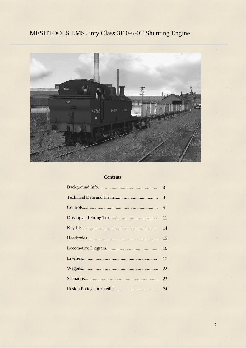
MESHTOOLS LMS Jinty Class 3F 0-6-0T Shunting Engine
Contents
Background Info....................................................
Technical Data and Trivia......................................
Controls..................................................................
Driving and Firing Tips.........................................
Key List.................................................................
Headcodes..............................................................
Locomotive Diagram.............................................
Liveries..................................................................
Wagons...................................................................
Scenarios................................................................
Reskin Policy and Credits......................................
3
4
5
11
14
15
16
17
22
23
24
3
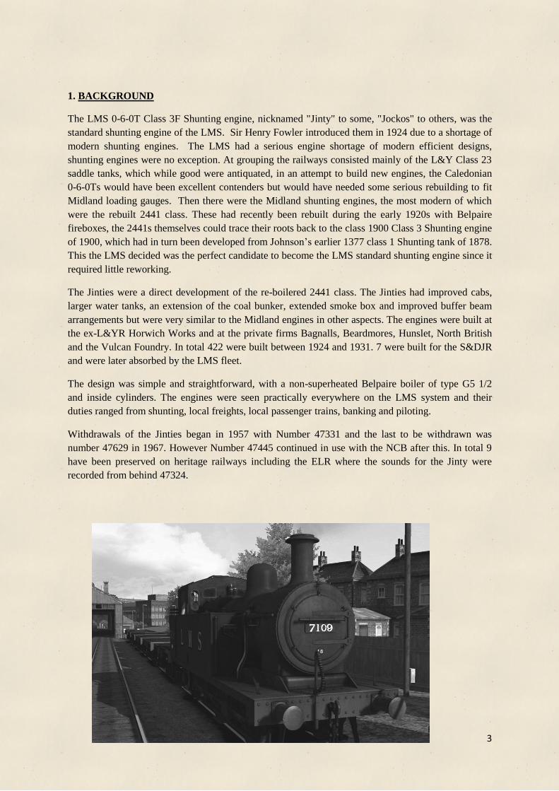
1. BACKGROUND
The LMS 0-6-0T Class 3F Shunting engine, nicknamed "Jinty" to some, "Jockos" to others, was the
standard shunting engine of the LMS. Sir Henry Fowler introduced them in 1924 due to a shortage of
modern shunting engines. The LMS had a serious engine shortage of modern efficient designs,
shunting engines were no exception. At grouping the railways consisted mainly of the L&Y Class 23
saddle tanks, which while good were antiquated, in an attempt to build new engines, the Caledonian
0-6-0Ts would have been excellent contenders but would have needed some serious rebuilding to fit
Midland loading gauges. Then there were the Midland shunting engines, the most modern of which
were the rebuilt 2441 class. These had recently been rebuilt during the early 1920s with Belpaire
fireboxes, the 2441s themselves could trace their roots back to the class 1900 Class 3 Shunting engine
of 1900, which had in turn been developed from Johnson’s earlier 1377 class 1 Shunting tank of 1878.
This the LMS decided was the perfect candidate to become the LMS standard shunting engine since it
required little reworking.
The Jinties were a direct development of the re-boilered 2441 class. The Jinties had improved cabs,
larger water tanks, an extension of the coal bunker, extended smoke box and improved buffer beam
arrangements but were very similar to the Midland engines in other aspects. The engines were built at
the ex-L&YR Horwich Works and at the private firms Bagnalls, Beardmores, Hunslet, North British
and the Vulcan Foundry. In total 422 were built between 1924 and 1931. 7 were built for the S&DJR
and were later absorbed by the LMS fleet.
The design was simple and straightforward, with a non-superheated Belpaire boiler of type G5 1/2
and inside cylinders. The engines were seen practically everywhere on the LMS system and their
duties ranged from shunting, local freights, local passenger trains, banking and piloting.
Withdrawals of the Jinties began in 1957 with Number 47331 and the last to be withdrawn was
number 47629 in 1967. However Number 47445 continued in use with the NCB after this. In total 9
have been preserved on heritage railways including the ELR where the sounds for the Jinty were
recorded from behind 47324.

4
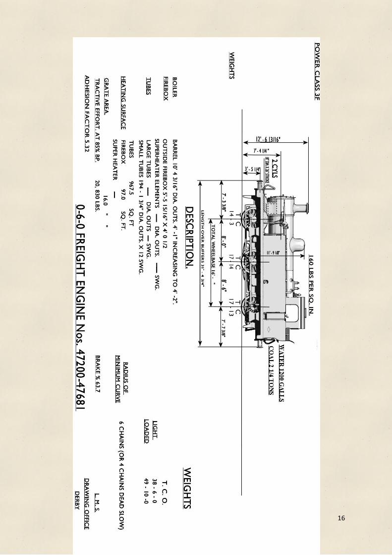
Technical data
Power Classification: 3F
Configuration: 0-6-0T
Total Built: 422
Length: 31'. 4.75"
Width: 8'.9"
Height: 12'. 6.81"
Weight: 49T. 10C
Coal Capacity: 2.25 Tons
Water Capacity: 1200 Gallons
Tractive Effort: 20835 Lbf
Estimated Power Output: 515HP
Fire tube heating surface: 967 Sq Ft
Firebox heating surface: 97 Sq Ft
Total Heating Surface: 1 074 Sq Ft
Cylinder Size 18' x 26'
Driver Diameter 4'. 7"
Boiler Pressure 160PSI
Trivia
In 1940, 8 Jinties were transferred to the War Department and were shipped to France, 5
returned and 3 were lost, presumed destroyed during the war. The French railways classified
them as 030 TW. One engine returned with a GWR Chimney (Presumably from a WD Dean
goods), another returned with a French pressure gauge with the red line at the equivalent of
227psi!
The seven engines built for the SDJR were fitted with screw reversers instead of the more
standard pole reverser, carriage warming apparatus and Whitaker tablet exchangers. They
were absorbed into the LMS in 1930 and in 1934 they were transferred to Saltey and Devon
Road. They were replaced on the SDJR by standard Jinties. On the SDJR they were used on
light passenger and freight workings, shunting and at any one time 3 or 4 were based at
Radstock for Banking goods trains up to Masbury summit as well as shunting in the area’s
collieries.
50 Jinties were built with steam brakes only.
Jinties were capable of speeds of up to 50mph and could occasionally reach 60mph.
The Jinties were liked by their crews, they could pull remarkably heavy loads for their size
and were able to stop smartly with fitted or unfitted trains, although they lacked the additional
brake force of the tender engines on unfitted trains.
The Jinties had enough coal bunker capacity to last 24 hours of normal shunting work
although the tanks would need replenishing 2 or 3 times in an 8 hour shift and the fire would
have to be cleaned every 8 hours on average.
5
18 17 4 15 16
1
5
3
10 9
11
12
14
13 8
6
2 7
19
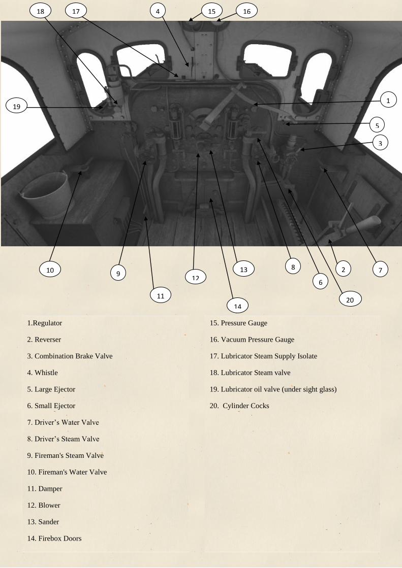
1.Regulator
2. Reverser
3. Combination Brake Valve
4. Whistle
5. Large Ejector
6. Small Ejector
7. Driver’s Water Valve
8. Driver’s Steam Valve
9. Fireman's Steam Valve
10. Fireman's Water Valve
11. Damper
12. Blower
13. Sander
14. Firebox Doors
15. Pressure Gauge
16. Vacuum Pressure Gauge
17. Lubricator Steam Supply Isolate
18. Lubricator Steam valve
19. Lubricator oil valve (under sight glass)
20. Cylinder Cocks
20

6
THE MODEL
We have created both a Standard (STD) and Advanced (ADV) version of each locomotive.
The need for both arose when creating the script as we found that the AI simply could not
drive the engine and some controls did not work via the HUD.
The advanced version includes advanced scripting which allows full simulation of the brake,
damage resulting from misuse, more accurate regulator and reverser. The locomotive
struggles to steam if over-fired so you have to keep a keen eye on the fire mass to ensure
optimum performance. This version is neither HUD compatible nor AI compatible.
The simple version is designed for users who do not want the intricacies of the advanced
features, having simplified control and more tolerant physics. This version is also AI
compatible unlike the advanced version.
All scenarios have an option to drive the standard or advanced versions, allowing drivers of
any skill to drive them without having any fuss and having to edit the scenarios themselves.
We have also included an AI version.
THE CONTROLS
Regulator
The regulator controls how much steam from the boiler enters the cylinders, the further it is
opened the faster you will accelerate. Be careful how much you open it since the engine may
slip. The regulator can be controlled by using the mouse or the A and D key to respectively
increase and decrease the regulator setting.
Note: To fully shut the regulator you may need to quickly open it then slam it shut.
Note: At low speeds the cylinder cocks may need to be opened, operated by pressing C, to
control the amount of steam entering the cylinders and prevent steam building up. If you open
the regulator while stationary and with the brake on you will need to open the cylinder cocks
before opening the regulator
Reverser
The reverser on the Jinty is of a pole design, it has 7 notches in either direction and a mid-
gear notch. It is fitted with a reverser lock which locks the reverser into a notch and prevents
it moving while the regulator is opened. To release the lock the E key must be used, but
caution must be used to not release the lock while the regulator is open more than a third
otherwise the reverser could fly into full forward or reverse taking your arm with it!
The reverser works by limiting the amount of steam which enters the cylinder and allows the
steam to expand more efficiently hence you will be able to go faster without emptying your
boiler and making the fireman rather grumpy. To move the reverser the W and S keys are
used to move it forward and back

7
Combination Brake Valve
The LMS combination brake enables a steam for the locomotive and vacuum for the train.
When the brake handle is moved towards the on position air is admitted into the train pipe
through a series of holes applying the brakes on the train, this however does not apply the
locomotives brakes. To apply the locomotives steam brake the brake valve also has a fulcrum
which balances the force of the vacuum piston pushing in and the steam pressure pushing out.
When vacuum is reduced the force pushing inwards is reduced until the point where the
steam pressure exceeds the force acting inwards (usually about 14-17" Hg) and the fulcrum is
thereby pushed out, when it is pushed out the exhaust port of the steam brake is shut allowing
steam to enter the pipe towards the steam brake cylinder applying the brake. When vacuum is
recreated the force inward increase and when the vacuum exceeds the range stated above the
fulcrum will move in shutting off steam to the brake cylinder and opening the exhaust port
venting the steam brake cylinder to the ash pan releasing the steam brake. It should be noted
therefore the steam brake application is not proportional to the vacuum brake application
unlike with BR Standard locomotives where the steam brake application is proportional.
However the fulcrum can be manipulated by hand, it's a bit awkward but the spindle can
actually be pulled out, or pushed in when the steam brake is being applied. As a result, the
steam brake pressure can be manipulated to an extent by pushing in and letting go of the
fulcrum allowing a partial application of the steam brake, not easy but you can do it. In
Brake handle
Cam
Vacuum piston
Fulcrum
Steam piston
Steam brake
exhaust to ashpan Steam pipe to
Brake
Cylinder
Train Pipe
Steam supply
for brake from
boiler
Hook
Vacuum "pepperpot" to prevent
vacuum rising above 21” Hg
To Brake
Gauge

8
addition to this, the brake valve has a cam attached to the handle which pushes the fulcrum
out should the vacuum piston stick.
To summarise, the brake can be applied in the following ways:-
• Destroying Vacuum below 17"
• Moving the brake handle towards the on position
• Manually pulling the fulcrum out
The locomotive brake can be released in the following ways:-
• Recreating vacuum above 17"
• By pushing vacuum spindle in manually with the handle in the off position
The brake valve also has a small hook built into it; this allows the steam brake to be pinned
off when the vacuum brake is applied, as should be done if standing for any length of time.
This can be achieved by pushing the spindle in (while brakes in the off position) and
manipulating the hook onto a small notch. The hook can also be used to hold the steam brake
on while vacuum is created, this can be achieved by pulling the fulcrum out and resting the
notch on the outside of the hook or by wedging a block of wood in or metal in –
unfortunately we can’t model this in game! When the brake valve is moved towards the on
position the hook should drop down allowing the brake to release or apply.
To operate the brakes:-
• The brake handle can be moved to on or off with : or '
• The fulcrum can be pushed in by pressing [
• The fulcrum can be pulled out by pressing ]
• The hook can be lifted up or down by pressing P
• Large ejector is U
• Small ejector is J / Shift J
Whistle
The spacebar will play a single toot of the whistle – there are a number of different short
whistles that are played with the spacebar.
Holding B will play a continuous long blast of the whistle
Ejectors
The Jinty is fitted with an SSJ type ejector produced by Gresham and Craven of Manchester.
It has a 20mm small ejector cone and a 25mm large ejector cone. The small ejector is more
9
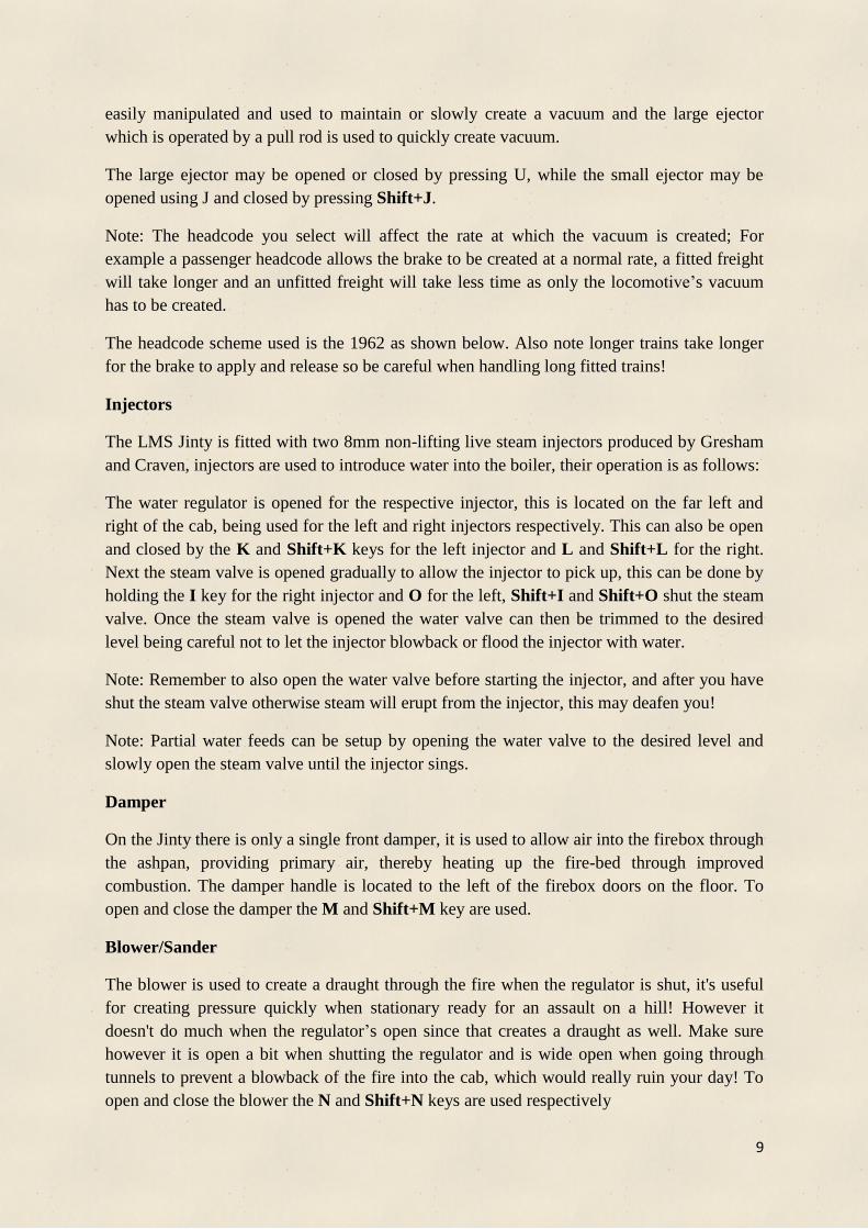
easily manipulated and used to maintain or slowly create a vacuum and the large ejector
which is operated by a pull rod is used to quickly create vacuum.
The large ejector may be opened or closed by pressing U, while the small ejector may be
opened using J and closed by pressing Shift+J.
Note: The headcode you select will affect the rate at which the vacuum is created; For
example a passenger headcode allows the brake to be created at a normal rate, a fitted freight
will take longer and an unfitted freight will take less time as only the locomotive’s vacuum
has to be created.
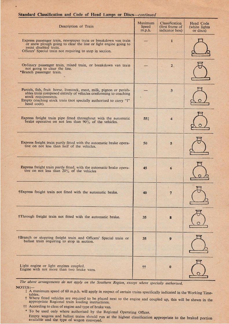
The headcode scheme used is the 1962 as shown below. Also note longer trains take longer
for the brake to apply and release so be careful when handling long fitted trains!
Injectors
The LMS Jinty is fitted with two 8mm non-lifting live steam injectors produced by Gresham
and Craven, injectors are used to introduce water into the boiler, their operation is as follows:
The water regulator is opened for the respective injector, this is located on the far left and
right of the cab, being used for the left and right injectors respectively. This can also be open
and closed by the K and Shift+K keys for the left injector and L and Shift+L for the right.
Next the steam valve is opened gradually to allow the injector to pick up, this can be done by
holding the I key for the right injector and O for the left, Shift+I and Shift+O shut the steam
valve. Once the steam valve is opened the water valve can then be trimmed to the desired
level being careful not to let the injector blowback or flood the injector with water.
Note: Remember to also open the water valve before starting the injector, and after you have
shut the steam valve otherwise steam will erupt from the injector, this may deafen you!
Note: Partial water feeds can be setup by opening the water valve to the desired level and
slowly open the steam valve until the injector sings.
Damper
On the Jinty there is only a single front damper, it is used to allow air into the firebox through
the ashpan, providing primary air, thereby heating up the fire-bed through improved
combustion. The damper handle is located to the left of the firebox doors on the floor. To
open and close the damper the M and Shift+M key are used.
Blower/Sander
The blower is used to create a draught through the fire when the regulator is shut, it's useful
for creating pressure quickly when stationary ready for an assault on a hill! However it
doesn't do much when the regulator’s open since that creates a draught as well. Make sure
however it is open a bit when shutting the regulator and is wide open when going through
tunnels to prevent a blowback of the fire into the cab, which would really ruin your day! To
open and close the blower the N and Shift+N keys are used respectively

10
The sander on the Jinty is bidirectional. Steam is used to force sand in front of or behind the
wheels. Sand aids adhesion in poor railhead conditions. The handle has three positions: Up
activates the forward sanders, horizontal stops both sanders and down activates the rear
sanders. To move the handle up the X key is used while to move the handle down the Shift X
key is used.
Note: There is only a limited amount of sand so use it sparingly. There is enough sand to last
for approximately 20 minutes in each direction so make sure you do not waste any!
Firebox Doors
Open and shut the doors with the F and Shift+F keys. It is probably wise to shut the firebox
doors when entering a tunnel to help prevent the fire blowing back into the cab. Just below
the doors is a flap which can be used to reduce the amount of air entering the fire and still
allow you to fire, this prevents the fire from cooling too much.
Gauges
The gauge on the left gives the boiler pressure in pounds per square inch, and the gauge on
the right will give you the vacuum brake pressure in inches of mercury.
Note: Ejectors failure will occur when boiler pressure drops below approximately 90psi.
Note: It is a requirement by law for 19" of Hg to be shown on the vacuum gauge when the
brakes are not being used, on a passenger service, make sure you are able to maintain this
level before starting off.
Hydrostatic Lubricator
The Jinty is fitted with a hydrostatic sight feed lubricator of the displacement type. It is used
to lubricate the engine’s slide valves and cylinders. It works by displacing oil by the use of
condensed steam which is regulated by an oil valve under a sight glass allowing the current
feed rate to be determined. To operate open the manifold steam valve to the horizontal
position and turn the steam valve to the right. The oil valve under the sight glass can be then
opened and the feed rate regulated. The usual rate is about 6 drops per minute. Please note
the lubricator will start working, but the oil valve will need to be opened more if you are
going to do any prolonged or fast movements. Problems may develop with the engine if the
correct amount of lubricant is not deposited.
Cylinder Cocks
The cylinder cocks allow any water droplets which have condensed in the cylinders to be
exhausted out of the cylinders thereby preventing damage. A secondary effect of the drain
cocks is that they aid the warming of the cylinders when the regulator is opened. They can be
found under the reverser pole. When you use the model the previous driver will have left the
cylinder cocks open to prevent the engine moving while it stands idle. This also prevents any
accidents should you forget to open the cylinder cocks yourself. The drain cocks should be

11
opened when starting from being stationary for a prolonged period of time and left in the
open position for around 5-6 revolutions of the wheels. They are controlled by the C key.
Other Controls
The locomotive’s handbrake may be applied by holding / or released by holding
Shift+/
The cab doors to the engine may be opened using the mouse
All the front windows can be opened using the mouse
The driver's seat may be moved using the mouse
The coal door near the floor at the back of the cab can be used to regulate the rate of
firing. To begin firing press R, to increase the rate of firing tap R until the desired
level is reached, to stop firing press Shift+R.
The gauge glass protectors may be rotated either way by use of the mouse to spin
them round.
The gauge glass isolating handles, the long handles on the outer sides of the glass, are
used to shut of the glass and prevent it refilling or blowing. Moving the handle down
isolates the gauge glass.
The gauge glass drain valve is located below the glass. To drain or test the water in
the glass the handle can be moved to the horizontal position where the water will
drain. Returning it will stop the glass draining.
The tank water level gauge moves depending on the water level inside of the tank.
The outside view works fully but the gauge in the cab view mode only gives a
indication of the water used since you started/ resumed the scenario and so should not
be judged to be totally accurate; this is due unsolvable scripting issues.
DRIVING TIPS
The Jinty is a unique engine, it requires skill to master but once you have you can send this thing
flying about like it's made of elastic. They key things which differentiate the Jinty from other engines
are the regulator, reverser and brakes.
Regulator
Watch out for the lag on the regulator, it may catch you out if you want to quickly shut off
steam
If going into second valve make sure you fully open and then slam the regulator shut.
At low speeds be careful of steam building up in the cylinders, use the cylinder cocks to help
keep the pressure in them steady.
Reverser
Remember the reverser has a latch on it, to move the reverser this must be disengaged.
Be careful not to move release the latch with the regulator open ; this could lead to some
unfortunate problems

12
There are many ways of driving an engine, my own method is to start in full gear, upon
reaching about 8mph shut of steam and notch back to notch 3, upon reaching about 20mph
notch back again to notch 2 and stay in that until about 35 mph where I notch back to notch 1.
If driving the standard version you will be able to move the reverser at will since the reverser
scripting is simplified.
Brakes
Remember when starting to have the brake fully off before opening the regulator
When making a brake application make a reduction to about 7" of Hg until the brakes bite at
which point the brake force can be manipulate by applying or destroying vacuum
To hold a steady vacuum put the brake into off and have the small ejector open a crack
Avoid the use of the large ejector except when stationary or if you are going to pull up too
soon
Do not stop with the vacuum brake fully applied passengers will not like it!
When handling fitted or unfitted trains make a light brake application or apply the locos
handbrake until all the wagons have bunched up before making a full brake application, this is
to prevent couplers snatching.
Try to stop with the brakes releasing with a pressure of about 12" Hg just as you pull up.
FIRING TIPS
The firing of Jinty will vary quite considerably depending whether you select the advanced or
standard version, generally the Advanced version is harder to fire and get right than the standard
version. The Standard version has the normal basic firing controls and can be used with the auto
fireman. The Advanced version is not compatible with the auto fireman and has more complex firing
controls.
Fire
The ideal "firemass" for the Jinty 530 lbs of coal, you should aim to keep the fire around that
mark.
The smoke colour will also give you an indication of the state of the fire, clear smoke
indicates either too much air or you need to add coal, black smoke indicates the fires got too
much coal on it and heats being wasted, if this occurs stop firing and open the fire doors and
put the flap up and let it burn through. Black smoke may also indicates too little air getting to
the fire, you may want to check whether your dampers open if you get black smoke.
Pale yellow/grey smoke indicates the fire isn't up to temperature.
Light grey smoke is ideal, when the smoke clears and the white of steam can be seen you can
now add coal, keep adding until the smoke goes grey and then close the fire doors.
The tactic of "little and often" does apply, do not put too much coal on the fire otherwise you
may ruin it.
If the boiler is generating more steam than is needed the damper may be shut, this will cool
the fire down and reduce steam generation, but be make sure you open again it advance of
needing more steam!
13
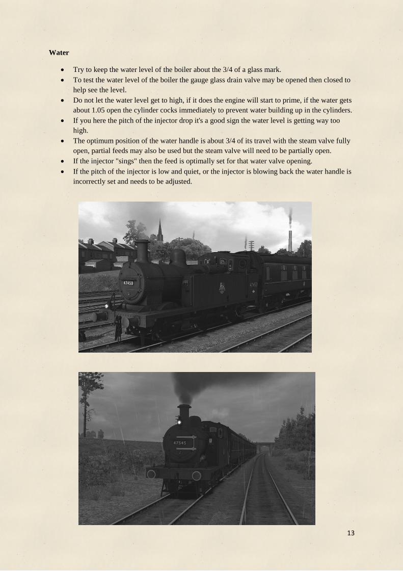
Water
Try to keep the water level of the boiler about the 3/4 of a glass mark.
To test the water level of the boiler the gauge glass drain valve may be opened then closed to
help see the level.
Do not let the water level get to high, if it does the engine will start to prime, if the water gets
about 1.05 open the cylinder cocks immediately to prevent water building up in the cylinders.
If you here the pitch of the injector drop it's a good sign the water level is getting way too
high.
The optimum position of the water handle is about 3/4 of its travel with the steam valve fully
open, partial feeds may also be used but the steam valve will need to be partially open.
If the injector "sings" then the feed is optimally set for that water valve opening.
If the pitch of the injector is low and quiet, or the injector is blowing back the water handle is
incorrectly set and needs to be adjusted.
14
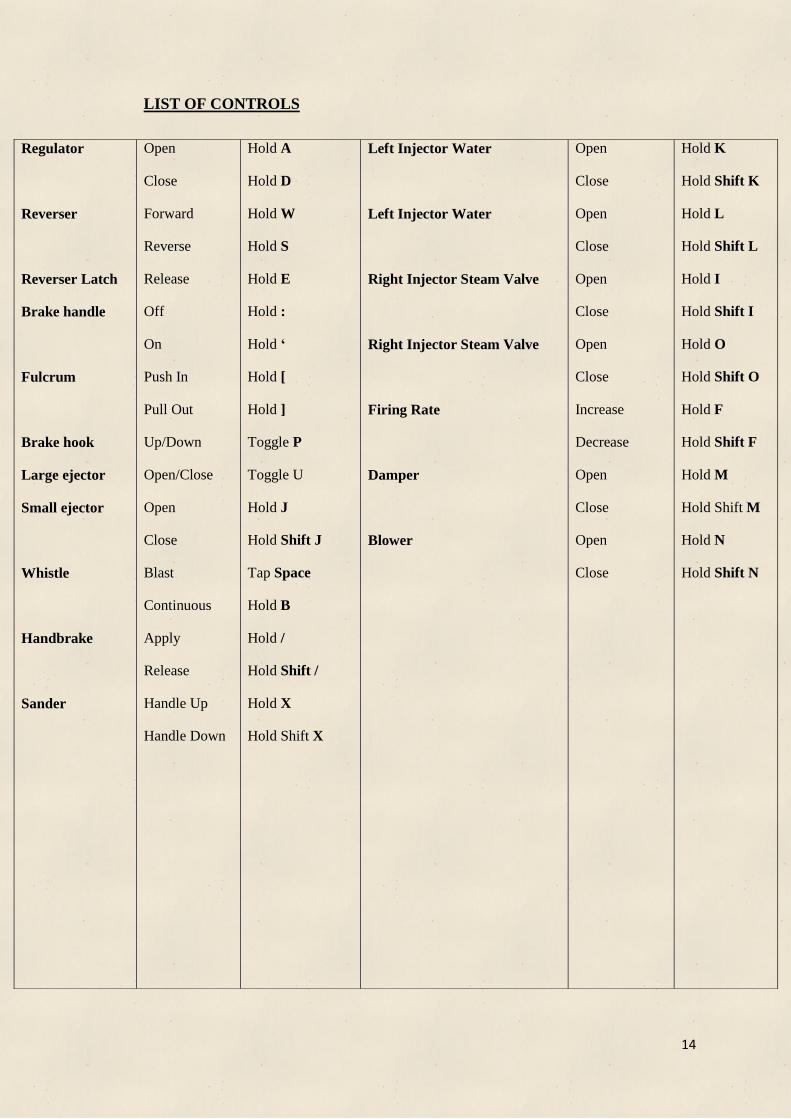
LIST OF CONTROLS
Regulator
Reverser
Reverser Latch
Brake handle
Fulcrum
Brake hook
Large ejector
Small ejector
Whistle
Handbrake
Sander
Open
Close
Forward
Reverse
Release
Off
On
Push In
Pull Out
Up/Down
Open/Close
Open
Close
Blast
Continuous
Apply
Release
Handle Up
Handle Down
Hold A
Hold D
Hold W
Hold S
Hold E
Hold :
Hold ‘
Hold [
Hold ]
Toggle P
Toggle U
Hold J
Hold Shift J
Tap Space
Hold B
Hold /
Hold Shift /
Hold X
Hold Shift X
Left Injector Water
Left Injector Water
Right Injector Steam Valve
Right Injector Steam Valve
Firing Rate
Damper
Blower
Open
Close
Open
Close
Open
Close
Open
Close
Increase
Decrease
Open
Close
Open
Close
Hold K
Hold Shift K
Hold L
Hold Shift L
Hold I
Hold Shift I
Hold O
Hold Shift O
Hold F
Hold Shift F
Hold M
Hold Shift M
Hold N
Hold Shift N
15
16

17
INCLUDED LIVERIES
Official Liveries
LMS Early ( 1924 – 1928 ) - This was the first standard freight engine livery and was
introduced from the formation of the LMS, it began to be phased out in 1928.
LMS Late ( 1928 – 1948 ) - This is the most typical livery of the later LMS period. This
style began to be applied in 1928 and had several variations. Our livery most accurately
represents the initial 1928 style of font with most engines carrying it until nationalisation.

18
BR Early ( 1948-1950) - This livery first began being applied in 1948, however not all
engines received it many carrying their old LMS liveries, it began to be phased out in mid
1949 however some engines carried it into the 50's.
BR Mid ( 1950 – 1956 ) - This livery replaced the earlier style with most if not all the class
receiving it. This livery features the BR 'monocycling lion' and lasted until the late 1950's.
19
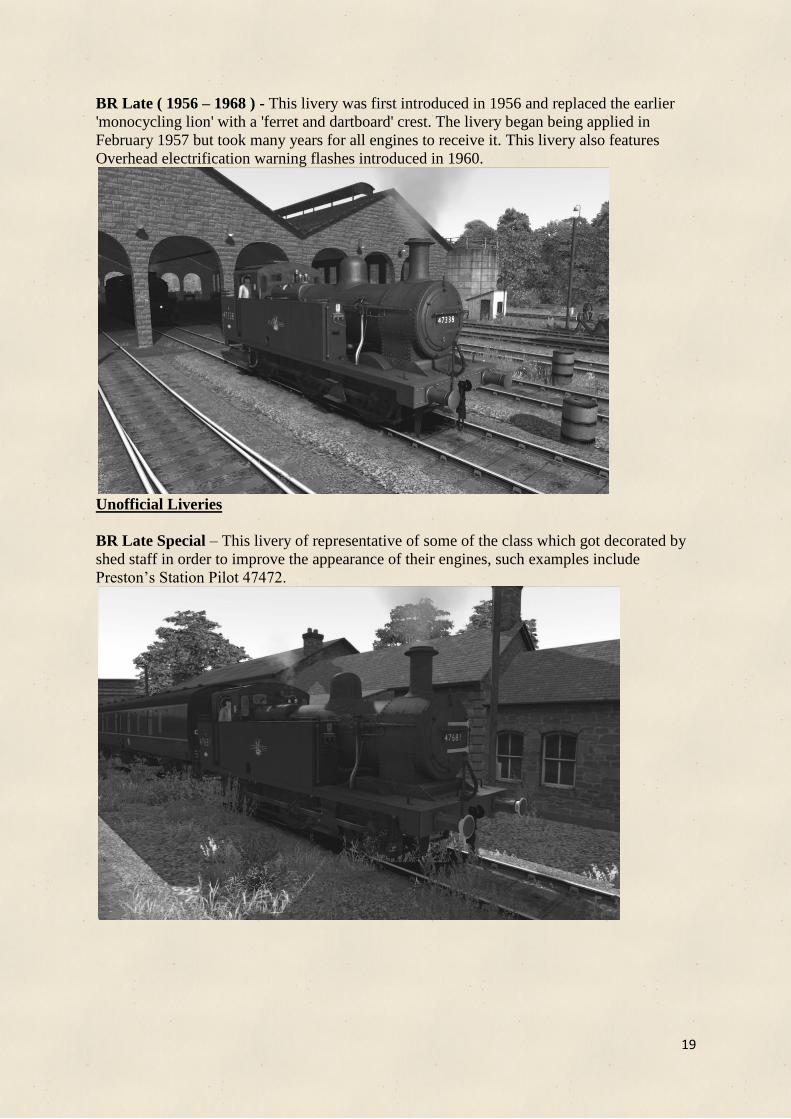
BR Late ( 1956 – 1968 ) - This livery was first introduced in 1956 and replaced the earlier
'monocycling lion' with a 'ferret and dartboard' crest. The livery began being applied in
February 1957 but took many years for all engines to receive it. This livery also features
Overhead electrification warning flashes introduced in 1960.
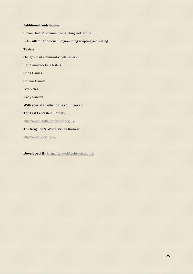
Unofficial Liveries
BR Late Special – This livery of representative of some of the class which got decorated by
shed staff in order to improve the appearance of their engines, such examples include
Preston’s Station Pilot 47472.

20
NCB This livery represents 47445 which was purchased by the National Coal Board in 1967
for work at one of its collieries near Wakefield. Note: This engine is steam brake only.
Note: BR Mid also has a steam brake only version. This is representative of the 50 engines
built without any vacuum brakes.

21
Note: Numbering scheme:
The locomotive number can be altered in the scenario editor. Once the loco has been placed
double clicking on the engine will bring out a pop out on the right side of the screen, the loco
number may be entered into the box in the format shown below:
LMS Early: 18#16414 - First two digits are the 2 digit shed code , last 5 digits are the
locomotives number.
LMS Late: 18#7405 - First two digits are the 2 digit shed code, last 5 digits are the
locomotives number.
BR Liveries: D26#47324 - First Letter is the letter of the shed code, next 2 digits are the
shed code number, last 5 digits are the locomotives number
NCB: A00#47445 - First 3 digits are unused, last 5 digits are the locomotives number.
Wagons: 419599 - Wagon numbers may be altered in a similar way. The 6 digits are the
wagons number.
Note : On the same pop out the initial water and coal levels can be selected as a % of their
respective maximum ( 1200 gallons of water and 2.25 Tons of coal ).
Loco number In here
Initial Water
Level
Initial Coal Level

22
WAGONS
The wagons included are variants of LMS 12T open and LMS 12T covered wagons. Each
version includes a fitted and unfitted version. Each of the open wagons include loaded variant
which can either be filled with gravel, milk churns or general goods covered with a tarpaulin.
Please note that due to the way the setup wagons it is not possible to load wagons during a
scenario, they can only be placed loaded or unloaded. The pack also contains a brake van of
the BR Diagram 506 and is fitted with vacuum brakes.
LMS 12T Open Wagons
LMS 12T Covered Vans
BR 20T Brake van

23
SCENARIOS
Intro A basic scenario giving you an introduction in how to operate the locomotive,
there are some interesting new features you may want to look at and learn how
to use! This scenario is only available for the Advanced [ADV] version of the
locomotive. Have an easy drive with some wagons to Dumfries. This is a
good time to learn and get used to the controls.
Days Duty Today you will be running a local passenger service, but first you have a few
shunting tasks you’ll need to complete. There are Mk1 coaches all over the
place and you'll need to shunt them together for a later express services.
You’ll be driving to Newton Stewart stopping at all stations.
Shuffling You have a long schedule ahead of you, with quite a few shunting tasks. Take
your time and keep checking your task list for instructions. There are lots of
wagons scattered around in sidings and they need organising, as well as a
number of Mk1s which need to be prepared for service.
The Local Haul Some light shunting tasks and a short run to Dalbeattie. Keep your eye on
your task list and keep a look out for other services on and about the line.
The Local Service The local passenger service to Kirkcudbright stopping at all stations with a
strict timetable to stick to. Make sure you stick to the schedule so you can
make it to the stations on time. Good luck!
All scenarios, except the first, support the standard and advanced versions, they are defined using
[Std] for Standard and [Adv] for Advanced.

24
Reskinning/Sound Policy
Our (Meshtools) re-skin policy for the Jinty add-on is as follows:
We generally allow re-skins of our work to be done. Permission needs to be sought prior to
the creation of the re-skin. Contact us at Meshtools by filling in a support form on our
website at http://www.meshtools.co.uk/contact ,
We would also like for you to inform us how your re-skin is going and if any improvements
can be made to make re-skinning easier. Approval should also be sought before uploading it
to any site.
The re-skins must not include the shape files, child object files, simulation files, script files,
sound files or animation files, but it can include the loco bins if needed.
No modifications to any of the sounds is permitted, any sound modifications must be done
from scratch and not based on the included sound files, this includes both .xml and .bin file.
Sound modifications must not use or include any audio files such as .wav or .dav files
included with the add-on.
THANK YOU
Meshtools would like to thank you for buying the Jinty model. We hope you enjoy driving it, should
you have any problems please contact us through the contacts page on our website at:
www.meshtools.co.uk
Please feel free to suggest any improvements that could be made either for this or future add-ons.
CREDITS
Thank you to all those who those who helped out, contributed and gave their own time to this project!
Without them it would not be possible to release this model to you.
Also, thank you for taking some time to go through and read this manual, we hoped it helped answer
some of your questions or any problems you’ve been having! I’d also personally like to thank you for
purchasing this addon and supporting us. We hope to bring you a lot more exciting add-ons in the
future!
Major contributors:
Michael Whiteley: 3D modelling, texturing, animation, route building, scenarios, research and live
steams.
Edward Fisk: Sounds, simulation/physics, scripting, quality control, support, research and live
streams.
RailSimulator.com: support, publishing and testing.
25
Additional contributors:
Simon Hall: Programming/scripting and testing.
Pete Gillam: Additional Programming/scripting and testing.
Testers:
Our group of enthusiastic beta testers!
Rail Simulator beta testers
Chris Barnes
Connor Barrett
Ben Yates
Andy Lawton
With special thanks to the volunteers of:
The East Lancashire Railway
http://www.eastlancsrailway.org.uk/
The Keighley & Worth Valley Railway
http://www.kwvr.co.uk/
Developed By http://www.Meshtools.co.uk