Mesh-Intro 14.5 L07 Assembly Meshing
32
© 2012 ANSYS, Inc. January 15, 2013 1 Release 14.5 14. 5 Release Introduction to ANSYS Meshing Lecture 7 Assembly Meshing
description
ansys workbench
Transcript of Mesh-Intro 14.5 L07 Assembly Meshing

© 2012 ANSYS, Inc. January 15, 2013 1 Release 14.5
14. 5 Release
Introduction to ANSYS Meshing
Lecture 7 Assembly Meshing

© 2012 ANSYS, Inc. January 15, 2013 2 Release 14.5
What you will learn from this presentation
• Concept of Assembly Meshing
• Assembly Meshing Methods
– CutCell
– Tetra
• Controls
• Virtual Bodies
• Fluid Surfaces
• Contacts
• Sharp Angle Tool
• Leakage
Assembly Meshing

© 2012 ANSYS, Inc. January 15, 2013 3 Release 14.5
Preprocessing Workflow
Sketches and
Planes
Geometry Import
Options
3D Operations
Direct CAD/Bi-
Directional CAD
Geometry
Cleanup and
Repair
Automatic
Cleanup
Merge, Connect,
Projection, Flow
Volume
Extraction, etc
Extrude, Revolve,
Sweep, etc
3D Operations
Boolean, Body
Operations, Split,
etc
Meshing
Methods
Hybrid Mesh: Tet,
Prisms, Pyramids
Hexa Dominant,
Sweep meshing
Global Mesh
Settings
Local Mesh
Settings
Sizing,
Body/Sphere of
Influence, Match
Control, etc
Geometry Creation OR
Geometry Import
Geometry Operations
Meshing Solver
Assembly
Meshing

© 2012 ANSYS, Inc. January 15, 2013 4 Release 14.5
Meshing Process in ANSYS Meshing (Assembly Meshing)

© 2012 ANSYS, Inc. January 15, 2013 5 Release 14.5
Behavior
• Meshes an entire model as single process
– Mesh Methods covered so far are part or body based methods
– Not compatible with part/body methods
• Two Algorithms available
– CutCell & Tetrahedrons
Access
• Assembly Meshing is accessible only when Physics and Solver Preferences are set to CFD and Fluent respectively
• To activate, replace None by Cutcell or Tetrahedrons
Assembly Meshing

© 2012 ANSYS, Inc. January 15, 2013 6 Release 14.5
• Operates on parts, multi-body parts, etc.
– Tolerates overlapping bodies
• Creates conformal meshes across parts in contact
– Eliminates the need for multi-body part generation in CAD
• Ability to define Virtual Bodies for fluid flow from a “closed” set of bodies (sheet or solid)
– Eliminates the need for Boolean/Fill operations in CAD
• Patch Independent
– Eliminates the need for pinch control and VT operations
• Mesh elements size driven by Size Functions
Assembly Meshing - Characteristics
Note that some global and local controls are
not available for Assembly Meshing (eg.
Match Control)
CutCell Assembly Mesh

© 2012 ANSYS, Inc. January 15, 2013 7 Release 14.5
CutCell Behavior
• Cartesian meshing method designed for the ANSYS FLUENT solver
• Generates a majority of hex cells
– Some wedges, tets and pyramids at boundaries to capture geometry
– During transfer to Fluent hexa cells at size transition are converted into Polyhedra
• Supports Inflation
– Post-inflation (TGrid algorithm)
• Inflation on zero thickness baffles not supported
• Thick inflation layers may fail
– Cutcell mesh generated first, inflation generated second (Post)
Assembly Meshing - CutCell

© 2012 ANSYS, Inc. January 15, 2013 8 Release 14.5
Tetrahedrons Behavior
• Generates a Patch Independent tetra mesh with automatic defeaturing
• Following steps occur in background
– Generate CutCell
– Delete volume mesh
– Triangulate surface mesh and improve
– Fill with tetra mesh
• Compatible with inflation
– Pre-inflation
• Algorithm similar to Tetra Patch Conformal
• Has the benefits of cutcell (no requirement on solid bodies, patch independent, etc) but with the flexibility of the bottom up approach i.e. “pre” inflation rather than post
Assembly Meshing - Tetrahedrons

© 2012 ANSYS, Inc. January 15, 2013 9 Release 14.5
• Set Advanced Size Functions
– Proximity SF Sources : 'edges', ‘faces’ or ‘edges and faces’
– ‘Faces’ is v. expensive and edges is recommended
– Define correct Min Size (details next slide)
• Inflation defined by Global or Local controls
– Combined Global & Local not supported
– Program Control acts on Fluid bodies only
• Bodies can be set as Fluid in Body properties
– For Virtual Bodies, only automatic Program Controlled inflation can be used (wetted surfaces may only be defined during meshing)
• Define Feature and Tessellation controls (see next slide)
• Apply any required local size controls
• Statistics
– Use Orthogonal Quality for Cutcell meshes
Assembly Meshing - Controls

© 2012 ANSYS, Inc. January 15, 2013 10 Release 14.5
Min Size definition
• Assembly Meshing is Patch Independent and starts with a Cartesian overlaid grid which finds closed regions
• Geometry recovery and leakage between regions depend on local sizes, i.e. if Cartesian size is too small near a gap you will get leakage between regions
• Local sizes are driven by Size Function definitions
– ‘Min Size’ and ‘Prox Min Size’ must be set with care
– Prox Min Size can be smaller than Min Size to avoid over-refinement in curved areas
• Local mesh size recommendation to capture 3D features
– Local size < ½ important feature size
• Local mesh size recommendation to close gaps
– 1/10 local mesh size < gap size < ¼ local mesh size : apply hard sizing to force gap closed
– Gap size < 1/10 local mesh size : gap closed
Assembly Meshing - Controls
Example2 . Doubling
the Min Size closes the
gap
Example 1. Min Size
too large compared to
the size of the
geometric detail

© 2012 ANSYS, Inc. January 15, 2013 11 Release 14.5
• Feature Capture
– Program Controlled : default which sets feature angle = 40
– Feature Angle : user defined angle to define feature level to recover
• 0 to capture all curves in model
• Tessellation (faceting) refinement
– Assembly meshing is applied to a faceted representation of the geometry via TGrid libraries
– Program Controlled - default which sets tessellation refinement to 10% of the value of smallest mesh size
– Absolute Tolerance – user defined tolerance
• Must be set to 5-10% of smallest mesh size
– None - Sets tessellation to the CAD program or Design Modeler default setting
• Note DM faceting control is in Options GraphicsDesign Modeler Graphics Facet Quality
Assembly Meshing - Controls
Tessellation problems may
lead to leakage

© 2012 ANSYS, Inc. January 15, 2013 12 Release 14.5
• Images above show the tessellated representation of the geometry in the workshop which is passed to the TGrid libraries for cutcell meshing
• With no refinement the geometry is coarsely faceted but with the recommended refinement of 0.1*min-size a good curvature of geometry is captured and will give better geometric fidelity in the mesh
Tessellation Refinement
Tess. Ref. = None Tess. Ref. = 0.1mm
© 2012 ANSYS, Inc. January 15, 2013 13 Release 14.5
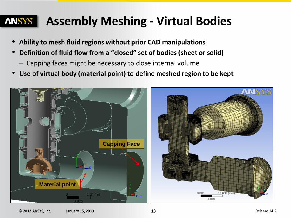
Assembly Meshing - Virtual Bodies
• Ability to mesh fluid regions without prior CAD manipulations
• Definition of fluid flow from a “closed” set of bodies (sheet or solid)
– Capping faces might be necessary to close internal volume
• Use of virtual body (material point) to define meshed region to be kept
Material point
Capping Face

© 2012 ANSYS, Inc. January 15, 2013 14 Release 14.5
Assembly Meshing - Virtual Bodies
1
Using Virtual Bodies
1. Define a new Coordinate System inside the Fluid Void
– Easy creation based on entity selection, e.g. Select 2 points, RMB > Create Coordinate System
2. RMB on Geometry and Insert a Virtual Body
3. Assign the Coordinate System to the Material Point in the details of the Virtual Body
2
3 Material
Point

© 2012 ANSYS, Inc. January 15, 2013 15 Release 14.5
Assembly Meshing - Virtual Bodies
Using Virtual Bodies
• When using Virtual Bodies, user can choose to keep or discard the solid mesh
• ‘Keep Solid Mesh’ option in the global controls

© 2012 ANSYS, Inc. January 15, 2013 16 Release 14.5
Assembly Meshing - Fluid Surfaces Creating Fluid Surfaces for Virtual Bodies
• Description
– If possible, the user can improve robustness by picking all faces that make up the wetted surfaces of the flow volume
• Can take advantage of “Extend to Connection” (see appendix)
– Only specified fluid surface faces will be used for mesh generation (solids ignored)
• Applications
– Used when only flow volume is needed
• ‘Keep Solid Mesh’ NO
• Advantages
– Faster
– Less memory
– Reduction of leakages
– Reduction of unnecessary refinement
• Usage
– Fluid Surfaces will ignore baffles
– Fluid surfaces recommended when Virtual Body is bounded by surface bodies only

© 2012 ANSYS, Inc. January 15, 2013 17 Release 14.5
Assembly Meshing - Sharp Angle Tool
• A special cell cutting algorithm has been developed to properly capture sharp 3D angles
• Can be used to improve feature capturing in general
• Similar to “thin cuts” in ICEM CFD
• Right click on Mesh, Insert ‘Sharp Angle’.
• Select surfaces adjacent to edges at sharp locations. Can select multiple areas.
Sharp angles in the Flow volume of a drill bit model
Mesh without Sharp Angle Tool
Mesh with Sharp Angle Tool

© 2012 ANSYS, Inc. January 15, 2013 18 Release 14.5
Find leaks using material points
• When using material points (for internal flow) and the mesh is leaking to the outside, the leak-path will be automatically displayed together with the surface mesh. User can try to repair gap/hole based on path.
Assembly Meshing - Leakage Path
Example; Gap between pipe flange surfaces. Message indicates leakage. Leakage path displayed in Graphics Window.

© 2012 ANSYS, Inc. January 15, 2013 19 Release 14.5
Contents
• Contacts
• Sharp Angle Notes
• Mesh Groups
• Important General Notes
Appendix

© 2012 ANSYS, Inc. January 15, 2013 20 Release 14.5
Using Contacts for Assembly Meshing
• Workbench has extensive capabilities with respect to the detection of contacts (interfaces or connections) between parts
• When meshing intersecting bodies using assembly meshing, the intersection lines can have poor feature capture
• Assembly Meshing Contact Tools
– Find Contacts
• Features at contact pairs will be well preserved in the mesh
• Enable use of ‘Extend to Connection’ selection tool
– Find Thin Sections
• Check thin bodies to set a corresponding size
– Closing of small gaps using Contact Sizing
Assembly Meshing - Contacts
For example, in this image the circled edges would be removed without contact defined since the feature angle is below the default (40 degrees)

© 2012 ANSYS, Inc. January 15, 2013 21 Release 14.5
Assembly Meshing - Contacts
Finding Contacts
• By default connections are created automatically in WB, so to start with delete all the old connections
• To create contacts, RMB on Mesh and ‘Find Contacts’
– This will generate contacts for the whole assembly
• Face - Edge and/or Face – Face
– Make sure Size Functions and min-size are set to appropriate levels for the geometry
© 2012 ANSYS, Inc. January 15, 2013 22 Release 14.5
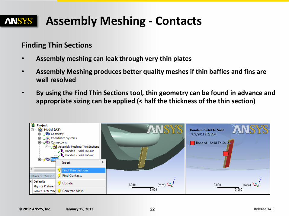
Finding Thin Sections
• Assembly meshing can leak through very thin plates
• Assembly Meshing produces better quality meshes if thin baffles and fins are well resolved
• By using the Find Thin Sections tool, thin geometry can be found in advance and appropriate sizing can be applied (< half the thickness of the thin section)
Assembly Meshing - Contacts

© 2012 ANSYS, Inc. January 15, 2013 23 Release 14.5
Assembly Meshing - Contacts
#1
#2
#3
Defining Contact Sizings
• Contact Sizings can be used to avoid leaks between parts
– Closing Gaps smaller than ~¼ of min size
• How to set Contact Sizings 1. Insert a contact with the entities
between which there is a gap • Face/Face or Face/Edge
2. Drag and drop the contact on top of the Mesh Icon • Creates a Contact sizing
3. Adjust Contact sizing • Should be bigger than the gap
4. Generate Mesh
Example; Pick the face of the valve plug (blue) and the edge of the valve seat (red)
© 2012 ANSYS, Inc. January 15, 2013 24 Release 14.5
Assembly Meshing - Contacts
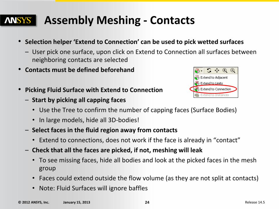
• Selection helper ‘Extend to Connection’ can be used to pick wetted surfaces
– User pick one surface, upon click on Extend to Connection all surfaces between neighboring contacts are selected
• Contacts must be defined beforehand
• Picking Fluid Surface with Extend to Connection
– Start by picking all capping faces
• Use the Tree to confirm the number of capping faces (Surface Bodies)
• In large models, hide all 3D-bodies!
– Select faces in the fluid region away from contacts
• Extend to connections, does not work if the face is already in “contact”
– Check that all the faces are picked, if not, meshing will leak
• To see missing faces, hide all bodies and look at the picked faces in the mesh group
• Faces could extend outside the flow volume (as they are not split at contacts)
• Note: Fluid Surfaces will ignore baffles

© 2012 ANSYS, Inc. January 15, 2013 25 Release 14.5
This should
be resolved in
the CAD
Contact Sizing Limitations
• The features at a Face-Face location are often not well resolved since there are not features on both side of the gap
• Avoid using inflation at contact size locations
– Exclude the faces around the gap using Named selection
• Do not combine Contact sizing with sharp angle tool
– Contact sizing tries to “walk over” thin gaps
– Sharp angle tools try to resolve small gaps
Assembly Meshing - Contacts
No Feature Features

© 2012 ANSYS, Inc. January 15, 2013 26 Release 14.5
• Sharp angle tools does not work in following cases
– Between baffles
– In combination with contact sizing
• Using sharp angle tool can lead to reduced quality
– Ignoring inflation at sharp angle faces often improves quality
• Sharp angle tool to resolve thin plates
– If you have a big thin plate and only edge proximity size function, CutCell might fail and leak right through the plate
– However, instead of resolving the plate using face proximity (which is time consuming), you can add sharp angle tool on both side of the plate
• Note that if the plate is meshed, the ends need to be well resolved
Assembly Meshing - Sharp Angle Notes

© 2012 ANSYS, Inc. January 15, 2013 27 Release 14.5
Without sharp angle tool
With sharp angle tool
Assembly Meshing - Sharp Angle Notes
very thin plate

© 2012 ANSYS, Inc. January 15, 2013 28 Release 14.5
Using Mesh Groups
• Mesh Groups can be defined to identify bodies that should be grouped together for assembly meshing algorithms
• This approach may be useful if the fluid domain was decomposed into multiple volumes
• With CutCell, decomposed volumes are no longer needed. Grouping tells the mesher to treat certain solid parts as one part
• The mesh generated on the combined parts (i.e., the group) will be associated with the mesh of the selected master body
Assembly Meshing - Mesh Groups

© 2012 ANSYS, Inc. January 15, 2013 29 Release 14.5
• Cannot be used in combination with other Meshing Methods
• Feature recovery limitations
– Sharp trailing edges and acute edges will produce a jagged mesh
– Recovering some features might lead to bad quality
• Prior to meshing the user is advised to resolve geometry features properly CAD/DM
– Avoid unnecessary geometry details
– Min size should be ½ of smallest 3D feature, check and adjust if required
• Interoperability
– Inflation not supported on baffles or internal walls
– Ignored symmetry condition for meshing
• Failure in the CutCell meshing algorithm is almost always related to faceting issues in relation to the value of Min Size. Make sure that the value of Min Size truly represents the smallest size that you want the curvature and proximity size function to capture
Assembly Meshing – Important General Notes

© 2012 ANSYS, Inc. January 15, 2013 30 Release 14.5
• ANSYS Meshing Gives the Warning: “The tolerance of the geometry is larger than the applied tessellation refinement tolerance. This might lead to an uneven mesh and/or to poor geometric accuracy of the mesh.”
• Background: For assembly meshing a tessellated version of the geometry is generated and passed to TGrid libraries where the mesh is generated. This is very much like an STL representation.
• Meaning of warning: In certain models, some CAD curves may not accurately follow the topologically connected surface(s). The warning above happens when the tolerance describing the mismatch between curves and surfaces is greater than the refinement tolerance. This mismatch can lead to holes being created in the faceting.
• A post-tessellation refinement “hole-fixing algorithm” subsequently tries to patch any holes created with an algorithm but hole closing itself can lead to poor representation of the geometry. Hole closing can also fail, leading to leakage in the Assembly Meshing algorithms (cutcell and tetrahedra) inside ANSYS Meshing.
• Example given on next slide.
Assembly Meshing – Common Warning 1

© 2012 ANSYS, Inc. January 15, 2013 31 Release 14.5
2. Tessellation Refinement will refine
facets to improve situation but can open
holes
1. No Tessellation Refinement – sloppy
CAD surfs don’t match curves
3. Hole fix step done automatically after
tessellation refinement can distort
geometry or fail leaving holes, causing
cutcell to “leak”
Hole opened
Hole Fixed
Assembly Meshing – Common Warning 2

© 2012 ANSYS, Inc. January 15, 2013 32 Release 14.5
• What can the user do about it?
• This is a warning only and it may be that there are no ill effects caused by it – patches could all be very clean. Check the final mesh.
• User should inspect their geometry to check for problems around areas of curvature and fix if possible. Use CAD/DM to simplify.
• Do not use merging operations for faces in DM for Assembly Meshing – it is patch independent and these are not required.
• Do not use virtual topology for Assembly Meshing for the same reason.
• Usually poor quality will show up if this is a problem or there will be some poor feature capture
• If cutcell “leaks” and the final surfaces of the mesh look nothing like the original geometry try switching off refinement to see if this helps and then trying larger user defined tolerances (recommend 1/10th min size in the mesh)
Assembly Meshing – Common Warning 3