Mercury Marine 2003 - Brunswick Marine in...
97
90-10132040 203 Jet 20 2003 Mercury Marine President, Mercury Marine, Fond du Lac, WI USA European Regulations Contact: Product Environmental Engineering Department, Mercury Marine, Fond du Lac, WI USA Patrick C. Mackey If the outboard motor’s serial number plate contains the CE mark in the low- er left-hand corner, the following statement applies: This outboard motor manufactured by Mercury Marine, Fond du Lac, Wis- consin, USA or Marine Power Europe Inc. Park Industriel, de Petit-Re- chain, Belgium complies with the requirements of the following directives and standards, as amended: Recreational Craft Directive: 94/25/EC; std. ISO 8665, ISO 11547 Machinery Directive: 98/37/EC, EMC Directive: 89/336/EC; std. EN50081-1, SAE J551 (CISPR Pub. 12), EN 50082-1, IEC 61000 PT4-2, IEC 61000 PT4-3
Transcript of Mercury Marine 2003 - Brunswick Marine in...
90-1
0132
040
203
Jet
20
2003
M
ercu
ry M
arin
e
President, Mercury Marine, Fond du Lac, WI USA
European Regulations Contact:Product Environmental Engineering Department, Mercury Marine, Fond du Lac, WI USA
Patrick C. Mackey
If the outboard motor’s serial number plate contains the CE mark in the low-er left-hand corner, the following statement applies:
This outboard motor manufactured by Mercury Marine, Fond du Lac, Wis-consin, USA or Marine Power Europe Inc. Park Industriel, de Petit-Re-chain, Belgium complies with the requirements of the following directivesand standards, as amended:
Recreational Craft Directive: 94/25/EC; std. ISO 8665,ISO 11547
Machinery Directive: 98/37/EC,EMC Directive: 89/336/EC; std. EN50081-1,
SAE J551 (CISPR Pub. 12),EN 50082-1, IEC 61000 PT4-2,IEC 61000 PT4-3
0
Thank YouFor your purchase of one of the finest outboards available. You have made a soundinvestment in boating pleasure. Your outboard has been manufactured by MercuryMarine, a world leader in marine technology and outboard manufacturing since1939. These years of experience have been committed to the goal of producing thefinest quality products. This led to Mercury Marine’s reputation for strict qualitycontrol, excellence, durability, lasting performance and being the best at providingafter-the-sale support.
Please read this manual carefully before operating your outboard. This manual hasbeen prepared to assist you in the operation, safe use and care of your outboard.
All of us at Mercury Marine took pride in building your outboard and wish you manyyears of happy and safe boating.
Again, thank you for your confidence in Mercury Marine.
Warranty MessageThe product you have purchased comes with a limited warranty from MercuryMarine, the terms of the warranty are set forth in the Warranty Information Sectionof this manual. The warranty statement contains a description of what is covered,what is not covered, the duration of coverage, how to best obtain warranty coverage,important disclaimers and limitations of damages, and other related information.Please review this important information.

1
oa
TABLE OF CONTENTS
Warranty Information
Transfer of Warranty 5. . . . . . . . . . . . . . . . . . . . . . . . . . . . . . . . . . . . . . . . . . . . . . . . . .
Warranty Registration
United States and Canada 6. . . . . . . . . . . . . . . . . . . . . . . . . . . . . . . . . . . . . . . . . . .
Outside United States and Canada 7. . . . . . . . . . . . . . . . . . . . . . . . . . . . . . . . . . .
Outboard Limited Warranty 8. . . . . . . . . . . . . . . . . . . . . . . . . . . . . . . . . . . . . . . . . . . . .
3 Year Limited Warranty against Corrosion 10. . . . . . . . . . . . . . . . . . . . . . . . . . . . . .
Warranty Coverage and Exclusions 12. . . . . . . . . . . . . . . . . . . . . . . . . . . . . . . . . . . .
General Information
Boater’s Responsibilities 14. . . . . . . . . . . . . . . . . . . . . . . . . . . . . . . . . . . . . . . . . . .
Before Operating Your Outboard 15. . . . . . . . . . . . . . . . . . . . . . . . . . . . . . . . . . . .
Recording Serial Number 15. . . . . . . . . . . . . . . . . . . . . . . . . . . . . . . . . . . . . . . . . . .
Boat Horsepower Capacity 16. . . . . . . . . . . . . . . . . . . . . . . . . . . . . . . . . . . . . . . . .
Outboard Remote Control (If Equipped) 17. . . . . . . . . . . . . . . . . . . . . . . . . . . . . .
Remote Steering Notice 17. . . . . . . . . . . . . . . . . . . . . . . . . . . . . . . . . . . . . . . . . . . .
Lanyard Stop Switch 18. . . . . . . . . . . . . . . . . . . . . . . . . . . . . . . . . . . . . . . . . . . . . . .
Stopping The Boat In an Emergency 20. . . . . . . . . . . . . . . . . . . . . . . . . . . . . . . . .
Protecting People In The Water 21. . . . . . . . . . . . . . . . . . . . . . . . . . . . . . . . . . . . .
Wave and Wake Jumping 22. . . . . . . . . . . . . . . . . . . . . . . . . . . . . . . . . . . . . . . . . .
Exhaust Emissions 23. . . . . . . . . . . . . . . . . . . . . . . . . . . . . . . . . . . . . . . . . . . . . . . .
Selecting Accessories For Your Outboard 25. . . . . . . . . . . . . . . . . . . . . . . . . . . . .
Safe Boating Suggestions 25. . . . . . . . . . . . . . . . . . . . . . . . . . . . . . . . . . . . . . . . . .
Specifications 28. . . . . . . . . . . . . . . . . . . . . . . . . . . . . . . . . . . . . . . . . . . . . . . . . . . . .
Installation
Installing Outboard On The Transom 29. . . . . . . . . . . . . . . . . . . . . . . . . . . . . . . . .
Fastening Security Line 30. . . . . . . . . . . . . . . . . . . . . . . . . . . . . . . . . . . . . . . . . . . .
Battery Installation – Electric Start Models 31. . . . . . . . . . . . . . . . . . . . . . . . . . . .
Battery Connections 31. . . . . . . . . . . . . . . . . . . . . . . . . . . . . . . . . . . . . . . . . . . . . . .

2
oa
TABLE OF CONTENTS
Transporting
Carrying Your Outboard 32. . . . . . . . . . . . . . . . . . . . . . . . . . . . . . . . . . . . . . . . . . . .
Trailering Your Boat 32. . . . . . . . . . . . . . . . . . . . . . . . . . . . . . . . . . . . . . . . . . . . . . .
Transporting Your Outboard When Removed From Boat 33. . . . . . . . . . . . . . . .
Transporting Portable Fuel Tanks 33. . . . . . . . . . . . . . . . . . . . . . . . . . . . . . . . . . . .
Fuel & Oil
Gasoline Recommendations 34. . . . . . . . . . . . . . . . . . . . . . . . . . . . . . . . . . . . . . . .
Oil Recommendations 35. . . . . . . . . . . . . . . . . . . . . . . . . . . . . . . . . . . . . . . . . . . . .
Mixing Fuel and Oil 35. . . . . . . . . . . . . . . . . . . . . . . . . . . . . . . . . . . . . . . . . . . . . . . .
Filling Fuel Tank 36. . . . . . . . . . . . . . . . . . . . . . . . . . . . . . . . . . . . . . . . . . . . . . . . . .
Features & Controls
Tiller Handle Models 37. . . . . . . . . . . . . . . . . . . . . . . . . . . . . . . . . . . . . . . . . . . . . . .
Tilting Outboard To Full Up Position 41. . . . . . . . . . . . . . . . . . . . . . . . . . . . . . . . . .
Lowering Outboard Down To Run Position 41. . . . . . . . . . . . . . . . . . . . . . . . . . . .
Shallow Water Operation 42. . . . . . . . . . . . . . . . . . . . . . . . . . . . . . . . . . . . . . . . . .
Setting The Operating Angle Of Your Outboard 43. . . . . . . . . . . . . . . . . . . . . . . .
3
oa
TABLE OF CONTENTS
Operation
Pre-Starting Check List 44. . . . . . . . . . . . . . . . . . . . . . . . . . . . . . . . . . . . . . . . . . . . .
How the Jet Drive Operates 45. . . . . . . . . . . . . . . . . . . . . . . . . . . . . . . . . . . . . . . . .
Stopping the Boat in an Emergency 46. . . . . . . . . . . . . . . . . . . . . . . . . . . . . . . . . .
Steering Your Boat 47. . . . . . . . . . . . . . . . . . . . . . . . . . . . . . . . . . . . . . . . . . . . . . . .
Operating in Shallow Water 48. . . . . . . . . . . . . . . . . . . . . . . . . . . . . . . . . . . . . . . . .
Water Intake Blockage 48. . . . . . . . . . . . . . . . . . . . . . . . . . . . . . . . . . . . . . . . . . . . .
Clearing a Jammed Impeller 49. . . . . . . . . . . . . . . . . . . . . . . . . . . . . . . . . . . . . . . .
Mooring Your Boat 49. . . . . . . . . . . . . . . . . . . . . . . . . . . . . . . . . . . . . . . . . . . . . . . .
Operating in Freezing Temperature 49. . . . . . . . . . . . . . . . . . . . . . . . . . . . . . . . . .
Operating at High Elevations 50. . . . . . . . . . . . . . . . . . . . . . . . . . . . . . . . . . . . . . . .
Operating in Salt Water or Polluted Water 50. . . . . . . . . . . . . . . . . . . . . . . . . . . . .
Pre-Starting Instructions 51. . . . . . . . . . . . . . . . . . . . . . . . . . . . . . . . . . . . . . . . . . . .
Engine Break-In Procedure 51. . . . . . . . . . . . . . . . . . . . . . . . . . . . . . . . . . . . . . . . .
Starting The Engine 52. . . . . . . . . . . . . . . . . . . . . . . . . . . . . . . . . . . . . . . . . . . . . . .
Gear Shifting 55. . . . . . . . . . . . . . . . . . . . . . . . . . . . . . . . . . . . . . . . . . . . . . . . . . . . .
Stopping The Engine 55. . . . . . . . . . . . . . . . . . . . . . . . . . . . . . . . . . . . . . . . . . . . . .
Emergency Starting 56. . . . . . . . . . . . . . . . . . . . . . . . . . . . . . . . . . . . . . . . . . . . . . .
Maintenance
Outboard Care 58. . . . . . . . . . . . . . . . . . . . . . . . . . . . . . . . . . . . . . . . . . . . . . . . . . . .
Selecting Replacement Parts For Your Outboard 58. . . . . . . . . . . . . . . . . . . . . . .
Inspection and Maintenance Schedule 60. . . . . . . . . . . . . . . . . . . . . . . . . . . . . . .
Top Cowl Removal And Installation 62. . . . . . . . . . . . . . . . . . . . . . . . . . . . . . . . . .
Battery Inspection 62. . . . . . . . . . . . . . . . . . . . . . . . . . . . . . . . . . . . . . . . . . . . . . . . .
Fuel System 63. . . . . . . . . . . . . . . . . . . . . . . . . . . . . . . . . . . . . . . . . . . . . . . . . . . . . .
Exterior Care 64. . . . . . . . . . . . . . . . . . . . . . . . . . . . . . . . . . . . . . . . . . . . . . . . . . . . .
Steering Link Rod Fasteners 65. . . . . . . . . . . . . . . . . . . . . . . . . . . . . . . . . . . . . . . .
Fuse Replacement (Electric Start Remote Control Model) 66. . . . . . . . . . . . . . .
Worn (Dull) Impeller 67. . . . . . . . . . . . . . . . . . . . . . . . . . . . . . . . . . . . . . . . . . . . . . .
Impeller Clearance Adjustment 68. . . . . . . . . . . . . . . . . . . . . . . . . . . . . . . . . . . . . .
Impeller Removal and Installation 69. . . . . . . . . . . . . . . . . . . . . . . . . . . . . . . . . . . .
Shift Link Rod Adjustment 72. . . . . . . . . . . . . . . . . . . . . . . . . . . . . . . . . . . . . . . . . .
Lubrication Points 73. . . . . . . . . . . . . . . . . . . . . . . . . . . . . . . . . . . . . . . . . . . . . . . . .
Spark Plug Inspection and Replacement 76. . . . . . . . . . . . . . . . . . . . . . . . . . . . . .
Carburetor Adjustments 77. . . . . . . . . . . . . . . . . . . . . . . . . . . . . . . . . . . . . . . . . . . .
Submerged Outboard 78. . . . . . . . . . . . . . . . . . . . . . . . . . . . . . . . . . . . . . . . . . . . . .

4
oa
TABLE OF CONTENTS
Storage
Storage Preparation 79. . . . . . . . . . . . . . . . . . . . . . . . . . . . . . . . . . . . . . . . . . . . . . .
Troubleshooting
Troubleshooting 82. . . . . . . . . . . . . . . . . . . . . . . . . . . . . . . . . . . . . . . . . . . . . . . . . . .
Owner Service Assistance
Local Repair Service 84. . . . . . . . . . . . . . . . . . . . . . . . . . . . . . . . . . . . . . . . . . . . . . .
Service Away From Home 84. . . . . . . . . . . . . . . . . . . . . . . . . . . . . . . . . . . . . . . . . .
Parts and Accessories Inquiries 84. . . . . . . . . . . . . . . . . . . . . . . . . . . . . . . . . . . . .
Service Assistance 85. . . . . . . . . . . . . . . . . . . . . . . . . . . . . . . . . . . . . . . . . . . . . . . .
Mercury Marine Service Offices 86. . . . . . . . . . . . . . . . . . . . . . . . . . . . . . . . . . . . .
Maintenance Log
Maintenance Log 87. . . . . . . . . . . . . . . . . . . . . . . . . . . . . . . . . . . . . . . . . . . . . . . . . .
The description and specifications contained herein were in effect at the time thismanual was approved for printing. Mercury Marine, whose policy is one of continuedimprovement, reserves the right to discontinue models at any time, to changespecifications, designs, methods, or procedures without notice and without incurringobligation.
Mercury Marine, Fond du Lac, Wisconsin U.S.A. Litho in U.S.A.
2003, Mercury MarineThe following are registered trademarks of Brunswick Corporation: AutoBlend,Force, Jet-Prop, Mariner, Merc, MerCathode, MerCruiser, Mercury, Mercury Marine,Quicksilver, RideGuide and Thruster.

5
WARRANTY INFORMATIONoq2
Transfer Of WarrantyThe limited warranty is transferable to a subsequent purchaser, but only for theremainder of the unused portion of the limited warranty. This will not apply to productsused for commercial applications.
DIRECT SALE BY OWNER
The second owner can be registered as the new owner and retain the unused portionof the limited warranty by sending the former owner’s plastic Owner WarrantyRegistration Card and a copy of the bill of sale to show proof of ownership. In theUnited States and Canada, mail to:Mercury MarineW6250 W. Pioneer RoadP.O. Box 1939Fond du Lac, WI 54936-1939Attn: Warranty Registration Department
A new Owner Warranty Registration Card will be issued with the new owner’s nameand address. Registration records will be changed on the factory computerregistration file.
There is no charge for this service.
For products purchased outside the United States and Canada, contact thedistributor in your country, or the Mercury Marine Service Office closest to you.

6
WARRANTY INFORMATIONou1
Warranty Registration
UNITED STATES AND CANADA
1. It is important that your selling dealer fills out the Warranty Registration Cardcompletely and mails it to the factory immediately upon sale of the new product.
2. It identifies name and address of the original purchaser, product model andserial number(s), date of sale, type of use and selling dealer’s code, name andaddress. The dealer also certifies that you are the original purchaser and userof the product.
3. Upon receipt of the Warranty Registration Card at the factory, you will be issueda plastic Owner Warranty Registration Card which is your only valid registrationidentification. It must be presented to the servicing dealer should warrantyservice be required. Warranty claims will not be accepted without presentationof this card.
4. A temporary Owner Warranty Registration Card will be presented to you whenyou purchase the product. It is valid only for 30 days from date of sale while yourplastic Owner Warranty Registration Card is being processed. Should yourproduct need service during this period, present the temporary registration cardto the dealer. He will attach it to your warranty claim form.
5. Because of your selling dealer’s continuing personal interest in yoursatisfaction, the product should be returned to him for warranty service.
6. If your plastic card is not received within 30 days from date of new product sale,please contact your selling dealer.
7. The product warranty is not effective until the product is registered at the factory.
NOTE: Registration lists must be maintained by factory and dealer on marineproducts sold in the United States, should notification under the Federal Boat SafetyAct be required.

7
WARRANTY INFORMATIONou2
Warranty Registration
OUTSIDE THE UNITED STATES AND CANADA
1. It is important that your selling dealer fills out the Warranty Registration Cardcompletely and mails it to the distributor or Marine Power Service Centerresponsible for administering the warranty registration/claim program for yourarea.
2. The Warranty Registration Card identifies your name and address, productmodel and serial number(s), date of sale, type of use and the sellingdistributor’s/dealer’s code number, name and address. The distributor/dealeralso certifies that you are the original purchaser and user of the product.
3. A copy of the Warranty Registration Card, designated as the “Purchaser’sCopy”, MUST be given to you immediately after the card has been completelyfilled out by the selling distributor/dealer. This card represents your factoryregistration identification, and should be retained by you for future use whenrequired. Should you ever require warranty service on this product, your dealermay ask you for the Warranty Registration Card to verify date of purchase andto use the information on the card to prepare the warranty claim form(s).
4. In some countries, the Marine Power Service Center will issue you a permanent(plastic) Warranty Registration Card within 30 days after receiving the “FactoryCopy” of the Warranty Registration Card from your distributor/dealer. If youreceive a plastic Warranty Registration Card, you may discard the “Purchaser’sCopy” that you received from the distributor/dealer when you purchased theproduct. Ask your distributor/dealer if this plastic card program applies to you.
5. For further information concerning the Warranty Registration Card and itsrelationship to Warranty Claim processing, refer to the “International Warranty”.
IMPORTANT: Registration lists must be maintained by the factory and dealerin some countries by law. It is our desire to have ALL products registered atthe factory should it ever be necessary to contact you. Make sure yourdealer/distributor fills out the warranty registration card immediately andsends the factory copy to the Marine Power International Service Center foryour area.

8
WARRANTY INFORMATIONou40
Mercury Marine Two Years Limited Warranty(Europe)
WHAT IS COVERED
Mercury Marine warrant each new Mercury Outboard, Mariner Outboard, JetProducts, Thruster Electric Trolling Motors, Mercruiser Inboard or Sterndrive engineproducts to be free in material and workmanship during the period described below.
DURATION OF COVERAGE
This Limited Warranty provides coverage for two (2) years from the date the productis first sold to a recreational use retail purchaser, or the date on which the productis first put into service, whichever occurs first. Commercial users of these productsreceive warranty coverage of two (2) years from the date of first retail sale, or theaccumulation of 500 hours of operation, whichever occurs first. Commercial use isdefined as any work or employment related use of the product, or any use of theproduct which generates income, for any part of the warranty period, even if theproduct is only occasionally used for such purposes. The repair or replacement ofparts, or the performance of service under this warranty, does not extend the life ofthis warranty beyond its original expiration date. Unexpired warranty coverage canbe transferred to one recreational use to a subsequent recreational use customerupon proper re–registration of the product.
CONDITIONS THAT MUST BE MET IN ORDER TO OBTAINWARRANTY COVERAGE
Warranty coverage is availble only to retail customers that purchase from a Dealerauthorized by Mercury Marine to distribute the product in the country in which thesale occurred, and then only after the Mercury Marine specified pre–deliveryinspection process is completed and documented. Warranty coverage becomesavailable upon proper registration of the product by the authorized dealer. Inaccuratewarranty registration information regarding recreational use, or subsequent changeof use from recreational to commercial (unless properly re–registered) may void thewarranty at the sole discretion of Mercury Marine. Routine maintenance outlined inthe Operation and Maintenance Manual must be timely performed in order tomaintain warranty coverage. If this maintenance is performed by the retail customerMercury Marine reserves the right to make future warranty coverage contingent onproof of proper maintenance.
WHAT MERCURY WILL DO
Mercury’s sole and exclusive obligation under this warranty is limited to, at ouroption, repairing a defective part, replacing such part or parts with new or MercuryMarine certified re–manufactured parts, or refunding the purchase price of theMercury product. Mercury reserves the right to improve or modify products from timeto tome without assuming an obligation to modify products previously manufactured.

9
WARRANTY INFORMATIONMercury Marine Two Years Limited Warranty(Europe)
HOW TO OBTAIN WARRANTY COVERAGE
The customer must provide Mercury with a reasonable opportunity to repair, andreasonable access to the product for warranty service. Warranty claims shall bemade by delivering the product for inspection to a Mercury dealer authorized toservice the product. If purchaser cannot deliver the product to such a dealer, writtennotice must be given to Mercury. We will then arrange for the inspection and anycovered repair. Purchaser in that case shall pay for all related transportation chargesand/or travel time. If the service provided is not covered by this warranty, purchasershall pay for all related labor and material, and any other expenses associated withthat service. Purchaser shall not, unless requested by Mercury, ship the product orparts of the product directly to Mercury. The warranty registration card is the onlyvalid registration identification and must be presented to the dealer at the timewarranty service is requested in order to obtain coverage.

10
WARRANTY INFORMATIONMercury Marine Two Years Limited Warranty(Europe)ou24a
WHAT IS NOT COVERED
This limited warranty does not cover routine maintenance items, tune ups,adjustments, normal wear and tear, damage caused by abuse, abnormal use, useof a propeller or gear ratio that does not allow the engine to run in itsrecommendedwide–open–throttle RPM range (see the Operation and MaintenanceManual), operation of the product in a manner inconsistent with the recommendedoperation/duty cycle section of the Operation and Maintenance Manual, neglect,accident, submersion, improper installation (proper installation specifications andtechniques are set forth in the installation instructions for the product), improperservice, use of an accessory or part not manufactured or sold by us, jet pumpimpellers and liners, operation with fuels, oils or lubricants which are not suitable foruse with the product (see the Operation and Maintenance Manual), alteration orremoval of parts, or water entering the engine through the fuel intake, air intake orexhaust system. Use of the product for racing or other competitive activity, oroperating with a racing type lower unit, at any point, even by a prior owner of theproduct, voids the warranty.
Expenses related to haul–out, launch, towing, storage, telephone, rental,inconvenience, slip fees, insurance coverage, loan payments, loss of time, loss ofincome, or any other type of incidental or consequential damages are not coveredby this warranty. Also, expenses associated with the removal and/or replacement ofboat partitions or material caused by boat design for access to the product are notcovered by this warranty.

11
WARRANTY INFORMATIONMercury Marine Two Years Limited Warranty(Europe)No individual or entity, including Mercury Marine authorized dealers, has been givenauthority by Mercury Marine to make any affirmation, representation or warrantyregarding the product, other than those contained in this limited warranty, and ifmade, shall not be enforceable against Mercury Marine.
For additional information regarding events and circumstances covered by thiswarranty, and those that are not, see the Warranty Coverage section of the Operationand Maintenance Manual, incorporated by reference into this warranty.
DISCLAIMERS AND LIMITATIONS:
THE IMPLIED WARRANTIES OF MERCHANTABILITY AND FITNESS FOR APARTICULAR PURPOSE ARE EX–PRESSLY DISCLAIMED. TO THE EXTENTTHAT THEY CANNOT BE DISCLAIMED, THE IMPLIED WARRANTIESARE LIM-ITED IN DURATION TO THE LIFE OF THE EXPRESS WARRANTY. INCIDENTALAND CONSEQUENTIALDAMAGES ARE EXCLUDED FROM COVERAGE UN-DER THIS WARRANTY. SOME STATES/COUNTRIES DO NOTALLOW FOR THEDISCLAIMERS, LIMITATIONS AND EXCLUSIONS IDENTIFIED ABOVE, AS ARESULT, THEYMAY NOT APPLY TO YOU. THIS WARRANTY GIVES YOU SPE-CIFIC LEGAL RIGHTS, AND YOU MAY ALSO HAVEOTHER LEGAL RIGHTSWHICH VARY FROM STATE TO STATE AND COUNTRY TO COUNTRY.

12
WARRANTY INFORMATIONMercury Marine ONE Year LimitedWarranty(Confederation of Independent States, Middle–East, Africa)
WHAT IS COVERED
Mercury Marine warrant each new Mercury outboard, Mariner outboard, JetProducts, Thruster Electric Trolling Motors, Mercruiser Inboard or Sterndrive engineproducts to be free in material and workmanship during the period described below.
DURATION OF COVERAGE
This Limited Warranty provides coverage for one (1) year from the date the productis first sold to a recreational use retail purchaser, or the date on which the productis first put into service, whichever occurs first. Commercial users of these productsreceive warranty coverage of one (1) years from the date of first retail sale, or theaccumulation of 500 hours of operation, whichever occurs first. Commercial use isdefined as any work or employment related use of the product, or any use of theproduct which generates income, for any part of the warranty period, even if theproduct is only occasionally used for such purposes. The repair or replacement ofparts, or the performance of service under this warranty, does not extend the life ofthis warranty beyond its original expiration date. Unexpired warranty coverage canbe transferred to a subsequent purchaser upon proper re–registration of the product.
CONDITIONS THAT MUST BE MET IN ORDER TO OBTAINWARRANTY COVERAGE
Warranty coverage is available only to retail customers that purchase from a Dealerauthorized by Mercury Marine to distribute the product in the country in which thesale occurred, and then only after the Mercury Marine specified pre–deliveryinspection process is completed and documented. Warranty coverage becomesavailable upon proper registration of the product by the authorized dealer. Inaccuratewarranty registration information regarding recreational use, or subsequent changeof use from recreational to commercial (unless properly re–registered) may void thewarranty at the sole discretion of Mercury Marine. Routine maintenance outlined inthe Operation and Maintenance Manual must be timely performed in order tomaintain warranty coverage. If this maintenance is performed by the retail customerMercury Marine reserves the right to make future warranty coverage contingent onproof of proper maintenance.
13
WARRANTY INFORMATIONMercury Marine ONE Year LimitedWarranty(Confederation of Independent States, Middle–East, Africa)
WHAT MERCURY WILL DO
Mercury’s sole and exclusive obligation under this warranty is limited to, at ouroption, repairing a defective part, replacing such part or parts with new or MercuryMarine certified re–manufactured parts, or refunding the purchase price of theMercury product. Mercury reserves the right to improve or modify products from timeto time without assuming an obligation to modify products previously manufactured.
HOW TO OBTAIN WARRANTY COVERAGE
The customer must provide Mercury with a reasonable opportunity to repair, andreasonable access to the product for warranty service. Warranty claims shall bemade by delivering the product for inspection to a Mercury dealer authorized toservice the product. If purchaser cannot deliver the product to such a dealer, writtennotice must be given to Mercury. We will then arrange for the inspection and anycovered repair. Purchaser in that case shall pay for all related transportation chargesand/or travel time. If the service provided is not covered by this warranty, purchasershall pay for all related laborand material, and any other expenses associated withthat service. Purchaser shall not, unless requested by Mercury, shipthe product orparts of the product directly to Mercury. The warranty registration card is the onlyvalid registration identificationand must be presented to the dealer at the timewarranty service is requested in order to obtain coverage.
14
WARRANTY INFORMATIONMercury Marine ONE Year LimitedWarranty(Confederation of Independent States, Middle–East, Africa)
WHAT IS NOT COVERED
This limited warranty does not cover routine maintenance items, tune ups,adjustments, normal wear and tear, damage caused by abuse, abnormal use, useof a propeller or gear ratio that does not allow the engine to run in itsrecommendedwide–open–throttle RPM range (see the Operation and MaintenanceManual), operation of the product in a manner inconsistentwith the recommendedoperation/duty cycle section of the Operation and Maintenance Manual, neglect,accident,submersion, improper installation (proper installation specifications andtechniques are set forth in the installation instructionsfor the product), improperservice, use of an accessory or part not manufactured or sold by us, jet pumpimpellersand liners, operation with fuels, oils or lubricants which are not suitable foruse with the product (see the Operation andMaintenance Manual), alteration orremoval of parts, or water entering the engine through the fuel intake, air intakeorexhaust system. Use of the product for racing or other competitive activity, oroperating with a racing type lower unit, atany point, even by a prior owner of theproduct, voids the warranty.
Expenses related to haul–out, launch, towing, storage, telephone, rental,inconvenience, slip fees, insurance coverage,loan payments, loss of time, loss ofincome, or any other type of incidental or consequential damages are not coveredbythis warranty. Also, expenses associated with the removal and/or replacement ofboat partitions or material caused byboat design for access to the product are notcovered by this warranty.

15
WARRANTY INFORMATIONMercury Marine ONE Year LimitedWarranty(Confederation of Independent States, Middle–East, Africa)No individual or entity, including Mercury Marine authorized dealers, has been givenauthority by Mercury Marine to makeany affirmation, representation or warrantyregarding the product, other than those contained in this limited warranty, andifmade, shall not be enforceable against Mercury Marine.
For additional information regarding events and circumstances covered by thiswarranty, and those that are not, see theWarranty Coverage section of the Operationand Maintenance Manual, incorporated by reference into this warranty.
DISCLAIMERS AND LIMITATIONS:
THE IMPLIED WARRANTIES OF MERCHANTABILITY AND FITNESS FOR APARTICULAR PURPOSE ARE EX–PRESSLY DISCLAIMED. TO THE EXTENTTHAT THEY CANNOT BE DISCLAIMED, THE IMPLIED WARRANTIESARE LIM-ITED IN DURATION TO THE LIFE OF THE EXPRESS WARRANTY. INCIDENTALAND CONSEQUENTIALDAMAGES ARE EXCLUDED FROM COVERAGE UN-DER THIS WARRANTY. SOME STATES/COUNTRIES DO NOTALLOW FOR THEDISCLAIMERS, LIMITATIONS AND EXCLUSIONS IDENTIFIED ABOVE, AS ARESULT, THEYMAY NOT APPLY TO YOU. THIS WARRANTY GIVES YOU SPE-CIFIC LEGAL RIGHTS, AND YOU MAY ALSO HAVEOTHER LEGAL RIGHTSWHICH VARY FROM STATE TO STATE AND COUNTRY TO COUNTRY.

16
WARRANTY INFORMATIONou51
3 Year Limited Warranty Against Corrosion Failure
WHAT IS COVERED
Mercury Marine warrants each new Mercury outboard, Mariner outboard, MercuryRacing, Jet Products, Thruster Electric Motor, Mercury Racing, Tracker by MercuryMarine Outboard, Mercruiser Inboard or sterndrive engine (Product) renderedinoperative as a direct result of corrosion for the period of time described below.
DURATION OF COVERAGE
This limited corrosion warranty provides coverage for three (3) years from the datethe product is first sold, or the date on which the product is first put into service,whichever occurs first. The repair or replacement of parts, or the performanceofservice under this warranty does not extend the life of this warranty beyond itsoriginal expiration date. Unexpired warrantycoverage can be transferred tosubsequent (noncommercial use) purchaser upon proper re–registration of theproduct.
CONDITIONS THAT MUST BE MET IN ORDER TO OBTAINWARRANTY COVERAGE
Warranty coverage is available only to retail customers that purchase from a Dealerauthorized by Mercury Marine to distribute the product in the country in which thesale occurred, and then only after the Mercury Marine specifiedpre–deliveryinspection process is completed and documented. Warranty coveragebecomes available upon proper registration of theproduct by the authorized dealer.Corrosion prevention devices specified in the Operation and Maintenance Manualmustbe in use on the boat, and routine maintenance outlined in the Operation andMaintenance Manual must be timely per–formed(including without limitation thereplacement of sacrificial anodes, use of specified lubricants, and touch–up ofnicksand scratches) in order to maintain warranty coverage. If this maintenance isperformed by the retail customer MercuryMarine reserves the right to make futurewarranty coverage contingent on proof of proper maintenance.
WHAT MERCURY WILL DO
Mercury’s sole and exclusive obligation under this warranty is limited to, at ouroption, repairing a corroded part, replacing such part or parts with new or MercuryMarine certified re–manufactured parts, or refunding the purchase price of theMercuryproduct. Mercury reserves the right to improve or modify products from timeto time without assuming an obligationto modify products previously manufactured.

17
WARRANTY INFORMATION3 Year Limited Warranty Against Corrosion Failure
HOW TO OBTAIN WARRANTY COVERAGE
The customer must provide Mercury with a reasonable opportunity to repair, andreasonable access to the product for warranty service. Warranty claims shall bemade by delivering the product for inspection to a Mercury dealer authorizedtoservice the product. If purchaser cannot deliver the product to such a dealer, writtennotice must be given to Mercury.We will then arrange for the inspection and anycovered repair. Purchaser in that case shall pay for all related transportationchargesand/or travel time. If the service provided is not covered by this warranty, purchasershall pay for all relatedlabor and material, and any other expenses associated withthat service. Purchaser shall not, unless requested by Mercury,ship the product orparts of the product directly to Mercury. The warranty registration card is the onlyvalid registrationidentification and must be presented to the dealer at the timewarranty service is requested in order to obtain coverage.
18
WARRANTY INFORMATION3 Year Limited Warranty Against Corrosion Failure
WHAT IS NOT COVERED
This limited warranty does not cover electrical system corrosion; corrosion resultingfrom damage, corrosion which causes purely cosmetic damage, abuse or improperservice; corrosion to accessories, instruments, steering systems; corrosionto factoryinstalled jet drive unit; damage due to marine growth; product sold with less than aone year limited Productwarranty; replacement parts (parts purchased bycustomer); products used in a commercial application. Commercial useis defined asany work or employment related use of the product, or any use of the product whichgenerates income, forany part of the warranty period, even if the product is onlyoccasionally used for such purposes.
Corrosion damage caused by stray electrical currents (on–shore powerconnections, nearby boats, submerged metal)is not covered by this corrosionwarranty and should be protected against by the use of a corrosion protectionsystem,such as the Mercury Precision Parts or Quicksilver MerCathode systemand/or Galvanic Isolator. Corrosion damagecaused by improper application ofcopper base anti–fouling paints is also not covered by this limited warranty. Ifanti–foul–ingprotection is required, Tri–Butyl–Tin–Adipate (TBTA) base anti–foulingpaints are recommended on Outboard andMerCruiser boating applications. In areaswhere TBTA base paints are prohibited by law, copper base paints can be usedonthe hull and transom. Do not apply paint to the outboard or MerCruiser product. Inaddition, care must be taken toavoid an electrical interconnection between thewarranted product and the paint. Refer to the Operation and MaintenanceManual foradditional details.
For additional information regarding events and circumstances covered by thiswarranty, and those that are not, see theWarranty Coverage section of the Operationand Maintenance Manual, incorporated by reference into this warranty.
DISCLAIMERS AND LIMITATIONS:
THE IMPLIED WARRANTIES OF MERCHANTABILITY AND FITNESS FOR APARTICULAR PURPOSE ARE EX–PRESSLY DISCLAIMED. TO THE EXTENTTHAT THEY CANNOT BE DISCLAIMED, THE IMPLIED WARRANTIESARE LIM-ITED IN DURATION TO THE LIFE OF THE EXPRESS WARRANTY. INCIDENTALAND CONSEQUENTIALDAMAGES ARE EXCLUDED FROM COVERAGE UN-DER THIS WARRANTY. SOME STATES/COUNTRIES DO NOTALLOW FOR THEDISCLAIMERS, LIMITATIONS AND EXCLUSIONS IDENTIFIED ABOVE, AS ARESULT, THEYMAY NOT APPLY TO YOU. THIS WARRANTY GIVES YOU SPE-CIFIC LEGAL RIGHTS, AND YOU MAY ALSO HAVEOTHER LEGAL RIGHTSWHICH VARY FROM STATE TO STATE AND COUNTRY TO COUNTRY.

19
WARRANTY INFORMATIONop5
Warranty Coverage and ExclusionsThe purpose of this section is to help eliminate some of the more commonmisunderstandings regarding warranty coverage. The following informationexplains some of the types of services that are not covered by warranty. Theprovisions set forth following have been incorporated by reference into the ThreeYear Limited Warranty Against Corrosion Failure, the International Limited OutboardWarranty, and the United States and Canada Limited Outboard Warranty.
Keep in mind that warranty covers repairs that are needed within the warranty periodbecause of defects in material and workmanship. Installation errors, accidents,normal wear, and a variety of other causes that affect the product are not covered.
Warranty is limited to defects in material or workmanship, but only when theconsumer sale is made in the country to which distribution is authorized by us.
Should you have any questions concerning warranty coverage, contact yourauthorized dealer. They will be pleased to answer any questions that you may have.
GENERAL EXCLUSIONS FROM WARRANTY
1. Minor adjustments and tune-ups, including checking, cleaning or adjustingspark plugs, ignition components, carburetor settings, filters, belts, controls,and checking lubrication made in connection with normal services.
2. Factory Installed Jet Drive units – Specific parts excluded from the warranty are:The jet drive impeller and jet drive liner damaged by impact or wear, and waterdamaged drive shaft bearings as a result of improper maintenance.
3. Damage caused by neglect, lack of maintenance, accident, abnormal operationor improper installation or service.
4. Haul-out, launch, towing charges, removal and/or replacement of boat partitionsor material because of boat design for necessary access to the product, allrelated transportation charges and/or travel time, etc. Reasonable access mustbe provided to the product for warranty service. Customer must deliver productto an authorized dealer.
5. Additional service work requested by customer other than that necessary tosatisfy the warranty obligation.
6. Labor performed by other than an authorized dealer may be covered only underfollowing circumstances: When performed on emergency basis (providing thereare no authorized dealers in the area who can perform the work required or haveno facilities to haul out, etc., and prior factory approval has been given to havethe work performed at this facility).
7. All incidental and/or consequential damages (storage charges, telephone orrental charges of any type, inconvenience or loss of time or income) are theowner’s responsibility.

20
WARRANTY INFORMATIONop6
Warranty Coverage and Exclusions8. Use of other than Mercury Precision or Quicksilver parts when making warranty
repairs.
9. Oils, lubricants or fluids changed as a matter of normal maintenance iscustomer’s responsibility unless loss or contamination of same is caused byproduct failure that would be eligible for warranty consideration.
10. Participating in or preparing for racing or other competitive activity or operatingwith a racing type lower unit.
11. Engine noise does not necessarily indicate a serious engine problem. Ifdiagnosis indicates a serious internal engine condition which could result in afailure, condition responsible for noise should be corrected under the warranty.
12. Lower unit and/or propeller damage caused by striking a submerged object isconsidered a marine hazard.
13. Water entering engine through the fuel intake, air intake or exhaust system. orsubmersion.
14. Failure of any parts caused by lack of cooling water, which results from startingmotor out of water, foreign material blocking inlet holes, motor being mountedtoo high or trimmed too far out.
15. Use of fuels and lubricants which are not suitable for use with or on the product.Refer to the Maintenance Section.
16. Our limited warranty does not apply to any damage to our products caused bythe installation or use of parts and accessories which are not manufactured orsold by us. Failures which are not related to the use of those parts or accessoriesare covered under warranty if they otherwise meet the terms of the limitedwarranty for that product.
21
ob
GENERAL INFORMATIONoba2
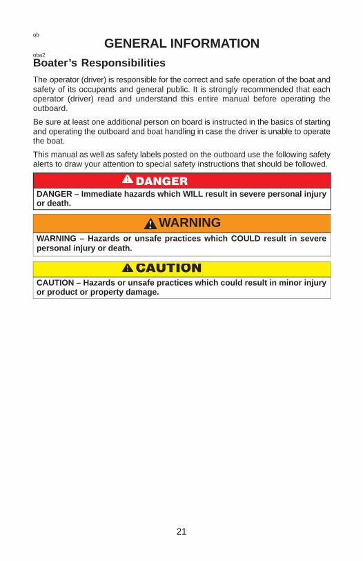
Boater’s ResponsibilitiesThe operator (driver) is responsible for the correct and safe operation of the boat andsafety of its occupants and general public. It is strongly recommended that eachoperator (driver) read and understand this entire manual before operating theoutboard.
Be sure at least one additional person on board is instructed in the basics of startingand operating the outboard and boat handling in case the driver is unable to operatethe boat.
This manual as well as safety labels posted on the outboard use the following safetyalerts to draw your attention to special safety instructions that should be followed.
������
DANGER – Immediate hazards which WILL result in severe personal injuryor death.
WARNINGWARNING – Hazards or unsafe practices which COULD result in severepersonal injury or death.
�����
CAUTION – Hazards or unsafe practices which could result in minor injuryor product or property damage.

22
ob
GENERAL INFORMATIONobb2
Before Operating Your OutboardRead this manual carefully. Learn the difference in handling characteristics betweena jet drive boat and a propeller driven boat including:
• Steering at low speeds - unlike propeller driven boats, the jet drive boat tends tolose steering control as less water is drawn in and expelled. Increase speedslightly to regain steering.
• Maneuverability - the jet drive is highly maneuverable at higher speeds, more so,than propeller driven boats. Use caution when turning to prevent spin-outs.
• In neutral - the impeller continues to rotate. Although the approximate balancingof forward and reverse thrust will minimize boat movement, the boat may tendto creep slowly forward or backward. This is normal for a direct-drive jet-drivenboat. The operator should be aware of this and use caution whenever the engineis running.
If you have any questions, contact your dealer.
Safety and operating information that is practiced along with using good commonsense can help prevent personal injury and product damage.obl9
Recording Serial NumberIt is important to record this number for future reference. The serial number is locatedon the outboard as shown.
a - Serial Numberb - Model Yearc - Model Designationd - Year Manufacturede - Certified Europe Insignia (as Applicable)gob30
20XX
XX
OTXXXXXX
XXXX
a
cb
de
23
ob
GENERAL INFORMATIONgob1
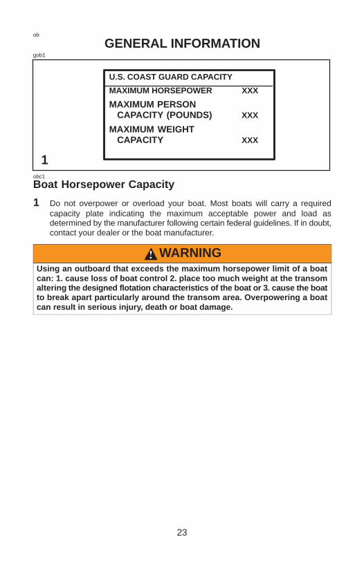
U.S. COAST GUARD CAPACITY
MAXIMUM HORSEPOWER XXX
MAXIMUM PERSON CAPACITY (POUNDS) XXX
MAXIMUM WEIGHT CAPACITY XXX
1obc1
Boat Horsepower Capacity
1 Do not overpower or overload your boat. Most boats will carry a requiredcapacity plate indicating the maximum acceptable power and load asdetermined by the manufacturer following certain federal guidelines. If in doubt,contact your dealer or the boat manufacturer.
WARNINGUsing an outboard that exceeds the maximum horsepower limit of a boatcan: 1. cause loss of boat control 2. place too much weight at the transomaltering the designed flotation characteristics of the boat or 3. cause the boatto break apart particularly around the transom area. Overpowering a boatcan result in serious injury, death or boat damage.

24
ob
GENERAL INFORMATIONgob31
21
a
aobe2
Outboard Remote Control (If Equipped)
1 The remote control connected to your outboard must be equipped with a“start-in-neutral” only protection device. This prevents the engine from startingwhen the shift is actuated in any position other than neutral.
WARNINGAvoid serious injury or death from a sudden unexpected acceleration whenstarting your engine. The design of this outboard requires that the remotecontrol used with it must have a built in “start-in-neutral” only protectiondevice.
obf1
Remote Steering Notice
2 The steering link rod that connects the steering cable to the engine must befastened utilizing self-locking nuts (a). These self- locking nuts must never bereplaced with common nuts (non locking) as they will work loose and vibrate off,freeing the link rod to disengage.
WARNINGDisengagement of a steering link rod can result in the boat taking a full,sudden, sharp turn. This potentially violent action can cause occupants tobe thrown overboard exposing them to serious injury or death.

25
ob
GENERAL INFORMATIONgob8
2 1
obg8
Lanyard Stop Switch
1 The purpose of a lanyard stop switch is to turn off the engine when the operatormoves far enough away from the operator’s position (as in accidental ejectionfrom the operator’s position) to activate the switch. Tiller handle outboards andsome remote control units are equipped with a lanyard stop switch. A lanyardstop switch can be installed as an accessory – generally on the dashboard orside adjacent to the operator’s position.
2 The lanyard is a cord usually between 4 and 5 feet (1220 and 1524 mm) in lengthwhen stretched out with an element on one end made to be inserted into theswitch and a snap on the other end for attaching to the operator. The lanyard iscoiled to make its at-rest condition as short as possible so as to minimize thelikelihood of lanyard entanglement with nearby objects. It is made as long as itis in its stretched condition to minimize the likelihood of accidental activationshould the operator choose to move around in an area close to the normaloperator’s position. If it is desired to have a shorter lanyard, wrap the lanyardaround the operator’s wrist or leg, or tie a knot in the lanyard.
(continued on next page)

26
ob
GENERAL INFORMATIONLanyard Stop Switch (Continued)Read the following Safety Information before proceeding.
Important Safety Information: The purpose of a lanyard stop switch is to stop theengine when the operator moves far enough away from the operator’s position toactivate the switch. This would occur if the operator accidentally falls overboard ormoves within the boat a sufficient distance from the operator’s position. Accidentalejections and falls overboard are more likely to occur in certain types of boats suchas low sided inflatables or bass boats, high-performance boats and light,sensitive-handling fishing boats operated by hand-tiller. Accidental ejections andfalls overboard are also likely to occur as a result of poor operating practices suchas sitting on the back of the seat or gunwale at planing speeds, standing at planingspeeds, sitting on elevated fishing boat decks, operating at planing speeds inshallow or obstacle-infested waters, releasing your grip on a steering wheel or tillerhandle that is pulling in one direction, drinking alcohol or consuming drugs, or daring,high-speed boat maneuvers.
While activation of the lanyard stop switch will stop the engine immediately, a boatwill continue to coast for some distance depending upon the velocity and degree ofany turn at shut-down. However, the boat will not complete a full circle. While the boatis coasting, it can cause injury to anyone in the boat’s path as seriously as the boatwould when under power.
We strongly recommend that other occupants be instructed on proper starting andoperating procedures should they be required to operate the engine in anemergency (e.g. if the operator is accidentally ejected).
WARNINGShould the operator fall out of the boat, the possibility of serious injury ordeath from being run over by the boat can be greatly reduced by stoppingthe engine immediately. Always properly connect both ends of the stopswitch lanyard – to the stop switch and the operator.
(continued on next page)

27
ob
GENERAL INFORMATIONLanyard Stop Switch (Continued)Accidental or unintended activation of the switch during normal operation is also apossibility. This could cause any, or all, of the following potentially hazardoussituations:
1. Occupants could be thrown forward due to unexpected loss of forward motion– a particular concern for passengers in the front of the boat who could beejected over the bow and possibly struck by the hull.
2. Loss of power and directional control in heavy seas, strong current or highwinds.
3. Loss of control when docking.
WARNINGAvoid serious injury or death from deceleration forces resulting fromaccidental or unintended stop switch activation. The boat operator shouldnever leave the operator’s station without first disconnecting the stopswitch lanyard from the operator.
obo1
Stopping The Boat In An EmergencyYour jet powered boat has emergency stopping capability unique to this form ofpropulsion.
In an emergency, putting the remote control handle into reverse and applyingreverse throttle can rapidly slow down your boat and reduce the stopping distance.Keep in mind, however, that such a maneuver may cause occupants in the boat tobe thrown forward or even out of the boat.
WARNINGUsing the emergency stopping capability of your jet drive will slow downyour boat in an emergency. However keep in mind, sudden stopping maycause the occupants in the boat to be thrown forward or even out of the boat.This action may result in serious injury or death.

28
ob
GENERAL INFORMATIONgob3
obh3
Protecting People In The Water
WHILE YOU ARE CRUISING
It is very difficult for a person standing or floating in the water to take quick action toavoid a boat heading in their direction even at slow speed.
Always slow down and exercise extreme caution any time you are boating in an areawhere there might be people in the water.
Avoid shallow water or where any loose material such as sand, shells, seaweed,grass, tree branches, etc. can be sucked in and expelled from the the pump as a highspeed projectile.obp1
WHILE BOAT IS STATIONARY
Stop the engine immediately whenever anyone in the water is near your boat. Thejet drive is always drawing water through the water intake when the engine is running.Stay away from the water intake located under the jet drive and never insert an objectinto the water intake or water outlet nozzle when the engine is running.
WARNINGAvoid injury resulting from contacting the rotating impeller or having yourhair, clothing or loose objects drawn into the water intake and wrappingaround the impeller shaft. Stay away from the water intake and never insertan object into the water intake or water outlet nozzle when the engine isrunning.
29
ob
GENERAL INFORMATIONgob4
obu1
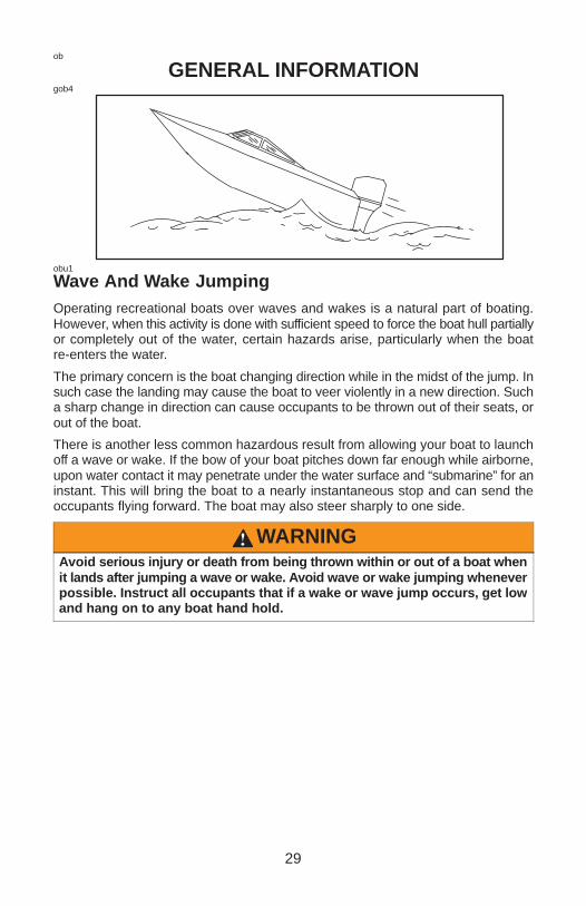
Wave And Wake JumpingOperating recreational boats over waves and wakes is a natural part of boating.However, when this activity is done with sufficient speed to force the boat hull partiallyor completely out of the water, certain hazards arise, particularly when the boatre-enters the water.
The primary concern is the boat changing direction while in the midst of the jump. Insuch case the landing may cause the boat to veer violently in a new direction. Sucha sharp change in direction can cause occupants to be thrown out of their seats, orout of the boat.
There is another less common hazardous result from allowing your boat to launchoff a wave or wake. If the bow of your boat pitches down far enough while airborne,upon water contact it may penetrate under the water surface and “submarine” for aninstant. This will bring the boat to a nearly instantaneous stop and can send theoccupants flying forward. The boat may also steer sharply to one side.
WARNINGAvoid serious injury or death from being thrown within or out of a boat whenit lands after jumping a wave or wake. Avoid wave or wake jumping wheneverpossible. Instruct all occupants that if a wake or wave jump occurs, get lowand hang on to any boat hand hold.

30
ob
GENERAL INFORMATIONgob4
Courtesy of ABYC1obi2
Exhaust Emissions
BE ALERT TO CARBON MONOXIDE POISONING
Carbon monoxide is present in the exhaust fumes of all internal combustion enginesincluding the outboards, stern drives and inboard engines that propel boats, as wellas the generators that power various boat accessories. Carbon monoxide is adeadly gas that is odorless, colorless and tasteless.
Early symptoms of carbon monoxide poisoning which should not be confused withseasickness or intoxication, include headache, dizziness, drowsiness, and nausea.
WARNINGAvoid the combination of a running engine and poor ventilation. Prolongedexposure to carbon monoxide in sufficient concentration can lead tounconsciousness, brain damage, or death.
GOOD VENTILATION
Ventilate passenger area, open side curtains, or forward hatches to remove fumes.
1 Example of desired air flow through the boat.
31
ob
GENERAL INFORMATIONgob39
a
c
b
d
Courtesy of ABYC2obi3
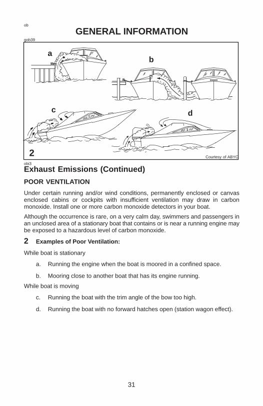
Exhaust Emissions (Continued)
POOR VENTILATION
Under certain running and/or wind conditions, permanently enclosed or canvasenclosed cabins or cockpits with insufficient ventilation may draw in carbonmonoxide. Install one or more carbon monoxide detectors in your boat.
Although the occurrence is rare, on a very calm day, swimmers and passengers inan unclosed area of a stationary boat that contains or is near a running engine maybe exposed to a hazardous level of carbon monoxide.
2 Examples of Poor Ventilation:
While boat is stationary
a. Running the engine when the boat is moored in a confined space.
b. Mooring close to another boat that has its engine running.
While boat is moving
c. Running the boat with the trim angle of the bow too high.
d. Running the boat with no forward hatches open (station wagon effect).
32
ob
GENERAL INFORMATIONobj2
Selecting Accessories For Your OutboardGenuine Mercury Precision or Quicksilver Accessories have been specificallydesigned and tested for your outboard. These accessories are available fromMercury Marine dealers.
Some accessories not manufactured or sold by Mercury Marine are not designed tobe safely used with your outboard or outboard operating system. Acquire and readthe installation, operation, and maintenance manuals for all your selectedaccessories.
WARNINGCheck with your dealer before installation of accessories. The misuse ofacceptable accessories or the use of unacceptable accessories can resultin serious injury, death, or product failure.
obk2
Safe Boating SuggestionsIn order to safely enjoy the waterways, familiarize yourself with local and othergovernment boating regulations and restrictions, and consider the followingsuggestions.
Use flotation devices. Have an approved personal flotation device of suitable sizefor each person aboard (it is the law) and have it readily accessible.
Do not overload your boat. Most boats are rated and certified for maximum load(weight) capacities (refer to your boat capacity plate). If in doubt, contact your dealeror the boats manufacturer.
Perform safety checks and required maintenance. Follow a regular schedule andensure that all repairs are properly made.
(continued on next page)
33
ob
GENERAL INFORMATIONSafe Boating Suggestions (Continued)Know and obey all nautical rules and laws of the waterways. Boat operatorsshould complete a boating safety course. Courses are offered in the U.S.A. by (1)The U.S. Coast Guard Auxiliary, (2) The Power Squadron, (3) The Red Cross and(4) your state boating law enforcement agency. Inquiries may be made to the BoatingHot-line, 1-800-368-5647 or the Boat U.S. Foundation information number1-800-336-BOAT.
Make sure everyone in the boat is properly seated. Don’t allow anyone to sit orride on any part of the boat that was not intended for such use. This includes backsof seats, gunwales, transom, bow, decks, raised fishing seats, any rotating fishingseat; anywhere that sudden unexpected acceleration, sudden stopping,unexpected loss of boat control or sudden boat movement could cause a person tobe thrown overboard or into the boat.
Never be under the influence of alcohol or drugs while boating (it is the law).They impair your judgment and greatly reduce your ability to react quickly.
Prepare other boat operators. Instruct at least one person on board in the basicsof starting and operating the jet drive and boat handling in case the driver becomesdisabled or falls overboard.
Passenger boarding. Stop the engine whenever passengers are boarding,unloading or are near the back (stern) of the boat. Just shifting the outboard intoneutral is not sufficient.
Be alert. The operator of the boat is responsible by law to “maintain a proper lookoutby sight (and hearing).” The operator must have an unobstructed view particularlyto the front. No passengers, load, or fishing seats should block the operators viewwhen operating the boat above idle speed.
Avoid shallow water conditions. Never operate your jet drive in very shallow wateror where there is a noticeable amount of floating debris or weeds. Always be in atleast 2 to 3 feet of water. Any loose material such as sand, shells, seaweed, grass.tree branches or etc. can be sucked up by the pump and may not only block the waterflow and cause lost of steering control but can be expelled from the rear of the pumpas a high-speed projectile.
(continued on next page)

34
ob
GENERAL INFORMATIONSafe Boating Suggestions (Continued)Watch for boat creeping in neutral. When the jet drive is in neutral, the driveimpeller continues to rotate. Although the approximate balancing of forward andreverse thrust will minimize boat movement, the boat may tend to creep slowlyforward or backward. This is normal for a direct-drive jet-driven boat. The operatorshould be aware of this and use caution whenever the engine is running.
Never drive your boat directly behind a water skier in case the skier falls. Asan example, your boat traveling at 25 miles per hour (40 km/hr) in 5 seconds willovertake a fallen skier who was 200 feet (61m) in front of you.
Watch fallen skiers. When using your boat for water skiing or similar activities,always keep a fallen or down skier on the operator’s side of the boat while returningto attend the skier. The operator should always have the down skier in sight andnever back up to the skier or anyone in the water.
Report accidents. Boat operators are required by law to file a Boating AccidentReport with their state boating law enforcement agency when their boat is involvedin certain boating accidents. A boating accident must be reported if (1) there is lossof life or probable loss of life, (2) there is personal injury requiring medical treatmentbeyond first aid, (3) there is damage to boats or other property where the damagevalue exceeds $500.00 or (4) there is complete loss of the boat. Seek furtherassistance from local law enforcement.

35
ob
GENERAL INFORMATIONobm13
Specifications
Models 20Jet Power 20
Engine Horsepower 25
Full Throttle RPM Range 5000-6000 RPM
Idle Speed in Forward Gear 750 ± 50 RPM
Number of Cylinders 2
Piston Displacement 24.4 cu. in. (400cc)
Cylinder Bore 2.560 in. (65mm)
Piston Stroke 2.360 in. (60mm)
Recommended Spark Plug NGK BP8H-N-10*
Spark Plug Gap .040 in. (1.0mm)
Recommended Gasoline Refer to Fuel Section
Recommended Oil Refer to Fuel Section
Battery Rating 465 Marine Cranking Amps (MCA)or 350 Cold Cranking Amps (CCA)
*Use NGK BPZ8H-N-10 spark plug where radio frequency interference (RFI)suppression is required.

36
oc
INSTALLATIONgoc18
1 2
a c
b
ocj1
Installing Outboard On The TransomNOTE: Determine the recommended mounting height of your outboard by followinginstructions in the outboard jet installation supplement(provided with the outboard).
1 Place outboard on center line of transom. Tighten transom clamp handles.
2 To prevent loss of outboard overboard, fasten outboard by drilling two 5/16 in.(7.9 mm) holes through the transom using transom clamp holes as a template.Fasten with two bolts (a), flat washers (b) and locknuts (c). Use a marinewaterproofing sealer in holes and around bolts to make the installation watertight.

37
oc
INSTALLATIONgoc19
3occ1
Fastening Security Line
3 The primary purpose for installing a security line is to prevent loss of theoutboard if the outboard becomes detached from the boat transom.
An effective security line should be of a working strength of at least five times theweight of the outboard.
The security line should be attached between the boat and outboard following oneof these steps.
Step 1. The length of the security line should be short enough and affixed in a mannerto prevent the outboard from rising up and disengaging off the boat transom.
Step 2. The length of the security line should be long enough and affixed in a mannerto permit a detached outboard to submerge completely behind the boat and stoprunning but not too short that could allow the outboard to continue running and propelitself back into the boat.
WARNINGIf the length of security line being used is long enough to allow the outboardto disengage off the boat transom but is too short to not allow the outboardto submerge behind the boat and stop running, the outboard could continuerunning and propel itself back into the boat with the propeller rotating underpower. This exposes the occupants to serious injury or death.

38
oc
INSTALLATIONgoc20
4-6
ock1
Battery Installation – Electric Start Models
MOUNTING BATTERY
4 Follow battery manufacturer’s instructions carefully. Mount battery in the boatso it is secured against movement, preferably in a battery box. Make surebattery is equipped with a nonconductive shield to prevent accidental shortingof battery terminals.
ocg1
Battery Connections
CONNECTING OUTBOARD BATTERY CABLES
5 First, connect the red battery cable to the (+) positive battery terminal and thenconnect the black battery cable to the (–) negative battery terminal.
DISCONNECTING OUTBOARD BATTERY CABLES
6 First, disconnect the black battery cable from the (–) negative terminal and thendisconnect the red battery cable from the (+) positive terminal.

39
od
TRANSPORTINGgod12
1oda5
Carrying Your Outboard
1 Your outboard has a carrying handle located in front and a rear hand grip in thebottom cowl.
Trailering Your BoatYour boat should be trailered with the outboard tilted down (normal operatingposition).
IMPORTANT: The tilt lock and shallow water drive feature (tiller handle models)on the outboard are not intended to support the outboard in the tilted positionwhen trailering your boat.
If additional ground clearance is required, the outboard should be tilted up using anoutboard support bar. Additional clearance may be needed for railroad crossings,driveways, and trailer bouncing.

40
od
TRANSPORTINGgod19
2 3-41
F
a
b
odb2
Transporting Your Outboard When Removed From Boat
1 With the outboard still in the water, disconnect the fuel line from the outboard andrun engine until it stops, draining carburetor. Remove outboard from the boatand hold upright until all cooling water is drained out. Lay the outboard downhorizontally on it’s (tiller handle) side. Place a protective pad under the outboard.
odh1
Transporting Portable Fuel Tanks
MANUAL VENTING TYPE FUEL TANK
2 Close fuel tank air vent when transporting tank. This will prevent escape of fuelor vapors from tank.
AUTO-VENTING TYPE FUEL TANK
3 Disconnect the remote fuel line from tank. This will close the air vent and preventescape of fuel or vapors from tank.
4 Install tether cap (a) over the fuel line connector stem (b). This will protect theconnector stem from being accidently pushed-in, thus, allowing fuel or vapor toescape.
WARNINGAvoid serious injury or death from a gasoline fire or explosion. Followportable fuel tank transporting instructions. Transport the fuel tank in a wellventilated area away from open flame or sparks.

41
oe
FUEL & OILoeb6
Gasoline Recommendations
UNITED STATES AND CANADA
Use a major brand of automotive unleaded gasoline with a minimum posted octanerating of 87. Mid-grade automotive gasolines that contain fuel injector cleaner arepreferred for added internal engine cleanliness. Leaded gasoline is notrecommended.
INTERNATIONAL
Use a major brand of automotive unleaded gasoline with a minimum posted octanerating of 90RON. Automotive gasolines that contain fuel injector cleaner arepreferred for added internal engine cleanliness. Leaded gasoline is acceptable inareas where unleaded gasoline is not available.
ALCOHOL IN GASOLINE
We do not recommend the use of gasoline which contains alcohol because of thepossible adverse effect the alcohol may have on the fuel system. In general, if onlygasoline containing alcohol is available, it must not contain more than 10% ethanolor 5% methanol, and the addition of a Water Separating Fuel Filter is recommended.
If gasoline containing alcohol is used or if you suspect the presence of alcohol in yourgasoline, increase your inspection of the fuel system, visually checking for fuel leaksor abnormalities.
Gasoline containing alcohol may cause the following problems to your outboard andfuel system:
• Corrosion of metal parts.
• Deterioration of elastomers and plastic parts.
• Wear and damage of internal engine parts.
• Starting and operating difficulties.
• Vapor lock or fuel starvation.
Some of these adverse effects are due to the tendency of gasoline containingalcohol to absorb moisture from the air, resulting in a phase of water and alcoholwhich separates from the gasoline in the fuel tank.
The adverse effects of alcohol are more severe with methanol and are worse withincreasing content of alcohol.

42
oe
FUEL & OILoec13
Oil RecommendationMercury or Quicksilver Premium TC-W3 2-cycle oil is recommended for your engine.For added protection and lubrication, Mercury or Quicksilver Premium Plus TC-W32-cycle oil is recommended. If Mercury or Quicksilver outboard oil is not available,substitute another brand of 2-cycle outboard oil that is NMMA Certified TC-W3.Severe engine damage may result from use of an inferior oil.oeg8
Mixing Fuel And OilUse a 25:1 (4%) gasoline/oil mixture in the first tank of fuel.
After the break-in fuel mixture is used up, use a 50:1 (2%) gasoline/oil mixture. Followthe table below for mixing ratios.oeh1
GASOLINE/OIL MIXING RATIO CHART
Gas/OilRatio
1 GallonGas
(3.8 Liters)
3 GallonsGas
(11.5 Liters)
6 GallonsGas
(23 Liters)
25:1(4%)
5 fl. oz.(148 ml)Oil
16 fl. oz.(473 ml) Oil
32 fl. oz.(946 ml) Oil
50:1(2%)
3 fl. oz.(89 ml) Oil
8 fl. oz.(237 ml) Oil
16 fl. oz.(473 ml) Oil
43
oe
FUEL & OILoee6
Filling Fuel Tank
WARNINGAvoid serious injury or death from a gasoline fire or explosion. Always stopthe engine and DO NOT smoke or allow open flames or sparks in the areawhile filling fuel tanks.
Fill fuel tanks outdoors away from heat, sparks, and open flames.
Always stop engine before refilling tanks.
Do not completely fill the fuel tanks. Leave approximately 10% of the tank volumeunfilled. Fuel will expand in volume as its temperature rises and can leak underpressure if the tank is completely filled.
FILLING FUEL TANKS PERMANENTLY INSTALLED
Slowly pour the correct amount of oil along with the gasoline as the tank is being filled.
FILLING PORTABLE FUEL TANKS
Remove portable fuel tanks from boat to refill them.
Pour the full amount of oil along with approximately one gallon of gasoline into thefuel tank. Mix thoroughly, then pour the remainder of gasoline into the tank.
PORTABLE FUEL TANK PLACEMENT IN THE BOAT
Place the fuel tank in the boat so that the tank vent will stay higher than the fuel levelin the tank under normal boat operating conditions.

44
og
FEATURES & CONTROLSgog79
1 2 3ogd8
Tiller Handle Models
1 Tiller handle – Handle can be tilted 100° for convenient handling duringtransportation and storage.
2 Starter Rope – Pulling the starter rope cranks the engine over for starting.
3 Primer/Idle Speed Knob – Pulling the knob out supplies a small amount of fuelto the engine for cold starting. Rotate knob to adjust idle speed after enginewarms up.
45
og
FEATURES & CONTROLSgog80
54 6ogd12
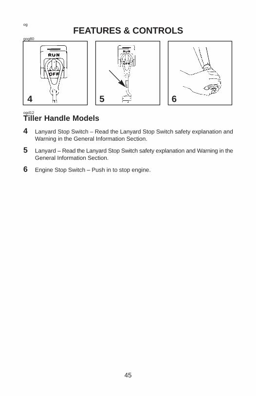
Tiller Handle Models
4 Lanyard Stop Switch – Read the Lanyard Stop Switch safety explanation andWarning in the General Information Section.
5 Lanyard – Read the Lanyard Stop Switch safety explanation and Warning in theGeneral Information Section.
6 Engine Stop Switch – Push in to stop engine.
46
og
FEATURES & CONTROLSgog81
7 8
RF
ab
ogd10
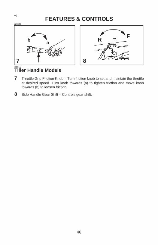
Tiller Handle Models
7 Throttle Grip Friction Knob – Turn friction knob to set and maintain the throttleat desired speed. Turn knob towards (a) to tighten friction and move knobtowards (b) to loosen friction.
8 Side Handle Gear Shift – Controls gear shift.
47
og
FEATURES & CONTROLSgog28
11109
a b
ogd11
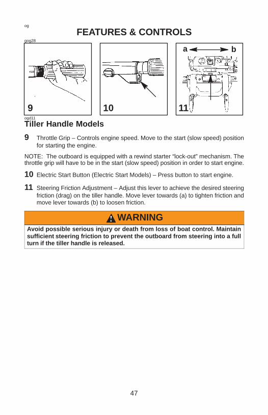
Tiller Handle Models
9 Throttle Grip – Controls engine speed. Move to the start (slow speed) positionfor starting the engine.
NOTE: The outboard is equipped with a rewind starter “lock-out” mechanism. Thethrottle grip will have to be in the start (slow speed) position in order to start engine.
10 Electric Start Button (Electric Start Models) – Press button to start engine.
11 Steering Friction Adjustment – Adjust this lever to achieve the desired steeringfriction (drag) on the tiller handle. Move lever towards (a) to tighten friction andmove lever towards (b) to loosen friction.
WARNINGAvoid possible serious injury or death from loss of boat control. Maintainsufficient steering friction to prevent the outboard from steering into a fullturn if the tiller handle is released.

48
og
FEATURES & CONTROLSgog82
3
41-2ogf4
Tilting Outboard To Full Up Position
1 Stop the engine. Shift the outboard into forward gear position.
2 Take hold of the top cowl grip and raise outboard to the full up position.
3 Move the tilt lock to the lock position.
Lowering Outboard Down To Run Position
4 Lift outboard and release tilt lock lever. Lower outboard.

49
og
FEATURES & CONTROLSgog83
1–2 3
a
c
b
ogm1
Shallow Water Operation – Tiller Handle ModelsTiller handle model outboards are equipped with a shallow water tilt feature thatallows you to tilt the outboard to a higher tilt angle to prevent hitting bottom.
ENGAGING SHALLOW WATER DRIVE
1 Reduce engine speed to idle. Shift the outboard into forward gear position.
2 Push down the shallow water drive lever (a). Tilt outboard up to the shallowwater drive position. Be sure the cooling water intake (c) is submerged.
IMPORTANT: While in shallow water drive position, do not operate theoutboard in reverse. Operate the outboard at slow speed and keep the coolingwater intake submerged.
3 To release down to run position, lift up the shallow water drive lever (b). Tilt upthe outboard to disengage the shallow water drive lock and lower it down.

50
og
FEATURES & CONTROLSgog84
a
ogg3
Setting The Operating Angle Of Your OutboardThe vertical operating angle of your outboard is adjusted by changing the positionof the tilt pin (a) in the five adjustment holes provided. Proper adjustment allows theboat to run stable, achieve optimum performance.
The tilt pin should be adjusted so the outboard is positioned to run perpendicular tothe water when the boat is running at full speed. This allows the boat to be drivenparallel to the water.
Arrange passengers and load in the boat so the weight is distributed evenly.
51
of
OPERATIONofa4
Pre-Starting Check List� Operator knows safe navigation, boating, and operating procedures.
� An approved personal flotation device of suitable size for each person aboardand readily accessible (it is the law).
� A ring type life buoy or buoyant cushion designed to be thrown to a person in thewater.
� Know your boats maximum load capacity. Look at the boat capacity plate.
� Fuel supply OK.
� Oil supply (oil injection) OK.
� Make sure the boat drain plug is installed.
� Arrange passengers and load in the boat so the weight is distributed evenly andeveryone is seated in a proper seat.
� Tell someone where you are going and when you expect to return.
� It is illegal to operate a boat while under the influence of alcohol or drugs.
� Know the waters and area you will be boating; tides, currents, sand bars, rocks,and other hazards.
� Make inspection checks listed in the Inspection and Maintenance Schedule.Refer to Maintenance Section.
� Check steering for free operation.
� Check for debris around the rudder and reverse gate which may jam or hinderoperation.
� Before launching, examine the jet drive water intake for obstructions which mayprevent pumping of water.
� Make sure the drive shaft bearing on the jet drive is lubricated.
52
of
OPERATIONgof86
ac
b
onm1
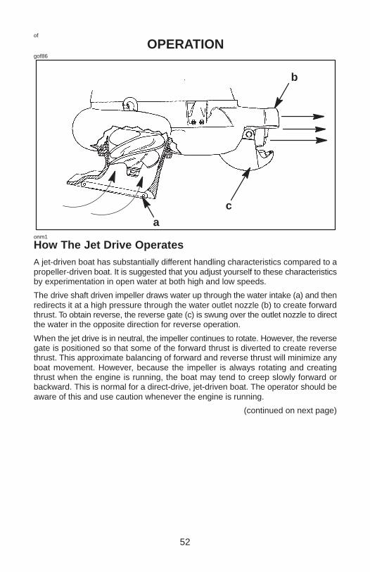
How The Jet Drive OperatesA jet-driven boat has substantially different handling characteristics compared to apropeller-driven boat. It is suggested that you adjust yourself to these characteristicsby experimentation in open water at both high and low speeds.
The drive shaft driven impeller draws water up through the water intake (a) and thenredirects it at a high pressure through the water outlet nozzle (b) to create forwardthrust. To obtain reverse, the reverse gate (c) is swung over the outlet nozzle to directthe water in the opposite direction for reverse operation.
When the jet drive is in neutral, the impeller continues to rotate. However, the reversegate is positioned so that some of the forward thrust is diverted to create reversethrust. This approximate balancing of forward and reverse thrust will minimize anyboat movement. However, because the impeller is always rotating and creatingthrust when the engine is running, the boat may tend to creep slowly forward orbackward. This is normal for a direct-drive, jet-driven boat. The operator should beaware of this and use caution whenever the engine is running.
(continued on next page)

53
of
OPERATIONHow The Jet Drive Operates (Continued)The jet drive is always drawing water into the housing when the engine is running.DO NOT operate the jet drive with the grate removed from the water intake. Keepyour hands, feet, hair, loose clothing, life jackets, etc. away from the water intake.Never insert an object into the water intake or water outlet nozzle when the engineis running.
WARNINGAvoid injury resulting from contacting the rotating impeller or having yourhair, clothing, or loose objects drawn into the water intake and wrappingaround the impeller. Stay away from the water intake and never insert anobject into the water intake or water outlet nozzle when the engine is running.
ofz1
Stopping The Boat In An EmergencyYour jet powered boat has emergency stopping capability unique to this form ofpropulsion.
In an emergency, shifting the jet drive into reverse and applying reverse throttle canrapidly slow down your boat and reduce the stopping distance. Keep in mind,however, that such a maneuver may cause occupants in the boat to be thrownforward or even out of the boat.
WARNINGUsing the emergency stopping capability of your jet drive will slow downyour boat in an emergency. However, keep in mind, sudden stopping maycause the occupants in the boat to be thrown forward or even out of the boat.This action may result in serious injury or death.
54
of
OPERATIONonl1
Steering Your BoatThe jet drive is dependent on water jet thrust for steering the boat. The jet drive hasa steerable outlet nozzle that directs this water jet thrust to the right or left. If the waterjet thrust should ever stop, (water blockage, the engine stops, or, etc.) will cause theboat to slow to a stop. However, while slowing there will be a reduced ability to steerthe boat.
While steering your outboard, you will find quick response to the helm, but due to therelatively flat-bottom hulls and lack of a gear case in the water, your boat will tend toskid on the turns. You must start your turns early and use sufficient power to maintainsteering control.
WARNINGAvoid serious injury or death. Do not attempt to steer your boat into a tightturn; at too high a speed, your boat could “spin out” or even roll over,resulting in occupants being thrown within the boat or out of the boat.
WARNINGAvoid injury, death or property damage resulting from collision due to lossof directional control. Directional control is derived from the water jet thrust.Thus, caution should be exercised when maneuvering at higher speeds inareas where debris (weeds, logs, gravel, etc.) could be picked up into the jetdrive. This can cut off or reduce the water jet thrust, thereby directly affectingboat directional control. Boat directional control can also be substantiallyreduced or lost altogether by a sudden loss of power such as running out ofgas, quickly backing off throttle, turning off ignition switch, or activatinglanyard stop switch. Remember your ability to take evasive action isdependent on sufficient water jet thrust to control your boat.

55
of
OPERATIONonk1
Operating In Shallow WaterThe life of the impeller and water intake can be greatly increased by avoiding theintake of sand and gravel. The intake suction, acting on the bottom, will act like adredge when the water intake comes within 2 to 3 inches of the bottom. It is betterto stop the engine and drift up to shore when landing, and to shove off with an oarwhen leaving. You can idle through areas of water less than 1-foot deep, but thereshould be more than 1-foot of water under the boat when increasing speed to reachfull plane.
Once the boat is on plane, the boat speed will prevent sucking in gravel and otherdebris off the bottom. The sucking is still acting, but the water intake passes over thebottom too quickly to allow debris to be lifted into the water intake.
While boating through shallow water areas, decide a course of travel that avoidssharp rocks and other underwater obstacles that could damage the boat. Runningyour boat through these areas on full plane may be helpful because the boat will beriding higher in the water. If the boat gets stuck on the bottom, immediately stop theengine and move the boat to deeper water.onj1
Water Intake BlockageIt is possible to lose power caused by suction holding flat stones. weeds, leaves,plastic, paper, or other debris against the water intake and restricting water flow. Ifyou shut off the engine and wait a few seconds, the debris may fall off and full powerwill be restored. If, however, the debris trapped in the water intake grate, the enginewill have to be shut off and the blockage will have to be pried out.
WARNINGAvoid injury resulting from contacting the rotating impeller. Always shut offthe engine before attempting to remove a blockage from the water intake.
56
of
OPERATIONona1
Clearing A Jammed ImpellerIt is possible, for a stone or other debris inside the jet housing to lodge between theimpeller and wall, especially after the engine has been stopped. This will lock thedrive shaft and will prevent the engine from being able to crank over for starting. Inthis case follow these steps for freeing the jam.
Turn the ignition key or lanyard stop switch to the OFF position and remove all thespark plug leads to prevent the engine from accidently starting. Remove the flywheelor rewind cover and rotate the engine flywheel counterclockwise. If this doesn’t freethe jammed impeller, it will be necessary to remove the six screws and water intakehousing.
WARNINGIf the flywheel is rotated to free a jammed impeller, there is the possibility thatthe engine will crank over and start. To prevent this type of accidental enginestarting and possible serious injury, always turn the ignition key or lanyardstop switch to the OFF position and remove all spark plug leads from thespark plugs.
oni1
Mooring Your BoatWhen your boat is pulled onto a beach or tied to a dock where the up and down waveaction may cause the water intake housing to dig into sand or other debris, be sureto tilt the jet drive out of water. Failure to do this may cause the water intake housingto fill with sand or other debris and could prevent the outboard from cranking over forstarting.onf3
Operating In Freezing TemperaturesIf there is a chance of ice forming on the water, the jet drive should be removed anddrained completely of water. If ice should form at the water level inside the outboarddrive shaft housing, it will block water flow to the engine causing possible damage.Do not start the engine until the ice is clear.

57
of
OPERATIONofy7
Operating At High ElevationsOperating your outboard at an elevation higher than 2500 ft. (750 m) above sea levelmay require a carburetor jet change. Consult your dealer. This will reduce the normalperformance loss experienced as a result of reduced oxygen in the air causing anoverly rich fuel mixture.
IMPORTANT: To prevent serious damage to the engine caused by a lean fuelmixture, DO NOT operate your outboard (if the carburetor jets were changedfor high elevation) at a lower elevation unless the jets are changed again tocorrespond to the new elevation.one2
Operating In Salt Water Or Polluted WaterIf you keep your boat moored in the water, always tilt the outboard so the water intakeis completely out of water (except in freezing temperature) when not in use.
Wash down the outboard exterior and flush out the exhaust outlet of the jet drive withfresh water after each use. Each month, spray Quicksilver or Mercury PrecisionCorrosion Guard on external metal surfaces.
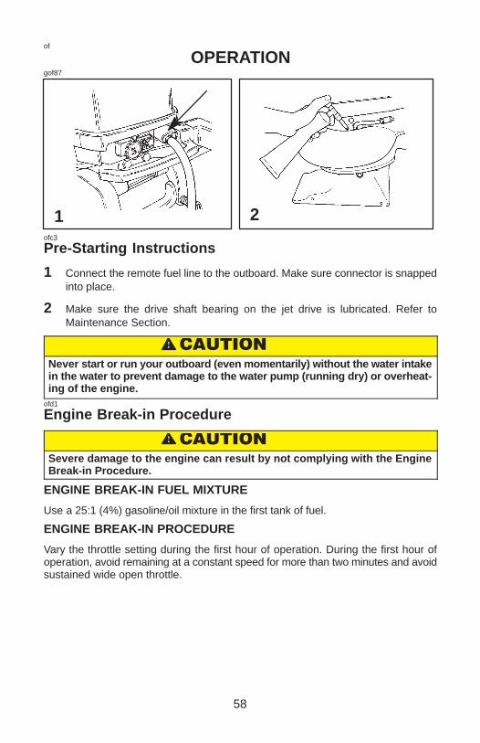
58
of
OPERATIONgof87
21ofc3
Pre-Starting Instructions
1 Connect the remote fuel line to the outboard. Make sure connector is snappedinto place.
2 Make sure the drive shaft bearing on the jet drive is lubricated. Refer toMaintenance Section.
�����
Never start or run your outboard (even momentarily) without the water intakein the water to prevent damage to the water pump (running dry) or overheat-ing of the engine.
ofd1
Engine Break-in Procedure
�����
Severe damage to the engine can result by not complying with the EngineBreak-in Procedure.
ENGINE BREAK-IN FUEL MIXTURE
Use a 25:1 (4%) gasoline/oil mixture in the first tank of fuel.
ENGINE BREAK-IN PROCEDURE
Vary the throttle setting during the first hour of operation. During the first hour ofoperation, avoid remaining at a constant speed for more than two minutes and avoidsustained wide open throttle.
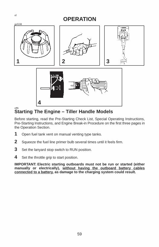
59
of
OPERATIONgof108
1 2 3
4off6
Starting The Engine – Tiller Handle ModelsBefore starting, read the Pre-Starting Check List, Special Operating Instructions,Pre-Starting Instructions, and Engine Break-in Procedure on the first three pages inthe Operation Section.
1 Open fuel tank vent on manual venting type tanks.
2 Squeeze the fuel line primer bulb several times until it feels firm.
3 Set the lanyard stop switch to RUN position.
4 Set the throttle grip to start position.
IMPORTANT: Electric starting outboards must not be run or started (eithermanually or electrically), without having the outboard battery cablesconnected to a battery, as damage to the charging system could result.

60
of
OPERATIONgof89
98
6 75
off1
Starting The Engine – Tiller Handle Models
5 Side Handle Gear Shift Models – Set the gear shift to NEUTRAL position.
6 Turn Primer/idle speed knob full clockwise (direction of arrow) to increaseengine idle speed for starting.
7 When engine is cold, pull out and push in the primer/idle speed knob one to threetimes to prime the engine. Leave the knob in the pulled-out position whenstarting.
8 Manual Starting Models – Pull the starter rope slowly until you feel the starterengage, then pull rapidly to crank the engine. Allow rope to return slowly. Repeatuntil engine starts.
9 Electric Starting Models – Push starter button and crank the engine. Releasebutton when engine starts. Do not operate starter motor continuously for longerthan ten seconds at a time. If engine fails to start, wait 30 seconds and try again.
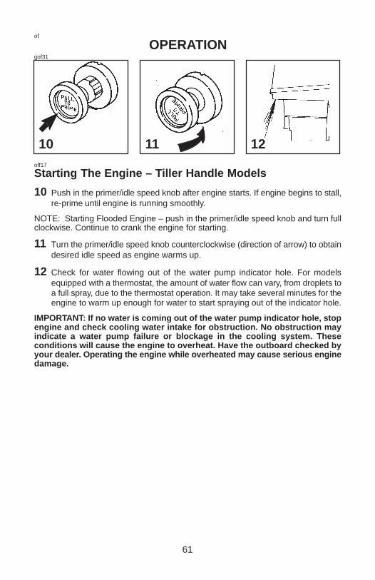
61
of
OPERATIONgof31
10 11 12off17
Starting The Engine – Tiller Handle Models
10 Push in the primer/idle speed knob after engine starts. If engine begins to stall,re-prime until engine is running smoothly.
NOTE: Starting Flooded Engine – push in the primer/idle speed knob and turn fullclockwise. Continue to crank the engine for starting.
11 Turn the primer/idle speed knob counterclockwise (direction of arrow) to obtaindesired idle speed as engine warms up.
12 Check for water flowing out of the water pump indicator hole. For modelsequipped with a thermostat, the amount of water flow can vary, from droplets toa full spray, due to the thermostat operation. It may take several minutes for theengine to warm up enough for water to start spraying out of the indicator hole.
IMPORTANT: If no water is coming out of the water pump indicator hole, stopengine and check cooling water intake for obstruction. No obstruction mayindicate a water pump failure or blockage in the cooling system. Theseconditions will cause the engine to overheat. Have the outboard checked byyour dealer. Operating the engine while overheated may cause serious enginedamage.

62
of
OPERATIONgof90
1
4
RF
2
ofj6
Gear Shifting
1 Your outboard has three gear shift positions to provide operation: Forward (F),Neutral (out of gear), and Reverse (R)
NOTE: In neutral, the impeller continues to rotate. Although the approximatebalancing of forward and reverse thrust will minimize boat movement, the boat maytend to creep slowly forward or backward. This is normal for a direct-drive jet-drivenboat. The operator should be aware of this and use caution whenever the engine isrunning.
2 Align throttle grip pointer with slow speed shift position before shifting outboardinto gear.
3 After shifting outboard into gear, advance the throttle to increase speed.ofn1
Stopping The Engine
4 Reduce engine speed and shift outboard to neutral position. Push in the enginestop button or move the lanyard stop switch to the OFF position.
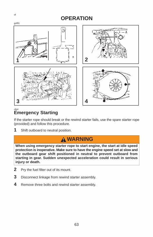
63
of
OPERATIONgof91
2
4
1
3ofp4
Emergency StartingIf the starter rope should break or the rewind starter fails, use the spare starter rope(provided) and follow this procedure.
1 Shift outboard to neutral position.
WARNINGWhen using emergency starter rope to start engine, the start at idle speedprotection is inoperative. Make sure to have the engine speed set at slow andthe outboard gear shift positioned in neutral to prevent outboard fromstarting in gear. Sudden unexpected acceleration could result in seriousinjury or death.
2 Pry the fuel filter out of its mount.
3 Disconnect linkage from rewind starter assembly.
4 Remove three bolts and rewind starter assembly.
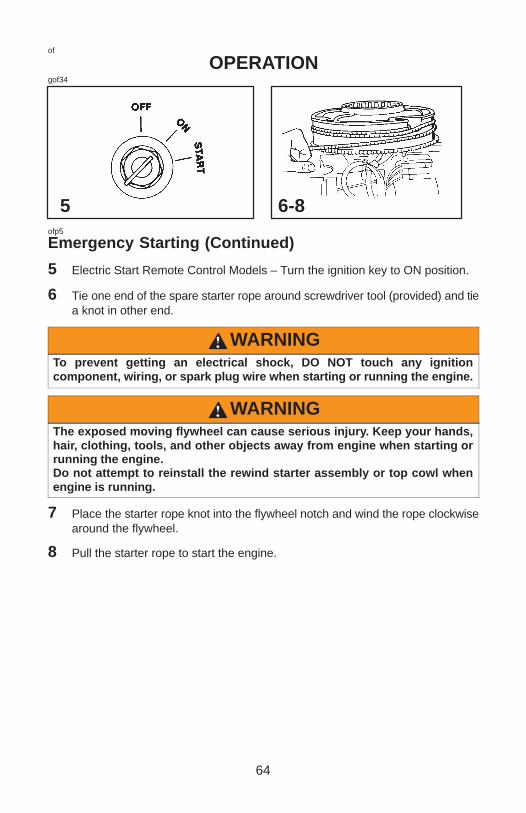
64
of
OPERATIONgof34
6-85ofp5
Emergency Starting (Continued)
5 Electric Start Remote Control Models – Turn the ignition key to ON position.
6 Tie one end of the spare starter rope around screwdriver tool (provided) and tiea knot in other end.
WARNINGTo prevent getting an electrical shock, DO NOT touch any ignitioncomponent, wiring, or spark plug wire when starting or running the engine.
WARNINGThe exposed moving flywheel can cause serious injury. Keep your hands,hair, clothing, tools, and other objects away from engine when starting orrunning the engine.Do not attempt to reinstall the rewind starter assembly or top cowl whenengine is running.
7 Place the starter rope knot into the flywheel notch and wind the rope clockwisearound the flywheel.
8 Pull the starter rope to start the engine.

65
oh
MAINTENANCEoha4
Outboard CareTo keep your outboard in the best operating condition, it is important that youroutboard receive the periodic inspections and maintenance listed in the Inspectionand Maintenance Schedule. We urge you to keep it maintained properly to ensurethe safety of you and your passengers and retain its dependability.
WARNINGNeglected inspection and maintenance service of your outboard orattempting to perform maintenance or repair on your outboard if you are notfamiliar with the correct service and safety procedures could cause personalinjury, death, or product failure.
Record maintenance performed in Maintenance Log at the back of this book. Saveall maintenance work orders and receipts.
Selecting Replacement Parts For Your OutboardWe recommend using original Mercury Precision or Quicksilver replacement partsand Genuine Lubricants.
WARNINGUsing a replacement part that is inferior to the original part could result inpersonal injury, death, or product failure.
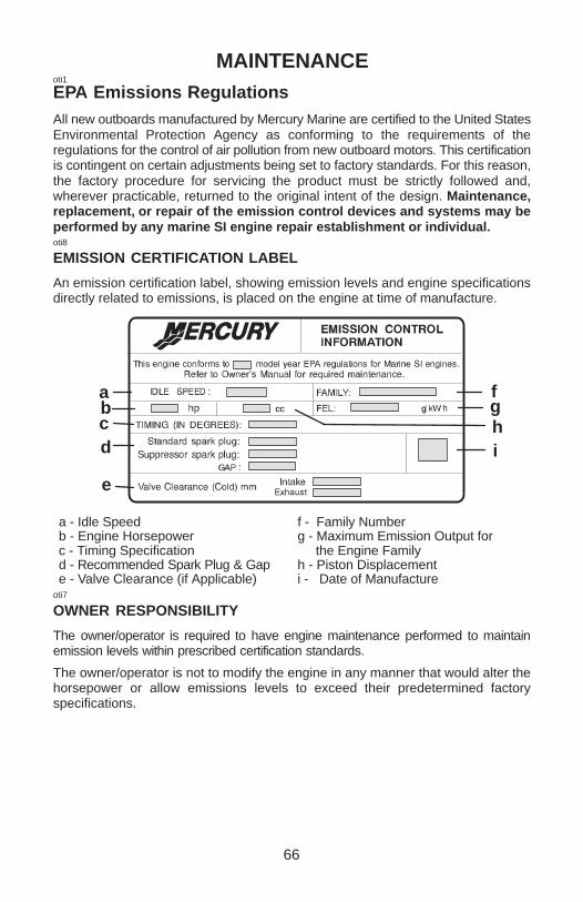
66
MAINTENANCEoti1
EPA Emissions RegulationsAll new outboards manufactured by Mercury Marine are certified to the United StatesEnvironmental Protection Agency as conforming to the requirements of theregulations for the control of air pollution from new outboard motors. This certificationis contingent on certain adjustments being set to factory standards. For this reason,the factory procedure for servicing the product must be strictly followed and,wherever practicable, returned to the original intent of the design. Maintenance,replacement, or repair of the emission control devices and systems may beperformed by any marine SI engine repair establishment or individual.oti8
EMISSION CERTIFICATION LABEL
An emission certification label, showing emission levels and engine specificationsdirectly related to emissions, is placed on the engine at time of manufacture.
a
cd
b
e
f
hi
g
a - Idle Speed b - Engine Horsepowerc - Timing Specificationd - Recommended Spark Plug & Gape - Valve Clearance (if Applicable)
f - Family Number g - Maximum Emission Output for the Engine Family h - Piston Displacementi - Date of Manufacture
oti7
OWNER RESPONSIBILITY
The owner/operator is required to have engine maintenance performed to maintainemission levels within prescribed certification standards.
The owner/operator is not to modify the engine in any manner that would alter thehorsepower or allow emissions levels to exceed their predetermined factoryspecifications.

67
oh
MAINTENANCEohd34
Inspection And Maintenance Schedule
BEFORE EACH USE
1. Check that lanyard stop switch stops the engine.
2. Visually inspect the fuel system for deterioration or leaks.
3. Check outboard for tightness on transom.
4. Check steering system for binding or loose components.
5. Remote Control models – Visually check steering link rod fasteners for propertightness.
6. Make sure the drive shaft bearing on the jet drive is lubricated. (page 73)
AFTER EACH USE AND AFTER EVERY 10 HOURS OF OPERATION
1. Lubricate the drive shaft bearing on the jet drive. (page 73)
AFTER EACH USE
1. If operating in salt water, wash off all salt deposits and flush out the exhaustoutlet of the jet drive with fresh water.
EVERY 100 HOURS OF USE OR ONCE YEARLY, WHICHEVEROCCURS FIRST
1. Lubricate all lubrication points. Lubricate more frequently when used in saltwater. (page 73)
2. Inspect and clean spark plugs. (page 76)
3. Check fuel line filter for contaminants. (pages 63 and 64)
4. Check carburetor adjustments, if required. (page 77)
(continued on next page)

68
oh
MAINTENANCEInspection And Maintenance Schedule (Continued)
EVERY 100 HOURS OF USE OR ONCE YEARLY, WHICHEVEROCCURS FIRST
5. Lubricate splines on the drive shaft.∗6. Electric start models – Inspect battery. (page 62)
7. Remote control models – Check control cable adjustments. ∗8. Remove engine deposits with Quicksilver or Mercury Precision Power Tune
Engine Cleaner.
9. Clean fuel tank pick up filter.
10. Salt water use - remove and grease the jet drive mounting hardware, andreassemble.
11. Check tightness of bolts, nuts, and other fasteners.
EVERY 300 HOURS OF USE OR THREE YEARS
1. Replace water pump impeller (more often if overheating occurs or reduced
water pressure is noted).∗BEFORE PERIODS OF STORAGE
1. Refer to Storage procedure. (page 79)
∗ These items should be serviced by an authorized dealer.

69
oh
MAINTENANCEgoh43
1 2ohf2
Top Cowl Removal And Installation
REMOVAL
1 Unlock the rear latch by pushing lever down.
2 Lift rear of cowl and disengage front hook.
INSTALLATION
Engage the front hook and push cowl back over the cowl seal.
Push cowl down and move the rear latch lever up to lock.
ohn1
Battery InspectionThe battery should be inspected at periodic intervals to ensure proper enginestarting capability.
IMPORTANT: Read the safety and maintenance instructions whichaccompany your battery.
1. Turn off the engine before servicing the battery.
2. Add water as necessary to keep the battery full.
3. Make sure the battery is secure against movement.
4. Battery cable terminals should be clean, tight, and correctly installed. Positiveto positive and negative to negative.
5. Make sure the battery is equipped with a nonconductive shield to preventaccidental shorting of battery terminals.

70
oh
MAINTENANCEgoh44
ohh2
Fuel System
WARNINGAvoid serious injury, or death from gasoline fire, or explosion. Carefullyfollow all fuel system service instructions. Always stop the engine, and DONOT smoke or allow open flames, or sparks in the area while servicing anypart of the fuel system.
Before servicing any part of the fuel system, stop engine and disconnect the battery.Drain the fuel system completely. Use an approved container to collect and storefuel. Wipe up any spillage immediately. Material used to contain spillage must bedisposed of in an approved receptacle. Any fuel system service must be performedin a well ventilated area. Inspect any completed service work for signs of fuelleakage.
FUEL LINE INSPECTION
Visually inspect the fuel line and primer bulb for cracks, swelling, leaks, hardness orother signs of deterioration or damage. If any of these conditions, are found, the fuelline or primer bulb must be replaced.

71
oh
MAINTENANCEgoh127
8
2
3
4/5
6
ohz1
ENGINE FUEL FILTER
Inspect the sight bowl for water accumulation and inspect the filter element forsediment. Clean filter as follows.
REMOVAL
1 Read Fuel System servicing information and Warning on the previous page.
2 Hold onto the cover to prevent it from turning.
3 Turn off the sight bowl.
4 Pull out the filter element and wash it with cleaning solvent.
INSTALLATION
5 Push the filter element (with open end toward cover) into cover.
6 Place the O-ring seal into the sight bowl and screw the sight bowl hand tight intothe cover.
7 Visually inspect for fuel leakage around the sight bowl by squeezing the primerbulb until firm, forcing fuel into the sight bowl.
otg1
Exterior Care
8 Your outboard is protected with a durable baked enamel finish. Clean and waxoften using marine cleaners and waxes.
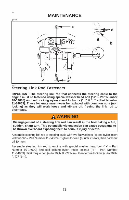
72
oh
MAINTENANCEgoh46
a
c
b
d
ohi1
Steering Link Rod FastenersIMPORTANT: The steering link rod that connects the steering cable to theengine must be fastened using special washer head bolt (“a” – Part Number10-14000) and self locking nylon insert locknuts (“b” & “c” – Part Number11-34863). These locknuts must never be replaced with common nuts (nonlocking) as they will work loose and vibrate off, freeing the link rod todisengage.
WARNINGDisengagement of a steering link rod can result in the boat taking a full,sudden, sharp turn. This potentially violent action can cause occupants tobe thrown overboard exposing them to serious injury or death.
Assemble steering link rod to steering cable with two flat washers (d) and nylon insertlocknut (“b” – Part Number 11-34863). Tighten locknut (b) until it seats, then back nutoff 1/4 turn.
Assemble steering link rod to engine with special washer head bolt (“a” – PartNumber 10-14000) and self locking nylon insert locknut (“c” – Part Number11-34863). First torque bolt (a) to 20 lb. ft. (27 N·m), then torque locknut (c) to 20 lb.ft. (27 N·m).
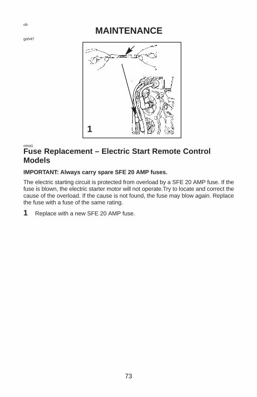
73
oh
MAINTENANCEgoh47
1
oma1
Fuse Replacement – Electric Start Remote ControlModelsIMPORTANT: Always carry spare SFE 20 AMP fuses.
The electric starting circuit is protected from overload by a SFE 20 AMP fuse. If thefuse is blown, the electric starter motor will not operate.Try to locate and correct thecause of the overload. If the cause is not found, the fuse may blow again. Replacethe fuse with a fuse of the same rating.
1 Replace with a new SFE 20 AMP fuse.
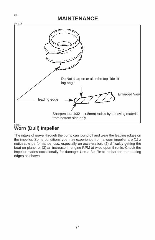
74
oh
MAINTENANCEgoh128
leading edge
Do Not sharpen or alter the top side lift-ing angle
Sharpen to a 1/32 in. (.8mm) radius by removing materialfrom bottom side only
Enlarged View
omm1
Worn (Dull) ImpellerThe intake of gravel through the pump can round off and wear the leading edges onthe impeller. Some conditions you may experience from a worn impeller are (1) anoticeable performance loss, especially on acceleration, (2) difficultly getting theboat on plane, or (3) an increase in engine RPM at wide open throttle. Check theimpeller blades occasionally for damage. Use a flat file to resharpen the leadingedges as shown.
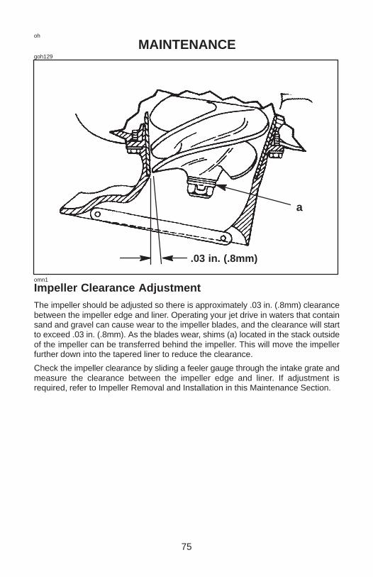
75
oh
MAINTENANCEgoh129
.03 in. (.8mm)
a
omn1
Impeller Clearance AdjustmentThe impeller should be adjusted so there is approximately .03 in. (.8mm) clearancebetween the impeller edge and liner. Operating your jet drive in waters that containsand and gravel can cause wear to the impeller blades, and the clearance will startto exceed .03 in. (.8mm). As the blades wear, shims (a) located in the stack outsideof the impeller can be transferred behind the impeller. This will move the impellerfurther down into the tapered liner to reduce the clearance.
Check the impeller clearance by sliding a feeler gauge through the intake grate andmeasure the clearance between the impeller edge and liner. If adjustment isrequired, refer to Impeller Removal and Installation in this Maintenance Section.
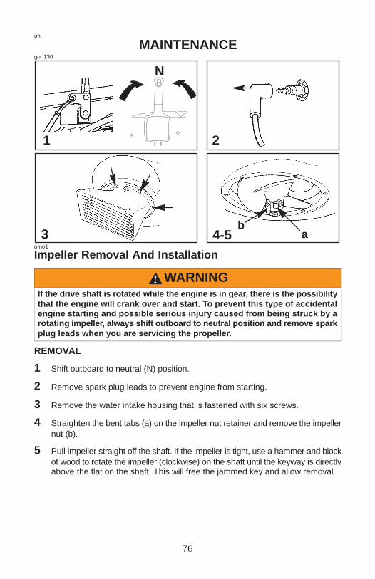
76
oh
MAINTENANCEgoh130
1 2
4-53
N
ab
omo1
Impeller Removal And Installation
WARNINGIf the drive shaft is rotated while the engine is in gear, there is the possibilitythat the engine will crank over and start. To prevent this type of accidentalengine starting and possible serious injury caused from being struck by arotating impeller, always shift outboard to neutral position and remove sparkplug leads when you are servicing the propeller.
REMOVAL
1 Shift outboard to neutral (N) position.
2 Remove spark plug leads to prevent engine from starting.
3 Remove the water intake housing that is fastened with six screws.
4 Straighten the bent tabs (a) on the impeller nut retainer and remove the impellernut (b).
5 Pull impeller straight off the shaft. If the impeller is tight, use a hammer and blockof wood to rotate the impeller (clockwise) on the shaft until the keyway is directlyabove the flat on the shaft. This will free the jammed key and allow removal.

77
oh
MAINTENANCEgoh131
6
7
.03 in. (.8mm)
a
c
b
def
omo2
Impeller Removal And Installation
INSTALLATION
6 Grease the drive shaft, shear key, and impeller bore. Place the plastic sleeve(a) inside the impeller (b) and install impeller, shear key (c), shims (d) nut retainer(e), and impeller nut (f). Turn the nut tight on the shaft to remove any playbetween the impeller and shaft. If the tabs on the retainer do not line up with theflats on the nut, remove the nut and turn the retainer over and re-tighten the nutagain.
7 Temporarily reinstall the water intake housing in order to check for impellerclearance. The clearance between the impeller and liner should be .030 in. (.8mm). Shim washers can be transferred to either side of the impeller to raise orlower the impeller to the correct clearance setting. The water intake housing canbe shifted side ways a small amount in order to center the casing liner.

78
oh
MAINTENANCEgoh132
8 9a
omo3
Impeller Removal And Installation
INSTALLATION (CONTINUED)
8 After setting the impeller height, tighten the impeller nut snug with a wrench.Secure impeller nut by bending tabs (a) against the flats on the impeller nut.
NOTE: If the outboard is used in salt water, apply Quicksilver or Mercury PrecisionAnti-Corrosion Grease around the entire mounting flange on the water intakehousing and also to the threads on the six mounting bolts.
9 Reinstall the water intake housing with six bolts. Check clearance around theimpeller to make sure the water intake housing is centered and not rubbingagainst the liner. Torque mounting bolts to 120 lbs. in. (13 N·M).

79
oh
MAINTENANCEgoh155
1-3
a
c
b
domp1
Shift Link Rod Adjustment
WARNINGThe shift link rod must be adjusted to lock the reverse gate againstunexpected engagement (caused by water pressure hitting the gate) whileoperating the boat in forward. Activation of the reverse gate will causesudden unexpected stopping of the boat. Sudden stopping may causeoccupants to be thrown within the boat or even out of the boat. This actionmay result in serious injury or death.
CHECKING SHIFT LINK ROD ADJUSTMENT
1 Check the shift link rod (a) adjustment in forward shift position. The correctadjustment will position the shift cam (b) far enough on the roller (c) in order tolock the the reverse gate (d) into forward position. You should not be able toforcibly push up the reverse gate toward neutral. Pull on the reverse gate byhand to verify this.
ADJUSTING SHIFT LINK ROD
2 Place the shift handle into full forward shift position.
3 Adjust the length of the shift link rod (a) so that roller (c) is at the full end of travel(bottom) in the shift cam (c) when the shift handle is in full forward.

80
ob
MAINTENANCEgoh133
1
acb
oho33
Lubrication Points
1 Lubricating the drive shaft bearing.
Recommended Lubrication - Use Quicksilver or Mercury Precision Lubricants2-4-C w/Teflon, or Lubriplate 630-AA Grease.
IMPORTANT: It is important that you do not use a general-all-purpose greasefor this bearing. The lubricant we recommend is a water resistant grease of theproper consistency for this application. If you use a substitute grease, be surethat it is water resistant and of the same consistency.
Frequency of lubrication - We recommend lubricating the drive shaft bearing aftereach day’s use and after every 10 hours of operation. After every 30 hours ofoperation, pump in extra grease to purge out any moisture.
Lubricating Procedure - Pull vent hose (a) off the grease fitting. Pump in grease (b)through the grease fitting (using the grease gun provided) until excess grease startsto exit the vent hose(c).
Reconnect the vent hose (a) onto the grease fitting after greasing.
After 30 hours of operation, pump in extra grease to purge out any moisture. Visuallyinspecting the purged grease at this time will give you an indication of conditionsinside the bearing housing. A gradual increase in moisture content, indicates sealwear. If the grease begins to turn dark, dirty gray, the drive shaft bearing and sealsshould be inspected and replaced if necessary. Some discoloration of the grease isnormal during the break-in period on a new set of seals.
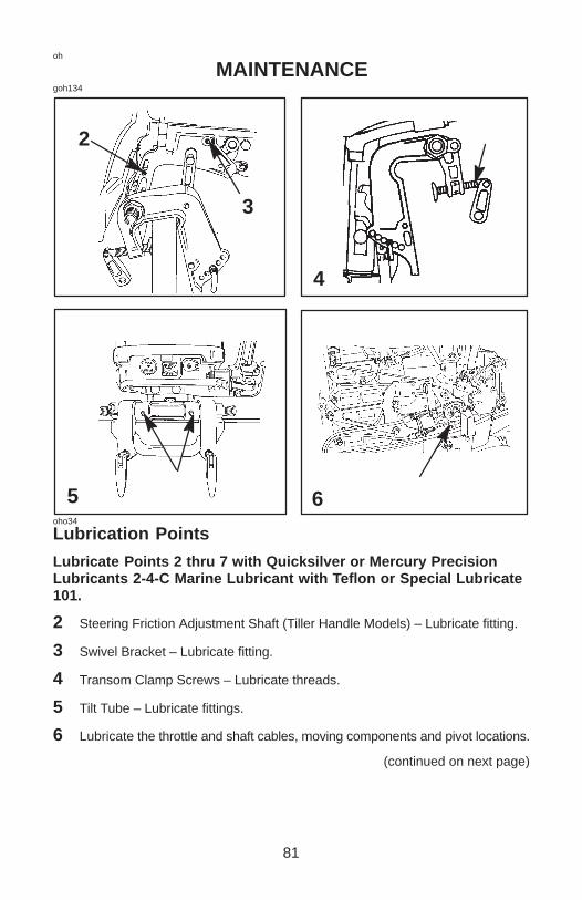
81
oh
MAINTENANCEgoh134
2
4
6
3
5oho34
Lubrication Points
Lubricate Points 2 thru 7 with Quicksilver or Mercury PrecisionLubricants 2-4-C Marine Lubricant with Teflon or Special Lubricate101.
2 Steering Friction Adjustment Shaft (Tiller Handle Models) – Lubricate fitting.
3 Swivel Bracket – Lubricate fitting.
4 Transom Clamp Screws – Lubricate threads.
5 Tilt Tube – Lubricate fittings.
6 Lubricate the throttle and shaft cables, moving components and pivot locations.
(continued on next page)

82
oh
MAINTENANCEgoh135
7-b
8
7-a
oho17
Lubrication Points (Continued)
WARNINGThe end of the steering cable must be fully retracted into the outboard tilttube before adding lubricant. Adding lubricant to steering cable when fullyextended could cause steering cable to become hydraulically locked. Anhydraulically locked steering cable will cause loss of steering control,possibly resulting in serious injury or death.
7 Steering Cable Grease Fitting (If Equipped) – Rotate steering wheel to fullyretract the steering cable end (a) into the outboard tilt tube. Lubricate throughfitting (b).
Lubricate points 8 With Light Weight Oil
8 Steering Link Rod Pivot Points – Lubricate points.

83
oh
MAINTENANCEgoh14
1 2 3
a
ohm16
Spark Plug Inspection and Replacement
WARNINGAvoid serious injury or death from fire or explosion caused by damagedspark plug boots (a). Damaged spark plug boots can emit sparks. Sparks canignite fuel vapors under the engine cowl. To avoid damaging spark plugboots, do not use any sharp object or metal tool such as pliers, screwdriver,etc. to remove spark plug boots.
1 Remove the spark plug boots (a) by twisting the rubber boots slightly and pulloff.
2 Remove the spark plugs to inspect. Replace spark plug if electrode is worn orthe insulator is rough, cracked, broken, blistered or fouled.
3 Set the spark plug gap. See Specification Chart in General Information Section.
4 Before installing spark plugs, clean away dirt on the spark plug seats. Installplugs finger tight, and tighten 1/4 turn or torque to 20 lb. ft. (27 N·m).
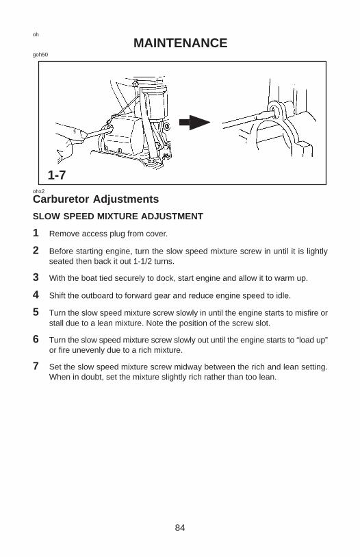
84
oh
MAINTENANCEgoh50
1-7ohx2
Carburetor Adjustments
SLOW SPEED MIXTURE ADJUSTMENT
1 Remove access plug from cover.
2 Before starting engine, turn the slow speed mixture screw in until it is lightlyseated then back it out 1-1/2 turns.
3 With the boat tied securely to dock, start engine and allow it to warm up.
4 Shift the outboard to forward gear and reduce engine speed to idle.
5 Turn the slow speed mixture screw slowly in until the engine starts to misfire orstall due to a lean mixture. Note the position of the screw slot.
6 Turn the slow speed mixture screw slowly out until the engine starts to “load up”or fire unevenly due to a rich mixture.
7 Set the slow speed mixture screw midway between the rich and lean setting.When in doubt, set the mixture slightly rich rather than too lean.
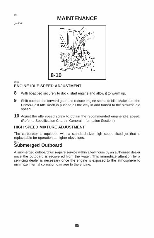
85
oh
MAINTENANCEgoh136
8-10ohu3
ENGINE IDLE SPEED ADJUSTMENT
8 With boat tied securely to dock, start engine and allow it to warm up.
9 Shift outboard to forward gear and reduce engine speed to idle. Make sure thePrimer/Fast Idle Knob is pushed all the way in and turned to the slowest idlespeed.
10 Adjust the idle speed screw to obtain the recommended engine idle speed.(Refer to Specification Chart in General Information Section.)
HIGH SPEED MIXTURE ADJUSTMENT
The carburetor is equipped with a standard size high speed fixed jet that isreplaceable for operation at higher elevations.ohr1
Submerged OutboardA submerged outboard will require service within a few hours by an authorized dealeronce the outboard is recovered from the water. This immediate attention by aservicing dealer is necessary once the engine is exposed to the atmosphere tominimize internal corrosion damage to the engine.
86
oi
STORAGEoia2
Storage PreparationThe major consideration in preparing your outboard for storage is to protect it fromrust, corrosion, and damage caused by freezing of trapped water.
The following storage procedures should be followed to prepare your outboard forout of season storage or prolonged storage (two months or longer).
�����
Never start or run your outboard (even momentarily) without water circulat-ing through all the cooling water intake holes in the gear case to preventdamage to the water pump (running dry) or overheating of the engine.
oib3
FUEL SYSTEM
IMPORTANT: Gasoline containing alcohol (ethanol or methanol) can cause aformation of acid during storage and can damage the fuel system. If thegasoline being used contains alcohol, It is advisable to drain as much of theremaining gasoline as possible from the fuel tank, remote fuel line, and enginefuel system.
Fill the fuel system (tank, hoses, fuel pump, and carburetor) with treated (stabilized)fuel to help prevent formation of varnish and gum. Proceed with followinginstructions.
1. Portable Fuel Tank – Pour the required amount of gasoline stabilizer (followinstructions on container) into fuel tank. Tip fuel tank back and forth to mixstabilizer with the fuel.
2. Permanently Installed Fuel Tank – Pour the required amount of gasolinestabilizer (follow instructions on container) into a separate container and mixwith approximately one quart (one liter) of gasoline. Pour this mixture into fueltank.
3. Place the outboard in water. Run the engine for ten minutes to allow treated fuelto reach the carburetor.
87
oi
STORAGEoic4
PROTECTING EXTERNAL OUTBOARD COMPONENTS
4. Lubricate all outboard components listed in the Inspection and MaintenanceSchedule.
5. Touch up any paint nicks. See your dealer for touch-up paint.
6. Spray Quicksilver or Mercury Precision Lubricants Corrosion Guard on externalmetal surfaces (except corrosion control anodes).
oid3
PROTECTING INTERNAL ENGINE COMPONENTS
NOTE: Before performing Steps 7 and 8, make sure the fuel system has beenprepared for storage. Refer to Fuel System on previous page.
7. Place the outboard in water. Start the engine and let it run in neutral to warm up.
8. With engine running at fast idle, stop the fuel flow by disconnecting the remotefuel line. When engine begins to stall, quickly spray Quicksilver or MercuryPrecision Lubricants Storage Seal into carburetor until engine stops from lackof fuel.
9. Remove the spark plugs and inject a five second spray of storage seal aroundthe inside of each cylinder.
10. Rotate the flywheel manually several times to distribute the storage seal in thecylinders. Reinstall spark plugs.
oih1
JET DRIVE
11. Pump extra grease into the jet drive bearing to purge out moisture.

88
oi
STORAGEoif3
POSITIONING OUTBOARD FOR STORAGE
Store outboard in an upright (vertical) position to allow water to drain out of outboard.oig1
BATTERY STORAGE
1. Follow the battery manufacturers instructions for storage and recharging.
2. Remove the battery from the boat and check water level. Recharge if necessary.
3. Store the battery in a cool, dry place.
4. Periodically check the water level and recharge the battery during storage.

89
oj
TROUBLESHOOTINGojc1
1 – STARTER MOTOR WILL NOT CRANK THE ENGINE(ELECTRIC START MODELS)
POSSIBLE CAUSES
• Remote control models – Blown 20 Amp fuse in the starting circuit. Refer toMaintenance Section
• Outboard is not shifted to neutral position.
• Weak battery or battery connections are loose or corroded.
• Ignition key switch failure.
• Wiring or electrical connection faulty.
• Starter motor or starter solenoid failure.
2 – ENGINE WILL NOT STARTPOSSIBLE CAUSES
• Lanyard stop switch not in RUN position.
• Incorrect starting procedure. Refer to Operating Section.
• Old or contaminated gasoline.
• Engine flooded. Refer to Operating Section.
• Fuel is not reaching the engine.
a. Fuel tank is empty.
b. Fuel tank vent not open or restricted.
c. Fuel line is disconnected or kinked.
d. Primer bulb not squeezed.
e. Primer bulb check valve is faulty.
f. Fuel filter is obstructed. Refer to Maintenance Section.
g. Fuel pump failure.
h. Fuel tank filter obstructed.
• Ignition system component failure
• Spark plugs fouled or defective. Refer to Maintenance Section.

90
oj
TROUBLESHOOTING3 – ENGINE RUNS ERRATICALLYPOSSIBLE CAUSES
• Spark plugs fouled or defective. Refer to Maintenance Section.
• Incorrect setup and adjustments.
• Fuel is being restricted to the engine.
a. Engine Fuel filter is obstructed. Refer to Maintenance Section.
b. Fuel tank filter obstructed.
c. Stuck anti-siphon valve located on permanently built in type fuel tanks.
d. Fuel line is kinked or pinched.
• Fuel pump failure.
• Ignition system component failure.
4 – ENGINE OVER-SPEED (EXCESSIVE RPM)POSSIBLE CAUSES
• Outboard mounted too high on the transom.
• Worn jet pump impeller or liner.
• Incorrect jet pump impeller clearance adjustment.
• Tilting the outboard out beyond a vertical position.
• Cavitation of the impeller due to rough water or obstruction in the boat hull.
5 – BATTERY WILL NOT HOLD CHARGEPOSSIBLE CAUSES
• Battery connections are loose or corroded.
• Low electrolyte level in battery.
• Worn out or inefficient battery.
• Excessive use of electrical accessories.
• Defective rectifier, alternator, or voltage regulator.

91
OWNER SERVICE ASSISTANCEor6
Local Repair ServiceAlways return your outboard to your local authorized dealer should the need forservice arise. Only he has the factory-trained mechanics, knowledge, special toolsand equipment and the genuine parts and accessories to properly service yourengine should the need occur. He knows your engine best.or2
Service Away From HomeIf you are away from your local dealer and the need arises for service, contact thenearest authorized dealer. Refer to the Yellow Pages of the telephone directory. If,for any reason, you cannot obtain service, contact the nearest Mercury MarineService Office.or7
Parts And Accessories InquiriesAll inquiries concerning genuine replacement parts and accessories should bedirected to your local authorized dealer. The dealer has the necessary informationto order parts and accessories for you. When inquiring on parts and accessories, thedealer requires the model and serial number to order the correct parts.

EXTRA HELP
92
OWNER SERVICE ASSISTANCEor4
Service AssistanceYour satisfaction with your outboard product is very important to your dealer and tous. If you ever have a problem, question or concern about your outboard product,contact your dealer or any Authorized Mercury Marine Dealership. If additionalassistance is required, take these steps.
1. Talk with the dealership’s sales manager orservice manager. If this has already beendone, then contact the owner of thedealership.
2. Should you have a question, concern orproblem that cannot be resolved by yourdealership, please contact Mercury MarineService Office for assistance. MercuryMarine will work with you and yourdealership to resolve all problems.
The following information will be needed by the service office:
• Your name and address
• Daytime telephone number
• Model and serial number of your outboard
• The name and address of your dealership
• Nature of problem
Mercury Marine Service Offices are listed on the next page.
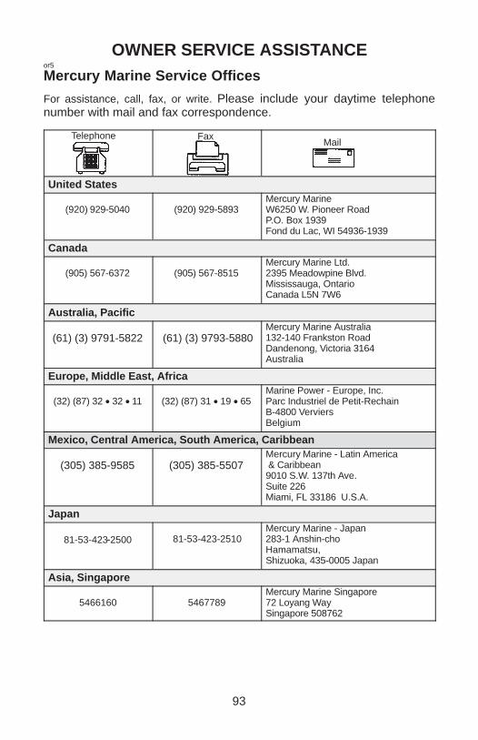
93
OWNER SERVICE ASSISTANCEor5
Mercury Marine Service Offices
For assistance, call, fax, or write. Please include your daytime telephonenumber with mail and fax correspondence.
Telephone FaxMail
United States
(920) 929-5040 (920) 929-5893Mercury MarineW6250 W. Pioneer RoadP.O. Box 1939Fond du Lac, WI 54936-1939
Canada
(905) 567-6372 (905) 567-8515Mercury Marine Ltd.2395 Meadowpine Blvd.Mississauga, OntarioCanada L5N 7W6
Australia, Pacific
(61) (3) 9791-5822 (61) (3) 9793-5880Mercury Marine Australia132-140 Frankston RoadDandenong, Victoria 3164Australia
Europe, Middle East, Africa
(32) (87) 32 • 32 • 11 (32) (87) 31 • 19 • 65Marine Power - Europe, Inc.Parc Industriel de Petit-RechainB-4800 VerviersBelgium
Mexico, Central America, South America, Caribbean
(305) 385-9585 (305) 385-5507Mercury Marine - Latin America & Caribbean9010 S.W. 137th Ave.Suite 226Miami, FL 33186 U.S.A.
Japan
81-53-423-2500 81-53-423-2510Mercury Marine - Japan283-1 Anshin-choHamamatsu,Shizuoka, 435-0005 Japan
Asia, Singapore
5466160 5467789Mercury Marine Singapore72 Loyang WaySingapore 508762

94
MAINTENANCE LOGoka1
Maintenance LogRecord here all maintenance performed on your outboard. Be sure to save all workorders and receipts.
Date Maintenance PerformedEngineHours

95
MAINTENANCE LOG
Date Maintenance PerformedEngineHours