
MerCruiser 60,80 and 90 Engines - Lotus Europa Central 60-80... · MERCRUISER 60, 80 AND 90 ENGINES...
34
Chapter Nine MerCruiser 60, 80 and 90 Engines This chapter covers the early MerCruiser 4-cylinder inline engines manufactured by Renault. Although differing in displacement, these engines share many features. All use an aluminum block of sleeved design, with removable cylinder liners. The 60 combines an alternator stator with a front flywheel; the 80 and 90 flywheel contains an alternator rotor. The 60 and 80 cylinder head contains intake and exhaust valves mounted inline; the 90 is a crossflow design, with intake valves on one side and exhaust valves on the other. Rocker arms are retained on a rocker arm shaft, with camshaft motion transferred to the rocker arms by pushrods. The cylinders are numbered 4-3-2-l from front to rear. Engine firing order is l-3-4-2. The 80 and 90 are mounted with the front of the engine facing the transom. The crankshaft is supported by 5 main bearings, with washers in the center main bearing taking the thrust. Crankshaft rotation is counterclockwise when seen from the front of the engine. The block is line-bored to accept the chain-driven camshaft located above the crankshaft in the engine block. The oil pump is flange-mounted on the block and driven by the distributor shaft. Specifications (Table 1) and tightening torques (Table 2) are at the end of the chapter. ENGINE SERIAL NUMBER The engine serial number is stamped on a plate mounted on the left side of the engine block above the oil filter on MerCruiser 60 engines (Figure 1) and on the left rear side of the engine block under the intake manifold on 80 and 90 engines (Figure 2). This information identifies the engine and indicates if there are unique parts or if internal changes have been made during the model run. It is important when ordering replacement parts for the engine. SPECIAL TOOLS Where special tools are required or recommended for engine overhaul, the tool numbers are provided. While these tools can sometimes be rented from rental dealers, they can always be purchased from your MerCruiser dealer.
Transcript of MerCruiser 60,80 and 90 Engines - Lotus Europa Central 60-80... · MERCRUISER 60, 80 AND 90 ENGINES...

Chapter Nine
MerCruiser 60, 80 and 90 Engines
This chapter covers the early MerCruiser4-cylinder inline engines manufactured by Renault.Although differing in displacement, these enginesshare many features.
All use an aluminum block of sleeved design,with removable cylinder liners. The 60 combinesan alternator stator with a front flywheel; the 80and 90 flywheel contains an alternator rotor.
The 60 and 80 cylinder head contains intake andexhaust valves mounted inline; the 90 is acrossflow design, with intake valves on one sideand exhaust valves on the other. Rocker arms areretained on a rocker arm shaft, with camshaftmotion transferred to the rocker arms by pushrods.
The cylinders are numbered 4-3-2-l from frontto rear. Engine firing order is l-3-4-2. The 80 and90 are mounted with the front of the engine facingthe transom.
The crankshaft is supported by 5 main bearings,with washers in the center main bearing taking thethrust. Crankshaft rotation is counterclockwisewhen seen from the front of the engine.
The block is line-bored to accept thechain-driven camshaft located above thecrankshaft in the engine block.
The oil pump is flange-mounted on the blockand driven by the distributor shaft.
Specifications (Table 1) and tightening torques(Table 2) are at the end of the chapter.
ENGINE SERIAL NUMBER
The engine serial number is stamped on a platemounted on the left side of the engine block abovethe oil filter on MerCruiser 60 engines (Figure 1)and on the left rear side of the engine block underthe intake manifold on 80 and 90 engines (Figure2).
This information identifies the engine andindicates if there are unique parts or if internalchanges have been made during the model run. It isimportant when ordering replacement parts for theengine.
SPECIAL TOOLS
Where special tools are required orrecommended for engine overhaul, the toolnumbers are provided. While these tools cansometimes be rented from rental dealers, they canalways be purchased from your MerCruiser dealer.

MERCRUISER 60. 80 AND 90 ENGINES 219
REPLACEMENT PARTS
Various changes are made to automotive engineblocks used for marine applications. Numerouspart changes are required due to operation in freshand salt water. For example, the cylinder headgasket must be corrosion-resistant. Marine enginesuse head gaskets of copper or stainless steel insteadof the standard steel-type used in automotiveapplications. Brass expansion or core plugs must beused instead of the steel plugs found in automotiveblocks.
Since marine engines are run at or nearmaximum rpm most of the time, the use of specialvalve lifters, springs, pistons, bearings, camshaftsand other heavy-duty moving components isnecessary for maximum life and performance.
MERCRUISER 60 SERIAL NO. LOCATION
Engine serial No.
.02 MERCRUISER 80 AND 90
SERIAL NO. LOCATION
Engine serial No. \
For these reasons, automotive-type parts shouldnot be substituted for marine components. Inaddition, Mercury recommends that onlyQuicksilver parts be used. Parts offered by othermanufacturers may look alike, but may not bemanufactured to Mercury’s specifications. Anydamage resulting from the use of other thanQuicksilver parts is not covered by the MercuryMarine warranty.
REMOVAL
Some service procedures can be performed withthe engine in the boat; others require removal. Theboat design and service procedure to be performedwill determine whether the engine must beremoved. In some installations, it may benecessary to remove the stem drive unit first. SeeChapter Fourteen.
WARNINGThe engine is heavy, awkward to handle and hassharp edges. It may shift or drop suddenly duringremoval. To prevent serious injury, alwaysobserve the following precautions.1. Never place any part of your body where amoving or falling engine may trap, cut or crushyou.2. If you must push the engine during removal,use a board or similar tool to keep your handsout of danger.3. Be sure the hoist is designed to lift enginesand has enough load capacity for your engine.4. Be sure the hoist is securely attached to safelifting points on the engine.5 . The engine should not be dtficult to lift with aproper hoist. If it is, stop lifting, lower the engineback onto its mounts and make sure the enginehas been completely separated from the boat.
1. Remove the engine hood cover and any panelsthat interfere with engine removal. Place to oneside out of the way.2. Disconnect the negative battery cable, then thepositive battery cable. As a precaution, remove thebattery from the boat.3. Disconnect the instrument panel harness plug atthe harness receptacle.4. Disconnect the fuel line, throttle and shiftcontrol cables. Plug the fuel line to prevent leakage.5. Disconnect the Ride-Guide steering cable at thesteering rod.6. Loosen the steering rod-to-clevis locknut.Remove the cotter pin, washer and clevis pin andseparate clevis from steering arm.

220 CHAPTER NINE
7A. MerCruiser 60-disconnect the tilt switchleads at the ignition coil and condenser mountingbracket. See Figure 3.7B. MerCruiser 80 and 90-disconnect the tiltswitch and ground leads from the starter solenoidand engine harness. See Figure 4.8. Remove the hydraulic ‘shift unit from themounting bracket/shift lever without disconnectingthe hydraulic lines. See Figure 5 (MerCruiser 60) orFigure 6 (MerCruiser 80 and 90).9. Attach a lifting bracket to the engine lifting eyes.Connect the bracket to an engine hoist and elevateit enough to remove all slack.10. Remove the nuts/washers from the lowertransom plate screws, then remove the screws(Figure 7).11. Remove manual tilt-up cable from stem driveunit top cover.12. Remove nuts/washers from the upper transomscrews. Remove screws and manual tilt-up unitfrom transom. See Figure 8 (MerCruiser 60) orFigure 9 (MerCruiser 80 and 90).13. Disconnect any accessories connected to theengine that will interfere with removal.
03
MERCRUISER 80 TILT SWITCH LEADS
-lHI Condenser mounting \1 bracket
Coil terminal
MERCRUISER 80 AND 80TILT SWITCH LEADS
Disconnect ground le
MERCRUISER 80 HYDRAULIC SHIFT UN11
Mounting plate
Shift lever
0 MERCRUISER 80 AND 806 HYDRAULIC SHIFT UNIT

MERCRUISER 60, 80 AND 90 ENGINES 221
MERCRUISER 80 AND 90BOTTOM MOUNTING BOLTS I
Elastic nuts and washers
MERCRUISER 60 MANUAL TILT-UP UNITHydraulic shift mounting plate
MANUAL TILT=UP UNIT
N O T EAt this point, there should be no hoses, wires orlinkage connecting the engine to the boat orstern drive unit. Recheck this to make surenothing will hamper engine removal.
14. Slide the engine forward sufficiently todisengage the inner transom plate from the sterndrive unit.IS. Drain the engine coolant and crankcase oil.16. Remove the engine from the boat with thehoist.
ENGINE INSTALLATION
1. Install gimbal housing, if removed.2. Coat the water tube, guide bar and exhaust tubewith Multipurpose Lubricant (part No.C-92-63250). See Figure 10.3. Align exhaust tube and guide bar on innertransom plate with the bar groove and tubeopening on the gimbal housing.
CA UTIONDo not rock engine from side to side in Step 4 orthe water tube seal in the inner transom platemay be damaged, resulting in a water leak.
4. Make sure water tube enters inner transom platehole as engine is guided into place.

222 CHAPTER NINE
N O T ERoute power tilt hose on MerCruiser 60 and 80to port side of engine in Step 5.
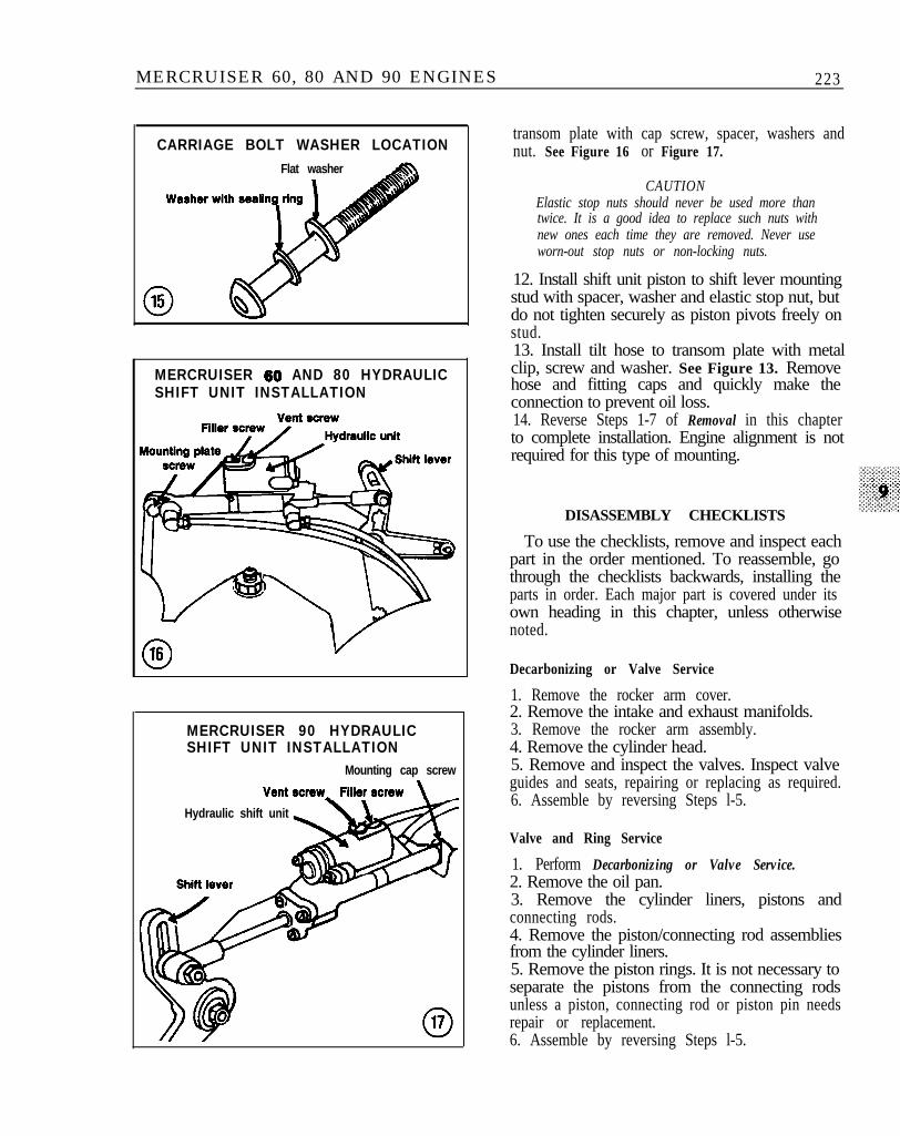
5. From outside the boat, install the manual tiltunit (Figure 11) or hydraulic inlet cover (Figure 12)with hoses through the transom opening. Move thehydraulic shift unit mounting plate up or down asrequired to provide clearance for tilt unit. SeeFigure 13.6. Install washers on 2 carriage bolts (Figure 14 orFigure 15) and install bolts from outside of boatthrough the tilt unit, transom and inner transomplate.
CA UTIONOnly early units require the sealing washershown in Figure 15. Keep transom seal in placewhen tightening the bolts. Elastic stop nutsshould never be used more than twice. It is agood idea to replace such nuts with new oneseach time they are removed. Never use worn-outstop nuts or non-locking nuts.
7. Place a flat washer and elastic stop nut on eachbolt. Hold bolt head with a 5/16 in. Allen wrenchand tighten nut to 20-25 ft.-lb.8. Repeat Step 6 and Step 7 to install 2 boltsthrough bottom holes of gimbal housing, transomand inner transom plate.9. Relieve hoist tension and remove from engine.10. MerCruiser 60 and 80 only-install shift unitmounting plate to inner transom plate screws andtighten securely.11. Position hydraulic shift unit piston to shiftlever stud. Install shift unit to mounting or
MANUAL TILT=UP INSTALLATIONHydraulic shift mounting plate
Elastic nuts an
012 INLET COVER INSTALLATION
and D-washer
lo13 HYDRAULIC POWER TILTHOSECONNECTORS
CARRIAGE BOLT WASHER LOCATION
Transom mounting hole
014
MERCRUISER 60, 80 AND 90 ENGINES 223
CARRIAGE BOLT WASHER LOCATIONFlat washer
MERCRUISER 60 AND 80 HYDRAULICSHIFT UNIT INSTALLATION
MERCRUISER 90 HYDRAULICSHIFT UNIT INSTALLATION
Mounting cap screw
Hydraulic shift unit
transom plate with cap screw, spacer, washers andnut. See Figure 16 or Figure 17.
CAUTIONElastic stop nuts should never be used more thantwice. It is a good idea to replace such nuts withnew ones each time they are removed. Never useworn-out stop nuts or non-locking nuts.
12. Install shift unit piston to shift lever mountingstud with spacer, washer and elastic stop nut, butdo not tighten securely as piston pivots freely onstud.13. Install tilt hose to transom plate with metalclip, screw and washer. See Figure 13. Removehose and fitting caps and quickly make theconnection to prevent oil loss.14. Reverse Steps 1-7 of Removal in this chapterto complete installation. Engine alignment is notrequired for this type of mounting.
DISASSEMBLY CHECKLISTS
To use the checklists, remove and inspect eachpart in the order mentioned. To reassemble, gothrough the checklists backwards, installing theparts in order. Each major part is covered under itsown heading in this chapter, unless otherwisenoted.
Decarbonizing or Valve Service
1. Remove the rocker arm cover.2. Remove the intake and exhaust manifolds.3. Remove the rocker arm assembly.4. Remove the cylinder head.5. Remove and inspect the valves. Inspect valveguides and seats, repairing or replacing as required.6. Assemble by reversing Steps l-5.
Valve and Ring Service
1. Perform Decarbonizing or Valve Service.2. Remove the oil pan.3. Remove the cylinder liners, pistons andconnecting rods.4. Remove the piston/connecting rod assembliesfrom the cylinder liners.5. Remove the piston rings. It is not necessary toseparate the pistons from the connecting rodsunless a piston, connecting rod or piston pin needsrepair or replacement.6. Assemble by reversing Steps l-5.

224 CHAPTER NINE
General Overhaul
1. Remove the engine from the boat.2. Remove the flywheel.3. Remove the engine mount brackets and oilpressure sending unit from the engine.4. If available, mount the .engine on an enginestand. These can be rented from equipment rentaldealers. The stand is not absolutely necessary, butit will make the job much easier.5. Check the engine for signs of coolant or oilleaks.6. Clean the outside of the engine.7. Remove the distributor. See Chapter Thirteen.8. Remove all hoses and tubes connected to theengine.9. Remove the fuel pump. See Chapter Eleven.10. Remove the intake and exhaust manifolds.11. Remove the thermostat. See Chapter Twelve.12. Remove the rocker arm assembly.13. Remove the front cover. Remove the timinggear and sprockets.14. Remove the cylinder head.15. Remove the camshaft.16. Remove the oil pan and oil pump.17. Remove the cylinder liners, pistons andconnecting rods.18. Remove the crankshaft.19. Inspect the cylinder block.20. Assemble by reversing Steps 1- 18.
ROCKER ARM COVER
Removal/Installation
1. Remove the crankcase vent line from the rockerarm cover.2. On MetCruiser 90, disconnect the spark plugwires and remove retaining clips from rocker armcover.3. Remove the cover attaching nuts. Tap therocker arm cover with a plastic mallet to break thegasket seal. Remove the rocker arm cover.4. Clean any gasket residue from the cylinder headand rocker arm cover with degreaser and a puttyknife.5. Install the cover on the cylinder head with a newgasket.6. Install the attaching nuts and tighten tospecifications (Table 3).7. Install the crankcase vent line in the rocker armcover.8. On Met-Cruiser 90, install spark plug wires.
I MERCRUISER 90 INTAKE YANlFOLD
so hole is open
INTAKE/EXHAUST MANIFOLDS
MerCruiser 60 and 90 engines use separateintake and exhaust manifolds; the MerCruiser 80manifolds are combined in a single unit.
Intake ManifoldRemoval/Installation(MerCruiser 60 and 90)
1. Disconnect the negative battery cable.2. Disconnect the fuel line at the carburetor. Plugthe line to prevent leakage.3. Disconnect the choke heat tube, if so equipped.4. Disconnect the throttle cable at the carburetorand remove the return spring. Disconnect the fuelline clamp.5. Remove the crankcase vent line at the rockerarm cover.6. Disconnect the manifold cooling hose at thebottom of the manifold.7. Remove manifold attaching nuts. Remove themanifold assembly with carburetor attached.Discard the manifold gasket.8. Clean all gasket residue from the cylinder headand manifold mating surfaces with degreaser and aputty knife.9. Install a new manifold gasket on the cylinderhead. Gasket must be positioned on 90 engines sothat only the hole shown in Figure 18 is open tocooling water.10. Install manifold to head and tighten fastenersto specifications (Table 2) working from the centerto the ends. The remainder of installation is thereverse of removal.

MERCRUISER 60, 80 AND 90 ENGINES 225
019 ENGINE MOUNT SCREWS
Lower engine mount screws
Exhaust ManifoldRemoval/Installation(MerCruiser 60 and 90)
1. Remove bolts holding electrical panel tomanifold.2. On MerCruiser 60, disconnect cooling hoses andchoke assembly.3. Remove exhaust outlet hose.4. Remove manifold attaching nuts. Remove themanifold assembly and discard the gasket.5. Clean all gasket residue from the cylinder headand manifold mating surfaces with degreaser and aputty knife.6. Install a new manifold gasket on the cylinderhead.7. Install manifold to head and tighten fasteners tospecifications (Table 2) working from the center tothe ends. The remainder of installation is thereverse of removal.
Intake/Exhaust ManifoldRemoval/Installation(MerCruiser 80)
1. Disconnect manifold cooling hoses.2. Remove wiring harness and electricalcomponent bracket from the manifold.3. Remove manifold attaching nuts. Remove themanifold assembly with carburetor attached.Discard the manifold gasket.
4. Clean all gasket residue from the cylinder headand manifold mating surfaces with degreaser and aputty knife.5. Install a new manifold gasket on the cylinderhead.6. Install manifold to head and tighten fasteners tospecifications (Table 2) working from the center tothe ends. The remainder of installation is thereverse of removal.
Intake/ExhaustManifold Inspection
1. Remove carburetor from intake manifold.2. Check manifold for cracks or distortion.Replace as required.3. Check mating surfaces for nicks, burrs or deepscratches. Small burrs may be removed with anoilstone.4. Check water passages for sand, silt or othercontamination. Clean as required.5. Remove pipe plugs from exhaust manifoldelbow and exhaust pipe elbow. Check forcontamination and clean as required.6. Inspect engine exhaust ports for signs of rust orcorrosion. Replace manifold if such signs arefound.
INNER TRANSOM PLATE
Removal/Installation
1. Remove engine from boat as described in thischapter.2. Remove interlock nut/bolt at base of transomplate.3. Disconnect wires and harness leads connectedto transom plate.4. Disconnect and remove water inlet hose at rearof engine block.5. Loosen exhaust bellows-to-manifold clamp.6. Remove lower engine mount-to-transom platescrews. See Figure 19.7. Remove large Ride-Guide steering tube nut.Remove tube from support.8. Remove transom plate by pulling outward anddown.

226 CHAPTER NINE
9. Remove large washers on each side ofRide-Guide tube support.10. Remove upper engine mount-to-cylinder headbracket.11. Installation is the reverse of removal.
FRONT COVER AND SEAL
Removal/Installation(MerCruiser 60)
1. Remove alternator flywheel and stator asdescribed in this chapter.2. Remove cover attaching screws. Remove thecover and gasket. Discard the gasket.3. Clean all gasket residue from cover and engineblock mating surfaces.4. Install cover with a new gasket. Do not tightenscrews at this time.5. Install alternator flywheel on crankshaft to alignoil seal.6. Tighten cover screws securely and removeflywheel.7. Install alternator flywheel and stator asdescribed in this chapter.
Removal/Installation(MerCruiser 80 and 90)
1. Remove the cover attaching bolts.2. Remove the cover and gasket. Discard thegasket.3. Clean all gasket residue from the cover andengine block mating surfaces.4. Install the cover with a new gasket. Tightencover bolts to specifications (Table 2).
Seal Replacement
1. Remove front cover as described in this chapter.2. Place cover on a clean flat workbench surface.3. Pry old seal from cover with a screwdriver.4. Clean the seal recess in the cover with solventand blow dry.5. Position new seal in cover recess with seal lipsfacing toward timing chain. Support cover at sealarea and drive seal into place with appropriate sizeinstaller. See Figure 20.6. Install front cover as described in this chapter.
ROCKER ARM ASSEMBLY
Removal/Installation
1. Remove the rocker arm cover as described inthis chapter.
020TIMING CHAIN COVER
OIL SEAL INSTALLATION
2. Remove the bolts holding the rocker armshaft(s) in place.3. Remove rocker arm assembly.4. Remove the pushrods and place in order ofremoval for reinstallation in the same positionfrom which they were removed.5. Installation is the reverse of removal. OnMetCruiser 90 engines, install rocker arms andtorque bolts to specifications (Table 2), then loosenand install pushrods. Adjust valve clearance withengine stopped, as described in this chapter.
Inspection
1. Grasp each rocker arm and twist it. If there isany rocking motion (not sliding), have the rockerarms and shaft checked for wear by a machineshop.2. Remove the pin or keeper holding the rockerarm shaft in the mount. Slide shaft from mount.3. Mark position of rocker arms and springs forreinstallation in the same position from which theywere removed.4. Clean all parts thoroughly in solvent. Usecompressed air to blow out the oil passages in thepushrods. Inspect pushrods for damage andexcessive wear (0.002 in. or greater). Replacedamaged or worn parts.

MERCRUISER 60, 80 AND 90 ENGINES 227
MERCRUISER 60
5. Check rocker arm contact surfaces for scuffing,pitting or excessive wear. Slight wear marks may beremoved with an oilstone.6. Check pushrods for straightness by rolling themacross a flat, even surface such as a pane of glass.Replace pushrods that do not roll smoothly.7. If a pushrod is worn from lack of lubrication,replace the corresponding tappet and rocker arm aswell.
CAMSHAFT AND TIMING CHAIN
Lobe Lift Measurement
Camshaft lobe lift can be measured with thecamshaft in the block and the cylinder head inplace.
1. Remove the rocker arm cover as described inthis chapter.2. Remove the rocker arm assembly as describedin this chapter.3. Remove the spark plugs.4. Install a dial indicator with a ball socket adapterto fit over the pushrod. See Figure 21.5. Turn the crankshaft in the normal direction ofrotation until the valve tappet seats on the heel ofthe cam lobe. This positions the pushrod at itslowest point.6. Zero the dial indicator, then slowly rotate thecrankshaft until the pushrod reaches its maximumtravel. Note the indicator reading and compare tospecifications (Table 1).7. Repeat Steps 4-6 for each pushrod. If all lobesare within specifications, reinstall the rocker armassemblies and adjust the valves as described inthis chapter.8. If one or more lobes are worn beyondspecifications, replace the camshaft as described inthis chapter.9. Remove the dial indicator and reverse Steps1-3.
Removal(MerCruiser 60)
1. Remove the alternator flywheel and stator asdescribed in this chapter.2. Remove the cylinder head as described in thischapter.3. Remove the front cover as described in thischapter.4. Remove the distributor. See Chapter Thirteen.5. Remove the oil pump drive pinion with apencil-type magnet.6. Remove the valve tappets and place in a rack orother container in the order removed so they maybe reinstalled in their original locations.7. Unlock and remove the screw at the rear of thetensioner. Release the tension on the chain with aNo. 3 Allen wrench and remove tensionerassembly. See Figure 22.8. Bend the tab washer back and remove the lockscrew from the camshaft sprocket. See Figure 22.9. Remove the camshaft and crankshaft sprocketswith the timing chain. Remove the key from thecrankshaft.

228 CHAPTER NINE
10. Remove the 2 screws holding the camshaftthrust plate in place (Figure 23). Carefullywithdraw the camshaft from the block to preventdamage to the camshaft or block.
Installation(MerCruiser 60)
1. Coat the camshaft lobes and journals withheavy engine oil and reinstall in the block.2. Install and securely tighten the thrust platescrews.3. Install the key in the crankshaft keyway, theninstall the crankshaft sprocket.4. Position camshaft sprocket and align thereference marks on the 2 sprockets with thecamshaft and crankshaft centerlines.
N O T EWhen the chain is installed in Step 5, thereference marks aligned in Step 5 will not alignwith the camshaft axis due to the normal slackin the chain. See Figure 24.
5. Remove the camshaft sprocket. Install thetiming chain on the camshaft sprocket and reinstallsprocket/chain assembly. Tighten the camshaftsprocket locking screw and bend the tab washerover the camshaft screw.6. Install front cover as described in this chapter.7. Install cylinder head as described in thischapter.8. Rotate crankshaft 360’ to position the No. 1
piston at TDC. No. 4 cylinder valves should bepartially open and the alternator flywheel/frontcover timing marks should align.9. Install oil pump drive pinion. Slot in gearshould be at a right angle to the engine centerline,with large offset facing dipstick. See Figure 25.10. Remove distributor cap. Align rotor with No.1 spark plug terminal in cap.11. Install distributor to engine block. It may benecessary to turn the rotor slightly to seat thedistributor shaft in the oil pump drive pinion slot.12. Rotate distributor housing until breaker pointsjust start to open and tighten the hold-down clamp.13. Reinstall distributor cap. Make sure rotorpoints to No. 1 terminal in the cap.
0231
024

MERCRUISER 60, 80 AND 90 ENGINES 229
326
UERCRUISER 80 AND 90 TIMING MARKS
Camshaft flange bolts
Thrust washer
Removal(MerCruiser 80 and 90)
1. Remove cylinder head as described in thischapter.2. Remove front cover as described in this chapter.3. Remove crankshaft sprocket retaining bolt andthrust washer. See Figure 26.4. Remove chain tensioner bolts.5. Remove distributor drive pinion gear from theblock.6. Rotate the camshaft slightly as necessary andremove the flange bolts through the holes in thesprocket. See Figure 26.7. Check to see if crankshaft sprocket will slide off.If not, install an appropriate puller and loosensprocket. Pull camshaft and crankshaft sprocketforward with the chain as an assembly and removefrom the engine.
Installation(MerCruiser 80 and 90)
1. Coat the camshaft lobes and journals withheavy engine oil and partially reinstall in the block.
2. Rotate crankshaft to position keyway at the topand install the key.
3. Align camshaft and crankshaft sprocket timingmarks with camshaft/crankshaft centerlines.
4. Install timing chain over camshaft andcrankshaft sprockets (marks still aligned).
5. Fit crankshaft sprocket on crankshaft whilepushing camshaft into block. Seat crankshaftsprocket with a plastic hammer.
6. Install the crankshaft sprocket thrust washerand retaining bolt (Figure 26). Tighten bolt tospecifications (Table 1).
7. Install and securely tighten camshaft flange bolts(Figure 26).
8. Install chain tensioner. This will cause thetiming marks to move off their centerlines. SeeFigure 26.

230 CHAPTER NINE
9. Install distributor drive pinion with gear slotpositioned as shown in Figure 27 (80) or Figure 28(90).10. Install front cover and cylinder head asdescribed in this chapter.
Inspection
1. Check the journals and lobes for signs of wear orscoring. Lobe pitting in the toe area is not sufficientreason for replacement, unless the lobe lift loss isexcessive.
NOTEIf you do not have precision measuringequipment, have Step 2 done by a machineshop.
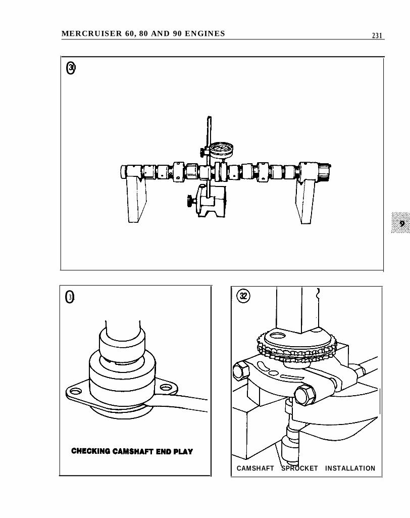
2. Measure the camshaft journal diameters with amicrometer (Figure 29). If any journal exceeds0.001 in. out-of-round, replace the camshaft.3. Suspend the camshaft between V-blocks andcheck for warpage with a dial indicator. See Figure30. Replace if reading is greater than 0.00 15 in.4. Check the distributor drive gear for excessivewear or damage.5. Check camshaft gear and thrust plate for wear ordamage. Insert a feeler gauge between the thrustplate and camshaft to measure end play. Figure 31shows the 80 camshaft; the 90 is similar but thethrust plate is at the sprocket end. If end playexceeds 0.005 in., remove the camshaft sprocket asdescribed in this chapter and replace the thrustplate and/or spacer as required. When thrustplate/spacer is replaced, recheck end play beforeinstalling camshaft.
Camshaft Sprocket Replacement
The camshaft sprocket is retained by a lockscrew on the MerCruiser 60 engine and pressedonto the camshaft on the 80 and 90 engines. Thisprocedure is for removing the sprocket on 80/90engines.1. Remove camshaft from engine as described inthis chapter.2. Support camshaft sprocket and press from theshaft.3. Installation is the reverse of removal. Supportcamshaft with a universal puller positioned underthe first bearing shoulder (Figure 32).4. Check end play as described in Step 5,Inspection in this chapter.
lon MERCRUISER 80DRIVE PINION INSTALLATION
IO28 MERCRUISER 80DRIVE PINION INSTALLATION I
MERCRUISER 60, 80 AND 90 ENGINES 231
0xl
031
CAMSHAFT SPROCKET INSTALLATION

232 CHAPTER NINE
OIL PAN
Removal/Installation
1. Remove the engine as described in this chapter.2. Place a 6-quart container under the oil pandrain plug. Remove the plug and let the crankcasedrain.
NOTEA modljication kit is available from marinedealers to assist in draining the oil when theengine is in the boat. This kit can be installed onany engine oil pan when the engine is removedfor service.
3. If mounted in an engine stand, rotate the engine180’ to place the oil pan in an upright position.4. Remove the oil pan attaching screws. Removethe oil pan and discard the gasket.5. Installation is the reverse of removal. Use a newgasket and tighten pan screws to specifications(Table 2).
Inspection
1. Remove all gasket residue from the oil panflanges and crankcase side rails with degreaser anda putty knife.2. Clean the pan thoroughly in solvent.3. Check the pan for dents or warped gasketsurfaces. Straighten or replace the pan as necessary.
OIL PUMP
Removal/Installation
1. Remove the oil pan as described in this chapter.2. Remove the oil pump attaching bolts. Removethe oil pump and gasket from the engine block. OnMetCruiser 80 and 90 engines, remove pumprotors from block. See Figure 33.3. Installation is the reverse of removal. Tightenbolts to specifications (Table 2).
Disassembly/Assembly(MerCruiser 60)
Refer to Figure 34 for this procedure.1. Remove the cover screws, holding cover inplace. Separate cover from body carefully, aspressure regulator assembly is under compression.Regulator spring seat and ball should come out ascover is removed.
333
OIL PUMP ROTORS I
Oil pump rotors
2. Mark gear teeth to assure reassembly withidentical gear indexing and remove idler gear anddrive pinion with shaft from the body.3. Oil all parts thoroughly before reassembly.4. Assembly is the reverse of disassembly. Indexgear marks, install a new cover gasket and rotatepump drive shaft by hand to check for smoothoperation.
Disassembly/Assembly(MerCruiser 80 and 90)
Refer to Figure 35 for this procedure.1. Remove retaining cotter pin from pump bodyand carefully remove pressure relief valvecomponents.2. Straighten the tab washers on the pickup tubeattaching screws. Remove screws and separatepickup tube from pump body.3. Oil all parts thoroughly before reassembly.

MERCRUISER 60, 80 AND 90 ENGINES 233
MERCRUISER 60 OIL PUMP
iI 1. Cover
2. Idler gear
; 3. Drive pinion and shaft4. Regulator seat, ball and spring5. Puma bodv
MERCRUISER 80 AND SO OIL PUMP
0 35
2. Pickup tube and screen
4. 3. Cotter Pressure pin relief valve assembly5. Pumo drive shaft and rotors
4. Assembly is the reverse of disassembly. Indexgear marks, install a new cover gasket and rotatepump drive shaft by hand to check for smoothoperation.
Inspection
1. Clean all parts thoroughly in solvent. Brush theinside of the body and the pressure regulatorchamber to remove all dirt and metal particles. Drywith compressed air, if available.2. Check the pump body and cover for cracks orexcessive wear.3. Check the pressure regulator valve for a properfit.4. Check the drive gear shaft-to-body fit forexcessive looseness.5. Check the inside of the pump cover for wearthat could allow oil to leak around the ends of thegears.
234 CHAPTER NINE
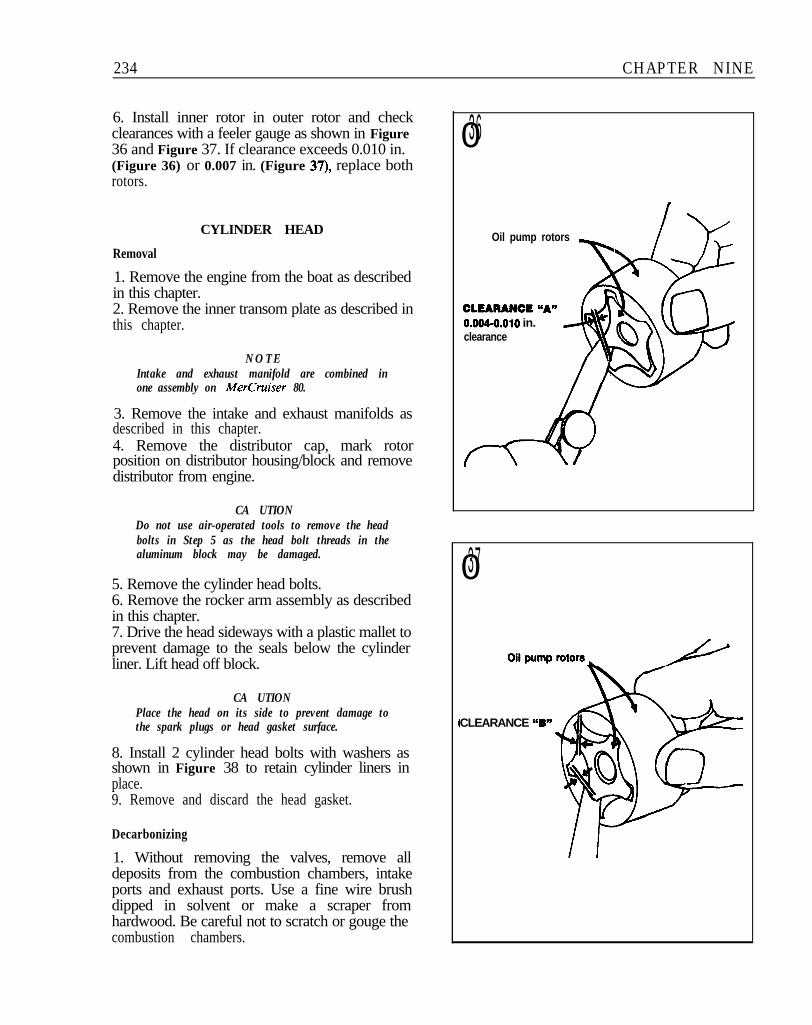
6. Install inner rotor in outer rotor and checkclearances with a feeler gauge as shown in Figure36 and Figure 37. If clearance exceeds 0.010 in.(Figure 36) or 0.007 in. (Figure 37), replace bothrotors.
CYLINDER HEAD
Removal
1. Remove the engine from the boat as describedin this chapter.2. Remove the inner transom plate as described inthis chapter.
NOTEIntake and exhaust manifold are combined inone assembly on MerCruiser 80.
3. Remove the intake and exhaust manifolds asdescribed in this chapter.4. Remove the distributor cap, mark rotorposition on distributor housing/block and removedistributor from engine.
CA UTIONDo not use air-operated tools to remove the headbolts in Step 5 as the head bolt threads in thealuminum block may be damaged.
5. Remove the cylinder head bolts.6. Remove the rocker arm assembly as describedin this chapter.7. Drive the head sideways with a plastic mallet toprevent damage to the seals below the cylinderliner. Lift head off block.
CA UTIONPlace the head on its side to prevent damage tothe spark plugs or head gasket surface.
8. Install 2 cylinder head bolts with washers asshown in Figure 38 to retain cylinder liners inplace.9. Remove and discard the head gasket.
Decarbonizing
1. Without removing the valves, remove alldeposits from the combustion chambers, intakeports and exhaust ports. Use a fine wire brushdipped in solvent or make a scraper fromhardwood. Be careful not to scratch or gouge thecombustion chambers.
036
Oil pump rotors
TCLEARANCE @‘A”O.QQ#.QlQ in.clearance
037
CLEARANCE “B”

MERCRUISER 60, 80 AND 90 ENGINES 235
CYLINDER LINER RETAINER BOLTS
MERCRUISER 80 AND 90 HEADGASKET POSITION
2. After all carbon is removed from thecombustion chambers and ports, clean the entirehead in solvent.3. Clean away all carbon on the piston tops. Donot remove the carbon ridge at the top of thecylinder bore.4. Remove the valves as described in this chapter.5. Clean the pushrod guides, valve guide bores andall bolt holes. Use a cleaning solvent to remove dirtand grease.6. Clean the valves with a fine wire brush orbuffing wheel.
Inspection
1. Check the cylinder head for signs of oil or waterleaks before cleaning.2. Clean the cylinder head thoroughly in solvent.While cleaning, look for cracks or other visiblesigns of damage, especially in the exhaust port andcombustion chamber areas. Look for corrosion orforeign material in the oil and water passages.Clean the passages with a stiff spiral brush, thenblow them out with compressed air.3. Check the cylinder head studs for damage andreplace, if necessary.4. Check the threaded rocker bolt holes fordamaged threads. Replace if necessary.5. Have any spark plug hole threads that arestripped repaired by a machine shop using a 14mm heli-coil insert.
Installation
1. Make sure the cylinder head and block gasketsurfaces and bolt holes are clean. Dirt in the blockbolt holes or on the head bolt threads will affecttightening torque.2. Recheck all visible oil and water passages forcleanliness.3. Remove liner retaining bolts and washers.4. Install a new head gasket. The beaded edge mustface the cylinder block.5A. MerCruiser 80-install head positioning toolpart No. C-91-46956 in the location shown inFigure 39.5B. MerCruiser 90-install head positioning toolpart No. C-91-58595 in the location shown inFigure 39.
NOTEThe MerCruiser 60 engine does not require ahead positioning tool.

236 CHAPTER NINE
6. MetCruiser 80 and 90-install rubber gasketaround camshaft recess in block. Do not overlaphead gasket at either end.7. Install cylinder head to block and align withlocating tool.
CA UTIONDo not use air-operated tools to install the headbolts in Step 8 as the head bolt threads in thealuminum block may be damaged.
8. Install head bolts and tighten to specificationsfollowing the sequence shown in Figure 409. Install rocker arm assembly as described in thischapter.10. Adjust valve clearance as described in thischapter.
NOTERetorque cylinder head bolts after runningengine.
11. Reverse Steps 1-4 of Removal to completeinstallation.
VALVES AND VALVE SEATS
Some of the following procedures must be doneby a dealer or machine shop, since they requirespecial knowledge and expensive machine tools.Others, while possible for the home mechanic, aredifficult or time-consuming. A general practiceamong those who do their own service is to removethe cylinder head, perform all disassembly exceptvalve removal, then take the head to a machineshop for inspection and service. Since the cost islow relative to the required effort and equipment,
040
0 41VALVE COMPONENTS
(MERCRUISER 60)
l-pd2- Q 0
1. Key locks2 . Spring 3-c a p3 . Spring4 . Base shim5 . Valve 4-o
5- L
0 42 VALVE COMPONENTS(MERCRUISER 80 AND SO)
1. Key locks2. Spring cap3. Spring4. Base shim5. Valve

MERCRUISER 60, 80 AND 90 ENGINES 237
043Exhaust Intake
VALVE REMOVAL
this is usually the best approach, even forexperienced mechanics. The following proceduresare given to acquaint the home mechanic withwhat the dealer or machine shop will do.
Valve Removal
Refer to Figure 41 or 42 for this procedure.1. Remove the cylinder head as described in thischapter.2. Remove the rocker arm assemblies as describedin this chapter.
NOTED@erent valve keys are used on intake andexhaust valves (Figure 43). Keep them separateas removed for proper reinstallation.
3. Compress the valve spring with a compressortool like the one shown in Figure 44. Remove thevalve keys and release the spring tension.4. Remove the valve spring cap, spring and basewashers.
CA UTIONRemove any burrs from the valve stem lockgrooves before removing the valves or the valveguides will be damaged.
5. Remove the valve and repeat Step 3 and Step 4on each remaining valve.6. Arrange the parts in order so they can bereturned to their original positions whenreassembled.7. Remove the valve tappets.
Inspection
1. Clean the valves with a fine wire brush orbuffing wheel. Discard any cracked, warped orburned valves.2. Measure valve stems at the top, center andbottom for wear. A machine shop can do this whenthe valves are ground. Also measure the length ofeach valve and the diameter of each valve head.
NOTECheck the thickness of the valve edge or marginafter the valves have been ground. See Figure 45.Any valve with a margin of less than IN2 in.should be discarded.
3. Remove all carbon and varnish from the valveguides with a stiff spiral wire brush.

238 CHAPTER NINE
NOTEThe next step assumes that all valve stems havebeen measured and are within specifications.Replace valves with worn stems beforeperforming this step.
4. Insert each valve into the guide from which itwas removed. Holding the valve just slightly off itsseat, rock it back and forth in a direction parallelwith the rocker arms. This is the direction in whichthe greatest wear normally occurs. If the valve stemrocks more than slightly, the valve guide isprobably worn.5. If there is any doubt about valve guidecondition after performing Step 4, have the valveguide measured with a valve stem clearancechecking tool. Compare the results to specifications(Table 1). Worn guides must be reamed for thenext oversize valve stem.6. Test the valve springs under load on a springtester (Figure 46). Replace any weak springs.7. Check each spring on a flat surface with a steelsquare. See Figure 47. Slowly revolve spring 360and note the space between the top of the coil andthe square. If it exceeds 5/16 in. at any point,replace the spring.8. Inspect the valve seat inserts. If worn or burned,they must be reconditioned. This is a job for adealer or machine shop, although the procedure isdescribed in this chapter.
Valve Guide Reaming
Worn valve guides must be reamed to accept avalve with an oversize stem. Reaming must bedone by hand (Figure 48) and is a job best left to anexperienced machine shop. The valve seat must berefaced after the guide has been reamed.
Valve Seat Reconditioning
1. Cut the valve seats to the specified angle (Table1) with a dressing stone. Remove only enoughmetal to obtain a good finish.2. Use tapered stones to obtain the specified seatwidth when necessary.3. Coat the corresponding valve face with Prussianblue dye.4. Insert the valve into the valve guide.5. Apply light pressure to the valve and rotate itapproximately l/4 turn.6. Lift the valve out. If it seats properly, the dyewill transfer evenly to the valve face.
046
MERCRUISER 60, 80 AND 90 ENGINES 239
0 49
\8 EXH ’ 4IN1
0 IN10 3E X H
8 EXH 2IN1
0 INT0 1EXH
/
MERCRUISER 60 AND 80
0 50
@2@
@l@
L J
MERCRUISER 90
7. If the dye transfers to the top of the valve face,lower the seat. If it transfers to the bottom of thevalve face, raise the seat.
Valve Installation
NOTEInstall all parts in the same positions from whichthey were removed.
1. Coat the valves with oil. Install the No. 1cylinder exhaust valve in the head.
NOTEInstall valve springs with closed coil end facingcylinder head in Step 2.
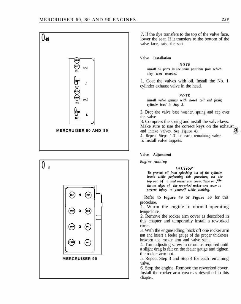
2. Drop the valve base washer, spring and cap overthe valve.3. Compress the spring and install the valve keys.Make sure to use the correct keys on the exhaustand intake valves. See Figure 43. .rpt‘; s4. Repeat Steps 1-3 for each remaining valve.5. Install valve tappets.
Valve Adjustment
Engine running
CA UTIONTo prevent oil from splashing out of the cylinderheads while performing this procedure, cut thetop out of a used rocker arm cover. Tape or Jilethe cut edges of the reworked rocker arm cover toprevent injury to yourself while working.
Refer to Figure 49 or Figure 50 for thisprocedure.1. Warm the engine to normal operatingtemperature.2. Remove the rocker arm cover as described inthis chapter and temporarily install a reworkedcover.3. With the engine idling, back off one rocker armnut and insert a feeler gauge of the proper thicknessbetween the rocker arm and valve stem.4. Turn adjusting screw in or out as required untila slight drag is felt on the feeler gauge and tightenthe rocker arm nut.5. Repeat Step 3 and Step 4 for each remainingvalve.6. Stop the engine. Remove the reworked cover.Install the rocker arm cover as described in thischapter.

240 CHAPTER NINE
Engine Stopped
Refer to Figure 49 or Figure 50 for thisprocedure.
1. Remove the valve cover as described in thischapter.2. Rotate the crankshaft until the No. 1 exhaustvalve is open and adjust No. 3 intake and No. 4exhaust valves. Back off rocker arm nut, insert afeeler gauge of the proper thickness between therocker arm and valve stem and turn adjustingscrew in or out until a slight drag is felt on thefeeler gauge. Tighten the rocker arm nut.3. Rotate crankshaft until No. 3 exhaust valve isopen and adjust No. 4 intake and No. 2 exhaustvalves.4. Rotate crankshaft until the No. 4 exhaust valveis open and adjust No. 2 intake and No. 1 exhaustvalves.5. Rotate crankshaft until the No. 2 exhaust valveis open and adjust No. 1 intake and No. 3 exhaustvalves.6. Install rocker arm cover as described in thischapter.7. Start the engine and warm to normal operatingtemperature. Shut engine off and recheck valve
051
MERCRUISER 60, 80 AND 90 ENGINES 241
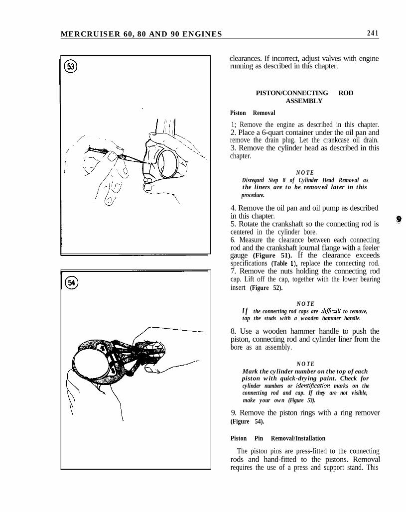
clearances. If incorrect, adjust valves with enginerunning as described in this chapter.
PISTON/CONNECTING RODASSEMBLY
Piston Removal
1; Remove the engine as described in this chapter.2. Place a 6-quart container under the oil pan andremove the drain plug. Let the crankcase oil drain.3. Remove the cylinder head as described in thischapter.
NOTEDisregard Step 8 of Cylinder Head Removal asthe liners are to be removed later in thisprocedure.
4. Remove the oil pan and oil pump as describedin this chapter.5. Rotate the crankshaft so the connecting rod iscentered in the cylinder bore.6. Measure the clearance between each connectingrod and the crankshaft journal flange with a feelergauge (Figure 51). If the clearance exceedsspecifications (Table l), replace the connecting rod.7. Remove the nuts holding the connecting rodcap. Lift off the cap, together with the lower bearinginsert (Figure 52).
NOTEIf the connecting rod caps are dijicult to remove,tap the studs with a wooden hammer handle.
8. Use a wooden hammer handle to push thepiston, connecting rod and cylinder liner from thebore as an assembly.
NOTEMark the cylinder number on the top of eachpiston with quick-drying paint. Check forcylinder numbers or ident&ation marks on theconnecting rod and cap. If they are not visible,make your own (Figure 53).
9. Remove the piston rings with a ring remover(Figure 54).
Piston Pin Removal/Installation
The piston pins are press-fitted to the connectingrods and hand-fitted to the pistons. Removalrequires the use of a press and support stand. This

242 CHAPTER NINE
is a job for a dealer or machine shop equipped to fitthe pistons to the pin, ream the pin bushings to thecorrect diameter and install the pistons and pins onthe connecting rods.
Piston Clearance Check
Unless you have precision’measuring equipmentand know how to use it properly, have thisprocedure done by a machine shop.1. Measure the piston diameter with a micrometer(Figure 55). Measure just below the rings at rightangles to the piston pin bore.2. Measure the cylinder liner diameter with a boregauge (Figure 56). Measure at the top, center andbottom of the liner bore, in front-to-rear andside-to-side directions.3. Subtract the piston diameter from the largestcylinder liner bore reading. If the difference exceedsspecifications (Table l), replace the liner.
Piston Ring Fit/Installation
1. Check the ring gap of each piston ring. To dothis, position the ring at the bottom of the ringtravel area in the liner and square it by tappinggently with an inverted piston. See Figure 57.
N O T EIf the cylinder liners have not been honed orreplaced, check the gap at the bottom of the ringtravel, where the liner is least worn.
2. Check the side clearance of the compressionrings as shown in Figure 58. Place the feeler gauge
05 7
Cylinderblock
sur face

MERCRUISER 60, 80 AND 90 ENGINES 243
alongside the ring all the way into the groove. If themeasurement is not within specifications (Table l),either the rings or ring grooves are worn. Inspectand replace as necessary.3. Using a ring expander tool (Figure 59), carefullyinstall the oil control ring, then the compressionrings.4. Position the ring gaps at 120” to each other.
Connecting Rod Inspection
Have the connecting rods checked forstraightness by a dealer or machine shop.Connecting rods can spring out of alignment duringshipping or handling. When installing newconnecting rods, have them checked formisalignment before installing the piston andpiston pin.
Connecting Rod BearingClearance Measurement
1. Place the connecting rods and upper bearinghalves on the proper connecting rod journals.2. Cut a piece of Plastigage the width of thebearing (Figure 60). Place the Plastigage on thejournal, then install the lower bearing half and cap.
NOTEDo not place Plastigage over the journal oilhole.
3. Tighten the connecting rod cap to specifications(Table 2). Do not rotate the crankshaft while thePlastigage is in place.4. Remove the connecting rod cap. Bearingclearance is determined by comparing the width ofthe flattened Plastigage to the markings on theenvelope. See Figure 61. If the clearance isexcessive, the crankshaft must be reground andundersize bearings installed.

244 CHAPTER NINE
Installing Piston/ConnectingRod Assemblies
1. Make sure the pistons are correctly installed onthe connecting rods. The arrow on the piston mustface up and the number on the connecting rod largeend must face to the right-hapd side.2. Make sure the ring gaps are positioned at 120’ toeach other.3. Immerse the entire piston in clean engine oil.Coat the cylinder liner wall with oil.4. Install piston and connecting rod assemblythrough the bottom of its cylinder liner with a ringcompressor tool.5. Install new bottom seals on the liner and set itinto the block with the arrow on the piston topfacing the flywheel end.6. Depress liner and hold. Check liner height witha straightedge and flat feeler gauge as shown inFigure 62. If liner height is not within specifications(Table l), remove the bottom seal and install oneof a thickness that will bring the height intospecifications.7. Take 2 height measurements at 180” intervals. Ifthe difference in readings exceeds 0.001 in., rotatethe liner 180” and remeasure.8. Install liner retaining washers and bolts (Figure63).9. Clean the connecting rod bearings carefully,including the back sides. Coat the journals andbearings with clean engine oil. Place the bearings inthe connecting rod and cap.10. Install the connecting rod cap. Use new locktabs under the cap nuts and tighten nuts tospecifications (Table 2).11. Check the connecting rod big-end play asdescribed under Piston Removal.
CRANKSHAFT
End Play Measurement
1. Pry the crankshaft to the rear of the engine witha large screwdriver.2. Install a dial indicator as shown in Figure 64with its plunger end resting against the crankshaftflange parallel to the crankshaft axis.3. Zero the dial indicator and force the crankshaftforward as far as it will go. Read the indicator andcompare to specifications (Table 1).
NOTEThrust washers are available in 3 thicknesses:0.091 in., 0.094 in. and 0.096 in.
062
CYLINDER LINER INSTALLATION
bolts and washers
063

MERCRUISER 60, 80 AND 90 ENGINES 2 4 5
064CRANKSHAFT END PLAY CHECK
065THRUST WASHER LOCATION
,.d
4. If end play is excessive, replace the thrustwashers with ones that will bring it intospecifications. If less than specified, check thethrust washer faces for imperfections.
Removal
1. Remove the engine as described in this chapter.2. Drain the crankcase oil and engine coolant. SeeChapter Four.3. Remove the flywheel and inner transom plate asdescribed in this chapter.4. Mount the engine on an engine stand, ifavailable.5. Invert the engine to bring the oil pan to anupright position.6. Remove the oil pan and oil pump as describedin this chapter.7. Remove the front cover as described in thischapter.8. Remove the crankshaft sprocket as described inthis chapter. ,;s,9. Rotate the crankshaft to position oneconnecting rod at bottom of its stroke.10. Remove the connecting rod bearing cap andbearing.11. Repeat Step 9 and Step 10 for each piston/rodassembly.12. Unbolt and remove the main bearing caps withbearing inserts.
N O T EIf the caps are dlficult to remove, lift the boltspartway out, then pry the caps from side to side.
13. Check the caps for identification numbers ormarks. If none are visible, clean the caps with awire brush. If marks still cannot be seen, makeyour own with quick-drying paint.14. Remove the thrust washers from the centermain bearing (Figure 65).15. Carefully lift the crankshaft from the engineblock. Lay the crankshaft, main bearings andbearing caps in order on a clean workbench.16. Remove the main bearing oil seal from thecylinder block and rear bearing cap.
Inspection
1. Clean the crankshaft thoroughly with solvent.Blow out the oil passages with compressed air.2. Check the main and connecting rod journals forscratches, grooves, scoring or cracks. Check oil seal

246 CHAPTER NINE
surface for burrs, nicks or other sharp edges whichmight damage a seal during installation.
NOTEIf you do not have precision measuringequipment and know how to use it, have amachine shop perform Step 3.
3. Check all journals and crankpins againstspecifications for out-of-roundness and taper. Ifnecessary, have the crankshaft reground and installnew undersize bearings.4. Support crankshaft on V-blocks and checkrunout of front and rear intermediate journals witha dial indicator. If runout exceeds 0.002 in., replacethe crankshaft .
Main Bearing Clearance Measurement
Main bearing clearance is measured withPlastigage in the same manner as connecting rodbearing clearance, described in this chapter.Excessive clearance requires that the bearings bereplaced, the crankshaft be reground or both.
Installation
1. Install a new rear main bearing oil seal in thecylinder block and bearing cap grooves. Seal lipshould face inside of engine.2. Lubricate seal lip with clean engine oil. Makesure oil is kept away from the parting line surface.3. Install the main bearing inserts in the bores withtheir tangs engaging the slots provided in the block.4. Install the main bearing inserts in the bearingcaps.5. Carefully lower the crankshaft into position inthe block, then install the thrust washers as shownin Figure 65.6. Install main bearing caps and connecting rodcaps. Tighten cap bolts/nuts to specifications(Table 2).7. Measure crankshaft end play as described in thischapter.8. Reverse Steps 1-8 of Removal in this chapter.
FLYWHEEL
Removal/Installation(MerCruiser 60 Rear Flywheel)
1. Remove the engine as described in this chapter.2. Remove the inner transom plate as described inthis chapter.
3. Remove the flywheel housing.4. Remove the flywheel nuts. Slide coupler andflywheel off crankshaft studs.5. Installation is the reverse of removal. Use newelastic stop nuts and tighten securely.
Removal/Installation(MerCruiser 60 Front Flywheel/Alternator)
1. Remove screw and washer holding alternatorflywheel to crankshaft.2. Install puller part No. C-91-38835Al orequivalent and remove flywheel (Figure 66).3. Remove alternator stator (Figure 67).

MERCRUISER 60, 80 AND 90 ENGINES 247
4. Installation is the reverse of removal. Wipefront cover with a thin coat of grease beforeinstalling flywheel.
Removal/Installation(MerCkher 80 and 90)1. Remove the engine as described in this chapter.2. Remove the inner transom plate as described inthis chapter.3. Insert a socket with extension through thecoupler splines and remove the coupler stop nut.4. Remove the flywheel cover and housing withalternator stator.
5. Remove the elastic stop nuts holding thealternator rotor to the flywheel (Figure 68). Slidethe flywheel and rotor off the crankshaft studs.6. Installation is the reverse of removal. Use newelastic stop nuts and tighten to specifications(Table 2).
Inspection1. Visually check the flywheel surfaces for cracks,deep scoring, excessive wear, heat discolorationand checking.2. Inspect the ring gear teeth for cracks, brokenteeth or excessive wear. If severely worn, check thestarter motor drive teeth for similar wear ordamage. Replace as indicated.3. Lubricate engine coupling splines withMultipurpose Lubricant (part No. C-92-63250). Ifboat is used mainly for trolling, use Universal JointLubricant (part No. C-92-74058Al) for betterresults.
CYLINDER BLOCK
Cleaning and Inspection1. Clean the block thoroughly with solvent.Remove any gasket residue from the machinedsurfaces. Check all core plugs for leaks and replaceany that are suspect. See Core Plugs in this chapter.Remove any plugs that seal oil passages. Check oiland coolant passages for sludge, dirt and corrosionwhile cleaning. If the passages are very dirty, havethe block boiled out by a machine shop. Blow outall passages with compressed air. Check the threadsin the head bolt holes to be sure they are clean. Ifdirty, use a tap to true up the threads and removeany deposits.2. Examine the block for cracks. To confirmsuspicions about possible leak areas, use a mixtureof one part kerosene and 3 parts engine oil. Coatthe suspected area with this solution, then wipe dryand immediately apply a solution of zinc oxidedissolved in wood alcohol. If any discolorationappears in the treated area, the block is cracked andshould be replaced.3. Check flatness of the cylinder block deck withliners removed. Place an accurate straightedge onthe block. If there is any gap between the block andstraightedge, measure it with a feeler gauge.Measure from end to end and from corner tocorner, as shown in Figure 69. If distortion exceeds0.002 in., have the block resurfaced by a machineshop or dealer.

248 CHAPTER NINE
4. Measure the cylinder liner bores with a bore 1. Tap the bottom edge of the core plug with agauge (Figure 70) as described in Step 2, Piston hammer and drift. Use several sharp blows to pushClearance Check in this chapter. If the liner bores the bottom of the plug inward, tilting the top outexceed maximum tolerances, they must be (Figure 71).replaced. Replacement is also necessary if the liner 2. Grip the top of the plug with pliers. Pull the plugwalls are badly scuffed or scored. Light scuffing or from its bore (Figure 72) and discard.scoring can be corrected by having the liners honed 3. Clean the plug bore thoroughly to remove allby a machine shop or dealer. traces of the old sealer.
CORE PLUGS
Check the condition of all core plugs in the blockand cylinder head whenever the engine is out of theboat for service. If any signs of leakage or corrosionare found around one plug, replace them all.
Removal/Installation
CA UTIONDo not drive core plugs into the engine casting. Itwill be impossible to retrieve them and they canrestrict coolant circulation, resulting in seriousengine damage.
5-. -__--_ -.-.. ___
4. Apply a light coat of Loctite Stud N’ Bearingmount or equivalent to the plug bore.5. Install the new core plug with an appropriatesize driver or socket. The sharp edge of the plugshould be at least 0.02 in. inside the lead-inchamfer.
071
Strike here with hammer
L&I
Remove plug
n

MERCRUISER 60,80 AND 90 ENGINES 249
Table 1 ENGINE SPECIFICATIONS
bveDisplacementModel 60Model 60Model 90
Cylinder numbering (tront’to rear)Firing order
Cylinder linerDiameterModel 60Model 60Model 90
Height above blockModel 60Model 60,90
Out-of-roundTaper
Piston clearance
Piston ringsGroove clearancelop compression2nd compressionO i l
Piston pinDiameterModel 60Model 60,90
ClearanceFit in rod
CrankshaftMain journal diameter
Model 60Model 60,90
Main journal taperMain journal out-of-roundMain bearing clearanceModel 60Model 60,90
End playModel 60Model 60,90
Crankpin diameterModel 60Model 60,90
Crankpin taperCrankpin out-of-round
Nine 4-cylinder
67.56 cid69.70 cid95.50 cidl-2-3-4l-3-4-2
2.7461-2.7569 in.2.9921-3.0031 in.3.0315-3.0426 in.
0.003-0.005 in.0.006-0.006 in.0.002 in. max.0.005 in. max.
0.0035 in. max.
0.0015-0.0035 in.0.0015-0.0035 in.0.001-0.006 in.
0.7067 in.0.7674 in.0.0035 in. max.interference
1.6110 in.2.125 in.0.001 in. max.0.001 in. max.
0.001-0.003 in.0.0015-0.0031 in.
0.0016-0.0075 in.0.0016-0.0091 in.
1.731 in.1.6696 in.0.001 in. max.0.001 in. max.
(continued)

250 CHAPTER NINE
Table 1 ENGINE SPECIFICATIONS (continued)
onnecting rod3earing clearanceModel 60Model 60,90
Side clearanceamshaftIntake lobe liftModel 60Model 60Model 90
Exhaust lobe liftModel 60Model 60Model 90
Journal diameterModel 60Model 60,90
End playModel 60Model 60,90
Runout‘alvesLifterLashModel 60
IntakeExhaust
Model 60,90IntakeExhaust
Face angleSeat angleSeat runoutSeat width
IntakeModel 60Model 60Model 90
ExhaustModel 60Model 60Model 90
Stem-to-guide clearanceIntakeExhaust
ralve springsFree lengthModel 60Model 60Model 90
Damper free lengthModel 60Model 90
Approximate No. of coilsModel 60Model 90
0.001-0.003 in.0.0015-0.0031 in.0.004-0.010 in.
0.2059 in.0.1979 in.0.1979 in.
0.2109 in.0.1595 in.0.1979 in.
1.4961 in.1.6535 in.
0.0016-0.0075 in.0.002-0.0045 in.0.0015 in. max.
Mechanical
0.005 in.0.006 in.
0.006 in.0.010 in.45”46”0.002 in. max.
0.055 in.0.099 in.0.067 in.
0.067 in.0.096 in.0.067 in.
0.001-0.003 in.0.0015-0.0045 in.
1.65 in.1.690 in.2.127 in.
1.52 in.1.614 in.
55
-. --

MERCRUISER 60, 80 AND 90 ENGINES 251
Table 2 TIGHTENING TORQUES
Fastener
Alternator flywheelCamshaftSprocketThrust plateCover plate
Crankshaft sprocketConnecting rod cap nutsCoupling-to-flywheelCylinder headDistributor hold-down clampExhaust manifold elbowF u e l p u m pFlywhee lFlywheel housing-to-blockFront coverMain bearing capManifold-to-headOil pan (side)Oil pan drain plugOil pumpCoverPickupTo block
Rocker arm coverRocker shaft supportRocker shaftSpark plugsliming chainTensionerGuide
ft.=lb.Model 60 Model 8 0 a n d 9 0
35
14.561 550
2 1 3325 3343 5013 6
813 1 4
3433 38
943 4515 1 5
718
15156-1331 813
13 21’
79
l Tapered plugs without gaskets, 15 ft.-lb.