Mercedes Sprinter 5 Manual valve · mercedes sprinter 5 series – chassis cab issue v1 –...
25
MERCEDES SPRINTER 5 SERIES – CHASSIS CAB Issue v1 – 23/07/08 Glide-Rite ® Air Suspension Installation Manual Mercedes Sprinter 5 Series Chassis Cab Glide-Rite ® Products Ltd Mill Lane Works Passfield Liphook Hampshire GU30 7RP Tel: +44 (0) 1428 751711 Fax: +44 (0) 1428 751677 Email: [email protected] Web: www.glide-rite.com
-
Upload
duongkhanh -
Category
Documents
-
view
232 -
download
0
Transcript of Mercedes Sprinter 5 Manual valve · mercedes sprinter 5 series – chassis cab issue v1 –...

MERCEDES SPRINTER 5 SERIES – CHASSIS CAB
Issue v1 – 23/07/08
Glide-Rite® Air Suspension
Installation Manual
Mercedes Sprinter 5 Series
Chassis Cab
Glide-Rite® Products Ltd
Mill Lane Works
Passfield
Liphook
Hampshire
GU30 7RP
Tel: +44 (0) 1428 751711
Fax: +44 (0) 1428 751677
Email: [email protected]
Web: www.glide-rite.com
MERCEDES SPRINTER 5 SERIES – CHASSIS CAB
Issue v1 – 23/07/08
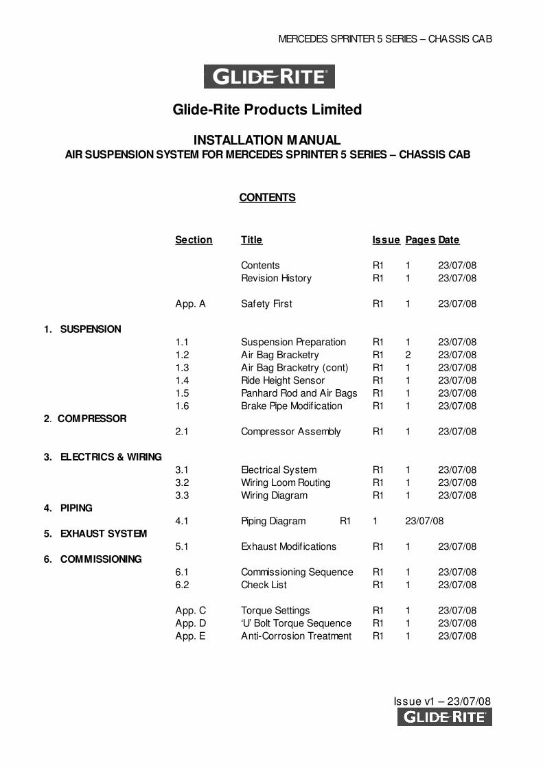
Glide-Rite Products Limited
INSTALLATION MANUAL AIR SUSPENSION SYSTEM FOR MERCEDES SPRINTER 5 SERIES – CHASSIS CAB
CONTENTS
Section Title Issue Pages Date
Contents R1 1 23/07/08
Revision History R1 1 23/07/08
App. A Safety First R1 1 23/07/08
1. SUSPENSION
1.1 Suspension Preparation R1 1 23/07/08
1.2 Air Bag Bracketry R1 2 23/07/08
1.3 Air Bag Bracketry (cont) R1 1 23/07/08
1.4 Ride Height Sensor R1 1 23/07/08
1.5 Panhard Rod and Air Bags R1 1 23/07/08
1.6 Brake Pipe Modif ication R1 1 23/07/08
2. COMPRESSOR
2.1 Compressor Assembly R1 1 23/07/08
3. ELECTRICS & WIRING
3.1 Electrical System R1 1 23/07/08
3.2 Wiring Loom Routing R1 1 23/07/08
3.3 Wiring Diagram R1 1 23/07/08
4. PIPING
4.1 Piping Diagram R1 1 23/07/08
5. EXHAUST SYSTEM
5.1 Exhaust Modif ications R1 1 23/07/08
6. COMMISSIONING
6.1 Commissioning Sequence R1 1 23/07/08
6.2 Check List R1 1 23/07/08
App. C Torque Settings R1 1 23/07/08
App. D ‘U’ Bolt Torque Sequence R1 1 23/07/08
App. E Anti-Corrosion Treatment R1 1 23/07/08
MERCEDES SPRINTER 5 SERIES – CHASSIS CAB
Issue v1 – 23/07/08
Glide-Rite Products Limited
INSTALLATION MANUAL AIR SUSPENSION SYSTEM FOR MERCEDES SPRINTER 5 SERIES – CHASSIS CAB
REVISION HISTORY
Date Description
23/07/08 New Installation Manual - v1
Glide-Rite Products Limited
Document Control and Approval
This is a controlled document. Any amendment or revision to this document w ill be notif ied to the copy
holder, thereby ensuring that the document is maintained in a fully updated version at all times.
The approval of this document, in its latest revision, is given by:
Name: Mark Glazier Position: Technical Director Signed: ………………. Dated: 23/07/08
MERCEDES SPRINTER 5 SERIES – CHASSIS CAB
Issue v1 – 23/07/08
Appendix A SAFETY FIRST
Read and follow all warnings Never disregard w arning instructions: follow them at all times. Read and follow the instructions
printed on labels or signs f ixed to the vehicle, components or containers.
Support vehicle securely Never carry out any w ork under the vehicle unless it is raised and securely supported on a
properly rated garage lif t or jack and axle stands.
Always work safely Never tamper w ith brake lines, fuel pipes or electrical w iring unless instructed to do so.
Disconnect the battery before starting w ork on any vehicle. Alw ays follow the vehicle manufacturer’s service instructions w hen carrying out w ork on a
vehicle. Alw ays w ork in a clean, tidy and methodical manner.
Seek help w ith heavy items Do not lif t heavy items unaided - alw ays seek assistance.
Be aw are of the limits set out in the Manual Handling Regulations.
Fuel is dangerous if handled carelessly Never allow fuel tanks or lines to be exposed to sparks, heat or w eld spatter.
Diesel is FLAMMABLE. Petrol is HIGHLY FLAMMABLE and its vapour is EXPLOSIVE. Drain fuel tanks and lines before starting w ork.
Alw ays w ork in a w ell ventilated area w hen dealing w ith fuels.
Wear protective clothing Tie back long hair and remove ties, loose clothing and jew ellery before using pow er tools. Wear
eye protection and steel toe-cap shoes. Use ear defenders if necessary. Use the correct shield and protective clothing w hen w elding. Avoid being ‘f lashed’.
Exhaust gas is dangerous Exhaust gas contains carbon monoxide w hich itself has no colour or odour.
Carbon monoxide can cause unconsciousness and can be lethal. Do not run engines in confined spaces such as garages unless an
exhaust extractor can be used.
High pressure can injure Drain air systems completely before disconnecting any part.
Electrical safety Disconnect battery before w orking on any electrical system. Never f it electrical parts or w ires
w here they could come into contact w ith fuel pipes or tanks. Check that pipes are not chafed or damaged by sharp edges on the vehicle.
If the vehicle is f itted w ith other non-standard electrical equipment (e.g. tail lif t), consult a qualif ied auto-electrician or contact the Glide-Rite Technical Helpline 01428 751711.
Brake Pipe Routing
Care must be taken to prevent damage to metal brake pipes during installation. Brake pipes and cables must all be routed in accordance w ith installation procedures and extra
care must be taken to ensure suff icient clearance around other components.

MERCEDES SPRINTER 5 SERIES – CHASSIS CAB
Issue v1 – 23/07/08
Wiring System
Electric w iring must not be routed to touch side w all of fuel tank. Wiring loom must not be aff ixed to any existing w iring supports or components.
MERCEDES SPRINTER 5 SERIES – CHASSIS CAB
Issue v1 – 23/07/08
1. SUSPENSION
1.1 SUSPENSION PREPARATION
1.1.1 If spare w heel carrier is f itted, remove w heel and storage bracket. Note:- For future
reference, w hen ordering from the factory the vehicle can be specif ied w ithout the spare
w heel and carrier by omitting factory code R65.
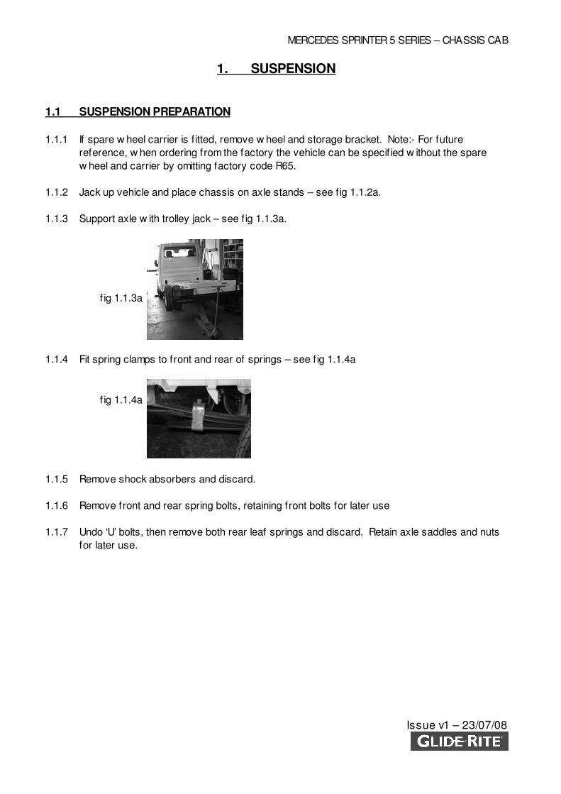
1.1.2 Jack up vehicle and place chassis on axle stands – see f ig 1.1.2a.
1.1.3 Support axle w ith trolley jack – see f ig 1.1.3a.
1.1.4 Fit spring clamps to front and rear of springs – see f ig 1.1.4a
1.1.5 Remove shock absorbers and discard.
1.1.6 Remove front and rear spring bolts, retaining front bolts for later use
1.1.7 Undo ‘U’ bolts, then remove both rear leaf springs and discard. Retain axle saddles and nuts
for later use.
f ig 1.1.3a
f ig 1.1.4a
MERCEDES SPRINTER 5 SERIES – CHASSIS CAB
Issue v1 – 23/07/08
1. SUSPENSION
1.2 AIR BAG BRACKETRY
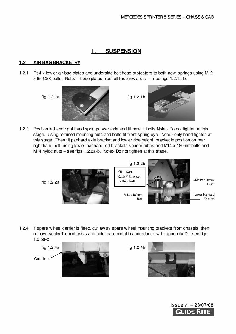
1.2.1 Fit 4 x low er air bag plates and underside bolt head protectors to both new springs using M12
x 65 CSK bolts. Note:- These plates must all face inw ards. – see f igs 1.2.1a-b.
1.2.2 Position left and right hand springs over axle and f it new U bolts Note:- Do not tighten at this
stage. Using retained mounting nuts and bolts f it front spring eye Note:- only hand tighten at
this stage. Then f it panhard axle bracket and low er ride height bracket in position on rear
right hand bolt using low er panhard rod brackets spacer tubes and M14 x 180mm bolts and
M14 nyloc nuts – see f igs 1.2.2a-b. Note:- Do not tighten at this stage.
1.2.4 If spare w heel carrier is f itted, cut aw ay spare w heel mounting brackets from chassis, then
remove sealer from chassis and paint bare metal in accordance w ith appendix D – see f igs
1.2.5a-b.
fig 1.2.1a
fig 1.2.2a
fig 1.2.4a fig 1.2.4b
fig 1.2.2b
M14 x 180mm
Bolt
M14 x 180mm
CSK
Lower Panhard
Bracket
Cut l ine
fig 1.2.1b
Fit lower
R/H/V bracket
to this bolt
MERCEDES SPRINTER 5 SERIES – CHASSIS CAB
Issue v1 – 23/07/08
1. SUSPENSION
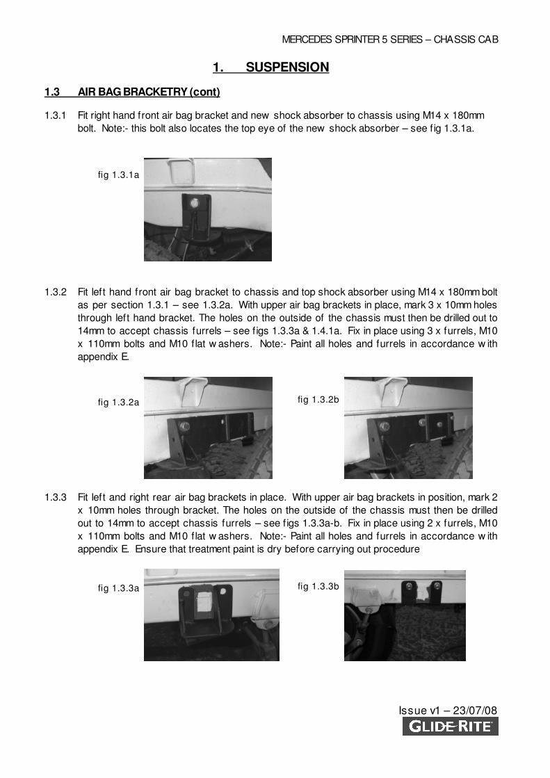
1.3 AIR BAG BRACKETRY (cont)
1.3.1 Fit right hand front air bag bracket and new shock absorber to chassis using M14 x 180mm
bolt. Note:- this bolt also locates the top eye of the new shock absorber – see f ig 1.3.1a.
1.3.2 Fit left hand front air bag bracket to chassis and top shock absorber using M14 x 180mm bolt
as per section 1.3.1 – see 1.3.2a. With upper air bag brackets in place, mark 3 x 10mm holes
through left hand bracket. The holes on the outside of the chassis must then be drilled out to
14mm to accept chassis furrels – see f igs 1.3.3a & 1.4.1a. Fix in place using 3 x furrels, M10
x 110mm bolts and M10 flat w ashers. Note:- Paint all holes and furrels in accordance w ith
appendix E.
1.3.3 Fit left and right rear air bag brackets in place. With upper air bag brackets in position, mark 2
x 10mm holes through bracket. The holes on the outside of the chassis must then be drilled
out to 14mm to accept chassis furrels – see f igs 1.3.3a-b. Fix in place using 2 x furrels, M10
x 110mm bolts and M10 flat w ashers. Note:- Paint all holes and furrels in accordance w ith
appendix E. Ensure that treatment paint is dry before carrying out procedure
fig 1.3.1a
fig 1.3.2a
fig 1.3.3a fig 1.3.3b
fig 1.3.2b
MERCEDES SPRINTER 5 SERIES – CHASSIS CAB
Issue v1 – 23/07/08
1. SUSPENSION
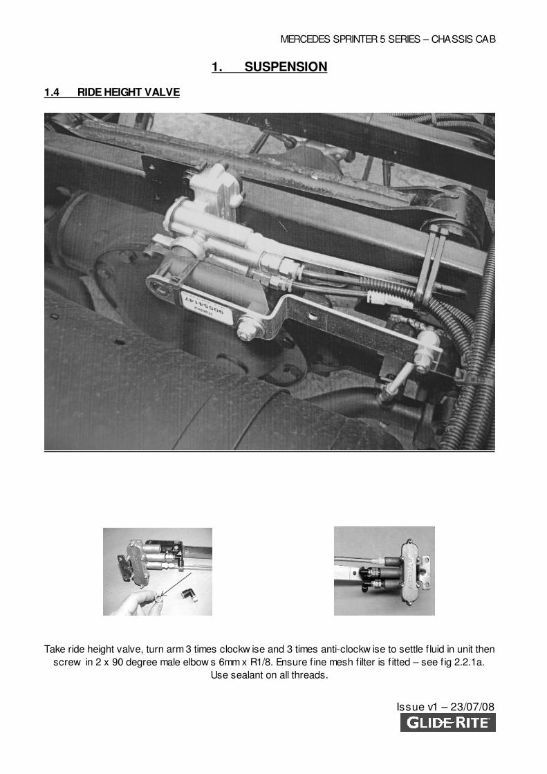
1.4 RIDE HEIGHT VALVE
Take ride height valve, turn arm 3 times clockw ise and 3 times anti-clockw ise to settle f luid in unit then
screw in 2 x 90 degree male elbow s 6mm x R1/8. Ensure f ine mesh f ilter is f itted – see f ig 2.2.1a.
Use sealant on all threads.
MERCEDES SPRINTER 5 SERIES – CHASSIS CAB
Issue v1 – 23/07/08
1. SUSPENSION
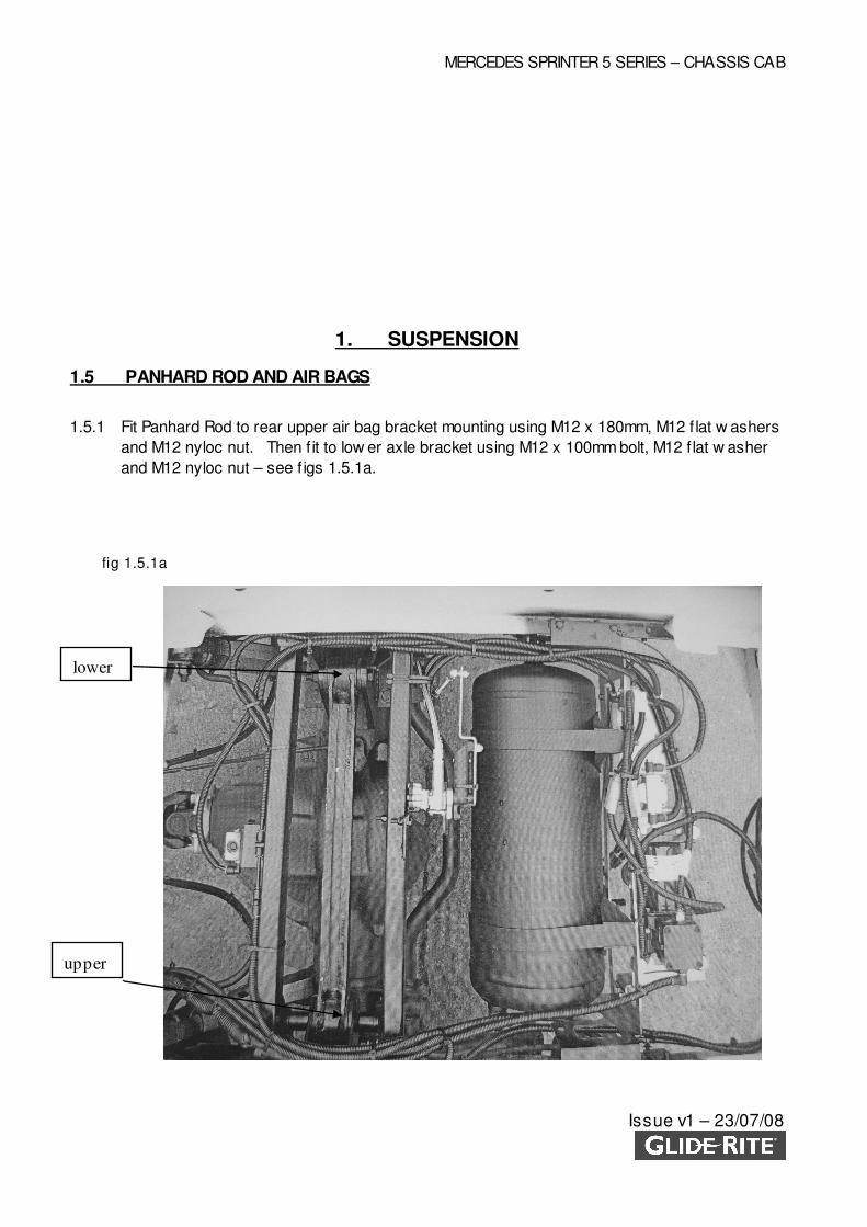
1.5 PANHARD ROD AND AIR BAGS
1.5.1 Fit Panhard Rod to rear upper air bag bracket mounting using M12 x 180mm, M12 flat w ashers
and M12 nyloc nut. Then f it to low er axle bracket using M12 x 100mm bolt, M12 f lat w asher
and M12 nyloc nut – see f igs 1.5.1a.
fig 1.5.1a
upper
lower
MERCEDES SPRINTER 5 SERIES – CHASSIS CAB
Issue v1 – 23/07/08
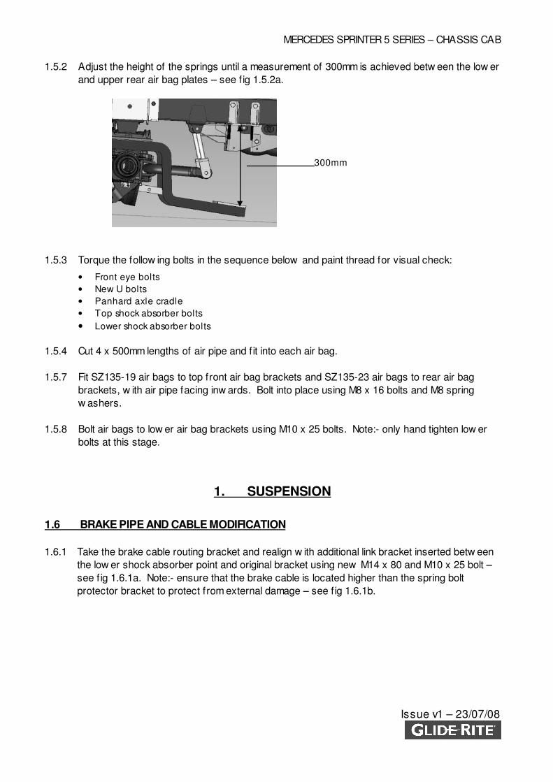
1.5.2 Adjust the height of the springs until a measurement of 300mm is achieved betw een the low er
and upper rear air bag plates – see f ig 1.5.2a.
1.5.3 Torque the follow ing bolts in the sequence below and paint thread for visual check:
• Front eye bolts
• New U bolts
• Panhard axle cradle
• Top shock absorber bolts
• Lower shock absorber bolts
1.5.4 Cut 4 x 500mm lengths of air pipe and f it into each air bag.
1.5.7 Fit SZ135-19 air bags to top front air bag brackets and SZ135-23 air bags to rear air bag
brackets, w ith air pipe facing inw ards. Bolt into place using M8 x 16 bolts and M8 spring
w ashers.
1.5.8 Bolt air bags to low er air bag brackets using M10 x 25 bolts. Note:- only hand tighten low er
bolts at this stage.
1. SUSPENSION
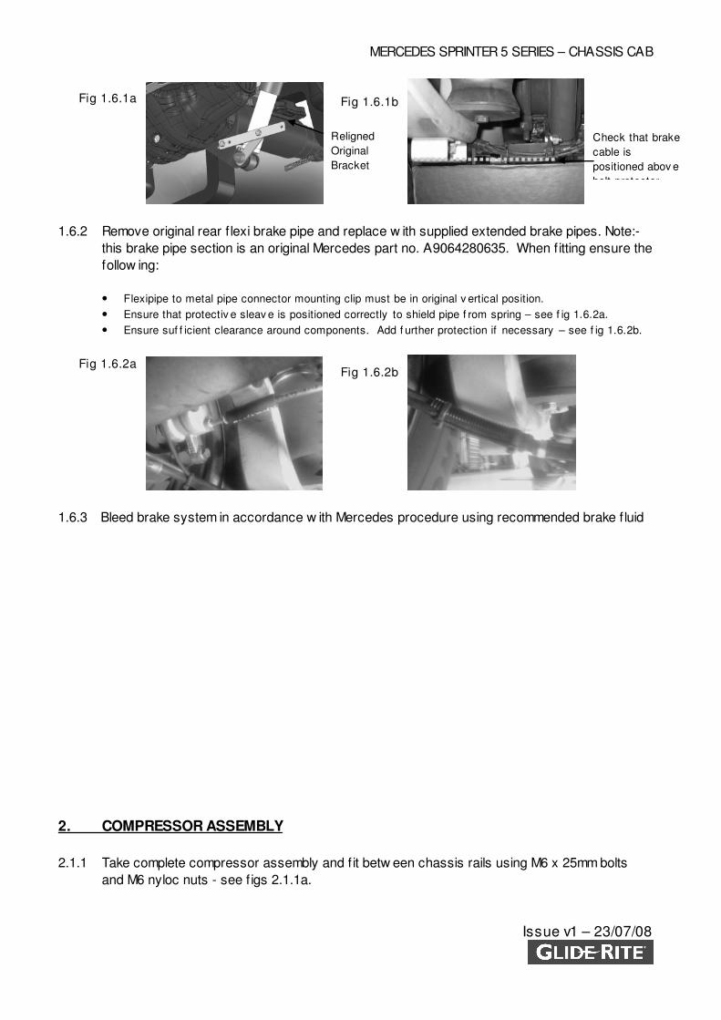
1.6 BRAKE PIPE AND CABLE MODIFICATION
1.6.1 Take the brake cable routing bracket and realign w ith additional link bracket inserted betw een
the low er shock absorber point and original bracket using new M14 x 80 and M10 x 25 bolt –
see f ig 1.6.1a. Note:- ensure that the brake cable is located higher than the spring bolt
protector bracket to protect from external damage – see f ig 1.6.1b.
300mm
MERCEDES SPRINTER 5 SERIES – CHASSIS CAB
Issue v1 – 23/07/08
1.6.2 Remove original rear f lexi brake pipe and replace w ith supplied extended brake pipes. Note:-
this brake pipe section is an original Mercedes part no. A9064280635. When f itting ensure the
follow ing:
• Flexipipe to metal pipe connector mounting clip must be in original v ertical position.
• Ensure that protectiv e sleav e is positioned correctly to shield pipe f rom spring – see f ig 1.6.2a.
• Ensure suf f icient clearance around components. Add f urther protection if necessary – see f ig 1.6.2b.
1.6.3 Bleed brake system in accordance w ith Mercedes procedure using recommended brake f luid
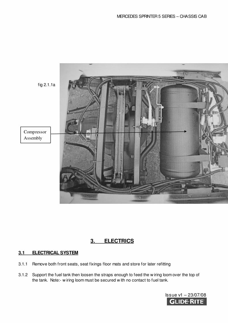
2. COMPRESSOR ASSEMBLY
2.1.1 Take complete compressor assembly and f it betw een chassis rails using M6 x 25mm bolts
and M6 nyloc nuts - see f igs 2.1.1a.
Religned
Original
Bracket
Fig 1.6.1a
Fig 1.6.2a Fig 1.6.2b
Check that brake
cable is
positioned abov e
bolt protector
Fig 1.6.1b
MERCEDES SPRINTER 5 SERIES – CHASSIS CAB
Issue v1 – 23/07/08
3. ELECTRICS
3.1 ELECTRICAL SYSTEM
3.1.1 Remove both front seats, seat f ixings f loor mats and store for later refitting
3.1.2 Support the fuel tank then loosen the straps enough to feed the w iring loom over the top of
the tank. Note:- w iring loom must be secured w ith no contact to fuel tank.
f ig 2.1.1a
Compressor
Assembly
MERCEDES SPRINTER 5 SERIES – CHASSIS CAB
Issue v1 – 23/07/08
3.1.3 Run the w iring loom and air intake pipe over the tank and up though the grommet in the vehicle
cab f loor.
3.1.4 Wiring loom must be fastened to chassis using supplied chassis clips. Note:- its very important
that the Glide-Rite w iring loom does not contact the fuel tank w hen in f inal routed position –
see routing diagram 3.2. Contact Glide-Rite if further information is required.
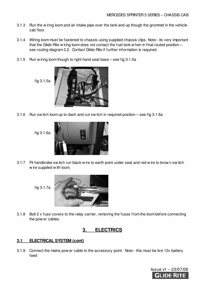
3.1.5 Run w iring loom though to right hand seat base – see f ig 3.1.5a
3.1.6 Run sw itch loom up to dash and cut sw itch in required position – see f ig 3.1.6a
3.1.7 Fit handbrake sw itch run black w ire to earth point under seat and red w ire to brow n sw itch
w ire supplied w ith loom.
3.1.8 Bolt 2 x fuse covers to the relay carrier, removing the fuses from the loom before connecting
the pow er cables.
3. ELECTRICS
3.1 ELECTRICAL SYSTEM (cont)
3.1.9 Connect the mains pow er cable to the accessory point. Note:- this must be live 12v battery
feed
f ig 3.1.5a
f ig 3.1.6a
f ig 3.1.7a
MERCEDES SPRINTER 5 SERIES – CHASSIS CAB
Issue v1 – 23/07/08
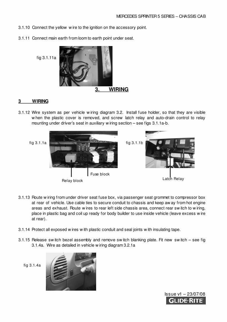
3.1.10 Connect the yellow w ire to the ignition on the accessory point.
3.1.11 Connect main earth from loom to earth point under seat.
3. WIRING
3 WIRING
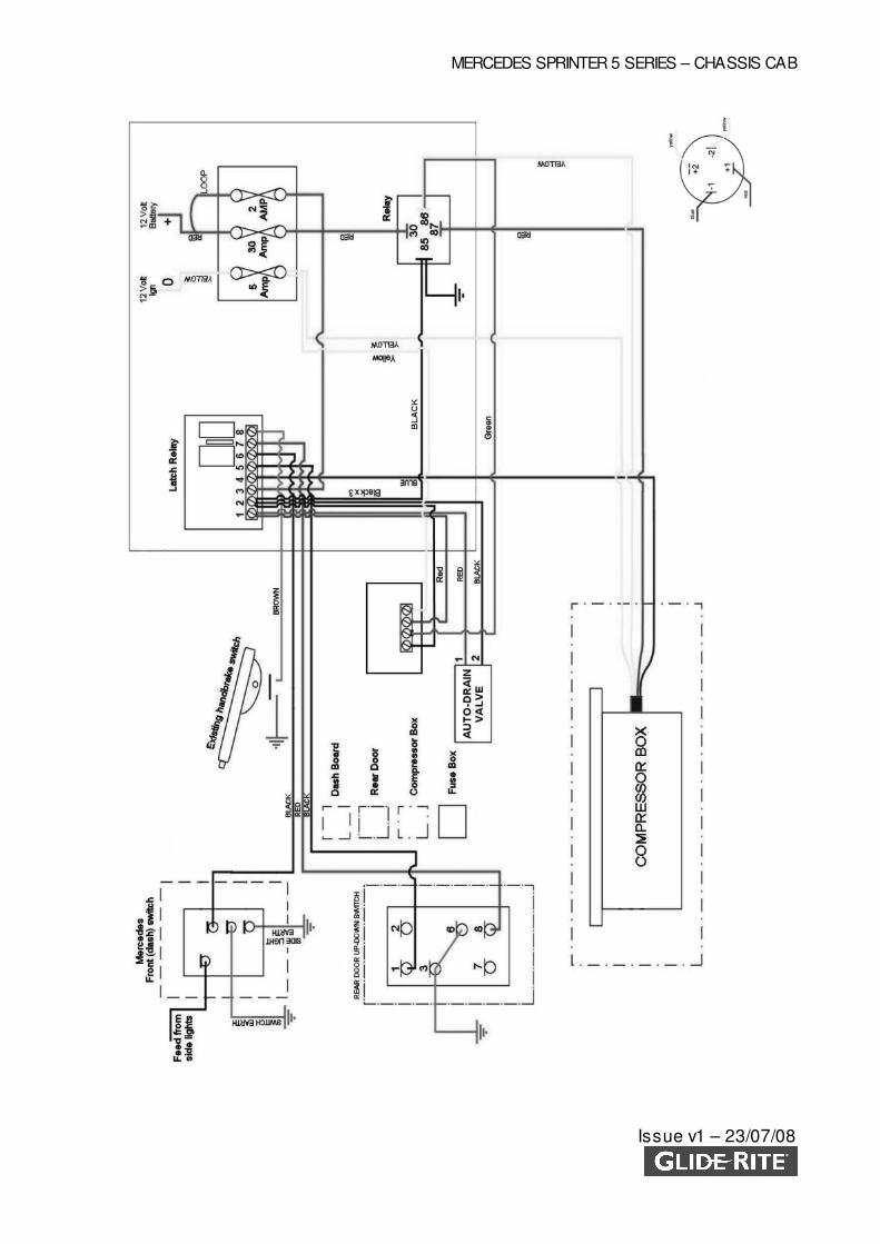
3.1.12 Wire system as per vehicle w iring diagram 3.2. Install fuse holder, so that they are visible
w hen the plastic cover is removed, and screw latch relay and auto-drain control to relay
mounting under driver’s seat in auxiliary w iring section – see f igs 3.1.1a-b.
3.1.13 Route w iring from under driver seat fuse box, via passenger seat grommet to compressor box
at rear of vehicle. Use cable ties to secure conduit to chassis and keep aw ay from hot engine
areas and exhaust. Route w ires to rear left side chassis area, connect rear sw itch to w iring,
place in plastic bag and coil up ready for body builder to use inside vehicle (leave excess w ire
at rear).
3.1.14 Protect all exposed w ires w ith plastic conduit and seal joints w ith insulating tape.
3.1.15 Release sw itch bezel assembly and remove sw itch blanking plate. Fit new sw itch – see f ig
3.1.4a. Wire as detailed in vehicle w iring diagram 3.2.1a
f ig 3.1.11a
fig 3.1.1a fig 3.1.1b
Fuse block
Relay block Latch Relay
fig 3.1.4a
MERCEDES SPRINTER 5 SERIES – CHASSIS CAB
Issue v1 – 23/07/08
Panel van version
Route wires inside rear door pillar and mount switch in suitable place.
3.1.16 Connect the to the valve block, pressure sw itch, compressor
3.1.17 Refit fuses
3.1.18 Refit loom covers and mats and front seats
3.1.19 Retighten fuel tank. Note:- do not trap loom or air intake pipe w hen tightening straps. Ensure
that w iring loom is routed clear of fuel tank.
WIRING DIAGRAM
MERCEDES SPRINTER 5 SERIES – CHASSIS CAB
Issue v1 – 23/07/08

MERCEDES SPRINTER 5 SERIES – CHASSIS CAB
Issue R1 – 23/07/08
4. PIPING
4.1 PIPING DIAGRAM
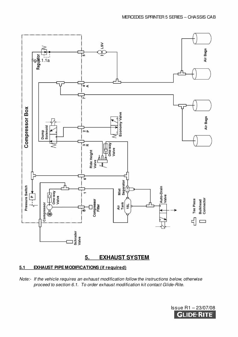
4.1.1 Pipe system as per piping diagram fig 4.1.1a. Use pipe cutters so that all cuts are square. All
air pipe should be protected w ith conduit, cable tied aw ay from ground and exhaust pipe. Pipe
MUST NOT be bent, allow ing only the natural curve of the pipe.
MERCEDES SPRINTER 5 SERIES – CHASSIS CAB
Issue R1 – 23/07/08
5. EXHAUST SYSTEM
5.1 EXHAUST PIPE MODIFICATIONS (if required)
Note:- If the vehicle requires an exhaust modification follow the instructions below, otherwise
proceed to section 6.1. To order exhaust modification kit contact Glide-Rite.
f ig 4.1.1a
MERCEDES SPRINTER 5 SERIES – CHASSIS CAB
Issue R1 – 23/07/08
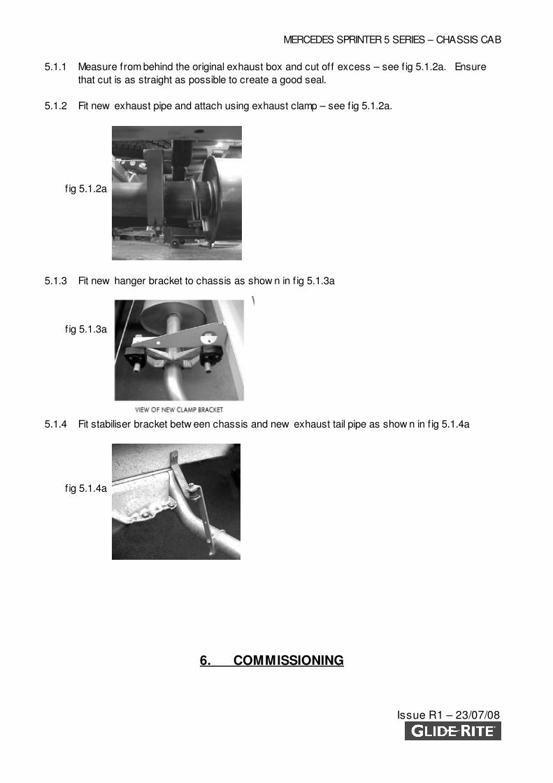
5.1.1 Measure from behind the original exhaust box and cut off excess – see f ig 5.1.2a. Ensure
that cut is as straight as possible to create a good seal.
5.1.2 Fit new exhaust pipe and attach using exhaust clamp – see f ig 5.1.2a.
5.1.3 Fit new hanger bracket to chassis as show n in f ig 5.1.3a
5.1.4 Fit stabiliser bracket betw een chassis and new exhaust tail pipe as show n in f ig 5.1.4a
6. COMMISSIONING
f ig 5.1.4a
f ig 5.1.3a
f ig 5.1.2a
MERCEDES SPRINTER 5 SERIES – CHASSIS CAB
Issue R1 – 23/07/08
6.1 CHARGING SEQUENCE
6.1.1 Using schrader valve, pressurise system to 120 psi (8 bar)
WARNING do not overcharge as this w ill result in component damage.
6.1.2 Turn on ignition.
6.1.3 Run compressor until it cuts out automatically.
6.1.4 Jack up rear axle. The ride height valve w ill now allow air into air bags and this w ill take the
w eight off axle stands.
6.1.5 Replace and torque road w heels to 200 Nm.
6.1.6 Remove axle stands and low er vehicle to ground.
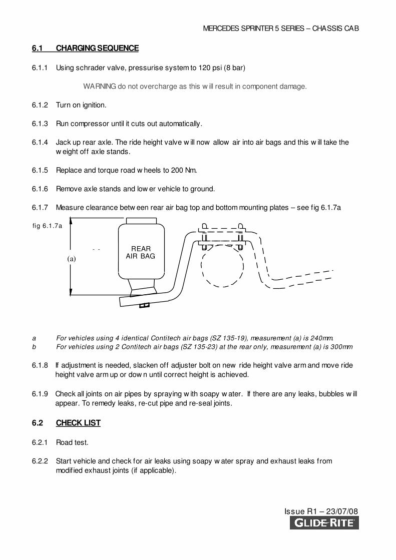
6.1.7 Measure clearance betw een rear air bag top and bottom mounting plates – see f ig 6.1.7a
a For vehicles using 4 identical Contitech air bags (SZ 135-19), measurement (a) is 240mm.
b For vehicles using 2 Contitech air bags (SZ 135-23) at the rear only, measurement (a) is 300mm
6.1.8 If adjustment is needed, slacken off adjuster bolt on new ride height valve arm and move ride
height valve arm up or dow n until correct height is achieved.
6.1.9 Check all joints on air pipes by spraying w ith soapy w ater. If there are any leaks, bubbles w ill
appear. To remedy leaks, re-cut pipe and re-seal joints.
6.2 CHECK LIST
6.2.1 Road test.
6.2.2 Start vehicle and check for air leaks using soapy w ater spray and exhaust leaks from
modif ied exhaust joints (if applicable).
REARAIR BAG
+0.0
-10.0300mm
fig 6.1.7a
(a)
MERCEDES SPRINTER 5 SERIES – CHASSIS CAB
Issue R1 – 23/07/08
6.2.3 Stickers – Operation stickers to be positioned on inside of rear and f ront door close to
operating sw itch (w here applicable).
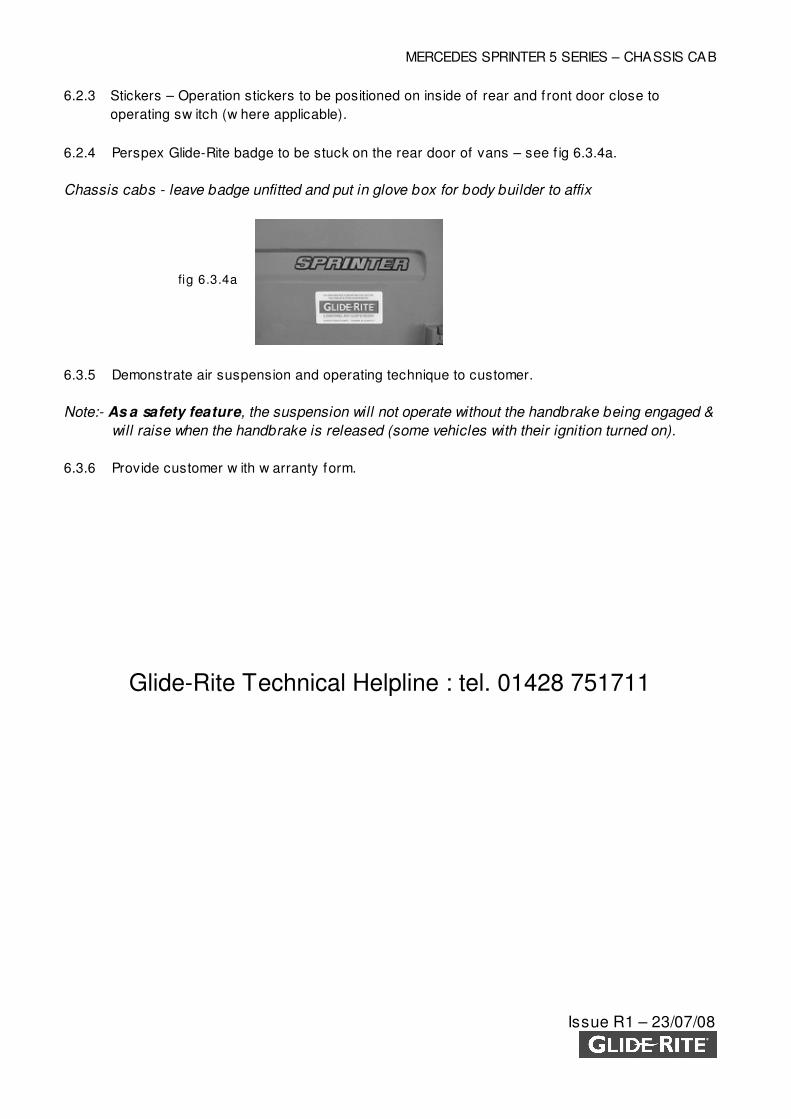
6.2.4 Perspex Glide-Rite badge to be stuck on the rear door of vans – see f ig 6.3.4a.
Chassis cabs - leave badge unfitted and put in glove box for body builder to affix
6.3.5 Demonstrate air suspension and operating technique to customer.
Note:- As a safety feature, the suspension will not operate without the handbrake being engaged &
will raise when the handbrake is released (some vehicles with their ignition turned on).
6.3.6 Provide customer w ith w arranty form.
Glide-Rite Technical Helpline : tel. 01428 751711
fig 6.3.4a
MERCEDES SPRINTER 5 SERIES – CHASSIS CAB
Issue R1 – 23/07/08
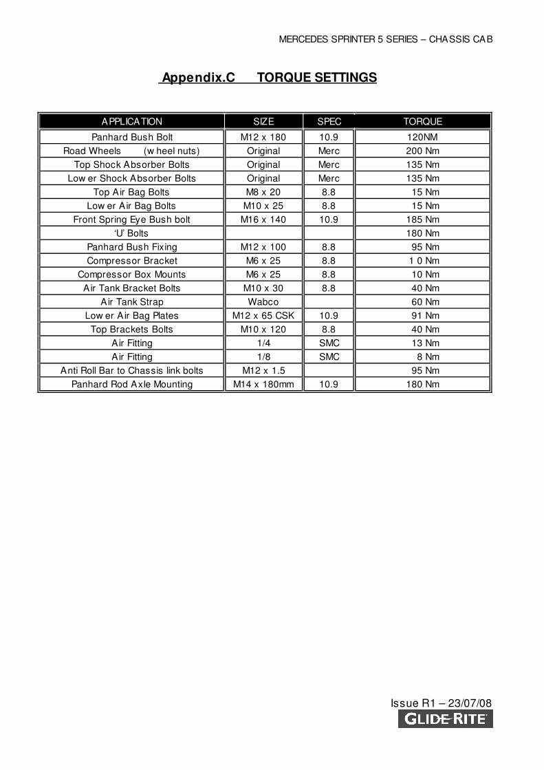
Appendix.C TORQUE SETTINGS
APPLICATION SIZE SPEC TORQUE
Panhard Bush Bolt M12 x 180 10.9 120NM
Road Wheels (w heel nuts) Original Merc 200 Nm
Top Shock Absorber Bolts Original Merc 135 Nm
Low er Shock Absorber Bolts Original Merc 135 Nm
Top Air Bag Bolts M8 x 20 8.8 15 Nm
Low er Air Bag Bolts M10 x 25 8.8 15 Nm
Front Spring Eye Bush bolt M16 x 140 10.9 185 Nm
‘U’ Bolts 180 Nm
Panhard Bush Fixing M12 x 100 8.8 95 Nm
Compressor Bracket M6 x 25 8.8 1 0 Nm
Compressor Box Mounts M6 x 25 8.8 10 Nm
Air Tank Bracket Bolts M10 x 30 8.8 40 Nm
Air Tank Strap Wabco 60 Nm
Low er Air Bag Plates M12 x 65 CSK 10.9 91 Nm
Top Brackets Bolts M10 x 120 8.8 40 Nm
Air Fitting 1/4 SMC 13 Nm
Air Fitting 1/8 SMC 8 Nm
Anti Roll Bar to Chassis link bolts M12 x 1.5 95 Nm
Panhard Rod Axle Mounting M14 x 180mm 10.9 180 Nm
MERCEDES SPRINTER 5 SERIES – CHASSIS CAB
Issue R1 – 23/07/08
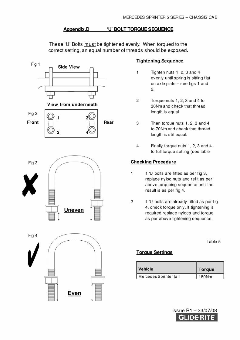
Appendix.D ‘U’ BOLT TORQUE SEQUENCE
These ‘U’ Bolts must be tightened evenly. When torqued to the
correct setting, an equal number of threads should be exposed.
Fig 1
Fig 2
Fig 3
Fig 4
Tightening Sequence
1 Tighten nuts 1, 2, 3 and 4
evenly until spring is sitting f lat
on axle plate – see f igs 1 and
2.
2 Torque nuts 1, 2, 3 and 4 to
30Nm and check that thread
length is equal.
3 Then torque nuts 1, 2, 3 and 4
to 70Nm and check that thread
length is still equal.
4 Finally torque nuts 1, 2, 3 and 4
to full torque setting (see table
1
2
3
4
Front
Rear
Checking Procedure
1 If ‘U’ bolts are f itted as per f ig 3,
replace nyloc nuts and ref it as per
above torqueing sequence until the
result is as per f ig 4.
2 If ‘U’ bolts are already f itted as per f ig
4, check torque only. If tightening is
required replace nylocs and torque
as per above tightening sequence.
Side View
View from underneath
Torque Settings
Vehicle Torque
Mercedes Sprinter (al l 180Nm
Rear
Table 5
MERCEDES SPRINTER 5 SERIES – CHASSIS CAB
Issue R1 – 23/07/08
Appendix E. ANTI-CORROSION TREATMENT AND PAINTWORK
The follow ing procedure should be follow ed in order to restore any broken surface to manufacturer’s
original specif ication.
1. Remove any f laky paintw ork and clean the surrounding area to leave no traces of grease,
dust or other contamination, using a heptane type solvent.
2. Apply tw o coats of a proprietary zinc-f ree primer.
3. Rub dow n the primed surfaces before applying a minimum of tw o top coats of original
matched colour or underseal.
4. All painted areas should be f inished w ith a good application of protective w ax seal.
5. In the event of any treatment to exterior paint surfaces, it is important to check the opposing
INTERIOR surface for any paintw ork damage and need for repair.