MENNEKES and EV - Elvira / FrontPage
41
MENNEKES and electric vehicle
Transcript of MENNEKES and EV - Elvira / FrontPage

MENNEKES and electric vehicle

Systemstructure
It looks so easy …
… but it is not.

Standard Charging 32A 400V AC
Fast Charging 200A 400V DC
Battery Exchange
Different Charging Conceptions
Systemstructure

Standard Charging 32A 400V AC
Fast Charging 200A 400V DC
Battery Exchange
Different Charging Conceptions
Systemstructure

Charging Station /Socket
Details of Standard Charging
Charging Cable Vehicle Interface
Systemstructure

Vehicle Coupler

Vehicle Coupler
Requirements from the IEC 62196-1
Current: 16A – 32A AC
Voltage: 230V single-phase
400V three-phase
Communication: necessary from vehicle to charge-
station
Plug in cycles: 10.000 times
Approvals: tested and approved regarding IEC 62196-1

Vehicle Coupler
MENNEKES CEEplus
The IEC 309-System is standardised all over the world
CEE plus is complete compatible to the IEC 309-System
CEEplus is tested and approved as vehicle coupler in regard to IEC 92196-1
The 16A power contacs are designed also for 32A and the system is available for 1 phase and for 3 phasecharging to reduce the charging time.
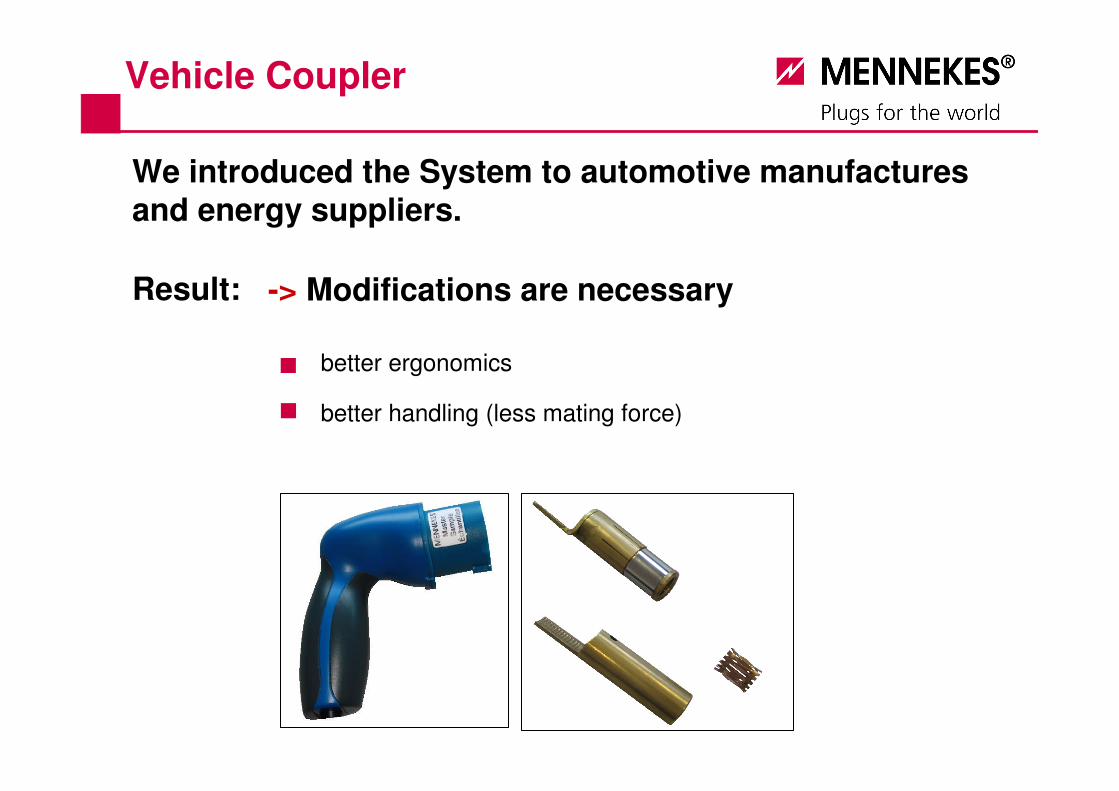
Vehicle Coupler
We introduced the System to automotive manufacturesand energy suppliers.
Result: -> Modifications are necessary
better ergonomics
better handling (less mating force)

Vehicle Coupler
e-mobility Berlin / MINI-E-Berlin
both projects will use the CEEplus system …
… but for the future there are
aditional requiremensts!

General System Specifications

General System Specifications
Communication
- Communication between Vehicle and Charging Station:
• Identification of Vehiclecode (e.g. for assignment of the Vehicle to the account of the ownerat the Power Supplier
- Communication between Vehicle and Power Supplier:
• Billing of delivered power
• Activation of Immobilizer System
• Identification of the Charging System of the Vehicle (what kind of Charging is needed?)
• Identification of accurate connection between Vehicle and Charging Station
• Accomplishment of RCD Control
• Clearance and termination of Charging Process
• Signal for interlocking of Charging System
• In the future: Controlled use of Vehicle Battery as power reservoir
• Controlled supply of power
• Provision of different rates
Between Vehicle and Charging Station communication is necessary. The current standards require additional contact in the plug and socket system, whereas the current developments prefer communication through Powerline.

Interlocking
- Electrical Interlocking
You cannot compare the Electric Charging with the fueling of a vehicle with a combustion engine. The user will especially notice that the charging process takes much more time than fueling.This means that – unlike when fueling – people will leave the car and so an unattended processtakes place. To avoid maloperation and unrequested stops of the charging process, defined interlocking processes are necessary.
The socket of the Charging Station always has to be de-energized, as long as there is no sufficient contact between Plug and Socket. We call this an Electrical Interlocking. This is done by a Contactor, which is checking if there is a sufficient contact between Plug and Socket.
This function ensures on the one hand, that there is no danger of electric shock at the Socket. On the other hand it makes sure, that there will be no plugging or unplugging under load.
General System Specifications

- Electro-Mechanical locking
To avoid that the Charging Process is stopped unrequested, e.g. to steal the Charging Cable or maliciously stopping the Charging Process it is necessary that the Plug and Socket of the Charging Cable are mechanically locked in the Charging Station and in the Vehicle.This Electro-Mechanical Interlocking is released with an electric signal, which is sent as soon as the Charging Process is started.The Charging Process can be started either automatically by communication between Vehicle and Charging Station, or by operating an input-terminal and the authorization by card system at the Charging Station (like a Customer Activated Terminal for fueling).
When the Charging Process is stopped and the Charging Cable is de-energized, the Electro-Mechanical Interlocking will be released.
To react on system malfunctions, which lead to an unwanted interlocking, an emergency release which is located inside the vehicle is necessary.
General System Specifications

Handling
Characteristics for Handling:
• The enclosures of the Plug and Sockets have to be ergonomically designed (slip-proof, no sharp edges, handy, …)
Charging an Electrical Car should be possible for any person without any problems.This demands, that the systems have to be self-explanatory and handy. For the Standard Charging a Charging Cable is carried in the Vehicle. Therefore it is necessary the the user operates a Plug-and-Socket-System both at the Vehicle and at the Charging Station. This operation should be as simple and handy as possible.
• Necessary interlocking and sealing processes have to be done automatically without additional operations.
• A clear orientation of the Plug to the Socket is essential
• The Sockets in the Vehicle and in the Charging Stations should be in an ideal position to ensure an optimal power flow when operating.
• Operating of protection caps and lids should be possible also with delicate hands (eventually with long finger nails). Eventually there will be no need of lids at all.
• The insert- and drawing forces are not allowed to excess a certain force also in a used condition.
General System Specifications

General System Specifications
Charging the batteries stops automatically if the batteries are full or in case of an external stopsignal.The complete charging process is finished if the locking of the plug is released and the plug is pulled out of the car and out of the charging station.The complete charging process and the locking of the plug has to be interuppted by an externalsignal. To secure that it is not possible to interuppt the charging process arbitary, two solutions areavailable:- To interrupt the charging process it is necessary to push a button at the inside of the car. So only
the car driver can do this.- To interrupt the charging process it is necessary to push a button which is located in the area of
the vehicle interface. It is possible to reach this buttom from outside, but it works only if the central-car-interlock is released.
Stop charging
If the plug is connected to the car and to the charging station the communication starts. After the control of the earth contact and the definition of the type of charging system is done, the chargingprocess starts automatically.
Start charging

Specification Charging Cable

Design:
The known IEC Standards cannot be used any longer!
Usually cables, e.g. extension cables have a Plug on the end and a Connector on the other hand. In the area of IEC standard Plugs and Sockets only the Connectors are considered as live parts; therefore only the contacts of the connector have to be protected against contact.
Assuming that in the future also a power extraction from the Vehicle batteries into the network or for external consumers can be done, the non-protected contacts of the Plug are a danger to life and health, as a current flow from the Connector to the Plug will energize the pins of the Plug.
If a power extraction from the Vehicle batteries is intended, Plug and Socket Systems which provides both isolated contacts in the Plug and in the Socket.
Specification Charging Cables

Specification Charging Cables

Special Charging Set: Plug and Socket
Specification Charging Cables

• Both ends of the Charging Cable are identical � simple and clear handling
Assuming that also the Plug is protected against contact, the Charging Cable can be equipped with a Plug on both sides and no Connector is needed. I.e. both in the vehicle and in the Charging Station nearly identical Sockets can be used.
• No flap lid on Charging Cable � simple handling / very robust
• Nearly identical sockets both in the vehicle and the Charging Station � simplified system, no appliance inlet necessary
Specification Charging Cables

The System is rated for 63A. To solve the problems with big cables it is necessary to use cables with different cross sections.
Here we think that the on-board Charging Cables for 32A are equipped with 6 mm² cables, whereas Charging Stations for public areas are equipped with fixed cables for 63A with 16 mm².
Therefore it is necessary to identify the cables before charging to avoid the use of a 6 mm² cable for 63A power. The identification can be done by different Resistant-Bridges between two signal contacts.
Encoding
- Amperage Encoding
Specification Charging Cables

Specification Charging Cables
Charging Cables will be assembled in that way, that they cannot be re-connected again, so that no opening and manipulating can be done.
Safety
To fulfill the communication demands, two signal contact and a Hybrid-Cable with an additional 1 x 0,5 mm² conductor are needed. If Powerline is used, the signal contacts are stil required but it is not necessary to use a special Hybrid-Cable any longer.It is also possible to use the “PLC-Charging-Systems“, designed by EDF.
Communication

Specification Charging Station

Design
There are different application areas, which do have different demands for Charging Stations. These miscellaneous demands are generally defined by the following conditions:
- Application inside or outside- Application in private or public area- Standard Charging or Fast Charging- Only power supply or power supply and billing- Authorization through Vehiclecode, with Card, with RFID (Radio Frequency Identification), or without any identification.
According to the definition of the Charging Cable one or more sockets will be built in the Charging Station.
Specification Charging Station
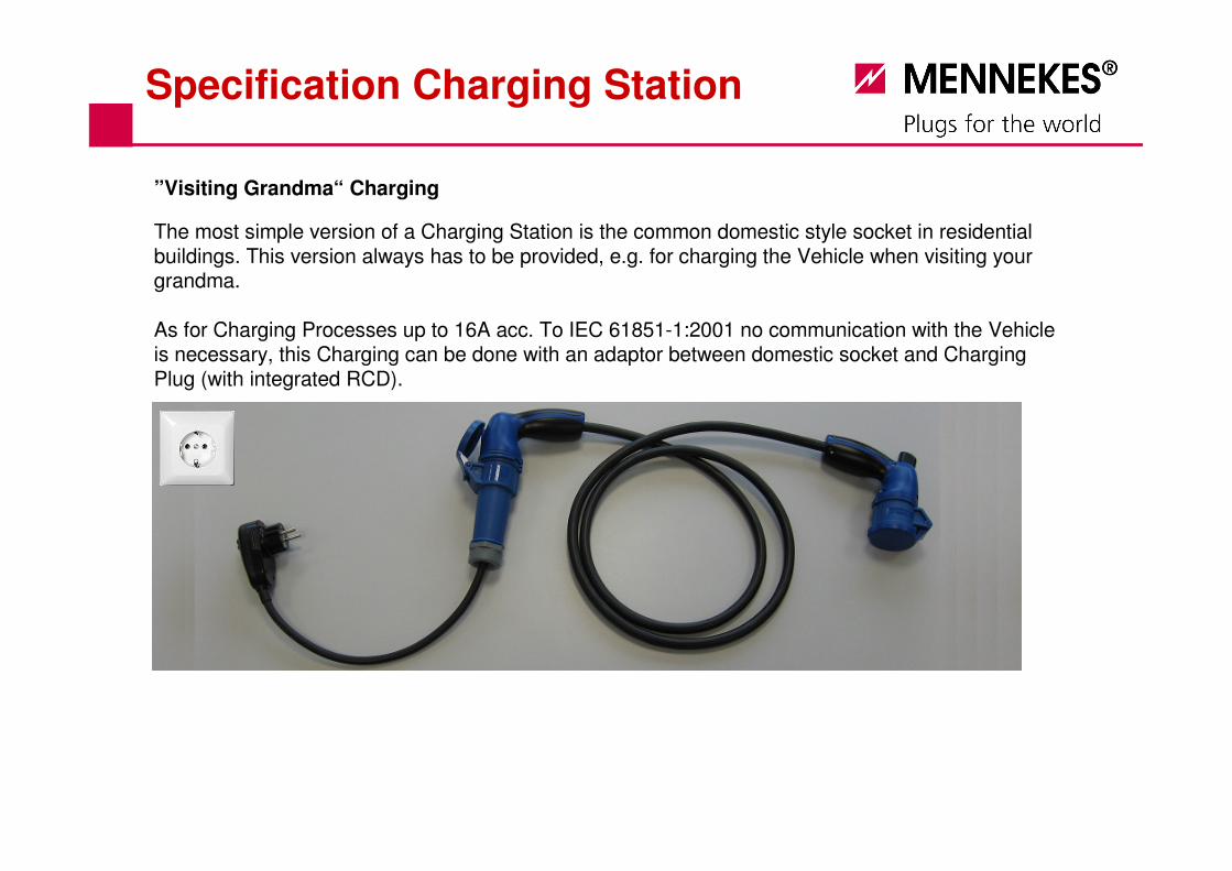
The most simple version of a Charging Station is the common domestic style socket in residential buildings. This version always has to be provided, e.g. for charging the Vehicle when visiting your grandma.
As for Charging Processes up to 16A acc. To IEC 61851-1:2001 no communication with the Vehicle is necessary, this Charging can be done with an adaptor between domestic socket and Charging Plug (with integrated RCD).
”Visiting Grandma“ Charging
Specification Charging Station

To reduce the Charging Time also at home to an acceptable limit, it makes sense to offer 32A Charging Station for residential buildings.
Standard Charging
For this, a communication between Charging Station and Vehicle is mandatory.The most simple version of communication can be done through a so called Wallbox, which communicates through different rectangular signals with the Vehicle; to query the relevant technical frame conditions and to accordingly adjust the Charging Station.
Specification Charging Station
If the communication shall be used for more than only adjusting the Charging Station, e.g. to do billings, a wallbox is not enough. For these application a processor or an Industrial PC if applicable should be used.
The communication itself can be done over additional Signal Contacts or by Powerline. If Powerline is used, a coupler in the Charging Station and in the Charging Electronic is necessary(A decision about such technology has to be done within the framework of the standardization process).
For a 32A Charging Station in public areas the same demands as in private areas are given, furthermore, the following points have to considered especially:
Standard Charging in public areas
It is preferable that the self-explanatory operation of MCB and RCD can be done by every user without hazards.
Standard solutions as well as optically enhanced units should be provided.
The sockets of the Charging Stations have to fulfill all requested demands for the interlocking systems (see General Specifications).
The Charging Stations have to be robust.
The billing of the Charging Service is mandatory, therefore a Vehicle identification or an authorization by card is necessary.
Specification Charging Station

Specification Charging Station
Standard Charging in public areas - Example

Basic Principle of the design of a Charging Station
Powerline Couple (alternatively to additional signal contacts)
RCD with external push button
MCB with external push button
Industrial PC (alternatively to Wallbox)
Wallbox (alternatively to Industrial PC)
Distribution Terminal BlockContactor
„Smartmeter“ Meter Reader
Socket; electrically an electro-mechanically interlocked
Specification Charging Station

The MENNEKES Development
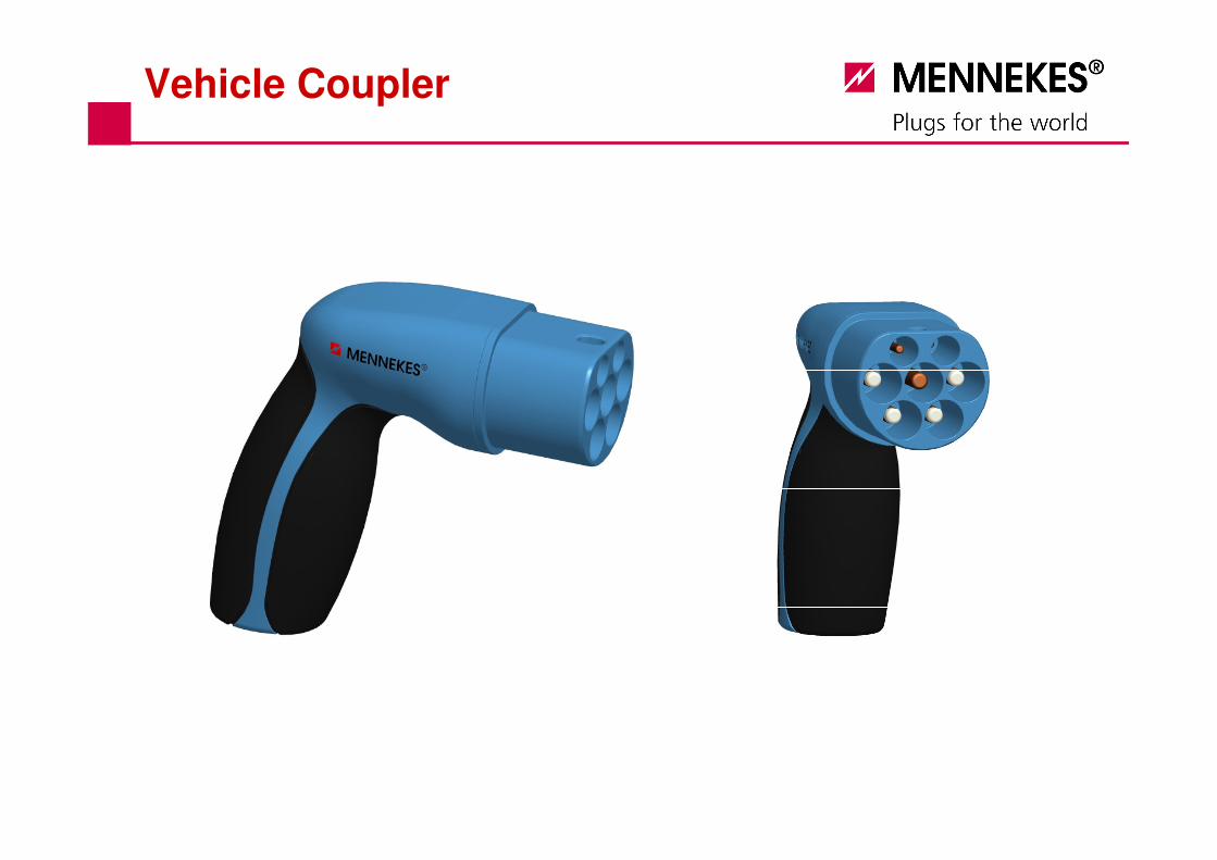
Vehicle Coupler

Vehicle Coupler

Vehicle Coupler

Vehicle Coupler

Vehicle Coupler

Charging Station
Bittte Karte anlegen
Bitte Karteanlegen
1
2
3
4

Charging Station
Bittte Karte anlegen
Bitte Karteanlegen
1
2
5
6
3
4 8
7

Charging Station Cable Electric Vehicle
Current:
Power Contact:
Signal Contact:
Interlock:
IP Grade:
Cover:
Dimension:
max. 63A
3p + N + PE
2p
elektromechanic
IP 44
lid
55 mm
max. 63A
3p + N + PE
2p
elektromechanic
IP 65
Screwed cover
55 mm
max. 63A
3p + N + PE
2p
-
IP 44
-
55 mm
Component
Spezification
System-Area
Infrastructure Socket Vehicle SocketThe same plug on both sides
MENNEKES Solution

Bittte Karte anlegen
Bitte Karteanlegen
1
2
5
6
3
4 8
7
MENNEKES Charging Systems

plugs for the world